EP1187136A2 - Laufwerk für flexible Platte - Google Patents
Laufwerk für flexible Platte Download PDFInfo
- Publication number
- EP1187136A2 EP1187136A2 EP01121215A EP01121215A EP1187136A2 EP 1187136 A2 EP1187136 A2 EP 1187136A2 EP 01121215 A EP01121215 A EP 01121215A EP 01121215 A EP01121215 A EP 01121215A EP 1187136 A2 EP1187136 A2 EP 1187136A2
- Authority
- EP
- European Patent Office
- Prior art keywords
- light emitting
- conductor
- emitting diode
- floppy disc
- driving device
- Prior art date
- Legal status (The legal status is an assumption and is not a legal conclusion. Google has not performed a legal analysis and makes no representation as to the accuracy of the status listed.)
- Withdrawn
Links
Images

Classifications
-
- G—PHYSICS
- G11—INFORMATION STORAGE
- G11B—INFORMATION STORAGE BASED ON RELATIVE MOVEMENT BETWEEN RECORD CARRIER AND TRANSDUCER
- G11B33/00—Constructional parts, details or accessories not provided for in the other groups of this subclass
- G11B33/12—Disposition of constructional parts in the apparatus, e.g. of power supply, of modules
- G11B33/121—Disposition of constructional parts in the apparatus, e.g. of power supply, of modules the apparatus comprising a single recording/reproducing device
- G11B33/122—Arrangements for providing electrical connections, e.g. connectors, cables, switches
-
- G—PHYSICS
- G11—INFORMATION STORAGE
- G11B—INFORMATION STORAGE BASED ON RELATIVE MOVEMENT BETWEEN RECORD CARRIER AND TRANSDUCER
- G11B33/00—Constructional parts, details or accessories not provided for in the other groups of this subclass
- G11B33/10—Indicating arrangements; Warning arrangements
Definitions
- This invention relates to a floppy disc driving device (FDD), and more particularly relates to a floppy disc driving device (FDD) located near a diskette insertion drawer having a light emitting diode (LED) driving circuit for emitting light when a floppy disc is being rotatively driven to ensure driving of the light emitting diode and to save the driving circuit cost.
- FDD floppy disc driving device
- LED light emitting diode
- a light emitting diode is located near a diskette insertion slot of a floppy disc driving device to light the light emitting diode when the floppy disc is rotatively driven for showing that the floppy disc is now being rotatively driven.
- a diskette insertion slot and a light emitting diode are located on the front side of the floppy disc driving device whereas an interface connector to be connected to an external main control unit (computer) is located on the back side of the floppy disc driving device.
- An integrated circuit (IC) for controllably driving the floppy disc driving device is also located on the back side of the floppy disc driving device.
- FIG. 3 is a circuit diagram for showing a typical equivalent circuit of a light emitting diode driving circuit that has been used for a conventional floppy disc driving device.
- the light emitting diode driving circuit is provided with a light emitting diode 31, a flexible printed circuit (FPC) 32 that is a component of a connection conductor, a current limiting resistor 33, and a voltage driving power source 34 contained in the integrated circuit (not shown in the figure).
- FPC flexible printed circuit
- the flexible printed circuit 32 is provided with a flexible copper (Cu) first conductor 32 1 and a flexible copper (Cu) second conductor 32 2 that are located in parallel with insulation between them, and the flexible printed circuit 32 is flat and band-shaped as the whole.
- the anode side of the light emitting diode 31 is connected to one end of the first conductor 32 1 of the flexible printed circuit 32, and on the other hand the cathode side is connected to one end of the second conductor 32 2 of the flexible printed circuit 32.
- One end of the current limiting resistor 33 is connected to the other end of the first conductor 32 1 of the flexible printed circuit 32, and on the other hand the other end of the current limiting resistor 33 is connected to the positive side terminal of the voltage driving power source 34.
- the negative side terminal of the voltage driving power source 34 is connected to the other end of the second conductor 32 2 of the flexible printed circuit 32.
- the voltage driving power source 34 When a diskette is inserted into the floppy disc driving device through the diskette insertion slot having the abovementioned configuration and a floppy disc in the inserted diskette is rotatively driven, the voltage driving power source 34 generates a driving voltage.
- the driving voltage causes a current flowing from the positive side terminal of the voltage driving power source 34 through the current limiting resistor 33, the first conductor 32 1 of the flexible printed circuit 32, the anode of the light emitting diode 31, the cathode of the light emitting diode 31, and the second conductor 32 2 of the flexible printed circuit 32 to the negative side terminal of the voltage driving power source 34, and the current activates the light emitting diode 31 and the light emitting diode 31 is lighted.
- the intensity of the current that flows through the light emitting diode 31 is kept approximately at a constant value due to interposition of the current limiting resistor 33, and the light emitting diode 31 is lighted approximately at a constant brightness due to substantial current driving.
- the abovementioned conventional floppy disc driving device is provided with the flexible printed circuit 32 for the light emitting diode driving circuit, and the flexible printed circuit 32 uses a conducting wire formed of copper (Cu) and the conductive wire is long.
- Cu copper
- a method in which a membrane conductor, which is generally more inexpensive than the flexible printed circuit 32, is used may be employed.
- a membrane conductor cannot be used instead of a flexible printed circuit 32 without any additional contrivance because the resistance value of the membrane conductor is considerably higher than that of the flexible printed circuit 32 and the resistance value of a membrane conductor changes significantly with temperature change and humidity change. It is difficult to maintain light emitting brightness of a light emitting diode at a constant value continuously, and the light emitting brightness of a light emitting diode cannot be stabilized.
- the present invention has been accomplished in view of the abovementioned technical background, and it is an object of the present invention to provide a low-cost floppy disc driving device that maintains light emitting brightness of a light emitting diode at a constant value continuously in which a membrane conductor is used for connecting between a light emitting diode and an integrated circuit for current driving of the light emitting diode.
- a floppy disc driving device in accordance with the present invention is provided with a circuit substrate formed on one side of a chassis on which at least an integrated circuit and an interface connector are mounted, a light emitting diode located near the diskette insertion slot that emits light when a floppy disc is rotatively driven, and a connection conductor that connects between the circuit substrate and the light emitting diode, wherein the connection conductor is a membrane conductor formed by spreading coating material on one side of the chassis, and the light emitting diode is driven with a current supplied from the integrated circuit through the membrane conductor.
- the membrane connector is considerably more inexpensive than that of a flexible printed circuit, which has been used as the conventional connection conductor of this type, and furthermore because the light emitting diode is driven with a current supplied from the integrated circuit through the membrane conductor, a current that flows through the light emitting diode can be maintained approximately at a constant value to resultantly maintain light emitting brightness of the light emitting diode at a constant value continuously even though a relatively high resistance value of the membrane conductor is changed or a resistance value varies significantly due to an environmental temperature change or an environmental humidity change
- the membrane conductor in the abovementioned means preferably contains carbon powder or silver paste as a main component.
- the membrane conductor By forming the membrane conductor as described hereinabove, the membrane conductor can be obtained by means of relatively simple means, and the membrane conductor is manufactured at a low cost.
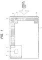
- FIG. 1 is a front view showing one side of a chassis of an exemplary embodiment of a floppy disc driving device in accordance with the present invention.
- the floppy disc driving device in accordance with the present embodiment is provided with a chassis 1, a circuit substrate 2 mounted on one side of the chassis 1, an integrated circuit (IC) 3 and an interface connector 4 which are mounted on the circuit substrate 2, a front panel 5 having a diskette insertion slot (not shown in the drawing), a light emitting diode (LED) 6 located opposingly to a small aperture (not shown in the drawing) formed near the diskette insertion slot of the front panel 5, a membrane (coating film) conductor 7 that has been formed by spreading coating film material consisting mainly of carbon (C) particles on one side of the chassis 1, and a switch 8 provided in the chassis 1 that is served to switch the operation when a diskette is inserted or drawn out.
- a chassis 1 a circuit substrate 2 mounted on one side of the chassis 1, an integrated circuit (IC) 3 and an interface connector 4 which are mounted on the circuit substrate 2, a front panel 5 having a diskette insertion slot (not shown in the drawing), a light emitting diode (LED) 6 located oppos
- the circuit substrate 2 is mounted on one side of the chassis 1 located near the back side of the floppy disc driving device.
- the integrated circuit 3 that is mounted on the circuit substrate 2 is located approximately at the center of the circuit substrate 2, and is provided with a built-in control unit (not shown in FIG. 1) that is served to control components of the floppy disc driving device and a built-in current driving power source (not shown in FIG. 1) that is served for current driving of the light emitting diode 6.
- the interface connector 4 that is also mounted on the circuit substrate 2 is located on the back side of the floppy disc driving device, and is served to connect the control unit in the integrated circuit 3 to an external control unit such as a computer.
- the light emitting diode 6 is connected to the current driving power source in the integrated circuit 3 through the membrane conductor 7.
- the membrane conductor 7 is formed along the one side edge of the chassis 1 from the back side to the front side on the one side of the chassis 1 extending from the connector (not shown in the drawing) formed on the circuit substrate 2 to the light emitting diode 6, and a part of the membrane conductor 7 extends to the position where the switch 8 is located.
- FIG. 2 is a circuit diagram showing an equivalent circuit of the light emitting diode driving circuit in the floppy disc driving device shown in FIG. 1.
- the same components shown in FIG. 2 as shown in FIG. 1 are given the same numerals.
- the light emitting diode driving circuit constitutes the light emitting diode (LED) 6 and the connection conductor, and is provided with a membrane conductor 7 having a first conductor 7 1 and the second conductor 7 2 and a current driving power source 9 that is provided in the integrated circuit 3.
- the anode of the light emitting diode 6 is connected to one end of the first conductor 7 1 of the membrane conductor 7, and the cathode is connected to one end of the second conductor 7 2 of the membrane conductor 7.
- the other end of the first conductor 7 1 of the membrane conductor 7 is connected to one end of the current driving power source 9, and the other end of the second conductor 7 2 is connected to the other end of the current driving power source 9.
- the operation of the light emitting diode driving circuit having the abovementioned configuration will be described hereunder.
- the current driving power source 9 in the integrated circuit 3 is driven synchronously with rotation driving of the floppy disc, and a driving current is generated from the current driving power source 9.
- the output driving current is supplied from the one end of the current driving power source 9 to the anode of the light emitting diode 6 through the first conductor 7 1 of the membrane conductor 7, and then supplied from the cathode of the light emitting diode 6 to the other end of the current driving power source 9 through the second conductor 7 2 of the membrane conductor 7. As the result the driving current is supplied to light the light emitting diode 6.
- the resistance value of the first conductor 7 1 and the second conductor 7 2 of the membrane conductor 7 is relatively higher than a resistance value of a first conductor and a second conductor of a known flexible printed circuit and the resistance value of the first conductor 7 1 and the second conductor 7 2 of the membrane conductor 7 changes relatively more significantly due to environmental temperature change and humidity change than the resistance value of the first conductor and the second conductor of the conventional flexible printed circuit.
- the membrane conductor 7 is formed by spreading coating material containing carbon (C) particles as a main component is exemplary described in the abovementioned embodiment, however, the coating material used for forming the membrane conductor 7 of the floppy disc driving device in accordance with the present invention is by no means limited to coating material containing carbon (C) as the main component.
- coating material containing silver (Ag) paste as a main component may be used though coating material containing silver paste as a main component is more expensive than coating material containing carbon (C) as a main component.
- connection conductor of the membrane conductor 7 for connecting between the integrated circuit 3 and the light emitting diode 6 formed of coating material containing carbon (C) particles as a main component or the use of the membrane conductor 7 formed of coating material containing silver (Ag) paste as a main component allows the membrane conductor 7 to be formed easily by applying well-known simple coating film forming technique, and the manufacturing cost of the connection conductor is lower than that of the known connection conductor that is provided with the flexible printed circuit as the connection conductor for connecting between the integrated circuit 3 and the light emitting diode 6.
- the membrane conductor formed by spreading coating material on one side of the chassis as the connection conductor for connecting between the circuit substrate and the light emitting diode is significantly more inexpensive than the known flexible printed circuit that has been used as the connection conductor of this type. Furthermore, a current that flows through the light emitting diode can be maintained at a constant value even though the resistance value of the membrane conductor changes significantly with changing of environmental temperature and environmental humidity and the resistance value of the membrane conductor is relatively high because the light emitting diode is driven with a current through membrane conductor from the integrated circuit. As the result, light emitting brightness of the light emitting diode can be maintained at a constant value continuously.
Landscapes
- Led Device Packages (AREA)
- Illuminated Signs And Luminous Advertising (AREA)
- Printers Or Recording Devices Using Electromagnetic And Radiation Means (AREA)
Applications Claiming Priority (2)
| Application Number | Priority Date | Filing Date | Title |
|---|---|---|---|
| JP2000269002A JP2002074930A (ja) | 2000-09-05 | 2000-09-05 | フロッピー(登録商標)ディスク駆動装置 |
| JP2000269002 | 2000-09-05 |
Publications (2)
| Publication Number | Publication Date |
|---|---|
| EP1187136A2 true EP1187136A2 (de) | 2002-03-13 |
| EP1187136A3 EP1187136A3 (de) | 2002-04-17 |
Family
ID=18755692
Family Applications (1)
| Application Number | Title | Priority Date | Filing Date |
|---|---|---|---|
| EP01121215A Withdrawn EP1187136A3 (de) | 2000-09-05 | 2001-09-05 | Laufwerk für flexible Platte |
Country Status (4)
| Country | Link |
|---|---|
| US (1) | US6775095B2 (de) |
| EP (1) | EP1187136A3 (de) |
| JP (1) | JP2002074930A (de) |
| CN (1) | CN1171232C (de) |
Families Citing this family (2)
| Publication number | Priority date | Publication date | Assignee | Title |
|---|---|---|---|---|
| TWI273873B (en) * | 2003-12-22 | 2007-02-11 | Quanta Comp Inc | HDD tray mechanism |
| DE112011105765T5 (de) * | 2011-10-25 | 2014-09-18 | Hewlett-Packard Development Company, L.P. | Laufwerkträgersubstrat |
Family Cites Families (15)
| Publication number | Priority date | Publication date | Assignee | Title |
|---|---|---|---|---|
| US4547820A (en) | 1983-01-07 | 1985-10-15 | Tokyo Electric Co., Ltd. | Floppy disk drive apparatus |
| JPS6061951A (ja) | 1983-09-14 | 1985-04-09 | Teac Co | デイスク駆動装置 |
| US4652950A (en) * | 1983-10-07 | 1987-03-24 | Tokyo Electric Co., Ltd. | Floppy disc driving apparatus |
| US4626942A (en) * | 1984-03-02 | 1986-12-02 | Teac Corporation | Power-saving data transfer apparatus with a flexible magnetic disk or the like |
| JPS6238576A (ja) | 1985-08-14 | 1987-02-19 | Fuji Photo Film Co Ltd | 磁気記録再生装置における回転磁気記録媒体の保護方法 |
| US4855849A (en) * | 1986-04-21 | 1989-08-08 | Iomega Corporation | Disk drive motor mount |
| US4809115A (en) | 1987-07-17 | 1989-02-28 | Hitachi, Ltd. | Magnetic recording and reproducing apparatus |
| JPS6442061A (en) | 1987-08-06 | 1989-02-14 | Kyushu Nippon Electric | Floppy disk unit |
| US4967291A (en) * | 1988-11-02 | 1990-10-30 | Miniscribe Corporation | Method and apparatus for preventing an over-velocity error condition of a hard disk drive system |
| JPH02183485A (ja) | 1989-01-06 | 1990-07-18 | Nec Corp | フロッピィディスクドライブ |
| JPH087930B2 (ja) | 1990-03-16 | 1996-01-29 | 松下電器産業株式会社 | フロッピーディスク装置 |
| US5278718A (en) | 1991-05-24 | 1994-01-11 | Samsung Electronics Co., Ltd. | Circuit for generating a disk change signal |
| JPH07262680A (ja) | 1994-03-17 | 1995-10-13 | Seiko Epson Corp | 記録または再生装置のディスク挿入検出機構 |
| JP2658954B2 (ja) | 1995-03-23 | 1997-09-30 | 日本電気株式会社 | 磁気ディスク装置用ディスクドライブユニット |
| US5754112A (en) | 1995-09-28 | 1998-05-19 | Sun Microsystems, Inc. | Power on, mated, and activity indicator for electronic devices including storage devices |
-
2000
- 2000-09-05 JP JP2000269002A patent/JP2002074930A/ja not_active Withdrawn
-
2001
- 2001-08-28 CN CNB011309490A patent/CN1171232C/zh not_active Expired - Fee Related
- 2001-08-30 US US09/944,621 patent/US6775095B2/en not_active Expired - Fee Related
- 2001-09-05 EP EP01121215A patent/EP1187136A3/de not_active Withdrawn
Also Published As
| Publication number | Publication date |
|---|---|
| CN1171232C (zh) | 2004-10-13 |
| CN1341940A (zh) | 2002-03-27 |
| EP1187136A3 (de) | 2002-04-17 |
| US6775095B2 (en) | 2004-08-10 |
| US20020027743A1 (en) | 2002-03-07 |
| JP2002074930A (ja) | 2002-03-15 |
Similar Documents
| Publication | Publication Date | Title |
|---|---|---|
| US7261437B2 (en) | Wedge-based lamp with LED light engine and method of making the lamp | |
| EP1727207A3 (de) | Flache Bildanzeigevorrichtung | |
| US7186015B2 (en) | Backlight display system | |
| EP1279344A3 (de) | Licht-, audio - und strombetriebene Einrichtungen, Befestigungen und Vorrichtungen mit stromleitenden Zusammensetzungen | |
| AU2005226630A1 (en) | Parallel/series LED strip | |
| CA2418591A1 (en) | Electrical air heating apparatus in particular for a motor vehicle | |
| US7071618B2 (en) | Electroluminescent element comprising electrically coupled shield layer | |
| US6775095B2 (en) | Floppy disc driving device | |
| EP2634474A1 (de) | Lichtemittierendes modul | |
| US5839810A (en) | Display gauge | |
| JPH11133394A (ja) | 液晶表示装置 | |
| JPH06230728A (ja) | フラットディスプレイ装置の接続構造 | |
| KR200487473Y1 (ko) | 전자 낚시찌 | |
| TWI736316B (zh) | 光源模組以及具有光源模組的電子裝置 | |
| CN1144259C (zh) | 电致发光灯和用于这种灯的无纤焊弹夹电接头 | |
| CN102027285A (zh) | 采用导线束合方法的引线框及使用该引线框的led电源灯 | |
| KR100346549B1 (ko) | 형광표시관 모듈 | |
| CN216813812U (zh) | 一种适用于开关或指示灯的led组件 | |
| CN212229611U (zh) | 一种绑定结构、触摸屏、显示屏与触摸显示屏 | |
| CN211118804U (zh) | 条形灯软板及条形灯 | |
| JP3314725B2 (ja) | ステッピングモータの接続構造 | |
| JP2002198618A (ja) | 配線基板及び遊技機 | |
| CN2926810Y (zh) | 一种led光源模块 | |
| JPH11297470A (ja) | 照光ユニット | |
| JPH0644075Y2 (ja) | エレクトロルミネセンスのコネクタ取付構造 |
Legal Events
| Date | Code | Title | Description |
|---|---|---|---|
| PUAI | Public reference made under article 153(3) epc to a published international application that has entered the european phase |
Free format text: ORIGINAL CODE: 0009012 |
|
| PUAL | Search report despatched |
Free format text: ORIGINAL CODE: 0009013 |
|
| AK | Designated contracting states |
Kind code of ref document: A2 Designated state(s): AT BE CH CY DE DK ES FI FR GB GR IE IT LI LU MC NL PT SE TR Kind code of ref document: A2 Designated state(s): DE FR GB |
|
| AX | Request for extension of the european patent |
Free format text: AL;LT;LV;MK;RO;SI |
|
| AK | Designated contracting states |
Kind code of ref document: A3 Designated state(s): AT BE CH CY DE DK ES FI FR GB GR IE IT LI LU MC NL PT SE TR |
|
| AX | Request for extension of the european patent |
Free format text: AL;LT;LV;MK;RO;SI |
|
| 17P | Request for examination filed |
Effective date: 20020701 |
|
| AKX | Designation fees paid |
Free format text: DE FR GB |
|
| 17Q | First examination report despatched |
Effective date: 20040624 |
|
| GRAP | Despatch of communication of intention to grant a patent |
Free format text: ORIGINAL CODE: EPIDOSNIGR1 |
|
| STAA | Information on the status of an ep patent application or granted ep patent |
Free format text: STATUS: THE APPLICATION IS DEEMED TO BE WITHDRAWN |
|
| 18D | Application deemed to be withdrawn |
Effective date: 20050922 |