EP1187084A2 - Informationsflächenträger - Google Patents
Informationsflächenträger Download PDFInfo
- Publication number
- EP1187084A2 EP1187084A2 EP01121267A EP01121267A EP1187084A2 EP 1187084 A2 EP1187084 A2 EP 1187084A2 EP 01121267 A EP01121267 A EP 01121267A EP 01121267 A EP01121267 A EP 01121267A EP 1187084 A2 EP1187084 A2 EP 1187084A2
- Authority
- EP
- European Patent Office
- Prior art keywords
- information surface
- information
- carrier according
- surface carrier
- supporting part
- Prior art date
- Legal status (The legal status is an assumption and is not a legal conclusion. Google has not performed a legal analysis and makes no representation as to the accuracy of the status listed.)
- Withdrawn
Links
Images


Classifications
-
- G—PHYSICS
- G09—EDUCATION; CRYPTOGRAPHY; DISPLAY; ADVERTISING; SEALS
- G09F—DISPLAYING; ADVERTISING; SIGNS; LABELS OR NAME-PLATES; SEALS
- G09F21/00—Mobile visual advertising
-
- G—PHYSICS
- G09—EDUCATION; CRYPTOGRAPHY; DISPLAY; ADVERTISING; SEALS
- G09F—DISPLAYING; ADVERTISING; SIGNS; LABELS OR NAME-PLATES; SEALS
- G09F15/00—Boards, hoardings, pillars, or like structures for notices, placards, posters, or the like
Definitions
- the invention relates to an information surface carrier with at least one Information carrier area, especially for advertising material.
- an information carrier on at least one To offer information carrier area visually recognizable information. This requires at least the largest possible information carrier area, by as many as possible To be able to record information or information of a certain size. This is a relatively large one for an information surface carrier Desired construction, at least one information carrier surface more desirable To be able to arrange size on it. In addition, the Information desirable.
- advertising pillars is a cylindrical outer surface as Information carrier area available, on the messages in general and in particular Advertising materials are presented in written or graphic form.
- the curved information carrier surface has the advantage that an observer both when he is directly on the information carrier surface to move as well as if he moves about tangentially, at least one Part of the information carrier area is seen.
- the disadvantage is that the construction an information surface in the form of an advertising pillar in horizontal section is relatively large and is therefore particularly suitable for a mobile installation Buildings and not suitable for installation at different locations.
- the invention has for its object an information surface carrier present type so that, while ensuring a good view of the Information carrier surface of the information surface carrier also for proportional small locations, especially for indoor use.
- the information surface carrier according to claim 1 has two information carrier surfaces on, one of which is arched and the other is level. This makes a and the same information surface carrier is both for such a location at which the observers move past the arched information carrier surface as well for such a location to which a movement path for observers on the Information carrier surface is directed.
- Information surface carriers of relatively small width which is due to the circular cross-sectional shape in the horizontal section is specified. Which horizontal width extending between the broad sides of the information surface carrier is smaller than the radius of curvature of the curved information carrier surface. This width is preferably only one sixth to one fifth of that Radius of curvature.
- Another advantage of the configuration according to the invention is in that the information surface carrier with its flat broadside not only space-saving but also conveniently positioned on or near a wall can, giving a good positional image and taking up little space.
- the Information surface carrier according to the invention both for level and for appropriately curved auxiliary information surface carrier is suitable. It can be around thin-walled, e.g. sheet metal add-on parts that only consist of one vertical wall or be angular in the sense of subjects can, and the back is flat or can be curved accordingly, so that you either on one or the other broadside with a good field of vision on Information surface carriers can be kept.
- the bracket serves at least a vertical undercut groove, in the known mounting elements can be used, moved vertically and locked in the desired position.
- a groove arranged centrally with respect to the associated broadside leads to the advantage that that an auxiliary information surface carrier in the form of an attachment with a central bracket can be kept stable in its upper area.
- the information surface carrier in particular when the width-side width dimension of the information surface carrier is large in order to provide a correspondingly wide information carrier surface It is advantageous to have the information surface carrier out of two to form juxtaposed support members that face each other Narrow sides preferably by means of corresponding fastening elements are releasably attached to each other.
- the two-part design enables one Prefabricated manufacture of the associated supporting parts in a smaller design, whereby a simplified production is possible, especially if the Support parts through vertically extending profiles, especially made of light material, are formed, which in the case of thin-walled hollow profile design, the cost of materials and the weight can be kept low.
- the invention is further based on the object of an information surface carrier of the present type so that it is proportionate to at least one large information carrier surface can be formed with simple or can be manufactured by conventional means and easily transported or by Location can be moved to location. Such a shift is said to be carried out with as little effort as possible and manually.
- relatively small passages on the transport route can be predetermined, through which the information surface carrier can be moved have to be.
- the information surface carrier according to claim 7 consists of at least two supporting parts each in the form of a profile-shaped body with an elongated cross-sectional shape in horizontal section, the supporting parts preferably detachable on a dividing joint are built together, which are transverse to the broad side of the information surface carrier extends.
- This allows a relatively large information area realize, due to the composite design or divisibility can reduce the size of the information surface carrier and / or its weight and therefore the manufacture and / or transport or movement of the supporting parts of the Information surface carrier between two positions easier, with less Effort and particularly easy to handle.
- a simple manufacture is given in that the supporting parts in their Manufacturing process in acceptable sizes are easier to manufacture and handle can, where they complement each other in modular form when assembled.
- the Fastening elements are located on the information surface carrier according to the invention on related narrow sides of the supporting parts, being from the front or have a distance from opposite broad sides of the supporting parts and are thus offset inwards with respect to these sides. This makes them Fasteners removed from a view of the front or on the broad sides or at least in the background, so that it covers the information area and do not interfere with the information shown on it or such impairment Reduce.
- the mounting of additional auxiliary information surface carriers already described A vertical undercut is used in the form of attachments Groove.
- the Information surface supports made of two or more supporting parts in the form of hollow profiles and / or consists of light material.
- a light metal is suitable for this, e.g. Aluminum, or cardboard, from which the supporting parts e.g. by folding. It is therefore also advantageous, the at least two supporting parts of the information surface carrier to form from hollow-shaped bodies, resulting in a material saving lightweight and also stable construction leads.
- the information surface carrier can be of considerable size, one is easy and quick to assemble or disassemble important. This Demand can be achieved by various configurations of the fasteners realize.
- two belonging to each other Fastening elements which engage in a hook shape on one longitudinal edge of the Partition joint a joint around which the associated supporting parts in their side by side arranged fastening end position are pivotable.
- Two opposite, fastening elements belonging to one another form a preferably releasable Latching device that when pivoting the supporting parts in their end position lock automatically and thereby stabilize the setting of the supporting parts.
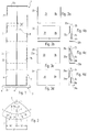
- the information surface stand designated in its entirety by 1 comprises the Embodiment according to FIGS. 1 and 2, which consist of two supporting parts 2a, 2b Information surface carrier 2 and a base 3, from which the information surface carrier 2 extends vertically upwards in the form of a column.
- the base 3 can be formed by a base plate 3a, which directly or by means of several flat Foot pieces 4 is on a floor, not shown, the foot pieces 4 in Edge area of the underside of the base plate 3a distributed over its circumference on the Base plate 3a are attached.
- the base plate 3a has an approximately triangular shape with preferably convex curved sides and rounded corners.
- the triangular basic shape of the base plate 3a is in the sense of an isosceles Triangular, i.e. which is preferably curved in a circular segment Front 5 of the base plate 3a is wider than the other two sides of the Triangle.
- the information surface carrier 2 having an elongated cross-sectional shape is arranged approximately parallel to the front side 5, with respect to the front side 5 in the central area of the triangular shape is offset and attached to the base plate 3a is, e.g. through the base plate 3a and into the information surface support 2 including fastening screws, not shown.
- the support parts 2a, 2b also have an elongated cross-sectional shape, whose larger cross-sectional dimension extends at right angles to the central plane E.
- the support parts 2a, 2b are releasably attached to one another at a dividing joint T which is located essentially in the middle plane E.
- the larger cross-sectional dimension the elongated cross-sectional shapes extend perpendicular to the vertical Middle plane E.
- the information surface carrier 2 thus has front and rear broad sides Bv, Br on, and narrow sides in a vertical arrangement on.
- the information surface carrier 2 has no narrow sides. If you have the Rounding the corners 7 considered as narrow sides, these are relatively narrow educated.
- the support parts 2a, 2b each have on their mutually facing sides Narrow sides S1, S2, which abut one another approximately in the central plane E.
- the Broad sides of the support parts 2a, 2b are designated Bv1, Bv2, Br1, Br2.
- the information carrier 2 has at least one on its front side 5 Information carrier surface 8, which extends over part of the height or over the entire Height of the information surface carrier 2 can extend and in horizontal cross section is convex.
- Information carrier surface 8 is preferably one cylindrical section surface, the axis of curvature, not shown, vertical runs.
- the rear side 6 of the information surface carrier 2 is preferably a flat one Area that is also at least part of its height and / or width Can form information carrier surface 8a.
- the support parts 2a, 2b are each supported by a support part body 2c Fasteners 11, 12, 13, 14 formed (Fig. 5).
- the supporting part body 2c have a mirror-symmetrical shape with respect to the central plane E. Your horizontal Cross-sectional shapes are with respect to one perpendicular to the median plane E.
- the supporting part body 2c itself for reasons of weight saving preferably have vertically extending cavities 15a, of three vertical walls are surrounded, namely a front wall 16 and a rear wall 17, the on the opposite broad sides Bv1, Bv2, Br1, Br2 the Support part body 2c are arranged, and one of the front wall 16 and the rear wall 17th interconnecting narrow-side transverse wall 18.
- the front wall 16 and the rear wall 17 form the cross-sectional shape of the transverse wall 18 opposite and preferably rounded corner 7.
- the support member bodies 2c are preferably in the form of vertically extending ones Profiles P formed, whose longitudinal central axes Pa extend vertically and to both Sides of the central plane E are arranged.
- the fasteners 11 to 14 can in the longitudinal direction of the profile, i.e. parallel to the profile axes Pa, only over part the profile length, here the height of the supporting part body 2c, e.g. above and below be arranged, or extend continuously so that they are in the longitudinal direction of the profile are continuous profile sections.
- the fasteners 11 to 14 can on the in the assembly position facing edges of the front wall 16 and Rear wall 17 and / or arranged on the transverse wall 18, in particular in one piece be formed or molded.
- the division joint T can be one in the true sense, in which contact surfaces of the supporting parts 2a, 2b extending in the central plane E lie against one another.
- the present exemplary embodiment is a theoretical one Partition joint T, which is characterized by a positive locking of the Fasteners to each other and runs in the central plane E.
- two arranged on the narrow sides S1, S2 and together are sufficient cooperating fasteners from the support parts 2a, 2b on the Partition joint T to connect with each other and against a displacement transverse to Secure information carrier surface 8 to each other.
- a pair of fasteners can it be e.g. act as a locking device.
- Tv1, Tv2 are on the front edges and at the rear edges Tr1, Tr2 of the dividing joint T two each Fastening elements 11, 12 and 13, 14 are provided, which have a relative movement between the support parts 2a, 2b transversely to the division joint T and transversely to Prevent information carrier surface 8.
- the front fasteners 13, 14 can be those which engage behind one another in the form of a hook, wherein they can be plugged together in a position of the support parts 2a, 2b in their rear grip position are and a joint 21 with the associated parting edge Tv2 or in it Form near extending hinge axis 21a about which the support parts 2a, 2b pivotable are.
- the rear fastening elements 11, 12 preferably form one Locking device 22 with a locking lug 22a on one Fastening element and one interacting with the locking lug Locking edge 22b on the other fastening element.
- the fastening elements 11, 12, 13, 14 one each projecting inwards from the associated broadside wall 16, 17 first leg 11a, 12a, 13a, 14a and an adjoining second Legs 11b, 12b, 13b, 14b, the latter extending towards one another, interact positively with each other and preferably both second Leg protrude beyond the division joint T or median plane E.
- That e.g. on face arranged hinge 21 is formed by a circular arc section around the vertical Axis of rotation 21a curved guide groove 14c in the leg 14b and one correspondingly curved guide web 13c formed on the legs 13a and 13b.
- the Guide web 13c is in the guide groove 14c with little play slidable in an arc.
- the length of the guide arc section is so long dimensioned, and its bisector Wh is arranged so that on the one hand Arc engagement in the final assembly position of the support parts 2a, 2b against them in a form-fitting manner one directed transversely to the central plane E and transversely to the front or rear 5, 6 Movement blocks, and on the other hand in an assembly start position in which the other Fastening element pair 11, 12 is separated from each other, the guide web 13c in the Guide groove 14c is insertable.
- the cuts Bisecting angle Wh the central plane E in the region of the second legs 13b, 14b, where the bisector Wh the median plane E at an angle W of preferably cuts about 30 to 45 °, which is open to the inside.
- the pair of fasteners 11, 12 is preferably also with legs 11a, 12a, 11b, 12b in the above-described sense of the legs 13a, 13b, 14a, 14b, wherein the legs 11b, 12b overlap each other in the final assembly position and lock together by means of the locking lug 22a and locking edge 22b, which on the mutually facing sides of the legs 11b, 12b are arranged.
- the Locking takes place automatically when swiveling in, one leg, e.g. the Rebound legs 12b, or both legs 11b, 12b and through their own elasticity compress again.
- the locking device 22 can be used as a positioning device in the Serve final assembly position or locking position. To release the snap connection is one of the legs 11b, 12b, here the leg 12b, in its release position bend what is done using a suitable screwdriver-shaped tool can.
- a locking device can be used to position the support parts 2a, 2b against one another 23 can be provided with a bolt 23a, the two fastening elements in or covered parallel to the central plane E.
- the bolt 23a can be inserted axially in the final assembly position. It can e.g. In the upper and lower end area of the support parts 2a, 2b, a bolt 23a be provided.
- a vertical groove 24 is provided, which is undercut by free spaces 24a, by the associated legs 11a, 12a; 13a, 14a can be limited and can be limited internally by webs 24b on these legs.
- the Grooves 24 can optionally be used holding elements, not shown, with heads, vertically displaceable and lockable in the desired height position a holder of one or more additional auxiliary information surface carriers in the form of attachments that are described below.
- the open tops of the support parts 2a, 2b or the common open top of the Information carrier 2 can be closed by a closure plate 25, each e.g. is connected in that arranged on their abutment pin closing in opposite cavity sections of the information surface carrier 2 or Border support parts 2a, 2b, e.g. with clamping voltage.
- the Zpafen can e.g. by cylindrical pins (not shown) may be formed by the abutment surface of the plate 25 protrude and surround in receiving holes 26, the top and if necessary also lower end of the support parts 2a, 2b are arranged and parts of the continuous Profiles can be.
- the receiving holes 26 are preferably C-shaped Cross-sectional shape, i.e.
- Two further grooves 27 can be in the temporal end areas of the flat broad sides Br1, Br2 of the support parts 2a, 2b can be arranged, the central axes of which are inward converge.
- the bolt 23a can also be attached to the plate by means of such a bolt 25 fixed pins are formed.
- the base plate 3a can be a Form the plate 25 described above with corresponding pins.
- one of the two information carrier surfaces 8, 8a Directly or indirectly attach information that is not only good for the viewer are recognizable or legible if the viewer is in front of the front 5 or Rear 6 is, but also when the viewer is from one side moved past the front 5.
- the good visibility is due to the ensures convex curvature of the information carrier surface 8, which makes it possible to the initially visible falling-back part of the information carrier surface 8 there perceive existing information. This will advance the viewer interest in information aroused. Therefore, the invention Information surface support 2 or information surface stand 1 very informative.
- the information to attachments 25 it is possible to selectively attach the information to attachments 25 to be arranged, which can be inserted into the respective groove 24, not shown Holding elements on the information surface carrier 2 in front of the information carrier surface 8 and / or 8a are mountable. It is possible to optionally have several attachments 25 to be arranged one above the other, using the same or different attachments 25 can be. This can e.g. around an image holder 31, a box holder 32, act a magazine holder 33 or a flyer holder 34.
- the image holder 31 can be formed by a wall that is curved in the shape of a cylindrical section preferably rectangular cross-sectional shape can be formed, which can be flat or can be curved in accordance with the curvature of the information carrier surface 8 and on this can concern.
- the at least one box holder 32 is an angular support with an upright extending rear wall 32a, from the lower edge of a support leg 32b protrudes sideways. On the support leg 32b information objects can be flatter or superscript arrangement.
- a magazine holder 33 and a flyer holder 34 can also each have a rear wall 33a, 34a and a support leg 33b, 34b projecting from the lower edge thereof exhibit.
- the box holder 32 have the magazine holder 33 and the flyer holder 34 have a width b, which is preferably the Width b1 of the information surface carrier 2 or twice the width b2 of the supporting parts 2a, 2b corresponds.
- each of the same shape and the same Dimensions as the associated rear wall 32a, 33a, 34a can have and preferably with a fastening element 35a with the associated rear wall 32a, 33a, 34a can be connected.
- the aperture 35 can be covered by a thin flat wall, e.g. on Sheet metal, be formed.
- the fastener 35a can be through a rear hook or a rear bend can be formed at the upper edge of the diaphragm 35, the or which overlaps the upper edge of the associated rear wall 32a, 33a, 34a.
- the after outside surface of the diaphragm 35 can also be an information carrier surface 8c form.
- the aperture 35 By optionally using the aperture 35 as an additional Information area carriers, the total available information areas 8, 8a, 8b, 8c and the information on them vary.
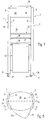
- the information surface stand 1 of the embodiment of FIGS. 7 and 8, in which Identical or comparable parts are provided with the same reference symbols, has two Information surface carrier 2 on in a position in which its arched Information carrier surfaces 8 point away from each other at a distance a arranged and by struts 36 extending between their rear sides 6 are attached to each other and stabilized.
- a base 3 for the information surface support 2 be formed by a base plate on which the Information surface carrier 2 stand.
- Base plates 3b from below and into the information surface support 2 enclosing fastening screws or pins, not shown.
- the straight and curved edges of the base plates 3b can with the associated edges of the Information surface carrier 2 be congruent.
- the base plates 3b are somewhat wider than that Information surface carrier 2, so that their curved edges the information surface carrier 2 protrude at least on the outside.
- the information surface carrier 2 can stand with the base plates 3b on the existing floor.
- Such attachments with e.g. four Wheels 37 can also be on the underside of the base plate 3a according to FIGS. 1 and 2 be provided.
- Information carrier surfaces 8 present opposite one another, which are direct or by means of the attachment parts described as a carrier of information and if necessary can also be used as storage parts.
- the struts 36 can also serve as storage parts, with between struts arranged one above the other result in 36 storage compartments.
- a further support member 38 between the information surface carriers 2.
- the outward-facing vertical visible surface of the support part 38 forms a further information carrier surface 8d, this visible surface also by one vertical axis of curvature preferably curved outward in the form of a cylindrical section is.
- the support member 38 can extend from one side to the other side of the Information surface stand 1 extending traverse. For fastening the support part 38 and also the other struts 36 still to be described, they cannot The holding elements shown serve in the mutually opposite grooves 2, 4 are fixable.
- the or one of the shelves 39 is preferably at the height of a table arranged so that it can be used as a desk 41. To get more space have, it is advantageous to extend this shelf 39 laterally so that it over the Outer contour of the information surface stand 1 protrudes and therefore because of larger Space is more accessible. In the present embodiment points the projecting section 39a of the shelf 39 has a laterally offset shape.
- this shelf 39 is also to be used as a desk if in the area between the information surface supports 2 one or more further shelves 39 are arranged one above the other.
- this shelf 39 between the top shelf 39 and the supporting part 38 has such a large vertical distance that 42 a screen of a television set or a picture / sound display device in particular for advertising lectures, is positionable.
- a Base cabinet 43 may be arranged on the underside of this shelf 39 and / or can be attached to the information surface supports 2 by the holding elements.
- the support parts 2a, 2b or the information surface support 2 preferably consist of a light material, e.g. Light metal, especially aluminum, plastic or Carton. This is preferably such a material that Extrusion can be molded.
- a light material e.g. Light metal, especially aluminum, plastic or Carton. This is preferably such a material that Extrusion can be molded.
Landscapes
- Physics & Mathematics (AREA)
- General Physics & Mathematics (AREA)
- Engineering & Computer Science (AREA)
- Theoretical Computer Science (AREA)
- Business, Economics & Management (AREA)
- Accounting & Taxation (AREA)
- Marketing (AREA)
- Devices For Indicating Variable Information By Combining Individual Elements (AREA)
Abstract
Description
Claims (25)
- Informationsflächenträger (2) mit einer im horizontalen Schnitt länglichen Querschnittform und mit wenigstens einer Informationsträgerfläche (8, 8a) an einer oder beiden Breitseiten, wobei die eine Breitseite (Br) eine um eine vertikale Krümmungsachse gewölbte Seitenfläche und die andere Breitseite (Br) eine ebene Seitenfläche aufweist, und wobei in der gewölbten Seitenfläche und/oder in der ebenen Seitenfläche wenigstens eine vertikal verlaufende hinterschnittene Nut (24) angeordnet ist bzw. sind.
- Informationsflächenträger nach Anspruch 1,
dadurch gekennzeichnet, daß die Nut (24) an der jeweiligen Breitseite mittig angeordnet ist. - Informationsflächenträger nach Anspruch 1 oder 2,
dadurch gekennzeichnet, daß er aus wenigstens zwei Tragteilen (2a, 2b) besteht, die jeweils einen Tragteilkörper (2c) mit einer im horizontalen Schnitt länglichen Querschnittsform aufweisen, und die bei aufrechtem Verlauf ihrer Breitseiten (Bv1, Bv2; Br1, Br2) und Schmalseiten (S1, S2) an einer schmalseitigen Teilungsfuge (T) durch miteinander korrespondierende Befestigungselemente (11, 12; 13, 14) aneinander befestigt sind, die an den die Teilungsfuge (T) bildenden Schmalseiten (S1, S2) der Tragteilkörper (2c) angeordnet sind und bezüglich der miteinander fluchtenden Breitseiten der Tragteilkörper (2c) nach innen versetzt sind. - Informationsflächenträger nach Anspruch 2 und 3,
dadurch gekennzeichnet, daß die wenigstens eine Nut (24) dadurch gebildet ist, daß die Ränder (Tv1, Tv2, Tr1, Tr2) der Teilungsfuge (T) an der zugehörigen Breitseite einen Abstand voneinander aufweisen. - Informationsflächenträger nach einem der vorherigen Ansprüche,
dadurch gekennzeichnet, daß der Informationsflächenträger (2) oder die Tragteilkörper (2c) jeweils durch sich aufrecht erstreckende Profile (P) gebildet sind. - Informationsflächenträger nach einem der vorherigen Ansprüche,
dadurch gekennzeichnet, daß der Informationsflächenträger (2) oder die Tragteilkörper (2c) oberseitig und/oder unterseitig jeweils durch eine Platte (25) verschlossen sind, die mit dem Informationsflächenträger (2) oder den Tragteilkörpern (2c) verbunden ist, z.B. durch von ihr abstehende Stifte, die vorzugsweise mit Klemmspannung in Aufnahmelöcher (26) am Informationsflächenträger (2) oder an den Tragteilkörpern (2c) einfassen. - Informationsflächenträger (2) mit wenigstens zwei Tragteilen (2a, 2b), die jeweils einen Tragteilkörper (2c) mit einer im horizontalen Schnitt länglichen Querschnittsform aufweisen, und die bei stehendem Verlauf ihrer Breitseiten und Schmalseiten an einer schmalseitigen Teilungsfuge (T) durch miteinander korrespondierende Befestigungselemente (11, 12; 13, 14) aneinander befestigt sind, die an den die Teilungsfuge (T) bildenden Schmalseiten der Tragteilkörper (2c) angeordnet sind und bezüglich der miteinander fluchtenden Breitseiten der Tragteilkörper (2c) nach innen versetzt sind, wobei an einer oder an beiden Breitseiten im Bereich der Teilungsfuge (T) eine hinterschnittene Nut (24) angeordnet ist bzw. sind.
- Informationsflächenträger nach Anspruch 7,
dadurch gekennzeichnet, daß die Breitseiten der Tragteilkörper (2) auf einer Seite des Informationsflächenträgers (2) gemeinsam eine um eine aufrechte Krümmungsachse gewölbte Informationsträgerfläche (8) bilden. - Informationsflächenträger nach Anspruch 8,
dadurch gekennzeichnet, daß die Breitseiten der Tragteilkörper (2c) auf der anderen Seite des Informationsflächenträgers (2) gemeinsam eine ebene Informationsträgerfläche (8a) bilden. - Informationsflächenträger nach einem der Ansprüche 7 bis 9,
dadurch gekennzeichnet, daß die Tragteilkörper (2c) im horizontalen Schnitt eine dreieckförmige Querschnittsform aufweisen. - Informationsflächenträger nach Anspruch 10,
dadurch gekennzeichnet, daß die der Teilungsfuge (T) abgewandten Ecken (7) der Dreieckform gerundet sind. - Informationsflächenträger nach einem der vorherigen Ansprüche 3 bis 11,
dadurch gekennzeichnet, daß die Tragteilkörper (2c) durch sich aufwärts erstreckende Profile (P) insbesondere Hohlprofile, gebildet sind. - Informationsflächenträger nach einem der vorherigen Ansprüche,
dadurch gekennzeichnet, daß er aus Leichtmaterial, insbesondere Leichtmetall, vorzugsweise Aluminium, oder Karton besteht. - Informationsflächenträger nach einem der vorherigen Ansprüche 2 bis 13,
dadurch gekennzeichnet, daß die der Teilungsfuge (T) zugewandten Ränder der breitseitigen Wände (16, 17) der Tragteilkörper (2c) eine die Wände (16, 17) miteinander verbindende Querwand (18) überragen. - Informationsflächenträger nach einem der vorherigen Ansprüche 3 bis 14,
dadurch gekennzeichnet, daß die Befestigungselemente (11, 12; 13, 14) eine Verrastungsvorrichtung (22) bilden. - Informationsflächenträger nach einem der Ansprüche 2 bis 15,
dadurch gekennzeichnet, daß an den breitseitigen Rändern (Tv1, Tv2, Tr1, Tr2) der Teilungsfuge (T) jeweils zwei einander gegenüberliegend angeordnete Befestigungselemente ein miteinander zusammenwirkendes Befestigungselementenpaar bilden. - Informationsflächenträger nach Anspruch 15 und 16,
dadurch gekennzeichnet, daß das eine Befestigungselementenpaar ein Gelenk (21) mit einer vertikalen Gelenkachse bilden, in dem die Tragteile (2a, 2b) schwenkbar aneinander gelagert sind, und das andere Befestigungselementenpaar die Verrastungsvorrichtung (11) bildet. - Informationsflächenträger nach Anspruch 17,
dadurch gekennzeichnet, daß von dem Befestigungselementenpaar, das das Gelenk (21) bildet, das eine Befestigungselement eine kreisbogenabschnittförmig gekrümmte Führungsnut (14c) und
das andere Befestigungselement einen entsprechend gekrümmten und mit geringem Bewegungsspiegel in die Führungsnut (14c) angeordneten Führungssteg (13c) aufweist. - Informationsflächenträger nach einem der vorherigen Ansprüche 16 bis 18,
dadurch gekennzeichnet, daß die Befestigungselemente jeweils mit einem einen Abstand von der Teilungsfuge (T) aufweisenden und nach innen abstehenden Schenkel (11a, 12a) und einen die Teilungsfuge (T) überragenden zweiten Schenkel (11b, 12b) winkelförmig geformt sind. - Informationsflächenträger nach einem der vorherigen Ansprüche 3 bis 19,
dadurch gekennzeichnet, daß die Verrastungsvorrichtung (22) an den einander zugewandten Seiten von einander überlappenden Befestigungselementen (11b, 12b) angeordnet ist. - Informationsflächenträger nach einem der vorherigen Ansprüche,
dadurch gekennzeichnet, daß wenigstens ein zusätzlicher Hilfsinformationsflächenträger in Form eines Anbauteiles (25) vorgesehen ist, der durch ein in die Nut (24) eingesetztes Haltemittel höheneinstellbar am Informationsflächenträger (2) befestigbar ist und eine zusätzliche Informationsträgerfläche (8b) und/oder ein vorzugsweise durch einen Tragschenkel (32b) gebildetes Tragelement für Informationsgegenstände aufweist. - Informationsflächenträger nach einem der vorherigen Ansprüche,
dadurch gekennzeichnet, daß er mit einer Basis (3), auf der er stehend befestigt ist, einen Ständer bildet, der vorzugsweise mit an der Basis (3) angeordneten Rädern (37) verfahrbar ist. - Informationsflächenträger nach Anspruch 22,
dadurch gekennzeichnet, daß zwei Informationsflächenträger (2) in einer Position auf der Basis (3) angeordnet sind, in der ihre ebenen Breitseiten (Br) einander zugewandt sind und einen horizontalen Abstand voneinander aufweisen. - Informationsflächenträger nach Anspruch 23,
dadurch gekennzeichnet, daß zwischen den Informationsflächenträgern (2) wenigstens ein Fachboden (39) oder mehrere Fachböden (39) übereinander angeordnet sind. - Informationsflächenträger nach Anspruch 24,
dadurch gekennzeichnet, daß ein Fachboden (39) in Höhe eines Schreibtisches (41) angeordnet ist und vorzugsweise seitlich absteht.
Applications Claiming Priority (2)
| Application Number | Priority Date | Filing Date | Title |
|---|---|---|---|
| DE20015397U | 2000-09-06 | ||
| DE20015397U DE20015397U1 (de) | 2000-09-06 | 2000-09-06 | Informationsflächenträger |
Publications (2)
| Publication Number | Publication Date |
|---|---|
| EP1187084A2 true EP1187084A2 (de) | 2002-03-13 |
| EP1187084A3 EP1187084A3 (de) | 2004-04-21 |
Family
ID=7946124
Family Applications (1)
| Application Number | Title | Priority Date | Filing Date |
|---|---|---|---|
| EP01121267A Withdrawn EP1187084A3 (de) | 2000-09-06 | 2001-09-05 | Informationsflächenträger |
Country Status (2)
| Country | Link |
|---|---|
| EP (1) | EP1187084A3 (de) |
| DE (1) | DE20015397U1 (de) |
Family Cites Families (9)
| Publication number | Priority date | Publication date | Assignee | Title |
|---|---|---|---|---|
| GB2114351B (en) | 1981-10-28 | 1984-12-05 | Anglia Signs And Displays Limi | Sign box |
| DE9001489U1 (de) * | 1990-02-09 | 1990-04-12 | Juhr, Heinz, 71254 Ditzingen | Vorrichtung zur Ausstellung von ggfs. durchscheinenden Informationsträgern |
| DE9104760U1 (de) * | 1991-04-18 | 1992-08-20 | Mühl, Paul, 8000 München | Aufstellbare Säule |
| DE4309544C1 (de) | 1993-03-24 | 1994-03-17 | Hans Victor Schoenfeld | Schaukastenbauelement |
| DE29607012U1 (de) | 1996-04-18 | 1996-06-27 | Wolk GmbH, 42117 Wuppertal | Informationsständer |
| DE29614775U1 (de) | 1996-08-26 | 1996-11-28 | Deutsche Plakat-Werbung GmbH & Co., 56070 Koblenz | Aufklappbarer Rahmen zur Aufnahme von Plakaten u.dgl. |
| DE29702517U1 (de) * | 1997-02-14 | 1997-05-07 | Jahnke, Marion, 24114 Kiel | Schautafel |
| FR2776105B1 (fr) * | 1999-03-12 | 2002-12-06 | Hotel Francois L | Presentoir pliable |
| DE29905260U1 (de) | 1999-03-17 | 1999-11-04 | Heinz Werbung Metall- und Fassadenbau GmbH, 04936 Kolochau | Werbeträger |
-
2000
- 2000-09-06 DE DE20015397U patent/DE20015397U1/de not_active Expired - Lifetime
-
2001
- 2001-09-05 EP EP01121267A patent/EP1187084A3/de not_active Withdrawn
Also Published As
| Publication number | Publication date |
|---|---|
| EP1187084A3 (de) | 2004-04-21 |
| DE20015397U1 (de) | 2001-02-15 |
Similar Documents
| Publication | Publication Date | Title |
|---|---|---|
| EP2066198B1 (de) | Präsentationsanordnung | |
| DE3124391C2 (de) | Koffer | |
| DE10297217T5 (de) | Kastengestellanordnung | |
| EP3098362B1 (de) | System zum aufbau eines rahmenfachwerks | |
| DE19703754A1 (de) | Ständer | |
| DE2305609C3 (de) | ||
| WO1994007704A1 (de) | Aufnahmevorrichtung für rollen und gleiter | |
| WO1994020762A1 (de) | Profil-system | |
| EP3709856A1 (de) | Reinigungsfahrwagen und verfahren zu dessen montage | |
| WO2004019304A2 (de) | Anzeigeeinrichtung für ein display | |
| EP1187084A2 (de) | Informationsflächenträger | |
| EP0801374B1 (de) | Träger für Werbe- und Kommunikationsmittel | |
| DE3129573C2 (de) | Bausatz für Möbel, insbesondere Anbaumöbel | |
| DE102004033876A1 (de) | Dreidimensionales Struktursystem | |
| DE7617050U1 (de) | Zerlegbarer schrank | |
| DE19717618A1 (de) | Tisch mit zwei übereinander angeordneten Tischplatten, zwischen denen Objekte und Informationsträger integriert werden können | |
| DE3530391C1 (de) | Bauelement als Teil von Präsentationsaufbauten, wie Ausstellungsständen oder dergleichen kurzlebigen Aufbauten | |
| DE4308448C2 (de) | Bausatz zum Nachrüsten eines Schreib- oder Arbeitstisches | |
| EP1001399B1 (de) | Vorrichtung zur Befestigung einer selbsttragenden Kassette an einer Trägerplatte | |
| DE19604729C2 (de) | Präsentationsvorrichtung | |
| DE3225113A1 (de) | Wandelement fuer praesentationswaende, austellungsstaende und dergleichen aufbauten | |
| DE3144934A1 (de) | Verkaufsstand oder regal mit auf einem sockelkasten angeordnetem aufsatz | |
| DE10160740A1 (de) | Bausatz zur Errichtung eines Präsentationsstands für eine Messe oder dgl. | |
| DE102012107524A1 (de) | Einrichtung zur Präsentation und/oder Aufnahme von Gegenständen | |
| DE9416629U1 (de) | Variables Displaysystem |
Legal Events
| Date | Code | Title | Description |
|---|---|---|---|
| PUAI | Public reference made under article 153(3) epc to a published international application that has entered the european phase |
Free format text: ORIGINAL CODE: 0009012 |
|
| AK | Designated contracting states |
Kind code of ref document: A2 Designated state(s): AT BE CH CY DE DK ES FI FR GB GR IE IT LI LU MC NL PT SE TR |
|
| AX | Request for extension of the european patent |
Free format text: AL;LT;LV;MK;RO;SI |
|
| PUAL | Search report despatched |
Free format text: ORIGINAL CODE: 0009013 |
|
| AK | Designated contracting states |
Kind code of ref document: A3 Designated state(s): AT BE CH CY DE DK ES FI FR GB GR IE IT LI LU MC NL PT SE TR |
|
| AX | Request for extension of the european patent |
Extension state: AL LT LV MK RO SI |
|
| RIC1 | Information provided on ipc code assigned before grant |
Ipc: 7G 09F 15/02 B Ipc: 7G 09F 7/18 A |
|
| 17P | Request for examination filed |
Effective date: 20040625 |
|
| 17Q | First examination report despatched |
Effective date: 20040802 |
|
| AKX | Designation fees paid |
Designated state(s): AT BE CH CY DE DK ES FI FR GB GR IE IT LI LU MC NL PT SE TR |
|
| GRAP | Despatch of communication of intention to grant a patent |
Free format text: ORIGINAL CODE: EPIDOSNIGR1 |
|
| STAA | Information on the status of an ep patent application or granted ep patent |
Free format text: STATUS: THE APPLICATION IS DEEMED TO BE WITHDRAWN |
|
| 18D | Application deemed to be withdrawn |
Effective date: 20100310 |