EP1186854A2 - Beleuchtungs- und Abbildungseinrichtung für mehrere Spektralbereiche und Koordinatenmessmaschine mit einer Beleuchtungs- und Abbildungseinrichtung für mehrere Spektralbereiche - Google Patents
Beleuchtungs- und Abbildungseinrichtung für mehrere Spektralbereiche und Koordinatenmessmaschine mit einer Beleuchtungs- und Abbildungseinrichtung für mehrere Spektralbereiche Download PDFInfo
- Publication number
- EP1186854A2 EP1186854A2 EP01120206A EP01120206A EP1186854A2 EP 1186854 A2 EP1186854 A2 EP 1186854A2 EP 01120206 A EP01120206 A EP 01120206A EP 01120206 A EP01120206 A EP 01120206A EP 1186854 A2 EP1186854 A2 EP 1186854A2
- Authority
- EP
- European Patent Office
- Prior art keywords
- beam splitter
- illumination
- group
- imaging device
- wavelength
- Prior art date
- Legal status (The legal status is an assumption and is not a legal conclusion. Google has not performed a legal analysis and makes no representation as to the accuracy of the status listed.)
- Withdrawn
Links
Images


Classifications
-
- G—PHYSICS
- G01—MEASURING; TESTING
- G01B—MEASURING LENGTH, THICKNESS OR SIMILAR LINEAR DIMENSIONS; MEASURING ANGLES; MEASURING AREAS; MEASURING IRREGULARITIES OF SURFACES OR CONTOURS
- G01B11/00—Measuring arrangements characterised by the use of optical techniques
- G01B11/002—Measuring arrangements characterised by the use of optical techniques for measuring two or more coordinates
Definitions
- the invention relates to a lighting and imaging device for multiple spectral ranges.
- the invention further relates to a coordinate measuring machine with a lighting and imaging device for multiple spectral ranges.
- a coordinate measuring machine is in the German patent application DE-A-198 19,492.
- the sample is illuminated in reflected light by a light source in the near UV spectral range.
- detection Detector device provided, the imaging beam path via a Beam splitter coupled into the optical axis defined by a lens becomes. This system does not allow simultaneous lighting and analysis of the sample to be examined with several spectral ranges or the Evaluation according to separate spectral ranges.
- the invention has for its object a lighting and To create imaging unit that is suitable for multiple spectral ranges.
- Another object of the invention is to provide a coordinate measuring machine create that is suitable to measure very fine structures on a sample and thereby the sample to be examined with several spectral ranges irradiate.
- the objective task is solved with a coordinate measuring machine an illumination and imaging device for several spectral ranges, which defines an optical axis, and one perpendicular and relative to optical axis interferometrically measurable, movable measuring table for Taking a sample.
- An advantage of the invention is that the lighting and Imaging device is provided with a beam splitter module which in the optical axis of the lens used to image the examining sample is arranged. In doing so, all figures and Illumination beam paths guided along the optical axis. in addition comes that several light sources are provided, one of each Illumination beam path goes out. The light sources can be such be designed to light in a very specific way Send out the wavelength range. As already mentioned, there are also several Detectors are provided, each of which has an imaging beam path is assigned, the illumination beam paths and the Imaging beam paths have a common optical path, in which the beam splitter module is arranged. This allows the different detectors selectively with different ones Wavelength ranges are applied.
- the lighting and Use imaging device in a coordinate measuring machine.
- the Coordinate measuring machine must be designed so that all possible disruptive influences are largely excluded, which is a highly accurate Disrupt measurement. Only then is the measurement of the position of edges on Structures with an accuracy of a few nanometers possible.
- Through the Illumination and imaging device according to the invention must despite multiple light sources and detectors not switched or one mechanical displacement of the optical path can be initiated. These processes would create turbulence or heat, which the Influence measurement in an undefined way.
- the use of the Beam splitter module in the lighting and imaging device allows it that all lighting and imaging beam paths through just one Be guided objectively.
- the lighting and imaging device is for suitable for several spectral ranges.
- the lens is followed by a beam splitter module with four beam splitters, each of which is arranged in pairs in a beam splitter group.
- the first beam splitter in each group is a fifty / fifty splitter and the second beam splitter is a dichroic splitter.
- the properties of the beam splitters with respect to the wavelengths are such that the first beam splitter group only transmits light with a wavelength above a first wavelength ⁇ 1 , and that the second beam splitter group only transmits light with a wavelength below a second wavelength ⁇ 2 .
- a detector is arranged after the beam splitter module in the transmitted beam path, the detector detecting in the wavelength range between ⁇ 1 and ⁇ 2 .
- the three different spectral ranges mentioned are available on these.
- the lens is corrected for diffraction limited in the range between a lower wavelength ⁇ min smaller than ⁇ 1 and an upper wavelength ⁇ max larger than ⁇ 2 .
- FIG. 1 shows an exemplary embodiment of a coordinate measuring machine 1 a combined incident and transmitted light lighting, which a comprises lighting and imaging device 2 according to the invention.
- the coordinate measuring machine shown has a granite block 23, which is mounted on vibration dampers 24, 25.
- a measuring table 26 designed as a frame on air bearings 27, 28 in the x and y directions (indicated by two arrows in the drawing) sliding displaceable.
- the frame of the measuring table 26 advantageously consists made of a glass ceramic with a low thermal expansion coefficient.
- the drive elements for moving the measuring table 26 are not shown.
- the position of the measuring table 26 is determined using a laser interferometer system 29 measured in the x and y directions.
- sample 30 is inserted into the measuring table 26.
- Sample 30 is e.g. made of quartz glass. Structures 31 are applied to the sample surface.
- the measuring table 26 is designed as a frame, the sample 30 can also from be examined from below.
- the Illumination and imaging device 2 is about an optical axis 20 arranged around. Focusing is along the optical axis 20 in the z direction possible.
- the lighting and imaging device 2 consists of a beam splitter module 32 and several detectors 34 and also a plurality of lighting devices 35.
- the Position of a structure 31 determined as coordinates on the sample 30.
- a transmitted light illumination device In the granite block 23 there is also a transmitted light illumination device a height-adjustable condenser 17 and a light source 7 are used.
- a transmitted light illumination beam path with a goes from the light source 1 optical axis 2.
- the recorded Light is coupled into an optical waveguide using the coupling optics 3.
- an optical fiber bundle 4 is used.
- a coupling optic 5 which is preferably designed as an achromatic, collimates the light emitted by the fiber bundle 4.
- the optical axis of the condenser 17 is aligned with the optical axis 20.
- the height adjustment of the condenser 17 is used to adapt the illumination beams to be directed onto the structure 31 to different optical thicknesses of masks 30.
- the condenser head can extend in particular into the open part of the measuring table frame. To protect against damage when the measuring table 26 is displaced over the entire mask surface, the condenser 26 can also be pulled under the surface of the granite block 23.
- the light source 7 and the multiple Illumination devices 35 of the illumination and imaging device 2 can be switched on independently of one another.
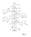
- Fig. 2 shows a special embodiment of the lighting and Imaging device 2, which is suitable for several spectral ranges and an image of high optical quality for several spectral ranges allows.
- the lighting and imaging device 2 comprises a Objective 21, which is arranged in the optical axis 20 or the optical Axis 20 defined.
- a beam splitter module 32 is attached to the objective 20 downstream, which is essentially centered around the optical axis 20 is arranged.
- the lighting and imaging device also includes 2, multiple detectors 34 and multiple light sources 35.
- the beam splitter module 32 consists of several beam splitters 10, 11, 12 and 13 which are around and along the optical axis 20 are arranged.
- Embodiments are based on the lens 21, the first and the respective second beam splitters 10 and 11 in a first group 14 and the third and fourth beam splitters 12 and 13 arranged in a second group 15. It is the first beam splitter 10 and 12 of each group 14 and 15 as fifty / fifty splitters educated.
- the second beam splitter 11 and 13 of each group 14 and 15 is designed as a dichroic divider.
- the first beam splitter 10 of the first Group 14 is assigned to a detector 34, which in an associated Imaging beam path 34a is arranged.
- This beam splitter 10 is used for Decoupling the light from the common optical path in the Beam splitter module 32.
- the common optical path in Beam splitter module 32 is identical to the optical axis 20.
- the second Beam splitter 11 of the first group 14 is assigned to a light source 35, which in an associated illumination beam path 35a is arranged.
- the first Beam splitter 12 of the second group 15 is also a light source 35 assigned in an associated illumination beam path 35b is arranged.
- the second beam splitter 13 of the second group 15 is one Detector 34 and another light source 35 assigned.
- the detector 34 defines an imaging beam path 34b and the further light source 35 defines an illumination beam path 35c.
- the first beam splitter 10 of the first A measurement camera is assigned to the group.
- the measuring camera is a special one Design of the detector 34.
- the measuring camera receives this from the sample 30 outgoing light after only one beam splitting. This is required to possible imaging errors due to multiple beam splitting as low as to keep possible, since the measurement of the structures by means of the measuring camera 31 on the sample 30 is made. Any falsification of the measurement due to aberrations is excluded.
- the second beam splitter 11 of the first group 14 is a measurement illumination as the light source 35 assigned to light in a wavelength range from 365 to 405 nm sending out.
- the first beam splitter 12 of the second group 15 is as Light source 35 assigned an overview lighting, the light in one Wavelength range from 480 to 700 nm emits.
- the second beam splitter 13 of the second group 15 as a detector 34 an alignment device assigned for the alignment of the sample in terms of lighting and Imaging device 2 is responsible.
- this beam splitter is 13 assigned a further light source 34, which is designed as a laser autofocus. Laser auto focus works with wavelengths above 800 nm.
- the beam splitters are arranged accordingly depending on the wavelength used to measure the sample 30.
- the first group 14 of the beam splitters 10 and 11 is configured such that only light with a wavelength above a first wavelength ⁇ 1 is transmitted.
- the second group 15, consisting of the beam splitters 12 and 13, is designed such that only light with a wavelength below a second wavelength ⁇ 2 is transmitted.
- behind the second group 15 there is a detector 34 in the imaging beam path 34b of the beam splitter module 32, the detector 34 detecting in the wavelength range between ⁇ 1 and ⁇ 2 .
- the objective is corrected between a lower wavelength ⁇ min smaller than ⁇ 1 and an upper wavelength ⁇ max larger than ⁇ 2 .
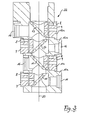
- FIG. 3 shows an embodiment of a structural configuration of a Beam splitter module 32 shown.
- the beam splitter module 32 defines one lower part, to which the lens 21 (see FIG. 2) connects. Further defines the beam splitter module 32 an upper part in which a bore is formed, which is designed to hold an optical system (not shown) is.
- a detector 34 is assigned to the optics, which in this embodiment is an alignment device.
- Each of the beam splitters 10, 11, 12 and 13 is in a bracket firmly inserted.
- the beam splitter is with the Reference numeral 10 in a first holder 10a, the beam splitter with the Reference numeral 11 in a second holder 11a, the beam splitter with the Reference numeral 12 in a third holder 12a and the beam splitter with the Reference numeral 13 used in a fourth holder 13a.
- Each of the Mounts 10a, 11a, 12a and 13a has a flange 16 on which optical elements can be attached that the light to or from the Brackets 10a, 11a, 12a and 13a for detectors 34 or light sources 35 to lead.
- an adjusting element 9 is provided, in which a bore 8 for a Adjusting screw (not shown) is attached, which the setting of the Allows beam splitter with respect to the optical axis 20. It's headed for it make sure that the beam splitters with the reference numerals 10 and 12 each by 45 ° are inclined with respect to the optical axis. The beam splitters are also included the reference numerals 11 and 13 each by - 45 ° compared to the optical Axis inclined. A corresponding mirror-inverted arrangement is possible and of course for every specialist.
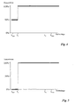
- the optical properties of the beam splitters 10, 11, 12 and 13 are shown in FIGS. 4 to 7.
- the sequence of the arrangement of the beam splitters, starting from the objective 21, in the beam splitter module 32 or their optical properties are only an exemplary embodiment and should not be interpreted as a limitation of the invention.
- the beam splitter 10 immediately following the objective 21 is designed as a fifty / fifty beam splitter. This beam splitter reflects 50% of the light in the direction of the flange 16 and the other 50% are transmitted along the optical axis 20.
- the beam splitter 12 shows the properties of the beam splitter 12 with regard to the wavelengths.
- ⁇ max 900 nm, the beam splitter 12 is completely transparent.
- the figures for the wavelengths are only to be regarded as one possible embodiment. The selection of other wavelength ranges lies in the inventive ability of a person skilled in the art.
Landscapes
- Physics & Mathematics (AREA)
- General Physics & Mathematics (AREA)
- Length Measuring Devices By Optical Means (AREA)
- Exposure Of Semiconductors, Excluding Electron Or Ion Beam Exposure (AREA)
Abstract
Description
- einem Objektiv das eine optische Achse definiert,
- einem Strahlteilermodul das in der optischen Achse angeordnet ist,
- mehreren Lichtquellen von denen jeweils ein Beleuchtungsstrahlengang ausgeht,
- mehreren Detektoren denen jeweils ein Abbildungsstrahlengang zugeordnet ist, wobei die Beleuchtungsstrahlengänge und die Abbildungsstrahlengänge eine gemeinsame optische Wegstrecke aufweisen, in der das Strahlteilermodul angeordnet ist.
- Fig. 1
- eine schematische Darstellung einer Koordinatenmessmaschine mit der erfindungsgemäßen Beleuchtungs- und Abbildungseinrichtung;
- Fig. 2
- ein schematische Darstellung der Beleuchtungs- und Abbildungseinrichtung;
- Fig. 3
- eine konstruktive Ausgestaltung des Mehrfach-Strahlteilermoduls, das Teil der erfinderischen Beleuchtungs- und Abbildungseinrichtung ist;
- Fig. 4
- ein Diagramm der optischen Eigenschaften des ersten Strahlteilers der ersten Gruppe des Strahlteilermoduls;
- Fig. 5
- ein Diagramm der optischen Eigenschaften des zweiten Strahlteilers der ersten Gruppe des Strahlteilermoduls;
- Fig. 6
- ein Diagramm die optischen Eigenschaften des ersten Strahlteilers der zweiten Gruppe des Strahlteilermoduls; und
- Fig. 7
- ein Diagramm der optischen Eigenschaften des zweiten Strahlteilers der zweiten Gruppe des Strahlteilermoduls.
Beleuchtungseinrichtungen 35 der Beleuchtungs- und Abbildungseinrichtung 2 sind voneinander unabhängig einschaltbar.
- 1
- Koordinatenmessmaschine
- 2
- Beleuchtungs- und Abbildungseinrichtung
- 3
- Einkoppeloptik
- 4
- Faserbündel
- 5
- Auskoppeloptik
- 7
- Lichtquelle
- 8
- Bohrung
- 9
- Verstellelement
- 10
- Strahlteiler
- 10a
- erste Halterung
- 11
- Strahlteiler
- 11a
- zweite Halterung
- 12
- Strahlteiler
- 12a
- dritte Halterung
- 13
- Strahlteiler
- 13a
- vierte Halterung
- 14
- erste Gruppe
- 15
- zweite Gruppe
- 16
- Flansch
- 17
- höhenverstellbarer Kondensor
- 20
- optische Achse
- 21
- Objektiv
- 24
- Schwingungsdämpfer
- 25
- Schwingungsdämpfer
- 26
- Messtisch
- 27
- Luftlager
- 28
- Luftlager
- 29
- Laser-Interferometer-System
- 30
- Probe
- 31
- Strukturen
- 32
- Strahlteilermodul
- 33
- Alignmenteinrichtung
- 34
- Detektoren
- 34a
- Abbildungsstrahlengang
- 34b
- Abbildungsstrahlengang
- 35
- Lichtquellen
- 35a
- Beleuchtungsstrahlengang
- 35b
- Beleuchtungsstrahlengang
- 35c
- Beleuchtungsstrahlengang
Claims (10)
- Beleuchtungs- und Abbildungseinrichtung (2) für mehrere Spektralbereiche miteinem Objektiv (21), das eine optische Achse (20) definiert,einem Strahlteilermodul (32), das in der optischen Asche (20) angeordnet ist,mehreren Lichtquellen (35), von denen jeweils ein Beleuchtungsstrahlengang (35a, 35b, 35c) ausgeht,mehreren Detektoren (34), denen jeweils ein Abbildungsstrahlengang (34a, 34b) zugeordnet ist, wobei die Beleuchtungsstrahlengänge (35a, 35b, 35c) und die Abbildungsstrahlengänge(34a, 34b) eine gemeinsame optische Wegstrecke aufweisen, in der das Strahlteilermodul (32) angeordnet ist.
- Beleuchtungs- und Abbildungseinrichtung (2) nach Anspruch 1, dadurch gekennzeichnet, dass in dem Strahlteilermodul (32) mehrere Strahlteiler (10, 11, 12, 13) angeordnet sind, die entweder je einer der Lichtquellen (35) zugeordnet und in deren Beleuchtungsstrahlengang (35a, 35b, 35c) angeordnet sind, um diese in die gemeinsame optische Wegstrecke einzukoppeln, oder die je einem der Detektoren (34) zugeordnet und in dem zugehörigen Abbildungsstrahlengang (34a, 34b) angeordnet sind, um diesen aus der gemeinsamen optischen Wegstrecke auszukoppeln.
- Beleuchtungs- und Abbildungseinrichtung (2) nach Anspruch 2, dadurch gekennzeichnet, dass ausgehend vom Objektiv (21) jeweils zwei Strahlteiler (10; 11 und 12; 13) paarweise in einer Gruppe (14, 15) angeordnet sind, wobei der erste Strahlteiler (10) jeder Gruppe ein fünfzig/fünfzig-Teiler ist und der zweite Strahlteiler (11) jeder Gruppe ein dichroitischer Teiler ist.
- Beleuchtungs- und Abbildungseinrichtung (2) nach Anspruch 3, dadurch gekennzeichnet, dass ausgehend vom Objektiv (21) die erste Strahlteilergruppe (14) nur Licht mit einer Wellenlänge oberhalb einer ersten Wellenlänge λ1 durchlässt, dass die zweite Strahlteilergruppe (15) nur Licht mit einer Wellenlänge unterhalb einer zweiten Wellenlänge λ2 durchlässt und dass hinter der zweiten Gruppe (15) ein Detektor (34) nach dem Strahlteilermodul (13) im transmittierten Strahlengang angeordnet ist, wobei der Detektor (34) im Wellenlängenbereich zwischen λ1 und λ2 detektiert.
- Beleuchtungs- und Abbildungseinrichtung (2) nach Anspruch 4, dadurch gekennzeichnet, dass das Objektiv (21) beugungsbegrenzt im Bereich zwischen einer unteren Wellenlänge λmin kleiner als λ1 und einer oberen Wellenlänge λmax größer als λ2 korrigiert ist.
- Koordinatenmessmaschine (1) mit einer Beleuchtungs- und Abbildungseinrichtung (2) nach Anspruch 1 für mehrere Spektralbereiche, die eine optische Achse (20) definiert und einem senkrecht und relativ zur optischen Achse (20) interferometrisch messbaren, verschiebbarem Messtisch (26) zur Aufnahme einer Probe (30).
- Koordinatenmessmaschine (1) nach Anspruch 6 , dadurch gekennzeichnet, dass die Beleuchtungs- und Abbildungseinrichtung (2) für mehrere Spektralbereicheumfasst.ein Objektiv (21), das eine optische Achse (20) definiert,ein Strahlteilermodul (32), das in der optischen Asche (20) angeordnet ist,mehrere Lichtquellen (35), von denen jeweils ein Beleuchtungsstrahlengang (35a, 35b, 35c) ausgeht, undmehrere Detektoren (34), denen jeweils ein Abbildungsstrahlengang (34a, 34b) zugeordnet ist, wobei die Beleuchtungsstrahlengänge (35a, 35b, 35c) und die Abbildungsstrahlengänge (34a, 34b) eine gemeinsame optische Wegstrecke aufweisen, in der das Strahlteilermodul (32) angeordnet ist,
- Koordinatenmessmaschine (1) nach Anspruch 7 , dadurch gekennzeichnet, dass in dem Strahlteilermodul (32) mehrere Strahlteiler (10, 11, 12, 13) angeordnet sind, die entweder je einer der Lichtquellen (35) zugeordnet und in deren Beleuchtungsstrahlengang (35a, 35b, 35c) angeordnet sind, um diese in die gemeinsame optische Wegstrecke einzukoppeln, oder die je einem der Detektoren (34) zugeordnet und in dem zugehörigen Abbildungsstrahlengang (34a, 34b) angeordnet sind, um diesen aus der gemeinsamen optischen Wegstrecke auszukoppeln.
- Koordinatenmessmaschine nach Anspruch 8 , dadurch gekennzeichnet,dass ausgehend vom Objektiv (21) jeweils zwei Strahlteiler (10; 11 und 12; 13) paarweise in einer Gruppe (14, 15) angeordnet sind, wobei der erste Strahlteiler (10) jeder Gruppe ein fünfzig/fünfzig-Teiler ist und der zweite Strahlteiler (11) jeder Gruppe ein dichroitischer Teiler istund dass ausgehend vom Objektiv (21) die erste Strahlteilergruppe (14) nur Licht mit einer Wellenlänge oberhalb von λ1 durchlässt, dass die zweite Strahlteilergruppe (15) nur Licht mit einer Wellenlänge unterhalb von λ2 durchlässt und dass hinter der zweiten Gruppe (15) ein Detektor (34) nach dem Strahlteilermodul (32) im transmittierten Strahlengang angeordnet ist, wobei der Detektor (34) im Wellenlängenbereich zwischen λ1 und λ2 detektiert.
- Koordinatenmessmaschine (1) nach Anspruch 6 , dadurch gekennzeichnet,dass die Beleuchtungs- und Abbildungseinrichtung (2) eine Messeinrichtung, eine Alignmenteinrichtung und eine Autofocuseinrichtung umfasst.und dass der Messeinrichtung der Wellenlängenbereich unterhalb λ1 zugeordnet ist, der Alignmenteinrichtung der Wellenlängenbereich zwischen λ1 und λ2 zugeordnet ist und der Autofocuseinrichtung der Wellenlängenbereich oberhalb λ2 zugeordnet ist.
Applications Claiming Priority (2)
| Application Number | Priority Date | Filing Date | Title |
|---|---|---|---|
| DE10042140 | 2000-08-28 | ||
| DE10042140A DE10042140A1 (de) | 2000-08-28 | 2000-08-28 | Beleuchtungs- und Abbildungseinrichtung für mehrere Spektralbereiche und Koordinatenmessmaschine mit einer Beleuchtungs- und Abbildungseinrichtung für mehrere Spektralbereiche |
Publications (2)
| Publication Number | Publication Date |
|---|---|
| EP1186854A2 true EP1186854A2 (de) | 2002-03-13 |
| EP1186854A3 EP1186854A3 (de) | 2003-03-26 |
Family
ID=7653999
Family Applications (1)
| Application Number | Title | Priority Date | Filing Date |
|---|---|---|---|
| EP01120206A Withdrawn EP1186854A3 (de) | 2000-08-28 | 2001-08-23 | Beleuchtungs- und Abbildungseinrichtung für mehrere Spektralbereiche und Koordinatenmessmaschine mit einer Beleuchtungs- und Abbildungseinrichtung für mehrere Spektralbereiche |
Country Status (5)
| Country | Link |
|---|---|
| US (1) | US6542251B2 (de) |
| EP (1) | EP1186854A3 (de) |
| JP (1) | JP4035303B2 (de) |
| DE (1) | DE10042140A1 (de) |
| TW (1) | TW479129B (de) |
Families Citing this family (18)
| Publication number | Priority date | Publication date | Assignee | Title |
|---|---|---|---|---|
| AU2002248163A1 (en) * | 2000-12-01 | 2002-08-12 | Auburn University | High-resolution optical microscope |
| US6992819B2 (en) | 2000-12-01 | 2006-01-31 | Auburn University | High-resolution optical microscope for quick detection of pathogens |
| US6603543B1 (en) | 2001-02-01 | 2003-08-05 | Advanced Micro Devices, Inc. | Inspection system with enhanced contrast |
| US6608321B1 (en) * | 2001-02-01 | 2003-08-19 | Advanced Micro Devices, Inc. | Differential wavelength inspection system |
| US6771043B2 (en) * | 2001-05-09 | 2004-08-03 | Makita Corporation | Power tools |
| US20040082859A1 (en) | 2002-07-01 | 2004-04-29 | Alan Schaer | Method and apparatus employing ultrasound energy to treat body sphincters |
| CN1764419A (zh) * | 2003-02-20 | 2006-04-26 | 普罗里森姆股份有限公司 | 心脏消融装置 |
| DE10311286A1 (de) | 2003-03-14 | 2004-09-23 | Leica Microsystems Semiconductor Gmbh | Beleuchtungsvorrichtung für ein optisches System |
| WO2007136566A2 (en) | 2006-05-19 | 2007-11-29 | Prorhythm, Inc. | Ablation device with optimized input power profile and method of using the same |
| US7656540B2 (en) * | 2006-12-06 | 2010-02-02 | Applied Kiietics, Inc. | Apparatus and method for measuring suspension and head assemblies |
| US8582113B2 (en) | 2007-02-13 | 2013-11-12 | Kla-Tencor Mie Gmbh | Device for determining the position of at least one structure on an object, use of an illumination apparatus with the device and use of protective gas with the device |
| DE102007049133A1 (de) * | 2007-02-13 | 2008-08-21 | Vistec Semiconductor Systems Gmbh | Vorrichtung zur Bestimmung der Position mindestens einer Struktur auf einem Objekt, Verwendung einer Beleuchtungseinrichtung für die Vorrichtung und Verwendung von Schutzgas für die Vorrichtung |
| US8974445B2 (en) | 2009-01-09 | 2015-03-10 | Recor Medical, Inc. | Methods and apparatus for treatment of cardiac valve insufficiency |
| US20100295919A1 (en) * | 2009-05-21 | 2010-11-25 | Palo Alto Research Center Incorporated | Multiple Integrated Multi-Beam Laser Scanning System |
| DE102009044294A1 (de) * | 2009-10-20 | 2011-05-05 | Kla-Tencor Mie Gmbh | Koordinatenmessmaschine zur Bestimmung der Lage von Strukturen auf einer Maske |
| DE102011008655A1 (de) | 2011-01-14 | 2012-07-19 | Inb Vision Ag | Vorrichtung und Verfahren zur dreidimensionalen optischen Vermessung von Oberflächen |
| DE102012014768B4 (de) | 2012-07-23 | 2014-03-20 | Carl Zeiss Sms Gmbh | Mikroskop mit einer Übersichtsoptik |
| DE102014222271B4 (de) * | 2014-10-31 | 2017-02-02 | Carl Zeiss Smt Gmbh | Maskeninspektionssystem zur Inspektion von Lithographiemasken |
Family Cites Families (11)
| Publication number | Priority date | Publication date | Assignee | Title |
|---|---|---|---|---|
| DE2851750B1 (de) * | 1978-11-30 | 1980-03-06 | Ibm Deutschland | Verfahren und Vorrichtung zur Messung der Ebenheit der Rauhigkeit oder des Kruemmungsradius einer Messflaeche |
| JPS61219802A (ja) * | 1985-03-27 | 1986-09-30 | Hitachi Ltd | 変位の光学的測定装置 |
| JP2683075B2 (ja) * | 1988-12-23 | 1997-11-26 | キヤノン株式会社 | 半導体製造装置及び方法 |
| US5048946A (en) * | 1990-05-15 | 1991-09-17 | Phoenix Laser Systems, Inc. | Spectral division of reflected light in complex optical diagnostic and therapeutic systems |
| JP2949179B2 (ja) * | 1990-07-09 | 1999-09-13 | 群馬県 | 非接触式形状測定装置及び形状測定法 |
| US5528368A (en) * | 1992-03-06 | 1996-06-18 | The United States Of America As Represented By The Department Of Health And Human Services | Spectroscopic imaging device employing imaging quality spectral filters |
| JP3284659B2 (ja) * | 1993-04-09 | 2002-05-20 | 株式会社フジクラ | 波長多重光通信用光スイッチング装置 |
| JP3413967B2 (ja) * | 1994-06-08 | 2003-06-09 | 株式会社ニコン | 蛍光顕微鏡 |
| JPH09229628A (ja) * | 1996-02-21 | 1997-09-05 | Nikon Corp | 位置検出方法及びその装置 |
| DE19819492A1 (de) * | 1998-04-30 | 1999-11-11 | Leica Microsystems | Meßgerät zur Vermessung von Strukturen auf einem transparenten Substrat |
| JP2000074618A (ja) * | 1998-08-27 | 2000-03-14 | Fuji Xerox Co Ltd | 干渉計測方法および干渉計測装置 |
-
2000
- 2000-08-28 DE DE10042140A patent/DE10042140A1/de not_active Ceased
-
2001
- 2001-08-20 JP JP2001249071A patent/JP4035303B2/ja not_active Expired - Lifetime
- 2001-08-22 TW TW090120604A patent/TW479129B/zh not_active IP Right Cessation
- 2001-08-23 EP EP01120206A patent/EP1186854A3/de not_active Withdrawn
- 2001-08-23 US US09/934,686 patent/US6542251B2/en not_active Expired - Lifetime
Also Published As
| Publication number | Publication date |
|---|---|
| EP1186854A3 (de) | 2003-03-26 |
| US6542251B2 (en) | 2003-04-01 |
| DE10042140A1 (de) | 2002-03-14 |
| JP2002148557A (ja) | 2002-05-22 |
| JP4035303B2 (ja) | 2008-01-23 |
| TW479129B (en) | 2002-03-11 |
| US20020027663A1 (en) | 2002-03-07 |
Similar Documents
| Publication | Publication Date | Title |
|---|---|---|
| DE10042140A1 (de) | Beleuchtungs- und Abbildungseinrichtung für mehrere Spektralbereiche und Koordinatenmessmaschine mit einer Beleuchtungs- und Abbildungseinrichtung für mehrere Spektralbereiche | |
| EP3230683B1 (de) | Koordinatenmessgerät und verfahren zur messung von merkmalen an werkstücken | |
| EP1152236B1 (de) | Optische Messanordnung mit einem Ellipsometer | |
| DE102009044151B4 (de) | Vorrichtung zur optischen Waferinspektion | |
| EP3583390A2 (de) | Verfahren und vorrichtung zur erfassung einer fokuslage eines laserstrahls | |
| DE112015000627T5 (de) | Mikrospektroskopische Vorrichtung | |
| DE10356826B4 (de) | Rastermikroskop | |
| WO2014023344A1 (de) | Verbesserter chromatischer sensor und verfahren | |
| DE102013016368A1 (de) | Lichtmikroskop und Mikroskopieverfahren zum Untersuchen einer mikroskopischen Probe | |
| DE10115577A1 (de) | Scanmikroskop mit mehrbandiger Beleuchtung und optisches Bauteil für ein Scanmikroskop mit mehrbandiger Beleuchtung | |
| DE102013016367A1 (de) | Lichtmikroskop und Verfahren zum Untersuchen einer Probe mit einem Lichtmikroskop | |
| DE10325942A1 (de) | Vorrichtung und Verfahren zur Dickenmessung transparanter Körper | |
| EP1168034B1 (de) | Beleuchtungseinrichtung und Koordinaten-Messgerät mit einer Beleuchtungseinrichtung | |
| EP2847541B1 (de) | KOORDINATENMESSGERÄT MIT WEIßLICHTSENSOR | |
| DE10107210C1 (de) | Mikroskop | |
| DE102010016462B4 (de) | Schichtmessverfahren und Messvorrichtung | |
| DE102014222271B4 (de) | Maskeninspektionssystem zur Inspektion von Lithographiemasken | |
| EP2847542B1 (de) | Vorrichtung mit interner optischer referenz | |
| DE4005878C2 (de) | ||
| DE102023204171B4 (de) | Optisches System für ein Metrologiesystem sowie Metrologiesystem mit einem derartigen optischen System | |
| EP4269963A1 (de) | Monochromator sowie verfahren zur monochromatisierung elektromagnetischer strahlung | |
| EP3295122B1 (de) | Optische messanordnung und verfahren zur winkel- und positionsbestimmung von messobjekten | |
| DE10142945A1 (de) | Vorrichtung zur Ermittlung einer Lichtleistung und Mikroskop | |
| DE10231475A1 (de) | Scanmikroskop mit optischem Bauteil und optisches Bauteil | |
| EP2229584B1 (de) | Sonde und vorrichtung zum optischen prüfen von messobjekten |
Legal Events
| Date | Code | Title | Description |
|---|---|---|---|
| PUAI | Public reference made under article 153(3) epc to a published international application that has entered the european phase |
Free format text: ORIGINAL CODE: 0009012 |
|
| AK | Designated contracting states |
Kind code of ref document: A2 Designated state(s): AT BE CH CY DE DK ES FI FR GB GR IE IT LI LU MC NL PT SE TR |
|
| AX | Request for extension of the european patent |
Free format text: AL;LT;LV;MK;RO;SI |
|
| PUAL | Search report despatched |
Free format text: ORIGINAL CODE: 0009013 |
|
| AK | Designated contracting states |
Kind code of ref document: A3 Designated state(s): AT BE CH CY DE DK ES FI FR GB GR IE IT LI LU MC NL PT SE TR Designated state(s): AT BE CH CY DE DK ES FI FR GB GR IE IT LI LU MC NL PT SE TR |
|
| AX | Request for extension of the european patent |
Extension state: AL LT LV MK RO SI |
|
| RIC1 | Information provided on ipc code assigned before grant |
Ipc: 7G 02B 7/10 B Ipc: 7G 01B 11/00 A |
|
| 17P | Request for examination filed |
Effective date: 20030409 |
|
| AKX | Designation fees paid |
Designated state(s): DE FR GB |
|
| RAP1 | Party data changed (applicant data changed or rights of an application transferred) |
Owner name: LEICA MICROSYSTEMS SEMICONDUCTOR GMBH |
|
| RAP1 | Party data changed (applicant data changed or rights of an application transferred) |
Owner name: LEICA MICROSYSTEMS CMS GMBH |
|
| 17Q | First examination report despatched |
Effective date: 20080728 |
|
| STAA | Information on the status of an ep patent application or granted ep patent |
Free format text: STATUS: THE APPLICATION HAS BEEN WITHDRAWN |
|
| 18W | Application withdrawn |
Effective date: 20090205 |