EP1186480A2 - Schutzvorrichtung zur Sicherung eines Laderaumes in einem Fahrzeuginnenraum - Google Patents
Schutzvorrichtung zur Sicherung eines Laderaumes in einem Fahrzeuginnenraum Download PDFInfo
- Publication number
- EP1186480A2 EP1186480A2 EP01119385A EP01119385A EP1186480A2 EP 1186480 A2 EP1186480 A2 EP 1186480A2 EP 01119385 A EP01119385 A EP 01119385A EP 01119385 A EP01119385 A EP 01119385A EP 1186480 A2 EP1186480 A2 EP 1186480A2
- Authority
- EP
- European Patent Office
- Prior art keywords
- winding shaft
- protective
- winding
- housing
- blocking
- Prior art date
- Legal status (The legal status is an assumption and is not a legal conclusion. Google has not performed a legal analysis and makes no representation as to the accuracy of the status listed.)
- Granted
Links
- 238000004804 winding Methods 0.000 claims description 66
- 230000001681 protective effect Effects 0.000 claims description 54
- 230000000903 blocking effect Effects 0.000 claims description 40
- 239000004744 fabric Substances 0.000 claims description 27
- 230000001133 acceleration Effects 0.000 claims description 15
- 230000005484 gravity Effects 0.000 claims description 5
- 238000000926 separation method Methods 0.000 description 28
- 230000001419 dependent effect Effects 0.000 description 7
- 230000006835 compression Effects 0.000 description 6
- 238000007906 compression Methods 0.000 description 6
- 238000002955 isolation Methods 0.000 description 4
- 230000008901 benefit Effects 0.000 description 3
- 125000000524 functional group Chemical group 0.000 description 3
- 238000000034 method Methods 0.000 description 3
- 238000005192 partition Methods 0.000 description 3
- 230000008569 process Effects 0.000 description 3
- 230000014759 maintenance of location Effects 0.000 description 2
- 241001465754 Metazoa Species 0.000 description 1
- 238000001514 detection method Methods 0.000 description 1
- 238000011156 evaluation Methods 0.000 description 1
- 210000001061 forehead Anatomy 0.000 description 1
- 230000007246 mechanism Effects 0.000 description 1
- 230000004044 response Effects 0.000 description 1
- 238000005096 rolling process Methods 0.000 description 1
Images


Classifications
-
- B—PERFORMING OPERATIONS; TRANSPORTING
- B60—VEHICLES IN GENERAL
- B60R—VEHICLES, VEHICLE FITTINGS, OR VEHICLE PARTS, NOT OTHERWISE PROVIDED FOR
- B60R5/00—Compartments within vehicle body primarily intended or sufficiently spacious for trunks, suit-cases, or the like
- B60R5/04—Compartments within vehicle body primarily intended or sufficiently spacious for trunks, suit-cases, or the like arranged at rear of vehicle
-
- B—PERFORMING OPERATIONS; TRANSPORTING
- B60—VEHICLES IN GENERAL
- B60R—VEHICLES, VEHICLE FITTINGS, OR VEHICLE PARTS, NOT OTHERWISE PROVIDED FOR
- B60R21/00—Arrangements or fittings on vehicles for protecting or preventing injuries to occupants or pedestrians in case of accidents or other traffic risks
- B60R21/02—Occupant safety arrangements or fittings, e.g. crash pads
- B60R21/06—Safety nets, transparent sheets, curtains, or the like, e.g. between occupants and glass
-
- B—PERFORMING OPERATIONS; TRANSPORTING
- B60—VEHICLES IN GENERAL
- B60P—VEHICLES ADAPTED FOR LOAD TRANSPORTATION OR TO TRANSPORT, TO CARRY, OR TO COMPRISE SPECIAL LOADS OR OBJECTS
- B60P7/00—Securing or covering of load on vehicles
- B60P7/06—Securing of load
- B60P7/08—Securing to the vehicle floor or sides
- B60P7/0823—Straps; Tighteners
- B60P7/083—Tensioning by repetetive movement of an actuating member
Definitions
- the invention relates to a protective device for securing a cargo space in a vehicle interior with one rotatably mounted in a winding housing Winding shaft on which a flexible sheet can be pulled out and rolled up is in at least one short and at least one long protective position is extendable and anchored securely to the vehicle.
- Such a protective device is generally known for station wagons.
- the protective device has a cassette housing serving as a winding housing on that releasable on the back of a backrest of a rear bench seat is attached.
- a winding shaft is rotatably mounted in the cassette housing of a flexible sheet, preferably in the form of a separating network, extendable and is held rollable.
- the separation net protrudes through a longitudinal slot the cassette housing to the outside and is at its front end with a Pull-out bar provided in a vertically extended protective position in Vehicle-fixed brackets can be anchored in the roof area of the vehicle interior is.
- the backrest is both in an upright functional position as well Can be positioned in a lying position folded forward.
- the backrest In the folded down Lying position is the cargo space opposite the upright functional position the backrest enlarged accordingly.
- the backrest and the folded lying position of the backrest are therefore different extension lengths for the fabric in the form of the dividing network necessary to take the respective vertical protection position.
- DE 196 43 691 C2 describes a further protective device for securing a Load space in a vehicle interior is known in which a on a winding shaft held separation network is positioned in a cassette housing, the Cassette housing attached to the back of a rear bench seat is.
- the winding shaft is also an effective locking device depending on acceleration assigned in the event of a vehicle impact where objects are in the safety net are thrown, unwinding the safety net blocks and thus secure backing is achieved through the separation network.
- the object of the invention is to provide a protective device of the type mentioned to create the acceleration in any protective position of the fabric allows a tight securing of the fabric.
- a switching device for selection a desired position of the fabric corresponding to the respective protective position and a control device are provided, the control device the revolutions of the winding shaft are recorded and dependent on the selected one Target position the pull-out path for the fabric to an appropriate length limited or released for a complete extract.
- the invention Solution is particularly suitable for extendable in vertical protective positions Sheet.
- the switching device can either be operated manually or depending on the position to be controlled.
- the fabric In the case of a vertically extendable fabric, the fabric is in its length designed so that it is in the lower functional position, especially in a folded position Lying position of the backrest, at least in its vertical protective position is almost completely moved out. For the folded lying position the backrest can almost the sheet in its protective position no longer bulge.
- the higher functional level the winding housing in particular an upright functional position of the backrest, since in this position the path of extension of the fabric through the control device is limited. Regardless of the fabric and the winding shaft Accelerations occurring are thus in every functional position of the Winding housing with extended and in the vertical protective position Fabrics provide firm support for objects in the hold, Animals or the like created.
- the flexible sheet is as basically designed separation network.
- the control device is preferred formed by mechanical components. However, you can also use electrical or electronic sensor, counting and evaluation components be an electric drive or an electric braking device of the Can control winding shaft.
- control device has a mechanical one Locking device, which is provided for blocking the winding shaft.
- control device is dependent on gravity switchable control element, which is arranged so movably, that it is due to the movement of the backrest into its functional or lying position can be transferred to different end positions.
- the actuator is like this designed and stored that it is inevitable when pivoting the backrest in the functional position or the lying position in different Adjusted end positions in which the locking device are either operated can or remains out of function.
- control device has a housing-fixed or winding spiral on the winding shaft side and one correspondingly opposite winding shaft-side or fixed to the housing, engaging in the setting spiral and radially movable link finger, and the actuator is with a Provide movably positioned switch in the spiral.
- the backdrop finger runs in the backdrop spiral with or without the Locking device around.
- the winding shaft is acceleration-dependent actuated locking device assigned independently of the locking device at an acceleration value exceeding a defined limit the winding shaft locked.
- an acceleration-dependent, blockage acting as an alternative to the blocking device the winding shaft and the fabric can be achieved in its vertical protective position.
- the blocking device which can be actuated as a function of acceleration, has an inertial element that controls a corresponding blocking element. The defined limit is determined depending on the loads that in the event of a vehicle impact due to being thrown into the stretched flat structure Objects are exerted on the winding shaft.
- the locking device and / or the Blocking device designed such that if the winding shaft is blocked, additional a positive wedge with a support profile of the cassette housing he follows.
- This configuration is advantageous if the on the fabric acting forces are so large that the locking device or the blocking device cannot withstand this force. By wedging with the stable Support profile of the cassette housing is even with such high forces positive retention and continuation of the blocking or blocking function can be achieved.
- a vehicle in the form of a station wagon according to FIGS. 1 and 2 has a cargo space 1 at the rear, which is protected by a protective device 3 from a front vehicle interior 2 is separable.
- the protective device 3 has 3 a cassette housing on the back of a backrest 4 a rear bench seat is releasably attached.
- the cassette case is with a stable Cassette hollow profile 8 provided that as a support profile in the sense of the invention serves.
- the cassette hollow profile 8 is in the area of its opposite ends closed by a side part 10 each.
- a winding shaft 11 is rotatably mounted on the one flexible fabric in the form of a dividing network 6 through a slot 9 of Cassette housing is pulled out and rolled up.
- a front one Front end of the separation network 6 is provided with a pull-out bar 7 which is fixed in the vehicle Brackets 5 in the roof area of the vehicle interior in a vertical extended protective position can be anchored.
- the separation network 6 is both in the upright functional position of the backrest 4 (Fig. 1) as well as in the folded Lying position of the backrest 4 (Fig. 2) in a vertical protective position extendable and fixable to corresponding brackets 5 in the roof area.
- the extension length of the separation net 6 is dimensioned such that the separation net 6 in the folded lying position of the backrest 4 is fully extended and thus only with the end anchored in the winding shaft side Cassette housing is positioned. This creates a tight protective position for the Separating network 6 guaranteed.
- the partition net 6 In the upright functional position of the backrest 4, the partition net 6 is in its shown vertical protective position only partially extended. The remaining part of the separation network 6 is rolled up on the winding shaft 11.
- the separation network 6 is limited against a further move.
- This is a mechanical control device provided, which is described in more detail below is.
- the protective device 3 also has further functional units, which also are described below.
- control device As well as the rest Functional units of the protective device 3 can be seen, which are within the hollow cassette profile 8 and are positioned within the side part 10.
- the control device is assigned to the winding shaft 11, which is shown in FIGS lateral forehead area is shown.
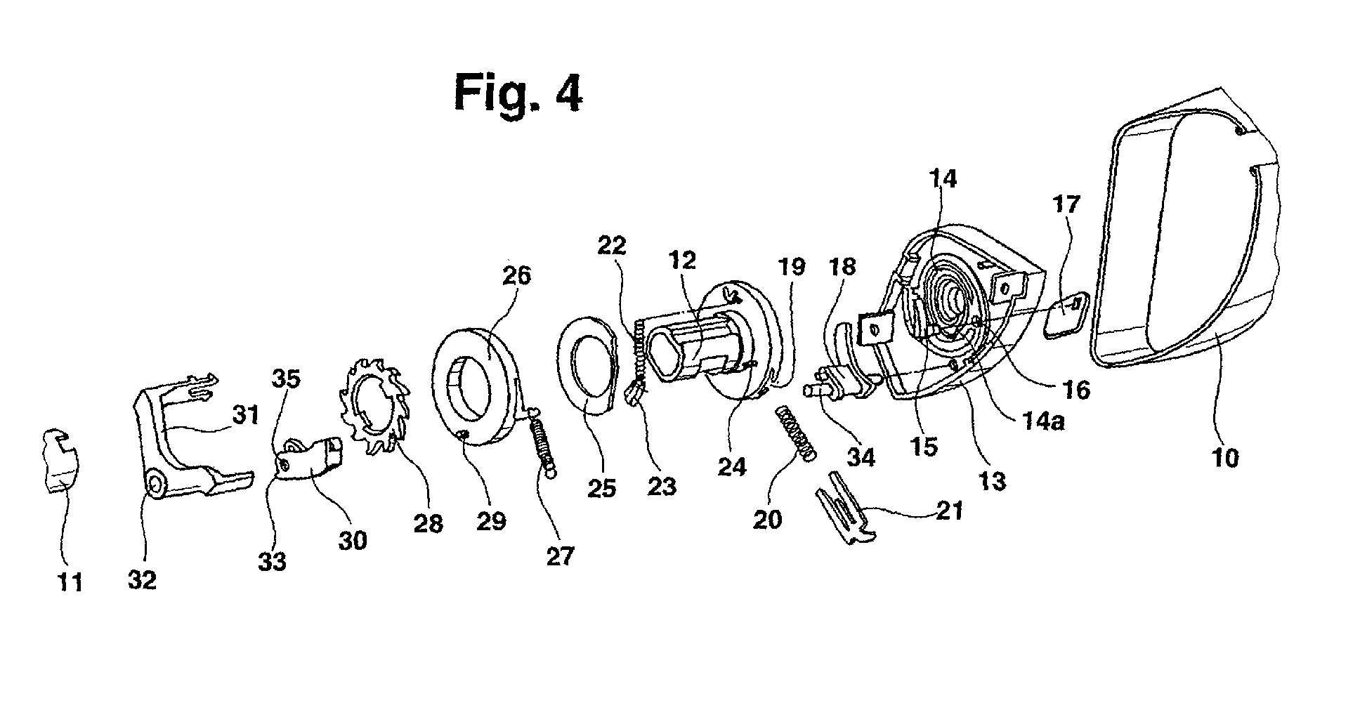
- the hub 12 also has an annular flange with a radial guide 19 is provided for a radially movable link finger 21.
- the backdrop finger 21 is associated with a compression spring 20 which is located on the inside in the guide receptacle 19 and is supported on the outside on the link finger 21, so that the Link finger 21 is spring-loaded in its functional position radially outwards.
- the hub 12 is including its ring flange in one with the Cassette hollow profile fixed spiral housing 13 stored.
- the spiral casing 13 is on the side facing the ring flange with a coaxial around the Axis of rotation of the winding shaft and the hub 12 arranged spiral groove 14, the one with a fixed, but resilient, tongue-shaped switch 14a and with a pivotable adjusting switch 15 in the area of a radial further outer turn is provided.
- the switch 15 is in one corresponding passage 16 of the volute 13 is pivotally mounted, the corresponding journal of the switch 15 has a square end has to the opposite side from the wall of the volute 13 emerges (Fig. 4 and 8).
- This square end is rotatably one Set weight 17 placed, the center of gravity so eccentric to the bearing axis the switch 15 is positioned that depending on the position of the backrest 4 a gravity-dependent pivoting of the actuating weight 17 and consequently an adjustment of the control switch 15 also takes place.
- Shift lever 18 pivotally mounted, which is an arcuate curve guide element has that towards its free end - clockwise of the spiral groove 14 seen in FIG. 4 - the radially outermost turn of the spiral groove 14 overlaid.
- the shift lever 18 is parallel to a bearing pin 34 Switch 15 in the spiral housing 13 pivotally mounted.
- the opposite The end of the bearing pin 34 is in a bearing bush 32 of a bearing bracket 31 pivotally mounted, the entire functional parts axially engages and via corresponding, not specified locking webs firmly in the Spiral housing 13 is anchored.
- an inertia disc 25 is also rotatably mounted a blocking element 23 is assigned, which on a pin 24 which is axially from projects from the annular flange of the hub 12, is pivotally mounted.
- the blocking element 23 is assigned a compression spring 22, which is on the one hand on the blocking element 23 and on the other hand at an unspecified stop (see dash-dotted line in Fig. 4) of the ring flange of the hub 12 supports.
- the Inertia disk 25 is designed asymmetrically by being straight on one side is separated.
- the blocking element 23 lies through in this edge region the compression spring 22 during normal operation of the control device.
- the blocking element 23 acts as a driver for the inertial disc 25 by transmitting the rotation of the hub 12 to the inertia disk 25.
- the tension spring 27 with a stop cam 37 of Spiral housing (Fig. 5 to 7 and 9) is connected.
- the locking cover 26 protruding inwards from the jacket area, evenly over the circumference Distributed locking teeth 27 (Fig. 9), when the blocking element is deflected 23 engages with the blocking element 23 through the inertia disk 25 devices.
- a ratchet disk 28 is provided axially adjacent to the latching cover 26, which is held on the hub 12 in a rotationally locking manner.
- Cams are provided on the inner periphery of the pawl disk 28, which in the axial grooves (not specified) of the hub 12 are inserted axially.
- the pawl disc 28 is assigned a pawl 30 which is designed in a bow shape and an inner flat leg associated with the pawl disk 28 and has an outer flat leg assigned to the bearing bracket 31.
- the Pawl 30 is attached to the shift lever 28 by being on the trunnion 34 by means of a bore 35 on the one hand and on a smaller one, parallel to Bearing pin 34 on the shift lever 18 positioned holding pin on the other hand with a another hole is plugged from the inner flat leg.
- the acceleration-sensitive blocking principle is based on the drawings described.
- the protective device rotates during normal operation the hub 12 with the winding shaft 11, whereas the locking cover 26, is rotatably supported on the hub 12 by the tension spring 27 on the fixed Spiral housing 13 is held in position.
- the link pin projecting into the link guide 36 of the pawl 30 29 so moved within the link guide 36 that the pawl 30 positioned in their unlocked state relative to the pawl disc 28 is.
- the blocking element 23 is free of play by means of the compression spring 22 Inertia disk 25.
- the inertia disk 25 lies above a defined pull-out acceleration, due to its mass, the inertia disk 25 remains in relation to the hub 12, which inevitably causes the blocking element 23 to continue with the hub 12 rotates, is directed radially outwards.
- the blocking element 23 comes in Engagement with one of the locking teeth 38 on the inner circumference of the jacket of the locking cover 26, the blocking element 23 being adjacent to the one that is currently adjacent Locking tooth 38 wedged.
- the locking cover 26 is taken along. about the locking pin 29 on the locking cover 26 is inevitably deflected the pawl 30, by entering into the locking teeth of the pawl disk 28.
- the pawl 30 strikes the locking toothing of the pawl disk 28 wedges the entire mechanism, whereby the winding shaft 11 blocks becomes.
- the switch 15 by the control weight 17th due to the upright functional position of the backrest 4 inevitably in a an outer, adjacent winding path blocking, deflected position pivoted (Fig. 6).
- the driver finger 21 In the rest position completely rolled up on the winding shaft 1 of the separation network 6 is the driver finger 21 in the area of innermost spiral turn of the spiral groove 14 and is opposed by the compression spring 20 pressed the wall of this spiral turn.
- the sliding finger 21 moves clockwise - on the 5 and 6 related - in the turns of the spiral groove 14th along.
- the control switch 15 is in its closed position by the control weight 17 Setting position.
- driver finger jumps on this switch 14a directly to the next inner spiral turn around, so that a spiral turn is saved compared to the pull-out has been.
- the driver finger runs until the separating network 6 is completely rolled up 21 thus completely around again in the innermost spiral turn, jumps to the next higher turn, then the outstanding turn to end again at the inner end of the inner spiral turn.
- the actuating weight is 17th pivoted by its own weight so that the switch 15 in its open Position is positioned in which an outer spiral turn is blocked and the Driver finger is forced back to the next inner spiral turn.
- the driver finger when pulling out the separation network 6 can not in the Run in the outermost spiral turn and actuate the shift lever 18 so that the Isolation network 6 can be extended to its end without limitation.
- the reclining position of the backrest 4 according to FIG. 7 is analogous to the rolling-up process with the functional position of the backrest 4 with the difference that the driver finger 21 in the area of the innermost spiral turn jumps to the next outer spiral turn several times until the separation net 6 is completely rolled up.
- the design of the spiral groove 14 and thus of the spiral housing 13 is for the different determining the separation network extension lengths to be realized.
- the total length of the separation network 6 is structurally predetermined.
- the stretched length of the innermost spiral turn defines the possible Length variations. Are the corresponding tolerances and separation network length variants is within this length range of the innermost spiral turn Use of one and the same spiral housing 13 for these different Separation network lengths possible.
- At least one support extension 33 is provided, which at a Locking in a corresponding profile recess of the cassette hollow profile 8 9 can wedge.
- the power flow thus overflows from the separation network the winding shaft 11 to the pawl disk 28, from there to the pawl 30 and then into the cassette hollow profile 8, which provides a particularly stable support and thus blocking or blocking can be achieved. This is an advantage if the forces are so great that only the pawl and the pawl disc cannot ensure a secure locking of the winding shaft.
- a protective device 3a according to the invention 10 and 11 is the control device except for those described below Designed differences according to the previously described embodiment, all in particular except for the differences described below 4 recognizable parts of the protective device are present.
- the difference in the protective device shown in FIGS. 10 and 11 is that as a sensor device for detecting the functional position of the as a winding housing serving cassette housing the switching element 15 actuating switching element is formed by a sensor pin 17a which pivots the switch and in the manner of a button from the winding housing according to FIGS. 10 and 11 protrudes. As soon as the winding housing at a stop 39 in the relevant functional position is brought, the sensor pin 17a comes to the stop 39 to the system and is pressed into the winding housing inwards.
- a winding case the protective device 3b is positioned in the region of a backrest 4b, the winding housing either in body-side brackets or is securely secured in the backrest brackets.
- the tarpaulin 6b is Extendable into two different protective positions, which are due to the in the side walls provided receptacles 5b on the vehicle are defined.
- the control device and the switching device essentially correspond to those previously with reference to Figures 10 and 11 and otherwise those disclosed by FIGS.
- the tarpaulin 6b at its front end a contour part on the side with hooks 7b is provided in an extension of a pull-out strip of the dimensionally stable contour part.
Landscapes
- Engineering & Computer Science (AREA)
- Mechanical Engineering (AREA)
- Transportation (AREA)
- Vehicle Step Arrangements And Article Storage (AREA)
- Seats For Vehicles (AREA)
- Fittings On The Vehicle Exterior For Carrying Loads, And Devices For Holding Or Mounting Articles (AREA)
- Chairs For Special Purposes, Such As Reclining Chairs (AREA)
- Measurement Of The Respiration, Hearing Ability, Form, And Blood Characteristics Of Living Organisms (AREA)
Abstract
Description
- Fig. 1
- zeigt schematisch in einer Seitenansicht einen KombiPersonenkraftwagen mit einer Ausführungsform einer erfindungsgemäßen Schutzvorrichtung, wobei sich das flexible Flächengebilde der Schutzvorrichtung bei aufrechter Funktionsposition der Rückenlehne in seiner vertikalen Schutzposition befindet,
- Fig. 2
- den Kombi-Personenkraftwagen nach Fig. 1 mit umgeklappter Rückenlehne, wobei sich das flexible Flächengebilde in seiner vorderen, vertikalen Schutzposition befindet,
- Fig. 3
- in vergrößerter, perspektivischer Darstellung die Schutzvorrichtung nach den Fig. 1 und 2 mit teilweise ausgezogenem Flächengebilde in Form eines Trennnetzes,
- Fig. 4
- in einer Explosionsdarstellung die verschiedenen Einzelteile der auf die Wickelwelle einwirkenden Steuereinrichtung,
- Fig. 5
- in weiterer Explosionsdarstellung eine Funktionsgruppe der Schutzvorrichtung nach den Fig. 1 bis 4,
- Fig. 6
- in perspektivischer Explosionsdarstellung die Funktionsgruppe nach Fig. 5 unter Weglassung eines weiteren Einzelteiles,
- Fig. 7
- in perspektivischer Explosionsdarstellung eine weitere Funktionsgruppe der Schutzvorrichtung in umgeklappter Liegeposition der Rückenlehne,
- Fig. 8
- eine außenseitige Ansicht eines Funktionsteiles der Schutzvorrichtung,
- Fig. 9
- eine Draufsicht auf die Steuereinrichtung nach den vorhergehenden Figuren in einer mit einem Tragprofil des Kassettengehäuses verkeilten Sperrposition,
- Fig. 10
- in perspektivischer Darstellung eine weitere Ausführungsform einer erfindungsgemäßen Schutzvorrichtung im Fahrzeuginnenraum eines Kraftfahrzeugs,
- Fig. 11
- in vergrößerter, perspektivischer Darstellung einen Ausschnitt der Schutzvorrichtung nach Fig. 10,
- Fig. 12
- in schematischer, perspektivischer Darstellung eine weitere Ausführungsform einer erfindungsgemäßen Schutzvorrichtung mit horizontal ausziehbarem Flächengebilde und
- Fig. 13
- in vergrößerter Darstellung ein Funktionsteil der Schutzvorrichtung nach Fig. 12.
Claims (10)
- Schutzvorrichtung zur Sicherung eines Laderaumes in einem Fahrzeuginnenraum mit einer in einem Wickelgehäuse drehbar gelagerten Wickelwelle, auf der ein flexibles Flächengebilde ausziehbar und aufrollbar gehalten ist, das in wenigstens eine kurze und wenigstens eine lange Schutzposition ausziehbar und fahrzeugfest verankerbar ist, dadurch gekennzeichnet, dass eine Schalteinrichtung (17, 17a, 17b) zum Auswählen einer der jeweiligen Schutzposition entsprechenden Sollposition des Flächengebildes sowie eine Steuereinrichtung vorgesehen sind, wobei die Steuereinrichtung die Umdrehungen der Wickelwelle (11) erfasst und abhängig von der ausgewählten Sollposition den Auszugweg für das Flächengebilde (6) auf eine entsprechende Länge begrenzt oder für einen vollständigen Auszug freigibt.
- Schutzvorrichtung nach Anspruch 1, wobei das Wickelgehäuse in wenigstens zwei bezüglich ihrer Fahrzeuginnenraumhöhe unterschiedlichen Funktionslagen fahrzeugfest positionierbar ist und wobei das Flächengebilde in beiden Funktionslagen des Wickelgehäuse in wenigstens eine vertikale Schutzposition ausziehbar und fahrzeugfest verankerbar ist, dadurch gekennzeichnet, dass die Steuereinrichtung eine Sensoreinrichtung zur Erfassung der Funktionslage des Wickelgehäuses aufweist, die mit der Schalteinrichtung zum Freigeben oder Begrenzen des Auszugweges des Flächengebildes verbunden ist.
- Schutzvorrichtung nach Anspruch 1, dadurch gekennzeichnet, dass die Steuereinrichtung eine mechanische Sperrvorrichtung (15, 17, 18, 28, 30) aufweist, die für ein Blockieren der Wickelwelle (11) vorgesehen ist.
- Schutzvorrichtung nach Anspruch 3, wobei das Wickelgehäuse an einer klappbaren Rückenlehne angeordnet ist, dadurch gekennzeichnet, dass als Schalteinrichtung ein schwerkraftabhängig schaltbares Stellelement (15, 17) vorgesehen ist, das derart beweglich angeordnet ist, dass es durch die Bewegung der Rückenlehne in ihre Funktions- oder Liegeposition in unterschiedliche Endpositionen überführbar ist.
- Schutzvorrichtung nach Anspruch 1, dadurch gekennzeichnet, dass die Steuereinrichtung eine gehäusefeste oder wickelwellenseitige Kulissenspirale (14) und einen entsprechend entgegengesetzt wickelwellenseitigen oder gehäusefesten, in die Kulissenspirale (14) eingreifenden und radial beweglichen Kulissenfinger (21) aufweist, und dass das Stellelement mit einer in der Kulissenspirale (14) beweglich positionierten Stellweiche (15) versehen ist.
- Schutzvorrichtung nach Anspruch 1, dadurch gekennzeichnet, dass der Wickelwelle (11) eine beschleunigungsabhängig betätigte Blockiervorrichtung (23, 25, 26, 28, 30, 38) zugeordnet ist, die unabhängig von der Sperrvorrichtung bei einem einen definierten Grenzwert überschreitenden Beschleunigungswert die Wickelwelle (11) arretiert.
- Schutzvorrichtung nach Anspruch 6, dadurch gekennzeichnet, dass die Blockiervorrichtung ein Trägheitselement (25) aufweist.
- Schutzvorrichtung nach Anspruch 6, dadurch gekennzeichnet, dass die Sperrvorrichtung und/oder die Blockiervorrichtung derart gestaltet sind, dass bei einer Blockade der Wickelwelle (11) zusätzlich eine formschlüssige Verkeilung mit einem Tragprofil (8) des Kassettengehäuses erfolgt.
- Schutzvorrichtung nach Anspruch 6, dadurch gekennzeichnet, dass die Sperrvorrichtung oder die Blockiervorrichtung eine Sperrklinke (30) sowie eine drehschlüssig mit der Wickelwelle (11) verbundene Sperrklinkenscheibe (28) aufweisen, wobei die Sperrklinke (30) durch den Kulissenfinger (21) oder das Trägheitselement (25) direkt oder indirekt ansteuerbar ist.
- Schutzvorrichtung nach Anspruch 9, dadurch gekennzeichnet, dass die Steuereinrichtung derart gestaltet ist, dass die Sperrklinke (30) aktiv in eine Zahnlücke der Sperrklinkenscheibe (28) eingesteuert wird.
Applications Claiming Priority (2)
| Application Number | Priority Date | Filing Date | Title |
|---|---|---|---|
| DE10044958 | 2000-09-12 | ||
| DE10044958A DE10044958C2 (de) | 2000-09-12 | 2000-09-12 | Schutzvorrichtung zur Sicherung eines Laderaumes in einem Fahrzeuginnenraum |
Publications (3)
| Publication Number | Publication Date |
|---|---|
| EP1186480A2 true EP1186480A2 (de) | 2002-03-13 |
| EP1186480A3 EP1186480A3 (de) | 2003-11-19 |
| EP1186480B1 EP1186480B1 (de) | 2008-04-30 |
Family
ID=7655863
Family Applications (1)
| Application Number | Title | Priority Date | Filing Date |
|---|---|---|---|
| EP01119385A Expired - Lifetime EP1186480B1 (de) | 2000-09-12 | 2001-08-11 | Schutzvorrichtung zur Sicherung eines Laderaumes in einem Fahrzeuginnenraum |
Country Status (6)
| Country | Link |
|---|---|
| US (1) | US6598921B2 (de) |
| EP (1) | EP1186480B1 (de) |
| JP (1) | JP2002127827A (de) |
| KR (1) | KR20020021017A (de) |
| CN (1) | CN1343592A (de) |
| DE (3) | DE10044958C2 (de) |
Families Citing this family (35)
| Publication number | Priority date | Publication date | Assignee | Title |
|---|---|---|---|---|
| DE59709928D1 (de) * | 1996-12-06 | 2003-05-28 | Bos Gmbh | Sicherheitsnetzanordnung mit vereinfachter bedienung |
| DE10242510B4 (de) * | 2002-09-12 | 2005-12-08 | Bos Gmbh & Co. Kg | Kfz-Sicherheitseinrichtung, insbesondere Trennnetz |
| US6739812B1 (en) * | 2002-12-05 | 2004-05-25 | Daimlerchrysler Corporation | Rear cargo barrier system |
| US6962382B2 (en) * | 2003-05-23 | 2005-11-08 | David Scarlett | Barrier system |
| US7118152B2 (en) * | 2004-05-07 | 2006-10-10 | Ford Global Technologies, Llc | Automotive cargo restraint and security screen |
| DE102005043768B3 (de) * | 2005-09-13 | 2007-03-01 | Dr.Ing.H.C. F. Porsche Ag | Schutzeinrichtung für Fahrzeuginsassen |
| EP1787864B1 (de) * | 2005-11-22 | 2009-03-25 | Mazda Motor Corporation | Hintere Struktur eines Kraftfahrzeugs |
| US7287796B2 (en) * | 2006-02-22 | 2007-10-30 | Ford Global Technologies, Llc | Integrated cargo net for a vehicle |
| DE102006034635A1 (de) * | 2006-07-27 | 2008-01-31 | Dr.Ing.H.C. F. Porsche Ag | Schutzvorrichtung für einen Laderaum |
| US7931177B2 (en) * | 2007-08-14 | 2011-04-26 | Bos Gmbh & Co. Kg | Storage container for use in a boot |
| DE102007045037A1 (de) * | 2007-09-13 | 2009-04-02 | Bos Gmbh & Co. Kg | Vorrichtung zum Verstauen von Gegenständen in einem Kraftfahrzeug |
| DE102007058255B3 (de) * | 2007-11-26 | 2009-07-02 | Bos Gmbh & Co. Kg | Staufach mit Tragrahmen und Aufnahmevorrichtung für einen Tragrahmen |
| DE102009038066B3 (de) * | 2009-08-19 | 2010-11-18 | Hs Genion Gmbh Engineering Services | Sicherheitseinrichtung für einen Laderaum eines Kraftfahrzeugs |
| DE102009048513B4 (de) * | 2009-10-07 | 2011-06-22 | HS Genion GmbH Engineering Services, 82205 | Laderaumabtrennung |
| TW201114629A (en) * | 2009-10-28 | 2011-05-01 | Macauto Ind Co Ltd | Vehicle safety protection device |
| DE102009051283B3 (de) * | 2009-10-29 | 2010-12-09 | Hs Genion Gmbh Engineering Services | Laderaumtrennung mit Auszugsbegrenzungseinrichtung |
| US8136859B2 (en) * | 2009-12-29 | 2012-03-20 | Kawasaki Jukogyo Kabushiki Kaisha | Pick-up style utility vehicle with expandable cargo bed |
| US8128144B2 (en) * | 2009-12-30 | 2012-03-06 | Kawasaki Jukogyo Kabushiki Kaisha | Pick-up style utility vehicle with expandable cargo bed |
| CN102781726B (zh) * | 2011-03-02 | 2014-11-19 | 丰田自动车株式会社 | 对于上边梁的部件设置结构 |
| US9121208B2 (en) * | 2012-03-05 | 2015-09-01 | Kanybek Dosbolovich Nur-tegin | Unclimbable child barrier |
| US9511734B2 (en) * | 2015-01-29 | 2016-12-06 | Ford Global Technologies, Llc | Passenger protection system |
| DE102015206661B4 (de) * | 2015-04-14 | 2022-02-24 | Bos Gmbh & Co. Kg | Schutzvorrichtung für ein Kraftfahrzeug |
| US9975491B2 (en) | 2015-10-19 | 2018-05-22 | Ford Global Technologies Llc | Retractable cargo cover system |
| DE102016116775C5 (de) * | 2016-09-07 | 2023-07-13 | Macauto Industrial Co., Ltd. | Laderaumtrennnetz mit Auszugsbegrenzung |
| US10343574B2 (en) | 2017-01-17 | 2019-07-09 | Ford Global Technologies, Llc | Glove box door assembly |
| US10576869B2 (en) | 2017-01-26 | 2020-03-03 | Ford Global Technologies, Llc | Self-retractable cargo net |
| DE102017208879B4 (de) | 2017-05-24 | 2021-09-09 | Bos Gmbh & Co. Kg | Schutzvorrichtung für den Laderaum eines Kraftfahrzeugs |
| US10611314B2 (en) * | 2017-09-29 | 2020-04-07 | Faurecia Automotive Seating, Llc | Vehicle privacy screen |
| DE202018103592U1 (de) * | 2018-06-25 | 2018-07-09 | Westdeutscher Drahtseil-Verkauf Dolezych Gmbh & Co. Kg | Flächiges Sicherungsmittel |
| CN111376863A (zh) * | 2018-12-28 | 2020-07-07 | 周承岗 | 张拉整体结构碰撞安全系统 |
| US11286048B2 (en) * | 2019-02-11 | 2022-03-29 | The Boeing Company | Aircraft cargo restraint system and method for restraining cargo within an aircraft |
| EP3838659B1 (de) * | 2019-12-19 | 2022-08-24 | Ningbo Geely Automobile Research & Development Co. Ltd. | Lastenteiler zur anordnung zwischen einer ersten fahrzeugsitzrückenlehne und einer benachbarten zweiten fahrzeugsitzrückenlehne und einem fahrzeugsitz |
| CN113104137B (zh) * | 2021-04-22 | 2022-11-29 | 广东雅迪机车有限公司 | 一种稳定行驶避免前倾翻车的电动车 |
| JP7720774B2 (ja) * | 2021-12-17 | 2025-08-08 | 日本発條株式会社 | 車両用シート |
| CN115583217B (zh) * | 2022-11-25 | 2023-03-14 | 福建中青汽车技术有限公司 | 一种安装便捷的驾驶防干扰装置 |
Citations (1)
| Publication number | Priority date | Publication date | Assignee | Title |
|---|---|---|---|---|
| DE19643691C2 (de) | 1996-10-23 | 2000-03-23 | Baumeister & Ostler Gmbh Co | Sicherheitsnetzanordnung |
Family Cites Families (11)
| Publication number | Priority date | Publication date | Assignee | Title |
|---|---|---|---|---|
| DE2739741A1 (de) * | 1977-09-03 | 1979-03-15 | Daimler Benz Ag | Mit einer einen laderaum verschliessenden hecktuere versehener kraftwagen |
| US5288122A (en) * | 1990-02-16 | 1994-02-22 | Ab Volvo | Load restraining device |
| DE4336380C2 (de) * | 1993-10-25 | 1995-08-10 | Baumeister & Ostler Gmbh Co | Sicherheitsnetzanordnung |
| JPH1024790A (ja) * | 1996-07-11 | 1998-01-27 | Ashimori Ind Co Ltd | 車両用巻取式荷崩れ防止装置 |
| DE59709928D1 (de) * | 1996-12-06 | 2003-05-28 | Bos Gmbh | Sicherheitsnetzanordnung mit vereinfachter bedienung |
| DE19650768C2 (de) * | 1996-12-06 | 2001-08-16 | Baumeister & Ostler Gmbh Co | Sicherheitsnetzanordnung mit vereinfachter Bedienung |
| GB2321436B (en) * | 1997-01-24 | 2000-12-20 | Autoliv Dev | Improvements in or relating to a safety device in a motor vehicle |
| DE19708192C5 (de) * | 1997-02-28 | 2006-08-03 | Bos Gmbh & Co. Kg | Laderaum-Trennvorrichtung für Kraftwagen, insbesondere für Kombinations-Personenkraftwagen |
| US5882084A (en) * | 1997-10-24 | 1999-03-16 | Trw Vehicle Safety Systems Inc. | Tilt locking seat belt retractor |
| EP0970850B1 (de) * | 1998-01-05 | 2007-10-17 | Ashimori Kogyo Kabushiki Kaisha | Einziehbares unterteilungssystem für fahrzeuge |
| DE19946382A1 (de) * | 1999-09-28 | 2001-04-12 | Baumeister & Ostler Gmbh Co | Laderaumabtrennung für Kraftfahrzeuge |
-
2000
- 2000-09-12 DE DE10044958A patent/DE10044958C2/de not_active Expired - Fee Related
- 2000-12-14 DE DE20021559U patent/DE20021559U1/de not_active Expired - Lifetime
-
2001
- 2001-08-11 EP EP01119385A patent/EP1186480B1/de not_active Expired - Lifetime
- 2001-08-11 DE DE50113905T patent/DE50113905D1/de not_active Expired - Lifetime
- 2001-09-10 KR KR1020010055487A patent/KR20020021017A/ko not_active Withdrawn
- 2001-09-11 JP JP2001275085A patent/JP2002127827A/ja active Pending
- 2001-09-12 CN CN01132986A patent/CN1343592A/zh active Pending
- 2001-09-12 US US09/949,769 patent/US6598921B2/en not_active Expired - Fee Related
Patent Citations (1)
| Publication number | Priority date | Publication date | Assignee | Title |
|---|---|---|---|---|
| DE19643691C2 (de) | 1996-10-23 | 2000-03-23 | Baumeister & Ostler Gmbh Co | Sicherheitsnetzanordnung |
Also Published As
| Publication number | Publication date |
|---|---|
| KR20020021017A (ko) | 2002-03-18 |
| DE20021559U1 (de) | 2001-03-29 |
| EP1186480A3 (de) | 2003-11-19 |
| DE50113905D1 (de) | 2008-06-12 |
| US6598921B2 (en) | 2003-07-29 |
| EP1186480B1 (de) | 2008-04-30 |
| DE10044958A1 (de) | 2002-04-18 |
| CN1343592A (zh) | 2002-04-10 |
| US20020067047A1 (en) | 2002-06-06 |
| DE10044958C2 (de) | 2003-04-10 |
| JP2002127827A (ja) | 2002-05-09 |
Similar Documents
| Publication | Publication Date | Title |
|---|---|---|
| EP1186480A2 (de) | Schutzvorrichtung zur Sicherung eines Laderaumes in einem Fahrzeuginnenraum | |
| EP0771690B1 (de) | Sitz für Fahrzeuge | |
| DE60006758T2 (de) | Kraftfahrzeuglenkungsdiebstahlsicherung | |
| EP1060956B1 (de) | Trenneinrichtung mit variabler Rückzugskraft | |
| EP1447275B1 (de) | Kraftfahrzeug mit einer Schutzvorrichtung für einen Laderaum des Kraftfahrzeuges | |
| EP0754594B1 (de) | Abdeckeinrichtung mit hoher Crashsicherheit | |
| DE19643691A1 (de) | Sicherheitsnetzanordnung | |
| EP1844984A2 (de) | Laderaum für ein Kraftfahrzeug mit einer Schutzvorrichtung | |
| DE102007025327A1 (de) | Fahrzeugsitzanordnung | |
| EP0712757A1 (de) | Laderaumabdeckung für ein Kraftfahrzeug | |
| EP0916552B1 (de) | Ausfahrbarer Überrollbügel für Kraftfahrzeuge | |
| DE10027020B4 (de) | Mittelkonsole für Fahrzeuge | |
| EP1775165B1 (de) | Abdeckvorrichtung für einen Laderaum eines Kraftfahrzeugs | |
| DE29819293U1 (de) | Sicherheitseinrichtung für Fahrzeuge, insbesondere Laderaum-Trennvorrichtung für Kraftwagen, wie z.B. für Kombinations-Personenkraftwagen o.dgl. | |
| DE102005029253B4 (de) | Cabriolet mit einem Überrollschutzsystem | |
| DE102006028664B4 (de) | Überrollschutzsystem für ein Kraftfahrzeug | |
| EP1741600B1 (de) | Laderaumschutzvorrichtung für ein Kraftfahrzeug | |
| EP1285827B1 (de) | Gurtaufroller für einen Fahrzeugsicherheitsgurt | |
| DE102016116775C5 (de) | Laderaumtrennnetz mit Auszugsbegrenzung | |
| EP0861758B1 (de) | Laderaum-Trennvorrichtung für Kraftwagen, insbesondere für Kombinations-Personenkraftwagen | |
| DE19532276C2 (de) | Laderaumabdeckung für einen Kombi-Personenkraftwagen | |
| DE19527068C2 (de) | Hohlprofil für eine Laderaumsicherung | |
| EP1808342A2 (de) | Schutzvorrichtung für ein Kraftfahrzeug | |
| EP1736371A1 (de) | Kraftfahrzeug mit einem Überrollschutzsystem | |
| DE102006008873A1 (de) | Schutzvorrichtung für einen Laderaum eines Kraftfahrzeugs |
Legal Events
| Date | Code | Title | Description |
|---|---|---|---|
| PUAI | Public reference made under article 153(3) epc to a published international application that has entered the european phase |
Free format text: ORIGINAL CODE: 0009012 |
|
| AK | Designated contracting states |
Kind code of ref document: A2 Designated state(s): AT BE CH CY DE DK ES FI FR GB GR IE IT LI LU MC NL PT SE TR |
|
| AX | Request for extension of the european patent |
Free format text: AL;LT;LV;MK;RO;SI |
|
| PUAL | Search report despatched |
Free format text: ORIGINAL CODE: 0009013 |
|
| AK | Designated contracting states |
Kind code of ref document: A3 Designated state(s): AT BE CH CY DE DK ES FI FR GB GR IE IT LI LU MC NL PT SE TR |
|
| AX | Request for extension of the european patent |
Extension state: AL LT LV MK RO SI |
|
| 17P | Request for examination filed |
Effective date: 20040326 |
|
| AKX | Designation fees paid |
Designated state(s): DE FR GB SE |
|
| GRAP | Despatch of communication of intention to grant a patent |
Free format text: ORIGINAL CODE: EPIDOSNIGR1 |
|
| GRAS | Grant fee paid |
Free format text: ORIGINAL CODE: EPIDOSNIGR3 |
|
| GRAA | (expected) grant |
Free format text: ORIGINAL CODE: 0009210 |
|
| AK | Designated contracting states |
Kind code of ref document: B1 Designated state(s): DE FR GB SE |
|
| REG | Reference to a national code |
Ref country code: GB Ref legal event code: FG4D Free format text: NOT ENGLISH |
|
| REF | Corresponds to: |
Ref document number: 50113905 Country of ref document: DE Date of ref document: 20080612 Kind code of ref document: P |
|
| REG | Reference to a national code |
Ref country code: SE Ref legal event code: TRGR |
|
| PGFP | Annual fee paid to national office [announced via postgrant information from national office to epo] |
Ref country code: FR Payment date: 20080818 Year of fee payment: 8 |
|
| PGFP | Annual fee paid to national office [announced via postgrant information from national office to epo] |
Ref country code: GB Payment date: 20080822 Year of fee payment: 8 |
|
| ET | Fr: translation filed | ||
| PGFP | Annual fee paid to national office [announced via postgrant information from national office to epo] |
Ref country code: SE Payment date: 20080825 Year of fee payment: 8 |
|
| PLBE | No opposition filed within time limit |
Free format text: ORIGINAL CODE: 0009261 |
|
| STAA | Information on the status of an ep patent application or granted ep patent |
Free format text: STATUS: NO OPPOSITION FILED WITHIN TIME LIMIT |
|
| 26N | No opposition filed |
Effective date: 20090202 |
|
| GBPC | Gb: european patent ceased through non-payment of renewal fee |
Effective date: 20090811 |
|
| REG | Reference to a national code |
Ref country code: FR Ref legal event code: ST Effective date: 20100430 |
|
| PG25 | Lapsed in a contracting state [announced via postgrant information from national office to epo] |
Ref country code: FR Free format text: LAPSE BECAUSE OF NON-PAYMENT OF DUE FEES Effective date: 20090831 |
|
| PG25 | Lapsed in a contracting state [announced via postgrant information from national office to epo] |
Ref country code: GB Free format text: LAPSE BECAUSE OF NON-PAYMENT OF DUE FEES Effective date: 20090811 |
|
| PG25 | Lapsed in a contracting state [announced via postgrant information from national office to epo] |
Ref country code: SE Free format text: LAPSE BECAUSE OF NON-PAYMENT OF DUE FEES Effective date: 20090812 |
|
| PGFP | Annual fee paid to national office [announced via postgrant information from national office to epo] |
Ref country code: DE Payment date: 20120828 Year of fee payment: 12 |
|
| PG25 | Lapsed in a contracting state [announced via postgrant information from national office to epo] |
Ref country code: DE Free format text: LAPSE BECAUSE OF NON-PAYMENT OF DUE FEES Effective date: 20140301 |
|
| REG | Reference to a national code |
Ref country code: DE Ref legal event code: R119 Ref document number: 50113905 Country of ref document: DE Effective date: 20140301 |