EP1185214B1 - Expandable medical device delivery system - Google Patents
Expandable medical device delivery system Download PDFInfo
- Publication number
- EP1185214B1 EP1185214B1 EP00930734A EP00930734A EP1185214B1 EP 1185214 B1 EP1185214 B1 EP 1185214B1 EP 00930734 A EP00930734 A EP 00930734A EP 00930734 A EP00930734 A EP 00930734A EP 1185214 B1 EP1185214 B1 EP 1185214B1
- Authority
- EP
- European Patent Office
- Prior art keywords
- supporting device
- tissue supporting
- guide member
- guide
- balloon
- Prior art date
- Legal status (The legal status is an assumption and is not a legal conclusion. Google has not performed a legal analysis and makes no representation as to the accuracy of the status listed.)
- Expired - Lifetime
Links
Images


Classifications
-
- A—HUMAN NECESSITIES
- A61—MEDICAL OR VETERINARY SCIENCE; HYGIENE
- A61F—FILTERS IMPLANTABLE INTO BLOOD VESSELS; PROSTHESES; DEVICES PROVIDING PATENCY TO, OR PREVENTING COLLAPSING OF, TUBULAR STRUCTURES OF THE BODY, e.g. STENTS; ORTHOPAEDIC, NURSING OR CONTRACEPTIVE DEVICES; FOMENTATION; TREATMENT OR PROTECTION OF EYES OR EARS; BANDAGES, DRESSINGS OR ABSORBENT PADS; FIRST-AID KITS
- A61F2/00—Filters implantable into blood vessels; Prostheses, i.e. artificial substitutes or replacements for parts of the body; Appliances for connecting them with the body; Devices providing patency to, or preventing collapsing of, tubular structures of the body, e.g. stents
- A61F2/95—Instruments specially adapted for placement or removal of stents or stent-grafts
- A61F2/954—Instruments specially adapted for placement or removal of stents or stent-grafts for placing stents or stent-grafts in a bifurcation
-
- A—HUMAN NECESSITIES
- A61—MEDICAL OR VETERINARY SCIENCE; HYGIENE
- A61F—FILTERS IMPLANTABLE INTO BLOOD VESSELS; PROSTHESES; DEVICES PROVIDING PATENCY TO, OR PREVENTING COLLAPSING OF, TUBULAR STRUCTURES OF THE BODY, e.g. STENTS; ORTHOPAEDIC, NURSING OR CONTRACEPTIVE DEVICES; FOMENTATION; TREATMENT OR PROTECTION OF EYES OR EARS; BANDAGES, DRESSINGS OR ABSORBENT PADS; FIRST-AID KITS
- A61F2/00—Filters implantable into blood vessels; Prostheses, i.e. artificial substitutes or replacements for parts of the body; Appliances for connecting them with the body; Devices providing patency to, or preventing collapsing of, tubular structures of the body, e.g. stents
- A61F2/95—Instruments specially adapted for placement or removal of stents or stent-grafts
- A61F2/958—Inflatable balloons for placing stents or stent-grafts
-
- A—HUMAN NECESSITIES
- A61—MEDICAL OR VETERINARY SCIENCE; HYGIENE
- A61F—FILTERS IMPLANTABLE INTO BLOOD VESSELS; PROSTHESES; DEVICES PROVIDING PATENCY TO, OR PREVENTING COLLAPSING OF, TUBULAR STRUCTURES OF THE BODY, e.g. STENTS; ORTHOPAEDIC, NURSING OR CONTRACEPTIVE DEVICES; FOMENTATION; TREATMENT OR PROTECTION OF EYES OR EARS; BANDAGES, DRESSINGS OR ABSORBENT PADS; FIRST-AID KITS
- A61F2/00—Filters implantable into blood vessels; Prostheses, i.e. artificial substitutes or replacements for parts of the body; Appliances for connecting them with the body; Devices providing patency to, or preventing collapsing of, tubular structures of the body, e.g. stents
- A61F2/82—Devices providing patency to, or preventing collapsing of, tubular structures of the body, e.g. stents
- A61F2/856—Single tubular stent with a side portal passage
-
- A—HUMAN NECESSITIES
- A61—MEDICAL OR VETERINARY SCIENCE; HYGIENE
- A61M—DEVICES FOR INTRODUCING MEDIA INTO, OR ONTO, THE BODY; DEVICES FOR TRANSDUCING BODY MEDIA OR FOR TAKING MEDIA FROM THE BODY; DEVICES FOR PRODUCING OR ENDING SLEEP OR STUPOR
- A61M25/00—Catheters; Hollow probes
- A61M25/10—Balloon catheters
- A61M2025/1043—Balloon catheters with special features or adapted for special applications
- A61M2025/1056—Balloon catheters with special features or adapted for special applications having guide wire lumens outside the main shaft, i.e. the guide wire lumen is within or on the surface of the balloon
Definitions
- the present invention relates to a delivery system for delivering tissue supporting medical devices, and more particularly to a system for implanting expandable, non-removable devices at the junction of two or more bodily lumens in a living animal or human to support the organs and maintain patency.
- the area to be supported by such devices is located at or near the junction of two or more lumens, called a bifurcation.
- a bifurcation In coronary angioplasty procedures, for example, it has been estimated that 15% to 20% of cases involve reinforcing the area at the junction of two arteries.
- Conventional stent implantation at such a junction results in at least partial blockage of the branch artery, affecting blood flow and impeding access to the branch artery for further angioplasty procedures.
- Known techniques for treating bifurcations generally deliver a mesh tissue supporting device into the artery and position the device over the bifurcation. According to the known methods, a surgeon then attempts to create one or more branch lumen access holes by inserting a balloon through the sidewall of the mesh device, and then inflating the balloon to simply push the local features of the mesh aside.
- These techniques are inherently random in nature: the exact point of expansion in the device lattice cannot be predicted, and the device may or may not expand satisfactorily at that point.
- Tissue support provided by these known techniques for treating bifurcated arteries is similarly unpredictable. In addition, the effectiveness of such procedures is limited because many mesh devices are unable to accommodate such expansion at random locations in the device structure. Further, prior art tissue supporting device delivery systems are unable to accurately position specific device features over the branch artery opening.
- tissue supporting devices also provide a low ratio of tissue coverage (metal-to-tissue area ratio) in the junction area. Low metal coverage and the resulting tissue prolapse are associated with higher restenosis rates.
- a main stent having a substantially circular side opening and a flared stent having a flared end are used together to treat a bifurcating vessel in a two step process.
- the main stent is positioned using an inflatable balloon catheter in the interior of the main stent and a stabilizing catheter extending through the side opening of the stent.
- the stabilizing catheter is used to place the side opening in the main stent at the opening to the branch vessel.
- the main stent is then expanded and the flared stent is inserted through the side opening into the vessel bifurcation.
- a system according to the preamble of claim 1 is known from EP-A-0 897 700.
- the invention includes expandable tissue supporting devices for use at lumen junctions or bifurcations, and a delivery system for accurately locating, orienting, and implanting the tissue supporting devices at the lumen junction or bifurcation.
- a system as defined in claim 1 for delivery of a tissue supporting device to a bifurcated body lumen.
- the system includes a catheter with an inflatable balloon configured to deliver an expandable tissue supporting device to the lumen, a guide member received on a side of the balloon and connected to the catheter, and a branch lumen guidewire extending along an exterior of the balloon and longitudinally slidable in the guide member.
- a guide member for use in delivery of a tissue supporting device to a bifurcated body lumen in a desired longitudinal and radial position.
- the guide member includes a guide loop for receiving a guidewire, means for securing the guide loop to a catheter, and at least one tab extending from the guide loop for holding the guide loop in position in a side hole of a tissue supporting device to be delivered.
- a method of delivering of a tissue supporting device to a bifurcated body lumen includes the steps of:
- the invention involves a system for delivery of a tissue supporting device to a bifurcated artery such that, on expansion, the tissue supporting device provides side ports of a specific size and geometry to accommodate bifurcations in the artery.
- the delivery system is capable of accurately orienting these side ports both radially and longitudinally with respect to branch lumen openings of the artery.
- the delivery system achieves orientation by utilizing a guide member 10 which is positioned to extend from the side port feature of the tissue supporting device.
- the tissue support device is delivered to the artery on a balloon catheter which is used for expansion of the device.
- the guide member 10 is tracked along a side branch guidewire which extends into the branch lumen, ultimately orienting the side port of the tissue supporting device properly at the branch lumen opening. While the tissue supporting device having the side port is expanded, the guide member 10 holds the tissue supporting device in the proper position. After expansion, the guide member 10 drops out of the enlarged side port and is withdrawn with the balloon catheter assembly.
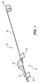
- FIG. 1 shows one embodiment of a guide member 10 in accordance with the present invention.
- the device 10 includes a main body 12 of which is preferably formed as a unitary piece comprising a loop 14, a spacer section 16, and two tabs 18.
- the inner diameter of the loop 14 is just large enough to provide clearance for a guidewire which will pass through the loop.
- the loop 14, spacer section 16, and tabs 18 may be integrally formed from a single piece of tubing.
- the radius of the tabs 18 conforms generally to the inner radius of the unexpanded tissue supporting device in which the guide loop will be mounted.
- the main body 12 of the guide member 10 is attached to a crimping lug 22 via a long, flexible tether 20.
- the tether 20 can be a simple wire attached to the main body 12 and crimping lug 22 at either end, or can be integrally formed from the same tube as the main body 12 and the crimping lug 22.
- the guide member 10 is preferably made radiopaque by one of several available methods.
- the wall thickness of the tube may be made thick enough for good radio opacity.
- the guide loop may be made from, plated, or coated with a radiopaque material. This is not objectionable since the guide member is withdrawn immediately after the procedure and does not become a permanent implant.
- the radiopaque guide member is crimped into the side port of the tissue supporting device as described in further detail below, the exact location of the side port will be clearly visible on the fluoroscope.
- a preferred tissue supporting device for use in the present invention provides several capabilities not normally found in conventional stents.
- the tissue supporting device should provide a side port feature which will securely clamp the guide member 10 in the side port when the tissue supporting device itself is crimped to the catheter balloon.
- the side port should expand to some desired shape and release the guide member when the tissue supporting device is expanded.
- the tissue supporting device should also be capable of differential expansion; i.e. different areas of the device should expand at different balloon pressures, giving the device the ability to open in a specific sequence.
- FIG. 2a shows a portion of one embodiment of a cylindrical, expandable tissue supporting device 30 which has been laid flat for ease of illustration.
- the device 30 of FIG. 2a is shown in an unexpanded configuration and includes a rectangular side hole or port 32.
- FIG. 2b shows a simplified cylindrical view of the expandable tissue supporting device 30 of FIG. 2a, with the side port feature 32 shown as a rectangular hole in one side.
- This embodiment of the tissue supporting device 30 relies on the use of ductile hinges which interconnect a plurality of struts to achieve the desired performance features.
- Tissue supporting devices of the type shown in FIG. 2a are described in further detail in U.S. Patent No. 6 241 762, and in U.S. Patent No. 6 293 967.
- the side hole 32 initially takes the form of a rectangular hole in the unexpanded tissue supporting device 30.
- the side hole 32 is bordered by six struts 34 that are in turn linked by ductile hinges 36.
- the rectangular side hole 32 fits the profile of the guide loop feature 10 closely, and the excellent crimping properties of the ductile hinges allow the hole to close tightly around the guide loop feature when the tissue supporting device 30 is crimped onto the catheter balloon.
- the tissue supporting device 30 is expanded, such as by inflation of a balloon, the side hole feature 32 will expand to form an octagonal hole, releasing the guide member 10.
- the ductile hinges 38 linking struts 40 on the left or proximal end of the device are wider than the ductile hinges 42 linking struts 44 on the right or distal end of the device.
- the width of the ductile hinges is measured in the circumferential direction of the device 30. As balloon pressure is increased during expansion of the device 30 the distal end of the device will open before the proximal end due to the different configuration of the ductile hinges at the two ends of the device.
- the tissue supporting device 30 should be selected so that the device is capable of expansion beyond a nominal expansion which corresponds to an interior diameter of the lumen to be supported.
- the tissue supporting device 30 can be expanded to the desired diameter of the expanded lumen allowing for variations in artery diameters. Allowing for some additional expansion beyond the nominal expansion of the tissue support device 30 means that some of the struts around the circumference of the device will not reach their locking angle when the device has been installed. Accordingly, if the struts 48 all open to their full extent before the struts 34 that border the side hole 32, this may result in the side hole not being fully opened when the tissue supporting device is installed. The partially opened side hole may partially block access to the branch artery. Accordingly, the ductile hinges 36 connecting the struts 34 that border the side hole 32 are preferably somewhat narrower than the ductile hinges 46 of the surrounding struts 48. This will guarantee that the hole feature opens to its final shape before the surrounding struts 48 reach full expansion.
- the present invention will be described with respect to a tissue supporting device having ductile hinges such as the device illustrated in FIG. 2a. However, it should be understood that the system according to the present invention may also be used for delivery of other known tissue supporting devices having side holes.
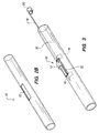
- FIG. 3 illustrates the guide member 10 inserted in the tissue supporting device 30 such that the loop 14 projects out through the rectangular side hole 32 and is retained in the hole.
- the guide member 10 is retained in the side hole 32 by the tabs 16 which are trapped between the tissue supporting device 30 and a balloon catheter assembly.
- the tissue supporting device 30 and guide member 10 are mounted on a catheter balloon 56 and the tissue supporting device 30 is crimped down onto the balloon in a known manner.
- the crimping process causes the strut elements 34 of the rectangular side hole 32 in the tissue supporting device 30 to close around the guide loop 10, locking the guide loop into place in the side hole.
- the crimping lug 22 of the guide loop 10 is crimped around the catheter 54 just below the proximal end of the balloon assembly, securing the guide member 10 to the catheter.
- the catheter and tissue supporting device assembly is now ready for insertion and deployment.
- the guide member 10 may take on other configurations as long as the guide member forms a short tube or loop positioned on or secured to the balloon/catheter assembly in such a way that it passes out through the side hole of the tissue supporting device when the device is crimped or otherwise secured on the balloon 56.
- the guide member may be formed from a plastic tube and secured directly to the balloon, such as, by an adhesive.
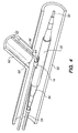
- a first guidewire 50 follows the main artery 60 as shown in FIG. 4, and a second guidewire 52 is inserted into the branch artery 62.
- the catheter 54 having the tissue supporting device 30 mounted on the balloon 56 at the distal end of the catheter is tracked over the main artery guidewire 50.
- the branch artery guidewire 52 is threaded through the guide loop 12 that projects through the top of the tissue supporting device 30.
- the assembly is then fed through a catheter guide tube (not shown) to the site of the bifurcation 68.
- the clevis 64 formed by the tissue supporting device 30 and the branch artery guidewire 52 comes to rest against the distal side 66 of the branch artery opening.
- the guide loop 14, and thus the side port 32 of the tissue supporting device 30 in which it is crimped, is now located directly under the branch artery opening, and the device is ready for deployment.
- the spacer 16 spaces the guide loop a predetermined distance from the distal edge of the side hole 32 so that the side hole will be properly aligned with the opening of the bifurcation 68.
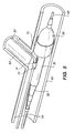
- tissue supporting device 30 To deploy the tissue supporting device 30, pressure is increased in the catheter balloon 56 until the distal end 70 of the tissue supporting device expands to the lumen diameter of the main artery 60. This procedure locks the tissue supporting device 30 in place in the desired radial and longitudinal orientation as shown in FIG. 5.
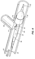
- the side branch guidewire 52 is withdrawn from the branch lumen 62 and the guide loop 14, and retracted to a position slightly behind the proximal end of the catheter balloon 56 as shown in FIG. 6.
- the side branch guidewire 52 is free to move back and forth longitudinally because the proximal end of the tissue supporting device 30 has not been expanded. It is desirable to withdraw the side branch guidewire 52 temporarily while completing expansion of the proximal end of the tissue supporting device 30 to avoid pinning the side branch guidewire between the expanded tissue supporting device 30 and the lumen wall. This is the reason that differential expansion capability is beneficial in the tissue supporting device 30.
- tissue supporting device 30 After withdrawal of the side branch guidewire 52, pressure in the catheter balloon 56 is increased further, until the side port area and the proximal end of the tissue supporting device 30 expand to their full extent. During expansion of the side port area, the spacer 16 and loop 14 maintain the longitudinal dimension of the side hole 32 and prevent longitudinal contraction of the side hole during expansion.
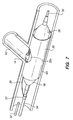
- the main artery tissue supporting device 30 is now fully deployed with a fully open side port 32a of specific geometry positioned over the branch lumen opening, and a full complement of strut elements deployed around the remainder of the artery opposite the side port to provide good tissue support as shown in FIG. 7.
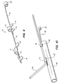
- the catheter balloon 56 is then deflated, allowing the guide member 10 to drop out of the enlarged side port 32a.
- the deflated catheter/balloon assembly is then withdrawn, pulling the guide member 10 along with it via the tether 18 and crimping lug 22 as shown in FIG. 8.
- the side branch guidewire 52 may be reinserted through the tissue supporting device enlarged side hole 32a and into the branch lumen 62 for subsequent procedures.
- the orientation accuracy of the delivery system can be improved by the addition of one or more auxiliary guide loops to the guide member as illustrated in FIGS. 9 and 10.
- the guide member 70 as shown in FIG. 9 includes the main loop 14 with the spacer section 16 and tabs 18, and an auxiliary loop 72.
- the auxiliary loop 72 is also provided with tabs 74 which conform generally to the inner radius of the unexpanded tissue supporting device in which the guide loop will be mounted.
- the auxiliary loop 72 is connected the main loop 14 by a first tether 76 and is connected to the crimping lug 22 by a second tether 78.
- the auxiliary loop 72 extends through a second side port feature 80 in the tissue supporting device 30.
- the additional one or more auxiliary loops 72 are located proximal to the primary guide loop 14.
- the installation procedure for the tissue supporting device 30 using the guide member 70 shown in FIGS. 9 and 10 would be performed in the same manner as discussed above with respect to the embodiment employing a single guide loop, however, the side branch guidewire 52 extends through both the main guide loop 14 and the auxiliary loop 72.
- tissue supporting device 30 One common procedure to follow implantation of the tissue supporting device 30 into the main lumen would be implantation of a second tissue supporting device in the branch lumen 62.
- a procedure very similar to the one just outlined could be used to accomplish this task, by simply reversing the roles of the main lumen and branch lumen guidewires.
- a guide member is inserted into the side port of a second tissue supporting device, and the assembly is crimped down on a conventional catheter balloon.
- the catheter and tissue supporting device assembly is mounted on the side branch guidewire 52, and the main artery guidewire 50 is threaded through the guide member.
- the entire assembly is fed to the bifurcation site, where the clevis formed by the tissue supporting device and main artery guidewire 50 comes to rest against the distal side of the branch lumen opening.
- the side-port border-struts of the previously implanted tissue supporting device 30 are also in place to provide an even more accurate stop for aligning the side hole edge of the incoming tissue supporting device at the distal side of the bifurcation.
- the tissue supporting device deployment sequence for deploying the second device would now proceed as before: the distal end of the branch tissue supporting device would be expanded in the branch artery, anchoring the tissue supporting device in position, and the main artery guidewire 50 would be retracted below the proximal end of the catheter balloon.
- the unexpanded proximal end of the second tissue supporting device now extends back into the main artery, with the tissue supporting device side port facing downstream in the main artery.
- the proximal end of the second tissue supporting device When expansion of the second tissue supporting device is completed, the proximal end of the second tissue supporting device will be implanted in the main artery, with the second tissue supporting device bent around the proximal side of the branch artery orifice.
- the side port of the second tissue supporting device will open exactly opposite this bend, since the leading edge of the side port was initially located at the bifurcation junction as described above.
- the side port thus opens to permit flow through the main artery, and the tissue supporting device struts arrayed opposite the side port provide support to the proximal side of the branch artery orifice (the bend area).
Landscapes
- Health & Medical Sciences (AREA)
- Engineering & Computer Science (AREA)
- Biomedical Technology (AREA)
- Life Sciences & Earth Sciences (AREA)
- Oral & Maxillofacial Surgery (AREA)
- Transplantation (AREA)
- Heart & Thoracic Surgery (AREA)
- Vascular Medicine (AREA)
- Cardiology (AREA)
- Animal Behavior & Ethology (AREA)
- General Health & Medical Sciences (AREA)
- Public Health (AREA)
- Veterinary Medicine (AREA)
- Media Introduction/Drainage Providing Device (AREA)
- Prostheses (AREA)
- External Artificial Organs (AREA)
Abstract
Description
- The present invention relates to a delivery system for delivering tissue supporting medical devices, and more particularly to a system for implanting expandable, non-removable devices at the junction of two or more bodily lumens in a living animal or human to support the organs and maintain patency.
- In the past, permanent or biodegradable devices have been developed for implantation within a body passageway to maintain patency of the passageway. These devices arc typically introduced percutaneously, and transported transluminally until positioned at a desired location within the body passageway. The devices are then expanded either mechanically, such as by the expansion of a mandrel or balloon positioned inside the device, or expand themselves by releasing stored energy upon actuation within the body. Once expanded within the lumen, these devices, called stents, become encapsulated within the body tissue and remain a permanent implant.
- Frequently, the area to be supported by such devices is located at or near the junction of two or more lumens, called a bifurcation. In coronary angioplasty procedures, for example, it has been estimated that 15% to 20% of cases involve reinforcing the area at the junction of two arteries. Conventional stent implantation at such a junction results in at least partial blockage of the branch artery, affecting blood flow and impeding access to the branch artery for further angioplasty procedures.
- Known techniques for treating bifurcations generally deliver a mesh tissue supporting device into the artery and position the device over the bifurcation. According to the known methods, a surgeon then attempts to create one or more branch lumen access holes by inserting a balloon through the sidewall of the mesh device, and then inflating the balloon to simply push the local features of the mesh aside. These techniques are inherently random in nature: the exact point of expansion in the device lattice cannot be predicted, and the device may or may not expand satisfactorily at that point. Tissue support provided by these known techniques for treating bifurcated arteries is similarly unpredictable. In addition, the effectiveness of such procedures is limited because many mesh devices are unable to accommodate such expansion at random locations in the device structure. Further, prior art tissue supporting device delivery systems are unable to accurately position specific device features over the branch artery opening.
- Prior art tissue supporting devices for bifurcations generally have not attempted to orient the device radially at the branch lumen opening. Rather, these stents included a section along their axis or at one end at which several enlarged expansion cells were distributed uniformly around the stent circumference. The presumption was that after stent insertion, one or the other of these cells would be oriented closely enough with the branch lumen opening that the subsequent procedures mentioned above would clear the opening. One example of such a device is the Jostent® bifurcation stent design which has an 8 cell circumferential construction over half the stent length and either 2 or 3 rows of larger cells which can be post-dilated to allow access for placement in a bifurcated vessel. One problem with this technique is that the resulting density of stent features at the area of the bifurcation is so low that there is very little stent strength around the rest of the circumference of the main artery for tissue support. Thus, the lumen junction area, which requires the greatest tissue support, actually gets the lowest support. For the same reason, such tissue supporting devices also provide a low ratio of tissue coverage (metal-to-tissue area ratio) in the junction area. Low metal coverage and the resulting tissue prolapse are associated with higher restenosis rates.
- Another method for deploying a stent in a bifurcating vessel is described in International Application WO98/19628. According to this method, a main stent having a substantially circular side opening and a flared stent having a flared end are used together to treat a bifurcating vessel in a two step process. In a first step, the main stent is positioned using an inflatable balloon catheter in the interior of the main stent and a stabilizing catheter extending through the side opening of the stent. The stabilizing catheter is used to place the side opening in the main stent at the opening to the branch vessel. The main stent is then expanded and the flared stent is inserted through the side opening into the vessel bifurcation. One drawback of this method is the difficulty in positioning the side opening of the main stent at a proper longitudinal and radial position at the vessel bifurcation. Another drawback of this system is the flared stent which is difficult to form and position, and may tend to protrude into the blood stream causing thrombosis.
- A system according to the preamble of claim 1 is known from EP-A-0 897 700.
- In view of the drawbacks of the prior art bifurcated tissue supporting systems, it would be advantageous to have a delivery system capable of accurately locating a side port feature of a tissue supporting device at a branch lumen opening, in both the longitudinal and radial directions.
- It would further be advantageous if the same delivery system could also be used to accurately install and orient a branch lumen second tissue supporting device.
- The invention includes expandable tissue supporting devices for use at lumen junctions or bifurcations, and a delivery system for accurately locating, orienting, and implanting the tissue supporting devices at the lumen junction or bifurcation.
- In accordance with the present invention, a system as defined in claim 1 is described for delivery of a tissue supporting device to a bifurcated body lumen. The system includes a catheter with an inflatable balloon configured to deliver an expandable tissue supporting device to the lumen, a guide member received on a side of the balloon and connected to the catheter, and a branch lumen guidewire extending along an exterior of the balloon and longitudinally slidable in the guide member.
- In accordance with a preferred embodiment of the invention, a guide member is described for use in delivery of a tissue supporting device to a bifurcated body lumen in a desired longitudinal and radial position. The guide member includes a guide loop for receiving a guidewire, means for securing the guide loop to a catheter, and at least one tab extending from the guide loop for holding the guide loop in position in a side hole of a tissue supporting device to be delivered.
- In accordance with a preferred use of the invention, a method of delivering of a tissue supporting device to a bifurcated body lumen includes the steps of:
- providing an expandable tissue supporting device in an unexpanded configuration, the tissue supporting device having a side hole;
- positioning a guide member in the side hole;
- positioning a side branch guidewire in a body lumen with a distal end of the side branch guidewire extending into a side branch of a bifurcation;
- delivering the tissue supporting device into the body lumen by tracking the guide member along the side branch guidewire;
- positioning the tissue supporting device with the side hole aligned radially and longitudinally with an opening of the side branch; and
- expanding the tissue supporting device.
- The invention will now be described in greater detail with reference to the preferred embodiments illustrated in the accompanying drawings, in which like elements bear like reference numerals, and wherein:
- FIG. 1 is a perspective view of a guide member;
- FIG. 2a is a side view of an unexpanded tissue supporting device with a side port, the device has been laid flat for ease of illustration;
- FIG. 2b is a simplified, perspective view of the cylindrical tissue supporting device of FIG. 2a;
- FIG. 3 is a perspective view of the guide member of FIG. 1 mounted in the side port of the tissue supporting device of FIGS. 2a and 2b;
- FIG. 4 is a perspective view of the tissue supporting device of FIGS. 2a and 2b as it is inserted to a junction of two arteries with a balloon catheter and two guidewires;
- FIG. 5 is a perspective view illustrating a first step of the implantation sequence: expansion of the distal end of the tissue supporting device;
- FIG. 6 is a perspective view illustrating a second step of the implantation sequence: withdrawal of the branch lumen guidewire;
- FIG. 7 is a perspective view illustrating a third step of the implantation sequence: expansion of the side port area and proximal end of the tissue supporting device;
- FIG. 8 is a perspective view illustrating a fourth step of the implantation sequence: deflation and withdrawal of the balloon and guide loop;
- FIG. 9 is a perspective view of a guide member with an auxiliary guide loop in accordance with the present invention; and
- FIG. 10 is a perspective view of the guide member of FIG. 9 mounted in a tissue supporting device having two side ports.
- The invention involves a system for delivery of a tissue supporting device to a bifurcated artery such that, on expansion, the tissue supporting device provides side ports of a specific size and geometry to accommodate bifurcations in the artery. The delivery system is capable of accurately orienting these side ports both radially and longitudinally with respect to branch lumen openings of the artery. The delivery system achieves orientation by utilizing a
guide member 10 which is positioned to extend from the side port feature of the tissue supporting device. The tissue support device is delivered to the artery on a balloon catheter which is used for expansion of the device. Theguide member 10 is tracked along a side branch guidewire which extends into the branch lumen, ultimately orienting the side port of the tissue supporting device properly at the branch lumen opening. While the tissue supporting device having the side port is expanded, theguide member 10 holds the tissue supporting device in the proper position. After expansion, theguide member 10 drops out of the enlarged side port and is withdrawn with the balloon catheter assembly. - FIG. 1 shows one embodiment of a
guide member 10 in accordance with the present invention. Thedevice 10 includes amain body 12 of which is preferably formed as a unitary piece comprising aloop 14, aspacer section 16, and twotabs 18. The inner diameter of theloop 14 is just large enough to provide clearance for a guidewire which will pass through the loop. Theloop 14,spacer section 16, andtabs 18 may be integrally formed from a single piece of tubing. The radius of thetabs 18 conforms generally to the inner radius of the unexpanded tissue supporting device in which the guide loop will be mounted. - The
main body 12 of theguide member 10 is attached to a crimpinglug 22 via a long,flexible tether 20. Thetether 20 can be a simple wire attached to themain body 12 and crimpinglug 22 at either end, or can be integrally formed from the same tube as themain body 12 and the crimpinglug 22. - The
guide member 10 is preferably made radiopaque by one of several available methods. For example, the wall thickness of the tube may be made thick enough for good radio opacity. Alternatively, the guide loop may be made from, plated, or coated with a radiopaque material. This is not objectionable since the guide member is withdrawn immediately after the procedure and does not become a permanent implant. When the radiopaque guide member is crimped into the side port of the tissue supporting device as described in further detail below, the exact location of the side port will be clearly visible on the fluoroscope. - A preferred tissue supporting device for use in the present invention provides several capabilities not normally found in conventional stents. The tissue supporting device should provide a side port feature which will securely clamp the
guide member 10 in the side port when the tissue supporting device itself is crimped to the catheter balloon. The side port should expand to some desired shape and release the guide member when the tissue supporting device is expanded. The tissue supporting device should also be capable of differential expansion; i.e. different areas of the device should expand at different balloon pressures, giving the device the ability to open in a specific sequence. - FIG. 2a shows a portion of one embodiment of a cylindrical, expandable
tissue supporting device 30 which has been laid flat for ease of illustration. Thedevice 30 of FIG. 2a is shown in an unexpanded configuration and includes a rectangular side hole orport 32. FIG. 2b shows a simplified cylindrical view of the expandabletissue supporting device 30 of FIG. 2a, with theside port feature 32 shown as a rectangular hole in one side. This embodiment of thetissue supporting device 30 relies on the use of ductile hinges which interconnect a plurality of struts to achieve the desired performance features. Tissue supporting devices of the type shown in FIG. 2a are described in further detail in U.S. Patent No. 6 241 762, and in U.S. Patent No. 6 293 967. - As shown in FIGS. 2a and 2b, the
side hole 32 initially takes the form of a rectangular hole in the unexpandedtissue supporting device 30. Theside hole 32 is bordered by six struts 34 that are in turn linked by ductile hinges 36. Therectangular side hole 32 fits the profile of theguide loop feature 10 closely, and the excellent crimping properties of the ductile hinges allow the hole to close tightly around the guide loop feature when thetissue supporting device 30 is crimped onto the catheter balloon. When thetissue supporting device 30 is expanded, such as by inflation of a balloon, theside hole feature 32 will expand to form an octagonal hole, releasing theguide member 10. - In the
tissue supporting device 30 of FIG. 2a, the ductile hinges 38 linking struts 40 on the left or proximal end of the device are wider than the ductile hinges 42 linking struts 44 on the right or distal end of the device. The width of the ductile hinges is measured in the circumferential direction of thedevice 30. As balloon pressure is increased during expansion of thedevice 30 the distal end of the device will open before the proximal end due to the different configuration of the ductile hinges at the two ends of the device. Thetissue supporting device 30 should be selected so that the device is capable of expansion beyond a nominal expansion which corresponds to an interior diameter of the lumen to be supported. This will ensure that thetissue supporting device 30 can be expanded to the desired diameter of the expanded lumen allowing for variations in artery diameters. Allowing for some additional expansion beyond the nominal expansion of thetissue support device 30 means that some of the struts around the circumference of the device will not reach their locking angle when the device has been installed. Accordingly, if thestruts 48 all open to their full extent before the struts 34 that border theside hole 32, this may result in the side hole not being fully opened when the tissue supporting device is installed. The partially opened side hole may partially block access to the branch artery. Accordingly, the ductile hinges 36 connecting the struts 34 that border theside hole 32 are preferably somewhat narrower than the ductile hinges 46 of the surrounding struts 48. This will guarantee that the hole feature opens to its final shape before the surroundingstruts 48 reach full expansion. - The present invention will be described with respect to a tissue supporting device having ductile hinges such as the device illustrated in FIG. 2a. However, it should be understood that the system according to the present invention may also be used for delivery of other known tissue supporting devices having side holes.
- FIG. 3 illustrates the
guide member 10 inserted in thetissue supporting device 30 such that theloop 14 projects out through therectangular side hole 32 and is retained in the hole. Theguide member 10 is retained in theside hole 32 by thetabs 16 which are trapped between thetissue supporting device 30 and a balloon catheter assembly. - As shown in FIG. 4, the
tissue supporting device 30 and guidemember 10 are mounted on acatheter balloon 56 and thetissue supporting device 30 is crimped down onto the balloon in a known manner. The crimping process causes the strut elements 34 of therectangular side hole 32 in thetissue supporting device 30 to close around theguide loop 10, locking the guide loop into place in the side hole. The crimpinglug 22 of theguide loop 10 is crimped around thecatheter 54 just below the proximal end of the balloon assembly, securing theguide member 10 to the catheter. The catheter and tissue supporting device assembly is now ready for insertion and deployment. - The
guide member 10 may take on other configurations as long as the guide member forms a short tube or loop positioned on or secured to the balloon/catheter assembly in such a way that it passes out through the side hole of the tissue supporting device when the device is crimped or otherwise secured on theballoon 56. For example, the guide member may be formed from a plastic tube and secured directly to the balloon, such as, by an adhesive. - Prior to insertion of the catheter and tissue supporting device assembly, two catheter guidewires are installed by the operator. A
first guidewire 50 follows themain artery 60 as shown in FIG. 4, and asecond guidewire 52 is inserted into thebranch artery 62. Thecatheter 54 having thetissue supporting device 30 mounted on theballoon 56 at the distal end of the catheter is tracked over themain artery guidewire 50. The branch artery guidewire 52 is threaded through theguide loop 12 that projects through the top of thetissue supporting device 30. The assembly is then fed through a catheter guide tube (not shown) to the site of thebifurcation 68. As the catheter assembly approaches thebifurcation 68, theclevis 64 formed by thetissue supporting device 30 and the branch artery guidewire 52 comes to rest against thedistal side 66 of the branch artery opening. Theguide loop 14, and thus theside port 32 of thetissue supporting device 30 in which it is crimped, is now located directly under the branch artery opening, and the device is ready for deployment. Thespacer 16 spaces the guide loop a predetermined distance from the distal edge of theside hole 32 so that the side hole will be properly aligned with the opening of thebifurcation 68. - To deploy the
tissue supporting device 30, pressure is increased in thecatheter balloon 56 until thedistal end 70 of the tissue supporting device expands to the lumen diameter of themain artery 60. This procedure locks thetissue supporting device 30 in place in the desired radial and longitudinal orientation as shown in FIG. 5. - Next, the side branch guidewire 52 is withdrawn from the
branch lumen 62 and theguide loop 14, and retracted to a position slightly behind the proximal end of thecatheter balloon 56 as shown in FIG. 6. The side branch guidewire 52 is free to move back and forth longitudinally because the proximal end of thetissue supporting device 30 has not been expanded. It is desirable to withdraw the side branch guidewire 52 temporarily while completing expansion of the proximal end of thetissue supporting device 30 to avoid pinning the side branch guidewire between the expandedtissue supporting device 30 and the lumen wall. This is the reason that differential expansion capability is beneficial in thetissue supporting device 30. - After withdrawal of the side branch guidewire 52, pressure in the
catheter balloon 56 is increased further, until the side port area and the proximal end of thetissue supporting device 30 expand to their full extent. During expansion of the side port area, thespacer 16 andloop 14 maintain the longitudinal dimension of theside hole 32 and prevent longitudinal contraction of the side hole during expansion. The main arterytissue supporting device 30 is now fully deployed with a fullyopen side port 32a of specific geometry positioned over the branch lumen opening, and a full complement of strut elements deployed around the remainder of the artery opposite the side port to provide good tissue support as shown in FIG. 7. - The
catheter balloon 56 is then deflated, allowing theguide member 10 to drop out of theenlarged side port 32a. The deflated catheter/balloon assembly is then withdrawn, pulling theguide member 10 along with it via thetether 18 and crimpinglug 22 as shown in FIG. 8. After the catheter/balloon/guide loop assembly has been withdrawn, the side branch guidewire 52 may be reinserted through the tissue supporting deviceenlarged side hole 32a and into thebranch lumen 62 for subsequent procedures. - The orientation accuracy of the delivery system can be improved by the addition of one or more auxiliary guide loops to the guide member as illustrated in FIGS. 9 and 10. The
guide member 70 as shown in FIG. 9 includes themain loop 14 with thespacer section 16 andtabs 18, and anauxiliary loop 72. Theauxiliary loop 72 is also provided withtabs 74 which conform generally to the inner radius of the unexpanded tissue supporting device in which the guide loop will be mounted. Theauxiliary loop 72 is connected themain loop 14 by afirst tether 76 and is connected to the crimpinglug 22 by asecond tether 78. As shown in FIG. 10, theauxiliary loop 72 extends through a secondside port feature 80 in thetissue supporting device 30. The additional one or moreauxiliary loops 72 are located proximal to theprimary guide loop 14. The installation procedure for thetissue supporting device 30 using theguide member 70 shown in FIGS. 9 and 10 would be performed in the same manner as discussed above with respect to the embodiment employing a single guide loop, however, the side branch guidewire 52 extends through both themain guide loop 14 and theauxiliary loop 72. - One common procedure to follow implantation of the
tissue supporting device 30 into the main lumen would be implantation of a second tissue supporting device in thebranch lumen 62. A procedure very similar to the one just outlined could be used to accomplish this task, by simply reversing the roles of the main lumen and branch lumen guidewires. As above, a guide member is inserted into the side port of a second tissue supporting device, and the assembly is crimped down on a conventional catheter balloon. In this case, the catheter and tissue supporting device assembly is mounted on the side branch guidewire 52, and the main artery guidewire 50 is threaded through the guide member. As before, the entire assembly is fed to the bifurcation site, where the clevis formed by the tissue supporting device and main artery guidewire 50 comes to rest against the distal side of the branch lumen opening. In this case, the side-port border-struts of the previously implantedtissue supporting device 30 are also in place to provide an even more accurate stop for aligning the side hole edge of the incoming tissue supporting device at the distal side of the bifurcation. - The tissue supporting device deployment sequence for deploying the second device would now proceed as before: the distal end of the branch tissue supporting device would be expanded in the branch artery, anchoring the tissue supporting device in position, and the main artery guidewire 50 would be retracted below the proximal end of the catheter balloon. The unexpanded proximal end of the second tissue supporting device now extends back into the main artery, with the tissue supporting device side port facing downstream in the main artery.
- When expansion of the second tissue supporting device is completed, the proximal end of the second tissue supporting device will be implanted in the main artery, with the second tissue supporting device bent around the proximal side of the branch artery orifice. The side port of the second tissue supporting device will open exactly opposite this bend, since the leading edge of the side port was initially located at the bifurcation junction as described above. The side port thus opens to permit flow through the main artery, and the tissue supporting device struts arrayed opposite the side port provide support to the proximal side of the branch artery orifice (the bend area). After implantation has been completed, the catheter/balloon/guide loop assembly is withdrawn, completing the procedure.
- Although the invention has been described with respect to providing support for bifurcated lumens in arteries, it should be understood that the invention may also be used to provide support for bifurcations in other bodily lumens.
- While the invention has been described in detail with reference to the preferred embodiments thereof, it will be apparent to one skilled in the art that various changes and modifications can be made, without departing from the present invention.
Claims (14)
- A system for delivery of a tissue supporting device (30) to a bifurcated body lumen (60,62), the system comprising:a catheter (54) with an inflatable balloon (56);a tissue supporting device (30) mounted on the balloon (56), the inflatable balloon (56) configured to deliver said expandable tissue supporting device (30) to the lumen (60,62);a guide member (10) received on a side of the balloon (56) and connected to the catheter (54); anda branch lumen guidewire (52) extending along an exterior of the balloon (56) and being longitudinally slidable in the guide member (10),characterized in that
the guide member comprises a guide loop (14), wherethrough the branch lumen guidewire (52) is slidable such that the branch lumen guidewire (52) extends along a radial exterior of the tissue supporting device (30) in a region proximal to the guide loop (14). - The system of Claim 1, wherein said tissue supporting device comprises a side hole (32), and said guide loop (14) is shorter than said side hole (32).
- The system of Claim 2, wherein the guide member (10) extends radially from the side of the balloon (56), and the guide loop (14) is arranged to be received in said side hole (32).
- The system of one of Claims 1 to 3, wherein the guide member (10) is positioned between the tissue supporting device (30) and the balloon (56) and is adapted to be crimped in place by crimping of the tissue supporting device (30) onto the balloon (56).
- The system of one Claims 1 to 4, wherein the guide member (10) includes a fastener (22) connected to the catheter (54).
- The system of Claim 5, wherein the fastener includes a crimping lug (22) which is connected to a body (12) of the guide member (10) by a tether (20).
- The system of one of Claims 1 to 6, wherein the guide member (10) further includes an auxiliary guide loop (72).
- The system of one of Claims 1 to 7, wherein said tissue supporting device (30) has differential expansion capability.
- The system of one of Claims 1 to 5, wherein the guide member (10) comprises means for securing the guide loop (14) to the catheter (54), and at least one tab (18) extending from said guide loop (14) for holding said guide loop (14) in position in the side hole (32) of the tissue supporting device (30) to be delivered.
- The system of Claim 9, wherein the at least one tab (18) is a curved member having a radius of curvature which corresponds substantially to an inner radius of the tissue supporting device (30) to be delivered.
- The system of Claim 10, wherein the guide loop (14) and at least one tab (18) are formed from a single piece of tubing.
- The system of one of Claims 9 to 11, wherein said means for securing the guide loop (14) to a catheter (54) includes a crimping lug (22) which is connected to the guide loop (14) by a tether (20).
- The system of one of Claims 9 to 12, further comprising a spacer member (16) connected to the guide loop (14) and configured to space the guide loop (14) a predetermined distance from a distal edge of the side hole (32) of the tissue supporting device (30) when the guide loop (14) is positioned in the side hole (32) of the tissue supporting device (30).
- The system of one of Claims 9 to 13, further comprising an auxiliary guide loop (72) positioned proximally of the guide loop (14).
Applications Claiming Priority (3)
| Application Number | Priority Date | Filing Date | Title |
|---|---|---|---|
| US315885 | 1999-05-20 | ||
| US09/315,885 US6290673B1 (en) | 1999-05-20 | 1999-05-20 | Expandable medical device delivery system and method |
| PCT/US2000/013264 WO2000071055A1 (en) | 1999-05-20 | 2000-05-12 | Expandable medical device delivery system and method |
Publications (2)
| Publication Number | Publication Date |
|---|---|
| EP1185214A1 EP1185214A1 (en) | 2002-03-13 |
| EP1185214B1 true EP1185214B1 (en) | 2006-10-11 |
Family
ID=23226490
Family Applications (1)
| Application Number | Title | Priority Date | Filing Date |
|---|---|---|---|
| EP00930734A Expired - Lifetime EP1185214B1 (en) | 1999-05-20 | 2000-05-12 | Expandable medical device delivery system |
Country Status (7)
| Country | Link |
|---|---|
| US (4) | US6290673B1 (en) |
| EP (1) | EP1185214B1 (en) |
| JP (1) | JP4198322B2 (en) |
| AT (1) | ATE342015T1 (en) |
| AU (1) | AU4850200A (en) |
| DE (1) | DE60031270T2 (en) |
| WO (1) | WO2000071055A1 (en) |
Families Citing this family (237)
| Publication number | Priority date | Publication date | Assignee | Title |
|---|---|---|---|---|
| US6783543B2 (en) * | 2000-06-05 | 2004-08-31 | Scimed Life Systems, Inc. | Intravascular stent with increasing coating retaining capacity |
| US6770092B2 (en) * | 1996-05-03 | 2004-08-03 | Medinol Ltd. | Method of delivering a bifurcated stent |
| US6440165B1 (en) * | 1996-05-03 | 2002-08-27 | Medinol, Ltd. | Bifurcated stent with improved side branch aperture and method of making same |
| US7641685B2 (en) * | 1996-05-03 | 2010-01-05 | Medinol Ltd. | System and method for delivering a bifurcated stent |
| US6599316B2 (en) | 1996-11-04 | 2003-07-29 | Advanced Stent Technologies, Inc. | Extendible stent apparatus |
| US7341598B2 (en) * | 1999-01-13 | 2008-03-11 | Boston Scientific Scimed, Inc. | Stent with protruding branch portion for bifurcated vessels |
| US6692483B2 (en) | 1996-11-04 | 2004-02-17 | Advanced Stent Technologies, Inc. | Catheter with attached flexible side sheath |
| US6325826B1 (en) | 1998-01-14 | 2001-12-04 | Advanced Stent Technologies, Inc. | Extendible stent apparatus |
| US6835203B1 (en) | 1996-11-04 | 2004-12-28 | Advanced Stent Technologies, Inc. | Extendible stent apparatus |
| DE69736676T2 (en) * | 1996-11-04 | 2007-01-11 | Advanced Stent Technologies, Inc., Pleasanton | EXPERIENCED DOUBLE STAR |
| US7591846B2 (en) | 1996-11-04 | 2009-09-22 | Boston Scientific Scimed, Inc. | Methods for deploying stents in bifurcations |
| US8211167B2 (en) | 1999-12-06 | 2012-07-03 | Boston Scientific Scimed, Inc. | Method of using a catheter with attached flexible side sheath |
| US6099497A (en) * | 1998-03-05 | 2000-08-08 | Scimed Life Systems, Inc. | Dilatation and stent delivery system for bifurcation lesions |
| US7208011B2 (en) * | 2001-08-20 | 2007-04-24 | Conor Medsystems, Inc. | Implantable medical device with drug filled holes |
| US7208010B2 (en) | 2000-10-16 | 2007-04-24 | Conor Medsystems, Inc. | Expandable medical device for delivery of beneficial agent |
| US6241762B1 (en) | 1998-03-30 | 2001-06-05 | Conor Medsystems, Inc. | Expandable medical device with ductile hinges |
| US7179289B2 (en) | 1998-03-30 | 2007-02-20 | Conor Medsystems, Inc. | Expandable medical device for delivery of beneficial agent |
| US20040254635A1 (en) | 1998-03-30 | 2004-12-16 | Shanley John F. | Expandable medical device for delivery of beneficial agent |
| US6293967B1 (en) | 1998-10-29 | 2001-09-25 | Conor Medsystems, Inc. | Expandable medical device with ductile hinges |
| US8257425B2 (en) | 1999-01-13 | 2012-09-04 | Boston Scientific Scimed, Inc. | Stent with protruding branch portion for bifurcated vessels |
| US20050060027A1 (en) * | 1999-01-13 | 2005-03-17 | Advanced Stent Technologies, Inc. | Catheter balloon systems and methods |
| US7655030B2 (en) | 2003-07-18 | 2010-02-02 | Boston Scientific Scimed, Inc. | Catheter balloon systems and methods |
| US7018401B1 (en) | 1999-02-01 | 2006-03-28 | Board Of Regents, The University Of Texas System | Woven intravascular devices and methods for making the same and apparatus for delivery of the same |
| US6290673B1 (en) * | 1999-05-20 | 2001-09-18 | Conor Medsystems, Inc. | Expandable medical device delivery system and method |
| US7387639B2 (en) * | 1999-06-04 | 2008-06-17 | Advanced Stent Technologies, Inc. | Short sleeve stent delivery catheter and methods |
| US20040097996A1 (en) | 1999-10-05 | 2004-05-20 | Omnisonics Medical Technologies, Inc. | Apparatus and method of removing occlusions using an ultrasonic medical device operating in a transverse mode |
| US20040158150A1 (en) * | 1999-10-05 | 2004-08-12 | Omnisonics Medical Technologies, Inc. | Apparatus and method for an ultrasonic medical device for tissue remodeling |
| US20060069423A1 (en) * | 1999-11-22 | 2006-03-30 | Fischell David R | Means and method for treating an intimal dissection after stent implantation |
| DE60134223D1 (en) * | 2000-05-09 | 2008-07-10 | Paieon Inc | SYSTEM AND METHOD FOR THREE DIMENTIONAL RECONSTRUCTION OF AN ARTERY |
| EP2111829B1 (en) * | 2000-06-05 | 2011-01-19 | Boston Scientific Limited | Intravascular stent with increasing coating retaining capacity |
| US7000230B1 (en) * | 2000-06-21 | 2006-02-14 | Microsoft Corporation | Network-based software extensions |
| DE60142131D1 (en) | 2000-10-16 | 2010-06-24 | Conor Medsystems Inc | Expandable medical device for releasing a remedy |
| US6764507B2 (en) | 2000-10-16 | 2004-07-20 | Conor Medsystems, Inc. | Expandable medical device with improved spatial distribution |
| EP1341443B1 (en) * | 2000-10-18 | 2010-12-29 | Paieon Inc. | System for positioning a device in a tubular organ |
| US20040073294A1 (en) | 2002-09-20 | 2004-04-15 | Conor Medsystems, Inc. | Method and apparatus for loading a beneficial agent into an expandable medical device |
| AU2002250189A1 (en) | 2001-02-26 | 2002-09-12 | Scimed Life Systems, Inc. | Bifurcated stent and delivery system |
| WO2002067815A1 (en) | 2001-02-26 | 2002-09-06 | Scimed Life Systems, Inc. | Bifurcated stent |
| US7799064B2 (en) | 2001-02-26 | 2010-09-21 | Boston Scientific Scimed, Inc. | Bifurcated stent and delivery system |
| US6749628B1 (en) | 2001-05-17 | 2004-06-15 | Advanced Cardiovascular Systems, Inc. | Stent and catheter assembly and method for treating bifurcations |
| US8337540B2 (en) | 2001-05-17 | 2012-12-25 | Advanced Cardiovascular Systems, Inc. | Stent for treating bifurcations and method of use |
| US8617231B2 (en) | 2001-05-18 | 2013-12-31 | Boston Scientific Scimed, Inc. | Dual guidewire exchange catheter system |
| US6679909B2 (en) * | 2001-07-31 | 2004-01-20 | Advanced Cardiovascular Systems, Inc. | Rapid exchange delivery system for self-expanding stent |
| US7842083B2 (en) | 2001-08-20 | 2010-11-30 | Innovational Holdings, Llc. | Expandable medical device with improved spatial distribution |
| US7056338B2 (en) * | 2003-03-28 | 2006-06-06 | Conor Medsystems, Inc. | Therapeutic agent delivery device with controlled therapeutic agent release rates |
| DE60229852D1 (en) * | 2001-08-23 | 2008-12-24 | Darrell C Gumm | ROTATING STENT FEEDING SYSTEM FOR INTRODUCING TO A SIDE BRANCH AND PROTECTION |
| GB0121980D0 (en) * | 2001-09-11 | 2001-10-31 | Cathnet Science Holding As | Expandable stent |
| US7578841B2 (en) | 2001-09-24 | 2009-08-25 | Boston Scientific Scimed, Inc. | Stent with protruding branch portion for bifurcated vessels |
| WO2006103644A1 (en) * | 2005-03-31 | 2006-10-05 | Paieon Inc. | Method and apparatus for positioning a device in a tubular organ |
| US7309350B2 (en) | 2001-12-03 | 2007-12-18 | Xtent, Inc. | Apparatus and methods for deployment of vascular prostheses |
| US7147656B2 (en) * | 2001-12-03 | 2006-12-12 | Xtent, Inc. | Apparatus and methods for delivery of braided prostheses |
| US7137993B2 (en) | 2001-12-03 | 2006-11-21 | Xtent, Inc. | Apparatus and methods for delivery of multiple distributed stents |
| US20040186551A1 (en) * | 2003-01-17 | 2004-09-23 | Xtent, Inc. | Multiple independent nested stent structures and methods for their preparation and deployment |
| US7182779B2 (en) * | 2001-12-03 | 2007-02-27 | Xtent, Inc. | Apparatus and methods for positioning prostheses for deployment from a catheter |
| US7351255B2 (en) * | 2001-12-03 | 2008-04-01 | Xtent, Inc. | Stent delivery apparatus and method |
| US8080048B2 (en) * | 2001-12-03 | 2011-12-20 | Xtent, Inc. | Stent delivery for bifurcated vessels |
| US7892273B2 (en) * | 2001-12-03 | 2011-02-22 | Xtent, Inc. | Custom length stent apparatus |
| US7294146B2 (en) | 2001-12-03 | 2007-11-13 | Xtent, Inc. | Apparatus and methods for delivery of variable length stents |
| US20030135266A1 (en) * | 2001-12-03 | 2003-07-17 | Xtent, Inc. | Apparatus and methods for delivery of multiple distributed stents |
| US7147661B2 (en) | 2001-12-20 | 2006-12-12 | Boston Scientific Santa Rosa Corp. | Radially expandable stent |
| US20050267407A1 (en) * | 2002-02-01 | 2005-12-01 | Vascular Designs, Inc. | Multi-function catheter and use thereof |
| AU2003214945A1 (en) * | 2002-02-01 | 2003-09-02 | Robert J. Goldman | Multi-function catheter and use thereof |
| US8062251B2 (en) * | 2002-02-01 | 2011-11-22 | Vascular Designs, Inc. | Multi-function catheter and use thereof |
| AU2003276920A1 (en) * | 2002-09-20 | 2004-04-08 | Innovational Holdings, Llc | Expandable medical device with openings for delivery of multiple beneficial agents |
| US7758636B2 (en) | 2002-09-20 | 2010-07-20 | Innovational Holdings Llc | Expandable medical device with openings for delivery of multiple beneficial agents |
| US7485139B1 (en) * | 2002-10-10 | 2009-02-03 | Ciamacco Jr Sam | Stent delivery and deployment system |
| US20040142014A1 (en) * | 2002-11-08 | 2004-07-22 | Conor Medsystems, Inc. | Method and apparatus for reducing tissue damage after ischemic injury |
| US20040143321A1 (en) * | 2002-11-08 | 2004-07-22 | Conor Medsystems, Inc. | Expandable medical device and method for treating chronic total occlusions with local delivery of an angiogenic factor |
| US7314480B2 (en) | 2003-02-27 | 2008-01-01 | Boston Scientific Scimed, Inc. | Rotating balloon expandable sheath bifurcation delivery |
| US7367989B2 (en) | 2003-02-27 | 2008-05-06 | Scimed Life Systems, Inc. | Rotating balloon expandable sheath bifurcation delivery |
| US20040202692A1 (en) * | 2003-03-28 | 2004-10-14 | Conor Medsystems, Inc. | Implantable medical device and method for in situ selective modulation of agent delivery |
| WO2004087214A1 (en) | 2003-03-28 | 2004-10-14 | Conor Medsystems, Inc. | Implantable medical device with beneficial agent concentration gradient |
| US20040225345A1 (en) * | 2003-05-05 | 2004-11-11 | Fischell Robert E. | Means and method for stenting bifurcated vessels |
| US7241308B2 (en) * | 2003-06-09 | 2007-07-10 | Xtent, Inc. | Stent deployment systems and methods |
| EP1654704A2 (en) * | 2003-07-21 | 2006-05-10 | Paieon Inc. | Method and system for identifying an optimal image within a series of images that depict a moving organ |
| US7959665B2 (en) | 2003-07-31 | 2011-06-14 | Abbott Cardiovascular Systems Inc. | Intravascular stent with inverted end rings |
| US8784472B2 (en) | 2003-08-15 | 2014-07-22 | Boston Scientific Scimed, Inc. | Clutch driven stent delivery system |
| US8298280B2 (en) | 2003-08-21 | 2012-10-30 | Boston Scientific Scimed, Inc. | Stent with protruding branch portion for bifurcated vessels |
| US7785653B2 (en) | 2003-09-22 | 2010-08-31 | Innovational Holdings Llc | Method and apparatus for loading a beneficial agent into an expandable medical device |
| US7742629B2 (en) * | 2003-09-25 | 2010-06-22 | Paieon Inc. | System and method for three-dimensional reconstruction of a tubular organ |
| US7553324B2 (en) * | 2003-10-14 | 2009-06-30 | Xtent, Inc. | Fixed stent delivery devices and methods |
| US20050080475A1 (en) * | 2003-10-14 | 2005-04-14 | Xtent, Inc. A Delaware Corporation | Stent delivery devices and methods |
| US20050096725A1 (en) | 2003-10-29 | 2005-05-05 | Pomeranz Mark L. | Expandable stent having removable slat members |
| US20050100577A1 (en) * | 2003-11-10 | 2005-05-12 | Parker Theodore L. | Expandable medical device with beneficial agent matrix formed by a multi solvent system |
| EP1689457A2 (en) * | 2003-11-10 | 2006-08-16 | Angiotech International Ag | Intravascular devices and fibrosis-inducing agents |
| WO2005046530A1 (en) * | 2003-11-12 | 2005-05-26 | Medtronic Vascular, Inc. | Coronary sinus approach for repair of mitral valve reguritation |
| US7344557B2 (en) | 2003-11-12 | 2008-03-18 | Advanced Stent Technologies, Inc. | Catheter balloon systems and methods |
| US7090694B1 (en) * | 2003-11-19 | 2006-08-15 | Advanced Cardiovascular Systems, Inc. | Portal design for stent for treating bifurcated vessels |
| US7867271B2 (en) | 2003-11-20 | 2011-01-11 | Advanced Cardiovascular Systems, Inc. | Rapid-exchange delivery systems for self-expanding stents |
| US7695491B2 (en) * | 2003-12-01 | 2010-04-13 | Ev3 Inc. | Rapid exchange catheters with tandem lumens |
| US7326236B2 (en) * | 2003-12-23 | 2008-02-05 | Xtent, Inc. | Devices and methods for controlling and indicating the length of an interventional element |
| US20070156225A1 (en) * | 2003-12-23 | 2007-07-05 | Xtent, Inc. | Automated control mechanisms and methods for custom length stent apparatus |
| US7686841B2 (en) | 2003-12-29 | 2010-03-30 | Boston Scientific Scimed, Inc. | Rotating balloon expandable sheath bifurcation delivery system |
| US7922753B2 (en) | 2004-01-13 | 2011-04-12 | Boston Scientific Scimed, Inc. | Bifurcated stent delivery system |
| US7794414B2 (en) * | 2004-02-09 | 2010-09-14 | Emigrant Bank, N.A. | Apparatus and method for an ultrasonic medical device operating in torsional and transverse modes |
| DE602005011105D1 (en) * | 2004-02-13 | 2009-01-02 | Conor Medsystems Inc | IMPLANTABLE DRUG DISPENSER WITH WIRE TUBES |
| US8012192B2 (en) | 2004-02-18 | 2011-09-06 | Boston Scientific Scimed, Inc. | Multi-stent delivery system |
| US7225518B2 (en) | 2004-02-23 | 2007-06-05 | Boston Scientific Scimed, Inc. | Apparatus for crimping a stent assembly |
| US7744619B2 (en) | 2004-02-24 | 2010-06-29 | Boston Scientific Scimed, Inc. | Rotatable catheter assembly |
| US7922740B2 (en) * | 2004-02-24 | 2011-04-12 | Boston Scientific Scimed, Inc. | Rotatable catheter assembly |
| US7766951B2 (en) * | 2004-03-04 | 2010-08-03 | Y Med, Inc. | Vessel treatment devices |
| US9050437B2 (en) | 2004-03-04 | 2015-06-09 | YMED, Inc. | Positioning device for ostial lesions |
| US7780715B2 (en) | 2004-03-04 | 2010-08-24 | Y Med, Inc. | Vessel treatment devices |
| US7753951B2 (en) * | 2004-03-04 | 2010-07-13 | Y Med, Inc. | Vessel treatment devices |
| US20050209673A1 (en) * | 2004-03-04 | 2005-09-22 | Y Med Inc. | Bifurcation stent delivery devices |
| US8007528B2 (en) | 2004-03-17 | 2011-08-30 | Boston Scientific Scimed, Inc. | Bifurcated stent |
| US7323006B2 (en) * | 2004-03-30 | 2008-01-29 | Xtent, Inc. | Rapid exchange interventional devices and methods |
| US20050222672A1 (en) * | 2004-04-01 | 2005-10-06 | Cappella, Inc. | Ostial stent |
| US20050228477A1 (en) * | 2004-04-09 | 2005-10-13 | Xtent, Inc. | Topographic coatings and coating methods for medical devices |
| US20060122686A1 (en) * | 2004-05-10 | 2006-06-08 | Ran Gilad | Stent and method of manufacturing same |
| US20060122692A1 (en) * | 2004-05-10 | 2006-06-08 | Ran Gilad | Stent valve and method of using same |
| US20060122693A1 (en) * | 2004-05-10 | 2006-06-08 | Youssef Biadillah | Stent valve and method of manufacturing same |
| US20050288766A1 (en) | 2004-06-28 | 2005-12-29 | Xtent, Inc. | Devices and methods for controlling expandable prostheses during deployment |
| US8317859B2 (en) | 2004-06-28 | 2012-11-27 | J.W. Medical Systems Ltd. | Devices and methods for controlling expandable prostheses during deployment |
| US20060079956A1 (en) * | 2004-09-15 | 2006-04-13 | Conor Medsystems, Inc. | Bifurcation stent with crushable end and method for delivery of a stent to a bifurcation |
| US20060074285A1 (en) * | 2004-09-24 | 2006-04-06 | Paieon Inc. | Apparatus and method for fusion and in-operating-room presentation of volumetric data and 3-D angiographic data |
| US20060069424A1 (en) * | 2004-09-27 | 2006-03-30 | Xtent, Inc. | Self-constrained segmented stents and methods for their deployment |
| US7156871B2 (en) * | 2004-10-28 | 2007-01-02 | Cordis Neurovascular, Inc. | Expandable stent having a stabilized portion |
| US7147659B2 (en) * | 2004-10-28 | 2006-12-12 | Cordis Neurovascular, Inc. | Expandable stent having a dissolvable portion |
| CA2598164C (en) * | 2004-12-08 | 2013-10-08 | Innovational Holdings Llc | Expandable medical device with differential hinge performance |
| US9427340B2 (en) | 2004-12-14 | 2016-08-30 | Boston Scientific Scimed, Inc. | Stent with protruding branch portion for bifurcated vessels |
| US8353944B2 (en) * | 2005-03-14 | 2013-01-15 | Boston Scientific Scimed, Inc. | Bifurcation delivery system |
| US8295577B2 (en) | 2005-03-31 | 2012-10-23 | Michael Zarkh | Method and apparatus for guiding a device in a totally occluded or partly occluded tubular organ |
| US7402168B2 (en) * | 2005-04-11 | 2008-07-22 | Xtent, Inc. | Custom-length stent delivery system with independently operable expansion elements |
| US8480728B2 (en) | 2005-05-26 | 2013-07-09 | Boston Scientific Scimed, Inc. | Stent side branch deployment initiation geometry |
| US8317855B2 (en) | 2005-05-26 | 2012-11-27 | Boston Scientific Scimed, Inc. | Crimpable and expandable side branch cell |
| US20060271161A1 (en) * | 2005-05-26 | 2006-11-30 | Boston Scientific Scimed, Inc. | Selective treatment of stent side branch petals |
| US20070043422A1 (en) * | 2005-08-18 | 2007-02-22 | Cappella, Inc. | Delivery system and method of use for accurate positioning of a device in a bifurcation |
| US20070050016A1 (en) * | 2005-08-29 | 2007-03-01 | Boston Scientific Scimed, Inc. | Stent with expanding side branch geometry |
| US7955374B2 (en) * | 2005-09-02 | 2011-06-07 | Medtronic Vascular, Inc. | Modular branch vessel stent-graft assembly |
| US7731741B2 (en) | 2005-09-08 | 2010-06-08 | Boston Scientific Scimed, Inc. | Inflatable bifurcation stent |
| US8043366B2 (en) | 2005-09-08 | 2011-10-25 | Boston Scientific Scimed, Inc. | Overlapping stent |
| US8038706B2 (en) | 2005-09-08 | 2011-10-18 | Boston Scientific Scimed, Inc. | Crown stent assembly |
| US20070088428A1 (en) * | 2005-09-15 | 2007-04-19 | Cappella, Inc. | Intraluminal device with asymmetric cap portion |
| US20070112418A1 (en) | 2005-11-14 | 2007-05-17 | Boston Scientific Scimed, Inc. | Stent with spiral side-branch support designs |
| US8435284B2 (en) | 2005-12-14 | 2013-05-07 | Boston Scientific Scimed, Inc. | Telescoping bifurcated stent |
| US8343211B2 (en) | 2005-12-14 | 2013-01-01 | Boston Scientific Scimed, Inc. | Connectors for bifurcated stent |
| US20070142819A1 (en) * | 2005-12-20 | 2007-06-21 | El-Nounou Fozan O | Bifurcated catheter for agent delivery and method of agent delivery |
| US20070142904A1 (en) * | 2005-12-20 | 2007-06-21 | Boston Scientific Scimed, Inc. | Bifurcated stent with multiple locations for side branch access |
| US7540881B2 (en) | 2005-12-22 | 2009-06-02 | Boston Scientific Scimed, Inc. | Bifurcation stent pattern |
| US20070179587A1 (en) * | 2006-01-30 | 2007-08-02 | Xtent, Inc. | Apparatus and methods for deployment of custom-length prostheses |
| US8821561B2 (en) | 2006-02-22 | 2014-09-02 | Boston Scientific Scimed, Inc. | Marker arrangement for bifurcation catheter |
| US20070208419A1 (en) * | 2006-03-06 | 2007-09-06 | Boston Scientific Scimed, Inc. | Bifurcation stent with uniform side branch projection |
| US20070208415A1 (en) * | 2006-03-06 | 2007-09-06 | Kevin Grotheim | Bifurcated stent with controlled drug delivery |
| US20070208411A1 (en) * | 2006-03-06 | 2007-09-06 | Boston Scientific Scimed, Inc. | Bifurcated stent with surface area gradient |
| US20070208414A1 (en) * | 2006-03-06 | 2007-09-06 | Shawn Sorenson | Tapered strength rings on a bifurcated stent petal |
| US7833264B2 (en) | 2006-03-06 | 2010-11-16 | Boston Scientific Scimed, Inc. | Bifurcated stent |
| US8298278B2 (en) | 2006-03-07 | 2012-10-30 | Boston Scientific Scimed, Inc. | Bifurcated stent with improvement securement |
| US20070260224A1 (en) * | 2006-03-09 | 2007-11-08 | Abbott Laboratories | Flexible catheter tip having a shaped head |
| US8167929B2 (en) * | 2006-03-09 | 2012-05-01 | Abbott Laboratories | System and method for delivering a stent to a bifurcated vessel |
| US20070270933A1 (en) * | 2006-03-09 | 2007-11-22 | Abbott Laboratories | Stent having contoured proximal end |
| JP2009530060A (en) | 2006-03-20 | 2009-08-27 | エックステント・インコーポレーテッド | Apparatus and method for deploying connected prosthetic segments |
| US20070225798A1 (en) * | 2006-03-23 | 2007-09-27 | Daniel Gregorich | Side branch stent |
| US8043358B2 (en) * | 2006-03-29 | 2011-10-25 | Boston Scientific Scimed, Inc. | Stent with overlap and high extension |
| US8348991B2 (en) * | 2006-03-29 | 2013-01-08 | Boston Scientific Scimed, Inc. | Stent with overlap and high expansion |
| US20070233233A1 (en) * | 2006-03-31 | 2007-10-04 | Boston Scientific Scimed, Inc | Tethered expansion columns for controlled stent expansion |
| US20070260304A1 (en) * | 2006-05-02 | 2007-11-08 | Daniel Gregorich | Bifurcated stent with minimally circumferentially projected side branch |
| US7744643B2 (en) | 2006-05-04 | 2010-06-29 | Boston Scientific Scimed, Inc. | Displaceable stent side branch structure |
| US8486025B2 (en) | 2006-05-11 | 2013-07-16 | Ronald J. Solar | Systems and methods for treating a vessel using focused force |
| US7901378B2 (en) * | 2006-05-11 | 2011-03-08 | Y-Med, Inc. | Systems and methods for treating a vessel using focused force |
| US8241246B2 (en) * | 2006-05-22 | 2012-08-14 | Abbott Laboratories Vascular Enterprises Ltd. | Side by side lumen catheter and method of manufacture thereof |
| US20080097620A1 (en) * | 2006-05-26 | 2008-04-24 | Nanyang Technological University | Implantable article, method of forming same and method for reducing thrombogenicity |
| US20070281117A1 (en) * | 2006-06-02 | 2007-12-06 | Xtent, Inc. | Use of plasma in formation of biodegradable stent coating |
| US20070293878A1 (en) * | 2006-06-16 | 2007-12-20 | Butsch John L | Magnetic mesh support for tissue walls |
| EP2051673A2 (en) | 2006-06-23 | 2009-04-29 | Boston Scientific Limited | Bifurcated stent with twisted hinges |
| US8029558B2 (en) | 2006-07-07 | 2011-10-04 | Abbott Cardiovascular Systems, Inc. | Stent and catheter assembly and method for treating bifurcations |
| US20080269865A1 (en) * | 2006-08-07 | 2008-10-30 | Xtent, Inc. | Custom Length Stent Apparatus |
| US8834554B2 (en) * | 2006-08-22 | 2014-09-16 | Abbott Cardiovascular Systems Inc. | Intravascular stent |
| US8882826B2 (en) * | 2006-08-22 | 2014-11-11 | Abbott Cardiovascular Systems Inc. | Intravascular stent |
| US8216267B2 (en) | 2006-09-12 | 2012-07-10 | Boston Scientific Scimed, Inc. | Multilayer balloon for bifurcated stent delivery and methods of making and using the same |
| US20080077218A1 (en) * | 2006-09-25 | 2008-03-27 | Boston Scientific Scimed, Inc. | Injection of therapeutic into porous regions of a medical device |
| US7780730B2 (en) | 2006-09-25 | 2010-08-24 | Iyad Saidi | Nasal implant introduced through a non-surgical injection technique |
| US7951191B2 (en) | 2006-10-10 | 2011-05-31 | Boston Scientific Scimed, Inc. | Bifurcated stent with entire circumferential petal |
| RU2454205C2 (en) | 2006-10-22 | 2012-06-27 | Айдев Текнолоджиз, Инк. | Methods for fastening of thread ends and resulting devices |
| KR101659197B1 (en) | 2006-10-22 | 2016-09-22 | 이데브 테크놀로지스, 아이엔씨. | Devices and methods for stent advancement |
| US7871396B2 (en) * | 2006-10-30 | 2011-01-18 | Boston Scientific Scimed, Inc. | Bifurcation catheter assembly and method |
| US8206429B2 (en) | 2006-11-02 | 2012-06-26 | Boston Scientific Scimed, Inc. | Adjustable bifurcation catheter incorporating electroactive polymer and methods of making and using the same |
| US7842082B2 (en) | 2006-11-16 | 2010-11-30 | Boston Scientific Scimed, Inc. | Bifurcated stent |
| US20080140179A1 (en) * | 2006-12-12 | 2008-06-12 | Ladisa John F | Apparatus and method for minimizing flow disturbances in a stented region of a lumen |
| US7959668B2 (en) * | 2007-01-16 | 2011-06-14 | Boston Scientific Scimed, Inc. | Bifurcated stent |
| US20080199510A1 (en) | 2007-02-20 | 2008-08-21 | Xtent, Inc. | Thermo-mechanically controlled implants and methods of use |
| US8486132B2 (en) | 2007-03-22 | 2013-07-16 | J.W. Medical Systems Ltd. | Devices and methods for controlling expandable prostheses during deployment |
| US8118861B2 (en) | 2007-03-28 | 2012-02-21 | Boston Scientific Scimed, Inc. | Bifurcation stent and balloon assemblies |
| US8647376B2 (en) | 2007-03-30 | 2014-02-11 | Boston Scientific Scimed, Inc. | Balloon fold design for deployment of bifurcated stent petal architecture |
| US8486134B2 (en) | 2007-08-01 | 2013-07-16 | Boston Scientific Scimed, Inc. | Bifurcation treatment system and methods |
| US7959669B2 (en) | 2007-09-12 | 2011-06-14 | Boston Scientific Scimed, Inc. | Bifurcated stent with open ended side branch support |
| US20090076591A1 (en) * | 2007-09-19 | 2009-03-19 | Boston Scientific Scimed, Inc. | Stent Design Allowing Extended Release of Drug and/or Enhanced Adhesion of Polymer to OD Surface |
| US20090076584A1 (en) * | 2007-09-19 | 2009-03-19 | Xtent, Inc. | Apparatus and methods for deployment of multiple custom-length prostheses |
| US7833266B2 (en) | 2007-11-28 | 2010-11-16 | Boston Scientific Scimed, Inc. | Bifurcated stent with drug wells for specific ostial, carina, and side branch treatment |
| US7972373B2 (en) | 2007-12-19 | 2011-07-05 | Advanced Technologies And Regenerative Medicine, Llc | Balloon expandable bioabsorbable stent with a single stress concentration region interconnecting adjacent struts |
| US8277501B2 (en) | 2007-12-21 | 2012-10-02 | Boston Scientific Scimed, Inc. | Bi-stable bifurcated stent petal geometry |
| EP2231030B1 (en) | 2007-12-21 | 2019-02-27 | MicroVention, Inc. | System and method for locating detachment zone of a detachable implant |
| CN102036619B (en) | 2007-12-21 | 2014-07-23 | 微排放器公司 | A system and method of detecting implant detachment |
| US8747456B2 (en) | 2007-12-31 | 2014-06-10 | Boston Scientific Scimed, Inc. | Bifurcation stent delivery system and methods |
| US8221494B2 (en) | 2008-02-22 | 2012-07-17 | Endologix, Inc. | Apparatus and method of placement of a graft or graft system |
| US9101503B2 (en) * | 2008-03-06 | 2015-08-11 | J.W. Medical Systems Ltd. | Apparatus having variable strut length and methods of use |
| US8333003B2 (en) | 2008-05-19 | 2012-12-18 | Boston Scientific Scimed, Inc. | Bifurcation stent crimping systems and methods |
| US8932340B2 (en) | 2008-05-29 | 2015-01-13 | Boston Scientific Scimed, Inc. | Bifurcated stent and delivery system |
| US8377108B2 (en) | 2008-06-02 | 2013-02-19 | Boston Scientific Scimed, Inc. | Staggered two balloon bifurcation catheter assembly and methods |
| EP2300093B1 (en) | 2008-06-05 | 2016-04-20 | Boston Scientific Scimed, Inc. | Deflatable bifurcated device |
| WO2009149405A1 (en) | 2008-06-05 | 2009-12-10 | Boston Scientific Scimed, Inc. | Balloon bifurcated lumen treatment |
| US8206635B2 (en) | 2008-06-20 | 2012-06-26 | Amaranth Medical Pte. | Stent fabrication via tubular casting processes |
| US10898620B2 (en) | 2008-06-20 | 2021-01-26 | Razmodics Llc | Composite stent having multi-axial flexibility and method of manufacture thereof |
| US8206636B2 (en) | 2008-06-20 | 2012-06-26 | Amaranth Medical Pte. | Stent fabrication via tubular casting processes |
| US8133199B2 (en) | 2008-08-27 | 2012-03-13 | Boston Scientific Scimed, Inc. | Electroactive polymer activation system for a medical device |
| US8900207B2 (en) * | 2008-08-29 | 2014-12-02 | Barry F. Uretsky | Apparatus and method for treatment of bifurcation lesions |
| US11298252B2 (en) | 2008-09-25 | 2022-04-12 | Advanced Bifurcation Systems Inc. | Stent alignment during treatment of a bifurcation |
| US8821562B2 (en) | 2008-09-25 | 2014-09-02 | Advanced Bifurcation Systems, Inc. | Partially crimped stent |
| CA2739007C (en) | 2008-09-25 | 2017-10-31 | Advanced Bifurcation Systems Inc. | Partially crimped stent |
| US12076258B2 (en) | 2008-09-25 | 2024-09-03 | Advanced Bifurcation Systems Inc. | Selective stent crimping |
| US8828071B2 (en) | 2008-09-25 | 2014-09-09 | Advanced Bifurcation Systems, Inc. | Methods and systems for ostial stenting of a bifurcation |
| US9597220B2 (en) | 2008-11-19 | 2017-03-21 | Spirox, Inc. | Apparatus and methods for correcting nasal valve collapse |
| US8292940B2 (en) * | 2009-02-11 | 2012-10-23 | Boston Scientific Scimed, Inc. | Medical device having a rotatable shaft |
| US8398658B2 (en) | 2009-02-21 | 2013-03-19 | Farideh Roshanali | Device and procedure for minimally invasive closure of atrial septal defect without cardiopulmonary bypass |
| US8945202B2 (en) | 2009-04-28 | 2015-02-03 | Endologix, Inc. | Fenestrated prosthesis |
| US20100292777A1 (en) * | 2009-05-13 | 2010-11-18 | Boston Scientific Scimed, Inc. | Stent |
| US20100318170A1 (en) * | 2009-06-15 | 2010-12-16 | Richard Newhauser | Proximal catheter flap for managing wire twist |
| CA2789420A1 (en) | 2010-02-10 | 2011-08-18 | Okamura Corporation | Stretching structure of upholstery material for a chair |
| WO2011119884A1 (en) | 2010-03-24 | 2011-09-29 | Advanced Bifurcation Systems, Inc | System and methods for treating a bifurcation |
| EP2549958A4 (en) | 2010-03-24 | 2016-09-14 | Advanced Bifurcation Systems Inc | Methods and systems for treating a bifurcation with provisional side branch stenting |
| CA2794078A1 (en) | 2010-03-24 | 2011-09-29 | Advanced Bifurcation Systems, Inc. | Stent alignment during treatment of a bifurcation |
| US9561125B2 (en) | 2010-04-14 | 2017-02-07 | Microvention, Inc. | Implant delivery device |
| US9402754B2 (en) | 2010-05-18 | 2016-08-02 | Abbott Cardiovascular Systems, Inc. | Expandable endoprostheses, systems, and methods for treating a bifurcated lumen |
| US9023095B2 (en) | 2010-05-27 | 2015-05-05 | Idev Technologies, Inc. | Stent delivery system with pusher assembly |
| US20120109279A1 (en) | 2010-11-02 | 2012-05-03 | Endologix, Inc. | Apparatus and method of placement of a graft or graft system |
| WO2012109365A1 (en) | 2011-02-08 | 2012-08-16 | Advanced Bifurcation Systems, Inc. | System and methods for treating a bifurcation with a fully crimped stent |
| CA2826760A1 (en) | 2011-02-08 | 2012-08-16 | Advanced Bifurcation Systems, Inc. | Multi-stent and multi-balloon apparatus for treating bifurcations and methods of use |
| CA3161309A1 (en) | 2013-02-27 | 2014-09-04 | Spirox, Inc. | Nasal implants and systems and methods of use |
| CN203829102U (en) * | 2013-10-09 | 2014-09-17 | 唐利龙 | Support for preformed guide-wire channel |
| EP3185819A4 (en) | 2014-08-26 | 2018-03-14 | Spirox, Inc. | Nasal implants and systems and method of use |
| JP2018524025A (en) | 2015-06-30 | 2018-08-30 | エンドロジックス、インク | Lock assembly for coupling guidewire to delivery system |
| CN105031798A (en) * | 2015-08-06 | 2015-11-11 | 成都迅德科技有限公司 | Medical positioning apparatus |
| CN113349985A (en) | 2015-09-25 | 2021-09-07 | 斯贝洛克斯公司 | Nasal implants and systems and methods of use |
| US10639456B2 (en) | 2015-09-28 | 2020-05-05 | Microvention, Inc. | Guidewire with torque transmission element |
| EP3451894B1 (en) | 2016-05-02 | 2023-11-15 | Entellus Medical, Inc. | Nasal valve implants |
| CN106361389A (en) * | 2016-11-02 | 2017-02-01 | 凌安东 | Full-sealing communicating supporting device for hysteroscope operation |
| US10350395B2 (en) * | 2017-06-23 | 2019-07-16 | Cook Medical Technologies Llc | Introducer for lumen support or dilation |
| CN113769243B (en) | 2021-11-09 | 2022-02-15 | 东莞天天向上医疗科技有限公司 | Multi-guide-wire balloon dilatation catheter structure, dilatation catheter mechanism and medical equipment |
Family Cites Families (232)
| Publication number | Priority date | Publication date | Assignee | Title |
|---|---|---|---|---|
| US598457A (en) * | 1897-09-01 | 1898-02-01 | Amos Woeber | plating-machine |
| US698186A (en) | 1901-10-24 | 1902-04-22 | Dwiggins Wire Fence Company | Wire-fence machine. |
| US3657744A (en) | 1970-05-08 | 1972-04-25 | Univ Minnesota | Method for fixing prosthetic implants in a living body |
| US5876419A (en) * | 1976-10-02 | 1999-03-02 | Navius Corporation | Stent and method for making a stent |
| US5643314A (en) | 1995-11-13 | 1997-07-01 | Navius Corporation | Self-expanding stent |
| US4300244A (en) | 1979-09-19 | 1981-11-17 | Carbomedics, Inc. | Cardiovascular grafts |
| US4531936A (en) | 1981-01-29 | 1985-07-30 | Gordon Robert T | Device and method for the selective delivery of drugs to the myocardium |
| US5441745A (en) | 1982-03-30 | 1995-08-15 | Vestar, Inc. | Method of delivering micellular particles encapsulating chemotherapeutic agents to tumors in a body |
| US4542025A (en) | 1982-07-29 | 1985-09-17 | The Stolle Research And Development Corporation | Injectable, long-acting microparticle formulation for the delivery of anti-inflammatory agents |
| US4834755A (en) | 1983-04-04 | 1989-05-30 | Pfizer Hospital Products Group, Inc. | Triaxially-braided fabric prosthesis |
| US4580568A (en) | 1984-10-01 | 1986-04-08 | Cook, Incorporated | Percutaneous endovascular stent and method for insertion thereof |
| US4824436A (en) | 1985-04-09 | 1989-04-25 | Harvey Wolinsky | Method for the prevention of restenosis |
| US4650466A (en) | 1985-11-01 | 1987-03-17 | Angiobrade Partners | Angioplasty device |
| US4733665C2 (en) | 1985-11-07 | 2002-01-29 | Expandable Grafts Partnership | Expandable intraluminal graft and method and apparatus for implanting an expandable intraluminal graft |
| US5102417A (en) | 1985-11-07 | 1992-04-07 | Expandable Grafts Partnership | Expandable intraluminal graft, and method and apparatus for implanting an expandable intraluminal graft |
| US4955878A (en) | 1986-04-04 | 1990-09-11 | Biotechnology, Inc. | Kit for preventing or treating arterial dysfunction resulting from angioplasty procedures |
| JPH0763489B2 (en) | 1986-10-31 | 1995-07-12 | 宇部興産株式会社 | Medical tube |
| US4800882A (en) | 1987-03-13 | 1989-01-31 | Cook Incorporated | Endovascular stent and delivery system |
| US5059211A (en) | 1987-06-25 | 1991-10-22 | Duke University | Absorbable vascular stent |
| US4969458A (en) | 1987-07-06 | 1990-11-13 | Medtronic, Inc. | Intracoronary stent and method of simultaneous angioplasty and stent implant |
| US5460817A (en) | 1988-01-19 | 1995-10-24 | Allied Colloids Ltd. | Particulate composition comprising a core of matrix polymer with active ingredient distributed therein |
| US5157049A (en) | 1988-03-07 | 1992-10-20 | The United States Of America As Represented By The Department Of Health & Human Services | Method of treating cancers sensitive to treatment with water soluble derivatives of taxol |
| DE68927479T2 (en) | 1988-05-02 | 1997-04-03 | Phanos Tech Inc | CONNECTIONS, COMPOSITIONS AND METHOD FOR BINDING ORGANIC AFFECTION SUBSTANCES TO SURFACE MEMBRANES OF BIOPARTICLES |
| US4989601A (en) | 1988-05-02 | 1991-02-05 | Medical Engineering & Development Institute, Inc. | Method, apparatus, and substance for treating tissue having neoplastic cells |
| JPH0255064A (en) | 1988-08-03 | 1990-02-23 | Toa O | Skin removal for throm bus in blood vessel using catheter and throm bus removing system in blood vessel using catheter |
| US5213580A (en) | 1988-08-24 | 1993-05-25 | Endoluminal Therapeutics, Inc. | Biodegradable polymeric endoluminal sealing process |
| US5019090A (en) | 1988-09-01 | 1991-05-28 | Corvita Corporation | Radially expandable endoprosthesis and the like |
| US5053048A (en) | 1988-09-22 | 1991-10-01 | Cordis Corporation | Thromboresistant coating |
| CA1322628C (en) | 1988-10-04 | 1993-10-05 | Richard A. Schatz | Expandable intraluminal graft |
| LU87410A1 (en) | 1988-12-20 | 1990-07-10 | Cird | COSMETIC OR PHARMACEUTICAL COMPOSITION CONTAINING POLYMERIC OR FATTY BODY MICROSPHERES CHARGED WITH AT LEAST ONE ACTIVE PRODUCT |
| CH678393A5 (en) | 1989-01-26 | 1991-09-13 | Ulrich Prof Dr Med Sigwart | |
| US5078726A (en) | 1989-02-01 | 1992-01-07 | Kreamer Jeffry W | Graft stent and method of repairing blood vessels |
| US4960790A (en) | 1989-03-09 | 1990-10-02 | University Of Kansas | Derivatives of taxol, pharmaceutical compositions thereof and methods for the preparation thereof |
| US4990155A (en) | 1989-05-19 | 1991-02-05 | Wilkoff Howard M | Surgical stent method and apparatus |
| US4994071A (en) | 1989-05-22 | 1991-02-19 | Cordis Corporation | Bifurcating stent apparatus and method |
| US5171262A (en) | 1989-06-15 | 1992-12-15 | Cordis Corporation | Non-woven endoprosthesis |
| US5674278A (en) | 1989-08-24 | 1997-10-07 | Arterial Vascular Engineering, Inc. | Endovascular support device |
| US5059166A (en) | 1989-12-11 | 1991-10-22 | Medical Innovative Technologies R & D Limited Partnership | Intra-arterial stent with the capability to inhibit intimal hyperplasia |
| US5176617A (en) | 1989-12-11 | 1993-01-05 | Medical Innovative Technologies R & D Limited Partnership | Use of a stent with the capability to inhibit malignant growth in a vessel such as a biliary duct |
| US5304121A (en) | 1990-12-28 | 1994-04-19 | Boston Scientific Corporation | Drug delivery system making use of a hydrogel polymer coating |
| US5439446A (en) | 1994-06-30 | 1995-08-08 | Boston Scientific Corporation | Stent and therapeutic delivery system |
| US5049132A (en) | 1990-01-08 | 1991-09-17 | Cordis Corporation | Balloon catheter for delivering therapeutic agents |
| ATE120377T1 (en) | 1990-02-08 | 1995-04-15 | Howmedica | INFLATABLE DILATATOR. |
| US5242399A (en) | 1990-04-25 | 1993-09-07 | Advanced Cardiovascular Systems, Inc. | Method and system for stent delivery |
| US5344426A (en) | 1990-04-25 | 1994-09-06 | Advanced Cardiovascular Systems, Inc. | Method and system for stent delivery |
| US5092841A (en) | 1990-05-17 | 1992-03-03 | Wayne State University | Method for treating an arterial wall injured during angioplasty |
| AU7998091A (en) | 1990-05-17 | 1991-12-10 | Harbor Medical Devices, Inc. | Medical device polymer |
| US5407683A (en) | 1990-06-01 | 1995-04-18 | Research Corporation Technologies, Inc. | Pharmaceutical solutions and emulsions containing taxol |
| AU8074591A (en) | 1990-06-15 | 1992-01-07 | Cortrak Medical, Inc. | Drug delivery apparatus and method |
| US5064435A (en) | 1990-06-28 | 1991-11-12 | Schneider (Usa) Inc. | Self-expanding prosthesis having stable axial length |
| FR2671280B1 (en) | 1991-01-03 | 1993-03-05 | Sgro Jean Claude | SELF-EXHIBITING VASCULAR STENT WITH PERMANENT ELASTICITY, LOW SHORTENING AND ITS APPLICATION MATERIAL. |
| US5171217A (en) | 1991-02-28 | 1992-12-15 | Indiana University Foundation | Method for delivery of smooth muscle cell inhibitors |
| US5197978B1 (en) | 1991-04-26 | 1996-05-28 | Advanced Coronary Tech | Removable heat-recoverable tissue supporting device |
| FR2678833B1 (en) | 1991-07-08 | 1995-04-07 | Rhone Poulenc Rorer Sa | NEW PHARMACEUTICAL COMPOSITIONS BASED ON DERIVATIVES OF THE TAXANE CLASS. |
| US5811447A (en) | 1993-01-28 | 1998-09-22 | Neorx Corporation | Therapeutic inhibitor of vascular smooth muscle cells |
| WO1993006792A1 (en) | 1991-10-04 | 1993-04-15 | Scimed Life Systems, Inc. | Biodegradable drug delivery vascular stent |
| US5464450A (en) | 1991-10-04 | 1995-11-07 | Scimed Lifesystems Inc. | Biodegradable drug delivery vascular stent |
| US5500013A (en) | 1991-10-04 | 1996-03-19 | Scimed Life Systems, Inc. | Biodegradable drug delivery vascular stent |
| FR2683449A1 (en) | 1991-11-08 | 1993-05-14 | Cardon Alain | ENDOPROTHESIS FOR TRANSLUMINAL IMPLANTATION. |
| US5270047A (en) | 1991-11-21 | 1993-12-14 | Kauffman Raymond F | Local delivery of dipyridamole for the treatment of proliferative diseases |
| GB2262365B (en) | 1991-12-10 | 1995-08-09 | Sony Broadcast & Communication | Apparatus and methods for designing,analyzing or simulating signal processing functions |
| US5260002A (en) | 1991-12-23 | 1993-11-09 | Vanderbilt University | Method and apparatus for producing uniform polymeric spheres |
| CA2087132A1 (en) | 1992-01-31 | 1993-08-01 | Michael S. Williams | Stent capable of attachment within a body lumen |
| US5282823A (en) | 1992-03-19 | 1994-02-01 | Medtronic, Inc. | Intravascular radially expandable stent |
| EP0566245B1 (en) | 1992-03-19 | 1999-10-06 | Medtronic, Inc. | Intraluminal stent |
| US5267958A (en) * | 1992-03-30 | 1993-12-07 | Medtronic, Inc. | Exchange catheter having exterior guide wire loops |
| US5383928A (en) | 1992-06-10 | 1995-01-24 | Emory University | Stent sheath for local drug delivery |
| GB9213077D0 (en) | 1992-06-19 | 1992-08-05 | Erba Carlo Spa | Polymerbound taxol derivatives |
| DE4222380A1 (en) * | 1992-07-08 | 1994-01-13 | Ernst Peter Prof Dr M Strecker | Endoprosthesis implantable percutaneously in a patient's body |
| KR940003548U (en) | 1992-08-14 | 1994-02-21 | 김형술 | Laundry dryer |
| US5257974A (en) * | 1992-08-19 | 1993-11-02 | Scimed Life Systems, Inc. | Performance enhancement adaptor for intravascular balloon catheter |
| US5342621A (en) | 1992-09-15 | 1994-08-30 | Advanced Cardiovascular Systems, Inc. | Antithrombogenic surface |
| US5578075B1 (en) | 1992-11-04 | 2000-02-08 | Daynke Res Inc | Minimally invasive bioactivated endoprosthesis for vessel repair |
| US5549556A (en) * | 1992-11-19 | 1996-08-27 | Medtronic, Inc. | Rapid exchange catheter with external wire lumen |
| US5342348A (en) | 1992-12-04 | 1994-08-30 | Kaplan Aaron V | Method and device for treating and enlarging body lumens |
| US5419760A (en) | 1993-01-08 | 1995-05-30 | Pdt Systems, Inc. | Medicament dispensing stent for prevention of restenosis of a blood vessel |
| ATE207728T1 (en) | 1993-01-19 | 2001-11-15 | Schneider Usa Inc | IMPLANTABLE WIRE IN COMPOSITE CONSTRUCTION |
| US5439686A (en) | 1993-02-22 | 1995-08-08 | Vivorx Pharmaceuticals, Inc. | Methods for in vivo delivery of substantially water insoluble pharmacologically active agents and compositions useful therefor |
| US5523092A (en) | 1993-04-14 | 1996-06-04 | Emory University | Device for local drug delivery and methods for using the same |
| US5441515A (en) | 1993-04-23 | 1995-08-15 | Advanced Cardiovascular Systems, Inc. | Ratcheting stent |
| US5464650A (en) | 1993-04-26 | 1995-11-07 | Medtronic, Inc. | Intravascular stent and method |
| US5352199A (en) * | 1993-05-28 | 1994-10-04 | Numed, Inc. | Balloon catheter |
| US5520647A (en) * | 1993-07-02 | 1996-05-28 | Pameda N.V. | Rapid withdrawal catheter |
| US5716981A (en) | 1993-07-19 | 1998-02-10 | Angiogenesis Technologies, Inc. | Anti-angiogenic compositions and methods of use |
| ATE339975T1 (en) * | 1993-07-19 | 2006-10-15 | Angiotech Pharm Inc | ANTI-ANGIOGENIC STENT AND METHOD FOR THE PRODUCTION THEREOF |
| DE69434598T3 (en) | 1993-07-29 | 2010-07-29 | The United States Of America Represented By The Secretary, Department Of Health And Human Services | Use of paclitaxel and its derivatives for the manufacture of a medicament for the treatment of restenosis |
| US5380299A (en) | 1993-08-30 | 1995-01-10 | Med Institute, Inc. | Thrombolytic treated intravascular medical device |
| US5457113A (en) | 1993-10-15 | 1995-10-10 | Eli Lilly And Company | Methods for inhibiting vascular smooth muscle cell proliferation and restinosis |
| US5415869A (en) | 1993-11-12 | 1995-05-16 | The Research Foundation Of State University Of New York | Taxol formulation |
| US5443497A (en) | 1993-11-22 | 1995-08-22 | The Johns Hopkins University | Percutaneous prosthetic by-pass graft and method of use |
| US5470313A (en) * | 1994-02-24 | 1995-11-28 | Cardiovascular Dynamics, Inc. | Variable diameter balloon dilatation catheter |
| US5556413A (en) | 1994-03-11 | 1996-09-17 | Advanced Cardiovascular Systems, Inc. | Coiled stent with locking ends |
| US5449373A (en) | 1994-03-17 | 1995-09-12 | Medinol Ltd. | Articulated stent |
| US6001123A (en) | 1994-04-01 | 1999-12-14 | Gore Enterprise Holdings Inc. | Folding self-expandable intravascular stent-graft |
| DE4418336A1 (en) | 1994-05-26 | 1995-11-30 | Angiomed Ag | Stent for widening and holding open receptacles |
| US5545210A (en) | 1994-09-22 | 1996-08-13 | Advanced Coronary Technology, Inc. | Method of implanting a permanent shape memory alloy stent |
| US5817152A (en) | 1994-10-19 | 1998-10-06 | Birdsall; Matthew | Connected stent apparatus |
| AU3783295A (en) * | 1994-11-16 | 1996-05-23 | Advanced Cardiovascular Systems Inc. | Shape memory locking mechanism for intravascular stent |
| US5707385A (en) | 1994-11-16 | 1998-01-13 | Advanced Cardiovascular Systems, Inc. | Drug loaded elastic membrane and method for delivery |
| CA2301351C (en) | 1994-11-28 | 2002-01-22 | Advanced Cardiovascular Systems, Inc. | Method and apparatus for direct laser cutting of metal stents |
| US5613980A (en) | 1994-12-22 | 1997-03-25 | Chauhan; Tusharsindhu C. | Bifurcated catheter system and method |
| ATE395014T1 (en) | 1995-03-01 | 2008-05-15 | Boston Scient Scimed Inc | LONGITUDONLY FLEXIBLE AND EXPANDABLE STENT |
| US6981986B1 (en) | 1995-03-01 | 2006-01-03 | Boston Scientific Scimed, Inc. | Longitudinally flexible expandable stent |
| US6896696B2 (en) | 1998-11-20 | 2005-05-24 | Scimed Life Systems, Inc. | Flexible and expandable stent |
| GB9505721D0 (en) | 1995-03-21 | 1995-05-10 | Univ London | Expandable surgical stent |
| DK0734698T4 (en) | 1995-04-01 | 2006-07-03 | Variomed Ag | Stent for transluminal implantation in hollow organs |
| US5837313A (en) * | 1995-04-19 | 1998-11-17 | Schneider (Usa) Inc | Drug release stent coating process |
| US5575771A (en) * | 1995-04-24 | 1996-11-19 | Walinsky; Paul | Balloon catheter with external guidewire |
| AU716005B2 (en) * | 1995-06-07 | 2000-02-17 | Cook Medical Technologies Llc | Implantable medical device |
| US5609629A (en) * | 1995-06-07 | 1997-03-11 | Med Institute, Inc. | Coated implantable medical device |
| DE69636867T2 (en) | 1995-07-25 | 2007-08-30 | Medstent Inc., Rexdale | EXPANDABLE STENT |
| US5607442A (en) | 1995-11-13 | 1997-03-04 | Isostent, Inc. | Stent with improved radiopacity and appearance characteristics |
| US5741293A (en) | 1995-11-28 | 1998-04-21 | Wijay; Bandula | Locking stent |
| US6576009B2 (en) | 1995-12-01 | 2003-06-10 | Medtronic Ave, Inc. | Bifurcated intraluminal prostheses construction and methods |
| US6203569B1 (en) | 1996-01-04 | 2001-03-20 | Bandula Wijay | Flexible stent |
| US6017363A (en) | 1997-09-22 | 2000-01-25 | Cordis Corporation | Bifurcated axially flexible stent |
| US5843117A (en) | 1996-02-14 | 1998-12-01 | Inflow Dynamics Inc. | Implantable vascular and endoluminal stents and process of fabricating the same |
| US6796997B1 (en) | 1996-03-05 | 2004-09-28 | Evysio Medical Devices Ulc | Expandable stent |
| US5713949A (en) | 1996-08-06 | 1998-02-03 | Jayaraman; Swaminathan | Microporous covered stents and method of coating |
| US5725548A (en) | 1996-04-08 | 1998-03-10 | Iowa India Investments Company Limited | Self-locking stent and method for its production |
| NZ331269A (en) | 1996-04-10 | 2000-01-28 | Advanced Cardiovascular System | Expandable stent, its structural strength varying along its length |
| UA58485C2 (en) * | 1996-05-03 | 2003-08-15 | Медінол Лтд. | Method for manufacture of bifurcated stent (variants) and bifurcated stent (variants) |
| US6251133B1 (en) | 1996-05-03 | 2001-06-26 | Medinol Ltd. | Bifurcated stent with improved side branch aperture and method of making same |
| US5617878A (en) | 1996-05-31 | 1997-04-08 | Taheri; Syde A. | Stent and method for treatment of aortic occlusive disease |
| US5697971A (en) | 1996-06-11 | 1997-12-16 | Fischell; Robert E. | Multi-cell stent with cells having differing characteristics |
| US6120535A (en) * | 1996-07-29 | 2000-09-19 | Radiance Medical Systems, Inc. | Microporous tubular prosthesis |
| US5922020A (en) | 1996-08-02 | 1999-07-13 | Localmed, Inc. | Tubular prosthesis having improved expansion and imaging characteristics |
| US6007517A (en) * | 1996-08-19 | 1999-12-28 | Anderson; R. David | Rapid exchange/perfusion angioplasty catheter |
| US6174326B1 (en) * | 1996-09-25 | 2001-01-16 | Terumo Kabushiki Kaisha | Radiopaque, antithrombogenic stent and method for its production |
| US5824045A (en) | 1996-10-21 | 1998-10-20 | Inflow Dynamics Inc. | Vascular and endoluminal stents |
| US6099561A (en) * | 1996-10-21 | 2000-08-08 | Inflow Dynamics, Inc. | Vascular and endoluminal stents with improved coatings |
| US5868781A (en) * | 1996-10-22 | 1999-02-09 | Scimed Life Systems, Inc. | Locking stent |
| EP0934036B1 (en) | 1996-10-28 | 2004-03-03 | BIOTRONIK Mess- und Therapiegeräte GmbH & Co Ingenieurbüro Berlin | Stent |
| DE69736676T2 (en) | 1996-11-04 | 2007-01-11 | Advanced Stent Technologies, Inc., Pleasanton | EXPERIENCED DOUBLE STAR |
| US6596020B2 (en) | 1996-11-04 | 2003-07-22 | Advanced Stent Technologies, Inc. | Method of delivering a stent with a side opening |
| US6325826B1 (en) * | 1998-01-14 | 2001-12-04 | Advanced Stent Technologies, Inc. | Extendible stent apparatus |
| US5776162A (en) | 1997-01-03 | 1998-07-07 | Nitinol Medical Technologies, Inc. | Vessel implantable shape memory appliance with superelastic hinged joint |
| US5733330A (en) | 1997-01-13 | 1998-03-31 | Advanced Cardiovascular Systems, Inc. | Balloon-expandable, crush-resistant locking stent |
| US5853419A (en) | 1997-03-17 | 1998-12-29 | Surface Genesis, Inc. | Stent |
| US6240616B1 (en) * | 1997-04-15 | 2001-06-05 | Advanced Cardiovascular Systems, Inc. | Method of manufacturing a medicated porous metal prosthesis |
| US6273913B1 (en) * | 1997-04-18 | 2001-08-14 | Cordis Corporation | Modified stent useful for delivery of drugs along stent strut |
| JP4083241B2 (en) | 1997-04-23 | 2008-04-30 | アーテミス・メディカル・インコーポレイテッド | Bifurcated stent and distal protection system |
| DE29708803U1 (en) * | 1997-05-17 | 1997-07-31 | Jomed Implantate GmbH, 72414 Rangendingen | Radially expandable stent for implantation in a body vessel in the area of a vascular branch |
| FR2764794B1 (en) | 1997-06-20 | 1999-11-12 | Nycomed Lab Sa | EXPANDED TUBULAR DEVICE WITH VARIABLE THICKNESS |
| US5855600A (en) | 1997-08-01 | 1999-01-05 | Inflow Dynamics Inc. | Flexible implantable stent with composite design |
| US5899935A (en) * | 1997-08-04 | 1999-05-04 | Schneider (Usa) Inc. | Balloon expandable braided stent with restraint |
| IT1293691B1 (en) | 1997-08-08 | 1999-03-08 | Sorin Biomedica Cardio Spa | ANGIOPLASTIC STENT, IN PARTICULAR FOR THE TREATMENT OF POTS PRESENTING BIFURCATIONS. |
| US6221090B1 (en) * | 1997-08-13 | 2001-04-24 | Advanced Cardiovascular Systems, Inc. | Stent delivery assembly |
| US6165195A (en) | 1997-08-13 | 2000-12-26 | Advanced Cardiovascylar Systems, Inc. | Stent and catheter assembly and method for treating bifurcations |
| US6056722A (en) * | 1997-09-18 | 2000-05-02 | Iowa-India Investments Company Limited Of Douglas | Delivery mechanism for balloons, drugs, stents and other physical/mechanical agents and methods of use |
| AU738502B2 (en) | 1997-09-24 | 2001-09-20 | Cook Medical Technologies Llc | Radially expandable stent |
| US6042606A (en) * | 1997-09-29 | 2000-03-28 | Cook Incorporated | Radially expandable non-axially contracting surgical stent |
| US5976182A (en) * | 1997-10-03 | 1999-11-02 | Advanced Cardiovascular Systems, Inc. | Balloon-expandable, crush-resistant locking stent and method of loading the same |
| US6309414B1 (en) | 1997-11-04 | 2001-10-30 | Sorin Biomedica Cardio S.P.A. | Angioplasty stents |
| US6030414A (en) | 1997-11-13 | 2000-02-29 | Taheri; Syde A. | Variable stent and method for treatment of arterial disease |
| JP3390131B2 (en) * | 1997-11-14 | 2003-03-24 | ジー・ピー・ダイキョー株式会社 | Method and apparatus for producing synthetic resin hollow body incorporating intermediate and hollow body made of synthetic resin |
| US6156062A (en) * | 1997-12-03 | 2000-12-05 | Ave Connaught | Helically wrapped interlocking stent |
| US5964798A (en) | 1997-12-16 | 1999-10-12 | Cardiovasc, Inc. | Stent having high radial strength |
| US6113627A (en) | 1998-02-03 | 2000-09-05 | Jang; G. David | Tubular stent consists of horizontal expansion struts and contralaterally attached diagonal-connectors |
| US6533807B2 (en) * | 1998-02-05 | 2003-03-18 | Medtronic, Inc. | Radially-expandable stent and delivery system |
| US6241762B1 (en) | 1998-03-30 | 2001-06-05 | Conor Medsystems, Inc. | Expandable medical device with ductile hinges |
| US7179289B2 (en) | 1998-03-30 | 2007-02-20 | Conor Medsystems, Inc. | Expandable medical device for delivery of beneficial agent |
| EP1723930B1 (en) | 1998-03-30 | 2008-02-13 | Conor Medsystems, Inc. | Expandable medical device |
| US7208011B2 (en) | 2001-08-20 | 2007-04-24 | Conor Medsystems, Inc. | Implantable medical device with drug filled holes |
| US7208010B2 (en) | 2000-10-16 | 2007-04-24 | Conor Medsystems, Inc. | Expandable medical device for delivery of beneficial agent |
| US6019789A (en) | 1998-04-01 | 2000-02-01 | Quanam Medical Corporation | Expandable unit cell and intraluminal stent |
| US6206916B1 (en) * | 1998-04-15 | 2001-03-27 | Joseph G. Furst | Coated intraluminal graft |
| US6206914B1 (en) * | 1998-04-30 | 2001-03-27 | Medtronic, Inc. | Implantable system with drug-eluting cells for on-demand local drug delivery |
| US6280411B1 (en) * | 1998-05-18 | 2001-08-28 | Scimed Life Systems, Inc. | Localized delivery of drug agents |
| US6083258A (en) * | 1998-05-28 | 2000-07-04 | Yadav; Jay S. | Locking stent |
| US6206915B1 (en) * | 1998-09-29 | 2001-03-27 | Medtronic Ave, Inc. | Drug storing and metering stent |
| US6293967B1 (en) | 1998-10-29 | 2001-09-25 | Conor Medsystems, Inc. | Expandable medical device with ductile hinges |
| US6273910B1 (en) * | 1999-03-11 | 2001-08-14 | Advanced Cardiovascular Systems, Inc. | Stent with varying strut geometry |
| US6273911B1 (en) | 1999-04-22 | 2001-08-14 | Advanced Cardiovascular Systems, Inc. | Variable strength stent |
| US6287335B1 (en) | 1999-04-26 | 2001-09-11 | William J. Drasler | Intravascular folded tubular endoprosthesis |
| US6245101B1 (en) | 1999-05-03 | 2001-06-12 | William J. Drasler | Intravascular hinge stent |
| US6290673B1 (en) | 1999-05-20 | 2001-09-18 | Conor Medsystems, Inc. | Expandable medical device delivery system and method |
| US6540774B1 (en) | 1999-08-31 | 2003-04-01 | Advanced Cardiovascular Systems, Inc. | Stent design with end rings having enhanced strength and radiopacity |
| US6331189B1 (en) | 1999-10-18 | 2001-12-18 | Medtronic, Inc. | Flexible medical stent |
| US6622284B1 (en) * | 1999-12-17 | 2003-09-16 | Hewlett-Packard Development Company, L.P. | Method and apparatus for detection of errors in one-hot words |
| US7828835B2 (en) * | 2000-03-01 | 2010-11-09 | Medinol Ltd. | Longitudinally flexible stent |
| EP1132058A1 (en) * | 2000-03-06 | 2001-09-12 | Advanced Laser Applications Holding S.A. | Intravascular prothesis |
| US8252044B1 (en) | 2000-11-17 | 2012-08-28 | Advanced Bio Prosthestic Surfaces, Ltd. | Device for in vivo delivery of bioactive agents and method of manufacture thereof |
| US6395326B1 (en) * | 2000-05-31 | 2002-05-28 | Advanced Cardiovascular Systems, Inc. | Apparatus and method for depositing a coating onto a surface of a prosthesis |
| US6540775B1 (en) | 2000-06-30 | 2003-04-01 | Cordis Corporation | Ultraflexible open cell stent |
| US6764507B2 (en) | 2000-10-16 | 2004-07-20 | Conor Medsystems, Inc. | Expandable medical device with improved spatial distribution |
| DE60142131D1 (en) | 2000-10-16 | 2010-06-24 | Conor Medsystems Inc | Expandable medical device for releasing a remedy |
| US6506437B1 (en) * | 2000-10-17 | 2003-01-14 | Advanced Cardiovascular Systems, Inc. | Methods of coating an implantable device having depots formed in a surface thereof |
| US6558733B1 (en) * | 2000-10-26 | 2003-05-06 | Advanced Cardiovascular Systems, Inc. | Method for etching a micropatterned microdepot prosthesis |
| US6663662B2 (en) * | 2000-12-28 | 2003-12-16 | Advanced Cardiovascular Systems, Inc. | Diffusion barrier layer for implantable devices |
| US20040220660A1 (en) | 2001-02-05 | 2004-11-04 | Shanley John F. | Bioresorbable stent with beneficial agent reservoirs |
| US20040204756A1 (en) | 2004-02-11 | 2004-10-14 | Diaz Stephen Hunter | Absorbent article with improved liquid acquisition capacity |
| US6964680B2 (en) | 2001-02-05 | 2005-11-15 | Conor Medsystems, Inc. | Expandable medical device with tapered hinge |
| WO2002067815A1 (en) | 2001-02-26 | 2002-09-06 | Scimed Life Systems, Inc. | Bifurcated stent |
| US6780424B2 (en) * | 2001-03-30 | 2004-08-24 | Charles David Claude | Controlled morphologies in polymer drug for release of drugs from polymer films |
| US6605110B2 (en) | 2001-06-29 | 2003-08-12 | Advanced Cardiovascular Systems, Inc. | Stent with enhanced bendability and flexibility |
| US7056338B2 (en) | 2003-03-28 | 2006-06-06 | Conor Medsystems, Inc. | Therapeutic agent delivery device with controlled therapeutic agent release rates |
| DE50105476D1 (en) | 2001-09-18 | 2005-04-07 | Abbott Lab Vascular Entpr Ltd | stent |
| US7014654B2 (en) | 2001-11-30 | 2006-03-21 | Scimed Life Systems, Inc. | Stent designed for the delivery of therapeutic substance or other agents |
| US7445629B2 (en) | 2002-01-31 | 2008-11-04 | Boston Scientific Scimed, Inc. | Medical device for delivering biologically active material |
| EP1348402A1 (en) | 2002-03-29 | 2003-10-01 | Advanced Laser Applications Holding S.A. | Intraluminal endoprosthesis, radially expandable, perforated for drug delivery |
| US6858038B2 (en) | 2002-06-21 | 2005-02-22 | Richard R. Heuser | Stent system |
| US20040054403A1 (en) | 2002-09-18 | 2004-03-18 | Israel Henry M | Angular orientation of a stent |
| AU2003276920A1 (en) | 2002-09-20 | 2004-04-08 | Innovational Holdings, Llc | Expandable medical device with openings for delivery of multiple beneficial agents |
| US20040127976A1 (en) | 2002-09-20 | 2004-07-01 | Conor Medsystems, Inc. | Method and apparatus for loading a beneficial agent into an expandable medical device |
| US6835189B2 (en) * | 2002-10-15 | 2004-12-28 | Scimed Life Systems, Inc. | Controlled deployment balloon |
| DE10248591B4 (en) * | 2002-10-17 | 2006-04-20 | Bos Gmbh & Co. Kg | Window blind with lid on the pull-out slot |
| US6994721B2 (en) | 2002-10-21 | 2006-02-07 | Israel Henry M | Stent assembly |
| US20040143321A1 (en) | 2002-11-08 | 2004-07-22 | Conor Medsystems, Inc. | Expandable medical device and method for treating chronic total occlusions with local delivery of an angiogenic factor |
| KR20050086440A (en) | 2002-11-08 | 2005-08-30 | 코너 메드시스템즈, 인코포레이티드 | Method and apparatus for reducing tissue damage after ischemic injury |
| US20040142014A1 (en) | 2002-11-08 | 2004-07-22 | Conor Medsystems, Inc. | Method and apparatus for reducing tissue damage after ischemic injury |
| US6899729B1 (en) | 2002-12-18 | 2005-05-31 | Advanced Cardiovascular Systems, Inc. | Stent for treating vulnerable plaque |
| US7314480B2 (en) | 2003-02-27 | 2008-01-01 | Boston Scientific Scimed, Inc. | Rotating balloon expandable sheath bifurcation delivery |
| US6945992B2 (en) | 2003-04-22 | 2005-09-20 | Medtronic Vascular, Inc. | Single-piece crown stent |
| US7438721B2 (en) | 2003-04-25 | 2008-10-21 | Medtronic Vascular, Inc. | Universal modular stent graft assembly to accommodate flow to collateral branches |
| US7169179B2 (en) | 2003-06-05 | 2007-01-30 | Conor Medsystems, Inc. | Drug delivery device and method for bi-directional drug delivery |
| US20040254628A1 (en) | 2003-06-13 | 2004-12-16 | Patrice Nazzaro | One-branch stent-graft for bifurcated lumens |
| US7105015B2 (en) | 2003-06-17 | 2006-09-12 | Medtronic Vascular, Inc. | Method and system for treating an ostium of a side-branch vessel |
| EP1493401B1 (en) | 2003-07-03 | 2006-08-23 | William Cook Europe ApS | Hybrid stent apparatus |
| US7604621B2 (en) | 2003-07-30 | 2009-10-20 | Boston Scientific Scimed, Inc. | Bifurcated stent delivery system |
| US20050038497A1 (en) | 2003-08-11 | 2005-02-17 | Scimed Life Systems, Inc. | Deformation medical device without material deformation |
| US7628806B2 (en) | 2003-08-20 | 2009-12-08 | Boston Scientific Scimed, Inc. | Stent with improved resistance to migration |
| US20050049680A1 (en) | 2003-09-03 | 2005-03-03 | Fischell Tim A. | Side branch stent with split proximal end |
| US7785653B2 (en) | 2003-09-22 | 2010-08-31 | Innovational Holdings Llc | Method and apparatus for loading a beneficial agent into an expandable medical device |
| US20050100577A1 (en) | 2003-11-10 | 2005-05-12 | Parker Theodore L. | Expandable medical device with beneficial agent matrix formed by a multi solvent system |
| US8157855B2 (en) | 2003-12-05 | 2012-04-17 | Boston Scientific Scimed, Inc. | Detachable segment stent |
| WO2005089674A1 (en) | 2004-03-15 | 2005-09-29 | Medtronic Vascular Inc. | Radially crush-resistant stent |
| US20050230605A1 (en) * | 2004-04-20 | 2005-10-20 | Hamid Pishdadian | Method of measuring using a binary optical sensor |
| US20050261757A1 (en) | 2004-05-21 | 2005-11-24 | Conor Medsystems, Inc. | Stent with contoured bridging element |
| US20050273147A1 (en) | 2004-06-02 | 2005-12-08 | Israel Henry M | Expandable and contractible guidewire |
| US20050273156A1 (en) | 2004-06-07 | 2005-12-08 | Rober Burgermeister | Biocompatible alloy for implantable medical devices |
| CA2598164C (en) * | 2004-12-08 | 2013-10-08 | Innovational Holdings Llc | Expandable medical device with differential hinge performance |
-
1999
- 1999-05-20 US US09/315,885 patent/US6290673B1/en not_active Expired - Lifetime
-
2000
- 2000-05-12 DE DE60031270T patent/DE60031270T2/en not_active Expired - Lifetime
- 2000-05-12 WO PCT/US2000/013264 patent/WO2000071055A1/en active IP Right Grant
- 2000-05-12 JP JP2000619368A patent/JP4198322B2/en not_active Expired - Fee Related
- 2000-05-12 AU AU48502/00A patent/AU4850200A/en not_active Abandoned
- 2000-05-12 AT AT00930734T patent/ATE342015T1/en not_active IP Right Cessation
- 2000-05-12 EP EP00930734A patent/EP1185214B1/en not_active Expired - Lifetime
-
2001
- 2001-05-31 US US09/867,382 patent/US6855125B2/en not_active Expired - Lifetime
-
2004
- 2004-08-17 US US10/920,856 patent/US7344514B2/en not_active Expired - Fee Related
- 2004-10-28 US US10/975,609 patent/US7479127B2/en not_active Expired - Lifetime
Also Published As
| Publication number | Publication date |
|---|---|
| US6855125B2 (en) | 2005-02-15 |
| DE60031270T2 (en) | 2007-05-24 |
| US20050059991A1 (en) | 2005-03-17 |
| WO2000071055A1 (en) | 2000-11-30 |
| JP2003500102A (en) | 2003-01-07 |
| DE60031270D1 (en) | 2006-11-23 |
| US20050015135A1 (en) | 2005-01-20 |
| US7479127B2 (en) | 2009-01-20 |
| AU4850200A (en) | 2000-12-12 |
| US6290673B1 (en) | 2001-09-18 |
| JP4198322B2 (en) | 2008-12-17 |
| EP1185214A1 (en) | 2002-03-13 |
| ATE342015T1 (en) | 2006-11-15 |
| US7344514B2 (en) | 2008-03-18 |
| US20010027291A1 (en) | 2001-10-04 |
Similar Documents
| Publication | Publication Date | Title |
|---|---|---|
| EP1185214B1 (en) | Expandable medical device delivery system | |
| JP5657637B2 (en) | Bifurcated stent with collapsible end | |
| US7591846B2 (en) | Methods for deploying stents in bifurcations | |
| CA2435304C (en) | Introducer for deployment of branched prosthesis | |
| US6293964B1 (en) | Ostial stent | |
| US7875071B2 (en) | System and method for delivering a bifurcated stent | |
| US7118593B2 (en) | Extendible stent apparatus | |
| US6926690B2 (en) | Transmyocardial shunt and its attachment mechanism, for left ventricular revascularization | |
| US6599315B2 (en) | Stent and stent delivery assembly and method of use | |
| US20050010278A1 (en) | Extendible stent apparatus | |
| WO1999034749A1 (en) | Self-expanding bifurcation stent and delivery system | |
| WO1999036002A1 (en) | Extendible stent apparatus | |
| EP1047356A1 (en) | Extendible stent apparatus | |
| EP1871293A2 (en) | Apparatus and methods for delivering prostheses to luminal bifurcations | |
| US20070270933A1 (en) | Stent having contoured proximal end | |
| US20110054438A1 (en) | Stent delivery at a bifurcation, systems and methods | |
| CN100515514C (en) | PTCA and/or PTA balloon | |
| WO2000057813A9 (en) | Angular vascular stent | |
| EP1905398A2 (en) | Extendible stent apparatus | |
| WO2022192583A1 (en) | Systems and methods for deploying stents |
Legal Events
| Date | Code | Title | Description |
|---|---|---|---|
| PUAI | Public reference made under article 153(3) epc to a published international application that has entered the european phase |
Free format text: ORIGINAL CODE: 0009012 |
|
| 17P | Request for examination filed |
Effective date: 20011220 |
|
| AK | Designated contracting states |
Kind code of ref document: A1 Designated state(s): AT BE CH CY DE DK ES FI FR GB GR IE IT LI LU MC NL PT SE |
|
| AX | Request for extension of the european patent |
Free format text: AL;LT;LV;MK;RO;SI |
|
| 17Q | First examination report despatched |
Effective date: 20040223 |
|
| RAP1 | Party data changed (applicant data changed or rights of an application transferred) |
Owner name: CONOR MEDSYSTEMS, INC. |
|
| GRAP | Despatch of communication of intention to grant a patent |
Free format text: ORIGINAL CODE: EPIDOSNIGR1 |
|
| RTI1 | Title (correction) |
Free format text: EXPANDABLE MEDICAL DEVICE DELIVERY SYSTEM |
|
| GRAS | Grant fee paid |
Free format text: ORIGINAL CODE: EPIDOSNIGR3 |
|
| GRAA | (expected) grant |
Free format text: ORIGINAL CODE: 0009210 |
|
| AK | Designated contracting states |
Kind code of ref document: B1 Designated state(s): AT BE CH CY DE DK ES FI FR GB GR IE IT LI LU MC NL PT SE |
|
| PG25 | Lapsed in a contracting state [announced via postgrant information from national office to epo] |
Ref country code: IT Free format text: LAPSE BECAUSE OF FAILURE TO SUBMIT A TRANSLATION OF THE DESCRIPTION OR TO PAY THE FEE WITHIN THE PRESCRIBED TIME-LIMIT;WARNING: LAPSES OF ITALIAN PATENTS WITH EFFECTIVE DATE BEFORE 2007 MAY HAVE OCCURRED AT ANY TIME BEFORE 2007. THE CORRECT EFFECTIVE DATE MAY BE DIFFERENT FROM THE ONE RECORDED. Effective date: 20061011 Ref country code: CH Free format text: LAPSE BECAUSE OF FAILURE TO SUBMIT A TRANSLATION OF THE DESCRIPTION OR TO PAY THE FEE WITHIN THE PRESCRIBED TIME-LIMIT Effective date: 20061011 Ref country code: FI Free format text: LAPSE BECAUSE OF FAILURE TO SUBMIT A TRANSLATION OF THE DESCRIPTION OR TO PAY THE FEE WITHIN THE PRESCRIBED TIME-LIMIT Effective date: 20061011 Ref country code: BE Free format text: LAPSE BECAUSE OF FAILURE TO SUBMIT A TRANSLATION OF THE DESCRIPTION OR TO PAY THE FEE WITHIN THE PRESCRIBED TIME-LIMIT Effective date: 20061011 Ref country code: LI Free format text: LAPSE BECAUSE OF FAILURE TO SUBMIT A TRANSLATION OF THE DESCRIPTION OR TO PAY THE FEE WITHIN THE PRESCRIBED TIME-LIMIT Effective date: 20061011 Ref country code: AT Free format text: LAPSE BECAUSE OF FAILURE TO SUBMIT A TRANSLATION OF THE DESCRIPTION OR TO PAY THE FEE WITHIN THE PRESCRIBED TIME-LIMIT Effective date: 20061011 |
|
| REG | Reference to a national code |
Ref country code: GB Ref legal event code: FG4D |
|
| REG | Reference to a national code |
Ref country code: CH Ref legal event code: EP |
|
| REG | Reference to a national code |
Ref country code: IE Ref legal event code: FG4D |
|
| REF | Corresponds to: |
Ref document number: 60031270 Country of ref document: DE Date of ref document: 20061123 Kind code of ref document: P |
|
| PG25 | Lapsed in a contracting state [announced via postgrant information from national office to epo] |
Ref country code: SE Free format text: LAPSE BECAUSE OF FAILURE TO SUBMIT A TRANSLATION OF THE DESCRIPTION OR TO PAY THE FEE WITHIN THE PRESCRIBED TIME-LIMIT Effective date: 20070111 Ref country code: DK Free format text: LAPSE BECAUSE OF FAILURE TO SUBMIT A TRANSLATION OF THE DESCRIPTION OR TO PAY THE FEE WITHIN THE PRESCRIBED TIME-LIMIT Effective date: 20070111 |
|
| PG25 | Lapsed in a contracting state [announced via postgrant information from national office to epo] |
Ref country code: ES Free format text: LAPSE BECAUSE OF FAILURE TO SUBMIT A TRANSLATION OF THE DESCRIPTION OR TO PAY THE FEE WITHIN THE PRESCRIBED TIME-LIMIT Effective date: 20070122 |
|
| PG25 | Lapsed in a contracting state [announced via postgrant information from national office to epo] |
Ref country code: PT Free format text: LAPSE BECAUSE OF FAILURE TO SUBMIT A TRANSLATION OF THE DESCRIPTION OR TO PAY THE FEE WITHIN THE PRESCRIBED TIME-LIMIT Effective date: 20070319 |
|
| ET | Fr: translation filed | ||
| PGFP | Annual fee paid to national office [announced via postgrant information from national office to epo] |
Ref country code: MC Payment date: 20070426 Year of fee payment: 8 |
|
| REG | Reference to a national code |
Ref country code: CH Ref legal event code: PL |
|
| PGFP | Annual fee paid to national office [announced via postgrant information from national office to epo] |
Ref country code: IE Payment date: 20070514 Year of fee payment: 8 |
|
| PGFP | Annual fee paid to national office [announced via postgrant information from national office to epo] |
Ref country code: LU Payment date: 20070524 Year of fee payment: 8 |
|
| PLBE | No opposition filed within time limit |
Free format text: ORIGINAL CODE: 0009261 |
|
| STAA | Information on the status of an ep patent application or granted ep patent |
Free format text: STATUS: NO OPPOSITION FILED WITHIN TIME LIMIT |
|
| 26N | No opposition filed |
Effective date: 20070712 |
|
| PG25 | Lapsed in a contracting state [announced via postgrant information from national office to epo] |
Ref country code: GR Free format text: LAPSE BECAUSE OF FAILURE TO SUBMIT A TRANSLATION OF THE DESCRIPTION OR TO PAY THE FEE WITHIN THE PRESCRIBED TIME-LIMIT Effective date: 20070112 |
|
| PG25 | Lapsed in a contracting state [announced via postgrant information from national office to epo] |
Ref country code: MC Free format text: LAPSE BECAUSE OF NON-PAYMENT OF DUE FEES Effective date: 20080531 |
|
| PG25 | Lapsed in a contracting state [announced via postgrant information from national office to epo] |
Ref country code: IE Free format text: LAPSE BECAUSE OF NON-PAYMENT OF DUE FEES Effective date: 20080512 |
|
| PG25 | Lapsed in a contracting state [announced via postgrant information from national office to epo] |
Ref country code: CY Free format text: LAPSE BECAUSE OF FAILURE TO SUBMIT A TRANSLATION OF THE DESCRIPTION OR TO PAY THE FEE WITHIN THE PRESCRIBED TIME-LIMIT Effective date: 20061011 |
|
| PG25 | Lapsed in a contracting state [announced via postgrant information from national office to epo] |
Ref country code: LU Free format text: LAPSE BECAUSE OF NON-PAYMENT OF DUE FEES Effective date: 20080512 |
|
| REG | Reference to a national code |
Ref country code: FR Ref legal event code: PLFP Year of fee payment: 16 |
|
| PGFP | Annual fee paid to national office [announced via postgrant information from national office to epo] |
Ref country code: GB Payment date: 20150521 Year of fee payment: 16 Ref country code: DE Payment date: 20150521 Year of fee payment: 16 |
|
| PGFP | Annual fee paid to national office [announced via postgrant information from national office to epo] |
Ref country code: FR Payment date: 20150521 Year of fee payment: 16 Ref country code: NL Payment date: 20150520 Year of fee payment: 16 |
|
| REG | Reference to a national code |
Ref country code: DE Ref legal event code: R119 Ref document number: 60031270 Country of ref document: DE |
|
| REG | Reference to a national code |
Ref country code: NL Ref legal event code: MM Effective date: 20160601 |
|
| GBPC | Gb: european patent ceased through non-payment of renewal fee |
Effective date: 20160512 |
|
| PG25 | Lapsed in a contracting state [announced via postgrant information from national office to epo] |
Ref country code: NL Free format text: LAPSE BECAUSE OF NON-PAYMENT OF DUE FEES Effective date: 20160601 |
|
| REG | Reference to a national code |
Ref country code: FR Ref legal event code: ST Effective date: 20170131 |
|
| PG25 | Lapsed in a contracting state [announced via postgrant information from national office to epo] |
Ref country code: DE Free format text: LAPSE BECAUSE OF NON-PAYMENT OF DUE FEES Effective date: 20161201 Ref country code: FR Free format text: LAPSE BECAUSE OF NON-PAYMENT OF DUE FEES Effective date: 20160531 |
|
| PG25 | Lapsed in a contracting state [announced via postgrant information from national office to epo] |
Ref country code: GB Free format text: LAPSE BECAUSE OF NON-PAYMENT OF DUE FEES Effective date: 20160512 |