CN113349985A - Nasal implants and systems and methods of use - Google Patents
Nasal implants and systems and methods of use Download PDFInfo
- Publication number
- CN113349985A CN113349985A CN202110788715.8A CN202110788715A CN113349985A CN 113349985 A CN113349985 A CN 113349985A CN 202110788715 A CN202110788715 A CN 202110788715A CN 113349985 A CN113349985 A CN 113349985A
- Authority
- CN
- China
- Prior art keywords
- implant
- nasal
- needle
- distal end
- agents
- Prior art date
- Legal status (The legal status is an assumption and is not a legal conclusion. Google has not performed a legal analysis and makes no representation as to the accuracy of the status listed.)
- Pending
Links
Images


Classifications
-
- A—HUMAN NECESSITIES
- A61—MEDICAL OR VETERINARY SCIENCE; HYGIENE
- A61F—FILTERS IMPLANTABLE INTO BLOOD VESSELS; PROSTHESES; DEVICES PROVIDING PATENCY TO, OR PREVENTING COLLAPSING OF, TUBULAR STRUCTURES OF THE BODY, e.g. STENTS; ORTHOPAEDIC, NURSING OR CONTRACEPTIVE DEVICES; FOMENTATION; TREATMENT OR PROTECTION OF EYES OR EARS; BANDAGES, DRESSINGS OR ABSORBENT PADS; FIRST-AID KITS
- A61F2/00—Filters implantable into blood vessels; Prostheses, i.e. artificial substitutes or replacements for parts of the body; Appliances for connecting them with the body; Devices providing patency to, or preventing collapsing of, tubular structures of the body, e.g. stents
- A61F2/02—Prostheses implantable into the body
- A61F2/18—Internal ear or nose parts, e.g. ear-drums
-
- A—HUMAN NECESSITIES
- A61—MEDICAL OR VETERINARY SCIENCE; HYGIENE
- A61B—DIAGNOSIS; SURGERY; IDENTIFICATION
- A61B17/00—Surgical instruments, devices or methods, e.g. tourniquets
- A61B17/34—Trocars; Puncturing needles
- A61B17/3468—Trocars; Puncturing needles for implanting or removing devices, e.g. prostheses, implants, seeds, wires
-
- A—HUMAN NECESSITIES
- A61—MEDICAL OR VETERINARY SCIENCE; HYGIENE
- A61F—FILTERS IMPLANTABLE INTO BLOOD VESSELS; PROSTHESES; DEVICES PROVIDING PATENCY TO, OR PREVENTING COLLAPSING OF, TUBULAR STRUCTURES OF THE BODY, e.g. STENTS; ORTHOPAEDIC, NURSING OR CONTRACEPTIVE DEVICES; FOMENTATION; TREATMENT OR PROTECTION OF EYES OR EARS; BANDAGES, DRESSINGS OR ABSORBENT PADS; FIRST-AID KITS
- A61F2/00—Filters implantable into blood vessels; Prostheses, i.e. artificial substitutes or replacements for parts of the body; Appliances for connecting them with the body; Devices providing patency to, or preventing collapsing of, tubular structures of the body, e.g. stents
- A61F2/02—Prostheses implantable into the body
- A61F2/18—Internal ear or nose parts, e.g. ear-drums
- A61F2/186—Nose parts
-
- A—HUMAN NECESSITIES
- A61—MEDICAL OR VETERINARY SCIENCE; HYGIENE
- A61F—FILTERS IMPLANTABLE INTO BLOOD VESSELS; PROSTHESES; DEVICES PROVIDING PATENCY TO, OR PREVENTING COLLAPSING OF, TUBULAR STRUCTURES OF THE BODY, e.g. STENTS; ORTHOPAEDIC, NURSING OR CONTRACEPTIVE DEVICES; FOMENTATION; TREATMENT OR PROTECTION OF EYES OR EARS; BANDAGES, DRESSINGS OR ABSORBENT PADS; FIRST-AID KITS
- A61F5/00—Orthopaedic methods or devices for non-surgical treatment of bones or joints; Nursing devices; Anti-rape devices
- A61F5/56—Devices for preventing snoring
-
- A—HUMAN NECESSITIES
- A61—MEDICAL OR VETERINARY SCIENCE; HYGIENE
- A61L—METHODS OR APPARATUS FOR STERILISING MATERIALS OR OBJECTS IN GENERAL; DISINFECTION, STERILISATION OR DEODORISATION OF AIR; CHEMICAL ASPECTS OF BANDAGES, DRESSINGS, ABSORBENT PADS OR SURGICAL ARTICLES; MATERIALS FOR BANDAGES, DRESSINGS, ABSORBENT PADS OR SURGICAL ARTICLES
- A61L27/00—Materials for grafts or prostheses or for coating grafts or prostheses
- A61L27/50—Materials characterised by their function or physical properties, e.g. injectable or lubricating compositions, shape-memory materials, surface modified materials
- A61L27/54—Biologically active materials, e.g. therapeutic substances
-
- A—HUMAN NECESSITIES
- A61—MEDICAL OR VETERINARY SCIENCE; HYGIENE
- A61L—METHODS OR APPARATUS FOR STERILISING MATERIALS OR OBJECTS IN GENERAL; DISINFECTION, STERILISATION OR DEODORISATION OF AIR; CHEMICAL ASPECTS OF BANDAGES, DRESSINGS, ABSORBENT PADS OR SURGICAL ARTICLES; MATERIALS FOR BANDAGES, DRESSINGS, ABSORBENT PADS OR SURGICAL ARTICLES
- A61L27/00—Materials for grafts or prostheses or for coating grafts or prostheses
- A61L27/50—Materials characterised by their function or physical properties, e.g. injectable or lubricating compositions, shape-memory materials, surface modified materials
- A61L27/58—Materials at least partially resorbable by the body
-
- A—HUMAN NECESSITIES
- A61—MEDICAL OR VETERINARY SCIENCE; HYGIENE
- A61B—DIAGNOSIS; SURGERY; IDENTIFICATION
- A61B17/00—Surgical instruments, devices or methods, e.g. tourniquets
- A61B17/24—Surgical instruments, devices or methods, e.g. tourniquets for use in the oral cavity, larynx, bronchial passages or nose; Tongue scrapers
- A61B2017/248—Operations for treatment of snoring, e.g. uvulopalatoplasty
-
- A—HUMAN NECESSITIES
- A61—MEDICAL OR VETERINARY SCIENCE; HYGIENE
- A61F—FILTERS IMPLANTABLE INTO BLOOD VESSELS; PROSTHESES; DEVICES PROVIDING PATENCY TO, OR PREVENTING COLLAPSING OF, TUBULAR STRUCTURES OF THE BODY, e.g. STENTS; ORTHOPAEDIC, NURSING OR CONTRACEPTIVE DEVICES; FOMENTATION; TREATMENT OR PROTECTION OF EYES OR EARS; BANDAGES, DRESSINGS OR ABSORBENT PADS; FIRST-AID KITS
- A61F2210/00—Particular material properties of prostheses classified in groups A61F2/00 - A61F2/26 or A61F2/82 or A61F9/00 or A61F11/00 or subgroups thereof
- A61F2210/0004—Particular material properties of prostheses classified in groups A61F2/00 - A61F2/26 or A61F2/82 or A61F9/00 or A61F11/00 or subgroups thereof bioabsorbable
-
- A—HUMAN NECESSITIES
- A61—MEDICAL OR VETERINARY SCIENCE; HYGIENE
- A61F—FILTERS IMPLANTABLE INTO BLOOD VESSELS; PROSTHESES; DEVICES PROVIDING PATENCY TO, OR PREVENTING COLLAPSING OF, TUBULAR STRUCTURES OF THE BODY, e.g. STENTS; ORTHOPAEDIC, NURSING OR CONTRACEPTIVE DEVICES; FOMENTATION; TREATMENT OR PROTECTION OF EYES OR EARS; BANDAGES, DRESSINGS OR ABSORBENT PADS; FIRST-AID KITS
- A61F2250/00—Special features of prostheses classified in groups A61F2/00 - A61F2/26 or A61F2/82 or A61F9/00 or A61F11/00 or subgroups thereof
- A61F2250/0014—Special features of prostheses classified in groups A61F2/00 - A61F2/26 or A61F2/82 or A61F9/00 or A61F11/00 or subgroups thereof having different values of a given property or geometrical feature, e.g. mechanical property or material property, at different locations within the same prosthesis
- A61F2250/003—Special features of prostheses classified in groups A61F2/00 - A61F2/26 or A61F2/82 or A61F9/00 or A61F11/00 or subgroups thereof having different values of a given property or geometrical feature, e.g. mechanical property or material property, at different locations within the same prosthesis differing in adsorbability or resorbability, i.e. in adsorption or resorption time
- A61F2250/0031—Special features of prostheses classified in groups A61F2/00 - A61F2/26 or A61F2/82 or A61F9/00 or A61F11/00 or subgroups thereof having different values of a given property or geometrical feature, e.g. mechanical property or material property, at different locations within the same prosthesis differing in adsorbability or resorbability, i.e. in adsorption or resorption time made from both resorbable and non-resorbable prosthetic parts, e.g. adjacent parts
-
- A—HUMAN NECESSITIES
- A61—MEDICAL OR VETERINARY SCIENCE; HYGIENE
- A61F—FILTERS IMPLANTABLE INTO BLOOD VESSELS; PROSTHESES; DEVICES PROVIDING PATENCY TO, OR PREVENTING COLLAPSING OF, TUBULAR STRUCTURES OF THE BODY, e.g. STENTS; ORTHOPAEDIC, NURSING OR CONTRACEPTIVE DEVICES; FOMENTATION; TREATMENT OR PROTECTION OF EYES OR EARS; BANDAGES, DRESSINGS OR ABSORBENT PADS; FIRST-AID KITS
- A61F2310/00—Prostheses classified in A61F2/28 or A61F2/30 - A61F2/44 being constructed from or coated with a particular material
- A61F2310/00389—The prosthesis being coated or covered with a particular material
- A61F2310/0097—Coating or prosthesis-covering structure made of pharmaceutical products, e.g. antibiotics
Abstract
Implants for placement within a body, tools for delivering implants, and systems and methods for placement within a body using implants and tools are described, and more particularly, to nasal implants, tools for delivering nasal implants, and systems and methods for using such implants and tools. The tool may include a handheld implant delivery device that holds, moves, orients, inserts, or shapes the implant. The implant may be a biodegradable longitudinal implant that may be oriented for implantation by an implant delivery device.
Description
The present application is a divisional application of an invention patent application having an application date of 2016, 9, 23, and an application number of 201680056112.6, entitled "nasal implant and system and method of use".
Cross Reference to Related Applications
This application claims priority to U.S. patent application No.62/233,155 entitled "nasal implant and system and method of use" filed on 25/9/2015, the disclosure of which is incorporated herein by reference in its entirety.
This application is incorporated by reference
All publications and patent applications mentioned in this specification are herein incorporated in their entirety by reference into the specification, to the same extent as if each individual publication or patent application was specifically and individually indicated to be incorporated herein by reference.
Technical Field
The present invention relates to implants for placement in a body, tools for delivering implants, and systems and methods for using implants and tools placed in a body, and more particularly to nasal implants, tools for delivering nasal implants, and systems and methods for using such implants and tools.
Background
The particular nasal anatomy of an individual may cause or contribute to various problems, such as cosmetic problems, dyspnea, sleep apnea, or snoring, and affect the individual's health or reduce quality of life. For example, the structure of an external or internal nasal valve may impede airflow from the nose to the lungs and prevent an individual from obtaining sufficient oxygen into the blood.
US 8,133,276, US 7,780,730 and US 2012/0109298 describe implants that can be introduced into the nasal region of an individual using non-surgical injection techniques for treating the nasal valve of the individual.
There is a continuing need in the art for improvements to the problems posed by nasal anatomy that are easier to use, last longer, are less invasive, are less costly to manufacture, work better, and the like.
Disclosure of Invention
Described herein are implants for placement within the body, tools for delivering the implants, and systems and methods for using the implants and tools placed within the body, and more particularly to nasal implants, tools for delivering the nasal implants, and systems and methods for using such implants and tools.
In general, in one embodiment, a nasal implant delivery tool includes: a handle comprising an implant loading chamber adapted to receive a nasal implant; a needle extending distally from the handle, the needle having a lumen, a portion of the lumen having a non-circular cross-section, the needle having a sharp distal end; and an actuator adapted to move the nasal implant along the needle lumen and out of the opening at the distal end of the needle.
This and other embodiments may include one or more of the following features. The delivery tool actuator may also include a push rod and plunger assembly. The delivery tool may also include a compression element coupling the push rod to the plunger assembly. The delivery tool can further include a push rod locking element proximal to the implant loading chamber configured to prevent continued proximal movement of the push rod relative to the handle. The needle may be movable relative to the handle between a plurality of discrete positions, which may correspond to a length of the nasal implant. The delivery tool may further include a needle slider actuator configured to move the needle between a plurality of discrete positions relative to the handle. The length of the actuator is adjustable between a first position and a second position. The actuator may include a push rod and plunger assembly, and the length of the push rod and plunger assembly may be adjustable between a first position and a second position by engaging the push rod with a first locking surface on the plunger assembly and a second locking surface on the plunger assembly. The delivery tool may further include an implant orientation indicator configured to provide a visual indication of a plane formed by the first and second arms of the nasal implant in the deployed configuration corresponding to an orientation of the implant within the needle lumen. The implant orientation indicator may include a first arm extending from the handle in a first direction and a second arm extending from the handle in a second direction. The first and second arms may define a plane that may be substantially similar to a plane formed by the first and second arms of the nasal implant in the deployed configuration corresponding to the orientation of the implant within the needle lumen. The implant loading chamber may be in communication with the needle lumen and may be adapted to load a nasal implant into the needle lumen. The implant loading chamber may be adapted to transition the nasal implant from the deployed configuration to the delivery configuration when the nasal implant is advanced into the needle lumen. The implant loading chamber may be in communication with an implant engagement surface disposed between the needle lumen and the implant loading chamber. The implant engagement surface can be adapted to engage with the first and second arms of the implant to transition the implant between the deployed configuration and the delivery configuration. The implant engaging surface can include a substantially smooth inner surface. The implant loading chamber can be configured to receive any nasal implant in the deployed configuration. The implant loading chamber may include a first recess and a second recess adapted to provide a channel for forceps to engage the nasal implant in the deployed configuration. The implant loading chamber may be adapted to receive a cartridge containing a nasal implant. The cartridge may be configured to contain two or more nasal implants. The delivery kit may further include an implant engagement ramp adapted to engage the first and second arms of the implant to transition the implant between the deployed configuration and the delivery configuration. The cartridge may be adapted to communicate with the needle lumen. The handle may be adapted to receive the cartridge such that the cartridge engages the needle cavity to adjust the length of the needle cavity relative to the handle. The needle may include a low friction coating on an outer surface of the needle. The low friction coating may be selected from: PTFE, silicone, and poly (p-xylene). The delivery tool may further include an actuator aligner (register) adapted to indicate the position of the actuator where the nasal implant may be distal to the needle lumen. The actuator aligner may include markings on the actuator or on the handle. The delivery tool may further comprise an actuator aligner adapted to indicate a position of the actuator at which at least a distal portion of the implant can be removed from the needle lumen. The actuator aligner may be a stop element that prevents the actuator from continuing to move. The needle may basically comprise a band-like mark at various positions along the needle. The delivery tool may also include any of the nasal implants described. The delivery tool may also include a cartridge containing the nasal implant. The delivery tool may also include a cartridge containing two or more nasal implants. The system may include any of the delivery tools or nasal implants described.
In general, in one embodiment, a nasal implant includes: a body having a distal end, a proximal end, a middle portion disposed between the proximal end and the distal end; a first arm disposed at the distal end, the arm having a proximal end secured to the body and a distal end unsecured to the body, the distal end of the arm adapted to transition away from a central longitudinal axis of the body from a delivery configuration toward a deployed configuration; and a second arm having a proximal end secured to the body and a distal end unsecured to the body, the distal end of the second arm adapted to transition away from the central longitudinal axis of the body from a delivery configuration toward a deployment configuration.
This and other embodiments may include one or more of the following features. The first and second arms may be biased towards their deployed configuration. The first and second arms may be configured to self-expand toward the deployed configuration. The middle portion may include a plurality of tabs. The implant may also include a blunt proximal end. The implant may also include a plurality of barbs at the proximal end. The implant may include an inner degradable portion and an outer coating comprising a hydrophobic material. The hydrophobic material may be poly (caprolactone). The hydrophobic material may be ParyleneTM. The hydrophobic material may be a bioabsorbable material. The hydrophobic material may not be a bioabsorbable material. The hydrophobic material may cover the entire exterior of the inner degradable portionAnd (5) kneading. The hydrophobic material may cover a portion of the outer surface of the inner degradable portion. The portion of the outer surface may comprise a middle portion of the implant. The portion of the outer surface may include a middle portion and a distal end of the implant. The hydrophobic material may have a discontinuous pattern over the outer surface of the inner degradable portion. The hydrophobic material may have a thickness of about 0.1 microns to about 10 microns. The hydrophobic material may have a thickness of about 0.1 microns to about 5 microns. The hydrophobic material may have a thickness of about 0.1 microns to about 1 micron. The hydrophobic material may have a thickness of less than about 10 microns. The hydrophobic material may have a thickness of less than about 5 microns. The hydrophobic material may have a thickness of less than about 1 micron. The outer coating may comprise a hydrophobic material having a thickness selected to achieve a predetermined degradation profile. The implant may also include an agent in the hydrophobic material or disposed between the inner degradable portion and the outer coating comprising the hydrophobic material. The agent may be selected from: antibiotics, other antibacterial agents, antifungal agents, antihistamines, anti-inflammatory agents, cartilage growth inducing agents, decongestants, drugs, growth factors, microparticles, mucolytics, radiopaque materials, radiopacity agents, radiolabelling agents, steroids, and vitamins. The agent may be a bioactive agent, and the hydrophobic material may be configured to elute one or more bioactive agents selected from the group consisting of: thrombolytic agents, corticosteroids, vasodilators, antihypertensive agents, antimicrobial agents or antibiotics, antimitotic agents, antiproliferative agents, antisecretory agents, steroidal anti-inflammatory agents, immunosuppressive agents, growth factors, growth factor antagonists, anti-tumor and/or chemotherapeutic agents, anti-polymerase agents, antiviral agents, photodynamic therapeutic agents, antibody targeted therapeutic agents, pro-drugs, free radical scavengers, antioxidants, biological agents and radiotherapeutic agents. The middle portion may have about 9-130N-mm2The bending stiffness of (1).
In general, in one embodiment, a method of supporting a tissue portion of a nose of a patient includes inserting a needle of a delivery tool into tissue of the nose, the delivery tool including a handle portion with a needle extending distally therefrom, the needle including a needle lumen, the handle including an implant loading chamber adapted to receive an implant, the delivery tool including an actuator adapted to move the implant along the needle lumen and out of an opening at a distal end of the needle; advancing an implant distally from the needle lumen to place a distal end of the implant within the nasal tissue, the implant comprising a first arm at the distal end of the implant and a second arm at the distal end of the implant; the first arm moves away from a central longitudinal axis of the implant during the advancing step, the second arm moves away from the central longitudinal axis of the implant during the advancing step; withdrawing the delivery tool to dispose a middle portion of the implant within the nasal tissue; and supporting the tissue portion with the implant.
This and other embodiments may include one or more of the following features. Advancing the implant may include pushing the implant distally such that the first and second arms each may engage tissue to move away from a central longitudinal axis of the implant. The actuator may include a push rod having a compression element coupling the push rod to the plunger assembly and the plunger assembly, and advancing the implant may include pushing the implant distally with the push rod. The method may further include continuing to provide a distal axial force on the implant with the pusher bar and the compression element while beginning to withdraw the delivery tool. The method may further include loading the implant into an implant loading chamber of the delivery tool. The method may further comprise loading the implant into the implant loading chamber using forceps. The method may further include loading a cassette containing the implant into the implant loading chamber. The method may further include retracting the pusher bar of the actuator to a proximal locking point prior to loading the implant into the implant loading chamber. The method may further include adjusting a length of a needle extending from the handle prior to loading the implant. Sliding the needle relative to the handle may include moving a slider coupled to the handle of the needle to move the needle between a plurality of discrete positions relative to the handle. The actuator may include a push rod and plunger assembly, and may further include adjusting a length of the push rod and plunger assembly prior to loading the implant. The method may further include advancing the implant from the implant loading chamber into the needle lumen. The delivery tool may include a needle disposed in the needle lumen and an implantAn implant engagement surface between the loading chambers may also include advancing an implant from the implant loading chamber through the implant engagement surface and into the needle lumen. The loading step may include loading the implant into the proximal end of the needle and advancing the implant to the distal end of the needle prior to the inserting step. The loading step may include collapsing the first and second arms of the implant prior to entering the proximal end of the needle. Advancing the implant may include advancing the actuator to a locking point and then unlocking the actuator to place the distal end of the implant within the nasal tissue prior to advancing the implant distally from the needle lumen. The inserting step may include inserting the distal end of the needle into tissue of the nose. The method may further include maintaining a known orientation between the implant and the needle during the inserting step. Maintaining a known orientation between the implant and the needle may include engaging the implant with a portion of a lumen of the needle having a non-circular cross-section. The implant may include an inner degradable portion and an outer coating comprising a hydrophobic material. The hydrophobic material may be poly (caprolactone). The hydrophobic material may be ParyleneTM. The hydrophobic material may be a bioabsorbable material. The hydrophobic material may not be a bioabsorbable material. The hydrophobic material may cover the entire outer surface of the inner degradable portion. The hydrophobic material may cover a portion of the outer surface of the inner degradable portion. The portion of the outer surface may comprise a middle portion of the implant. The portion of the outer surface may include a middle portion and a distal end of the implant. The hydrophobic material may have a discontinuous pattern over the outer surface of the inner degradable portion. The hydrophobic material may have a thickness of about 0.1 microns to about 10 microns. The hydrophobic material may have a thickness of about 0.1 microns to about 5 microns. The hydrophobic material may have a thickness of about 0.1 microns to about 1 micron. The hydrophobic material may have a thickness of less than about 10 microns. The hydrophobic material may have a thickness of less than about 5 microns. The hydrophobic material may have a thickness of less than about 1 micron. The method may further include selecting an implant based on a degradation profile of the implant. The degradation profile of the implant may be based on an inner degradable portion and an outer coating comprising a hydrophobic material. The method may further include selecting the conformability of the outer coating based on a desired degradation profile of the implantAnd a thickness. The method may further comprise degrading the inner degradable portion of the implant. It may take less than about 48 months to degrade the inner degradable portion of the implant. It may take less than about 36 months to degrade the inner degradable portion of the implant. It may take less than about 24 months to degrade the inner degradable portion of the implant. It may take less than about 18 months to degrade the inner degradable portion of the implant. It may take less than about 12 months to degrade the inner degradable portion of the implant. It may take less than about 9 months to degrade the inner degradable portion of the implant. It may take less than about 6 months to degrade the inner degradable portion of the implant. It may take less than about 3 months to degrade the inner degradable portion of the implant. It may take less than about 1 month to degrade the internal degradable portion of the implant. The method may further include the implant eluting the agent into nasal tissue. The agent may be selected from: antibiotics, other antibacterial agents, antifungal agents, antihistamines, anti-inflammatory agents, cartilage growth inducing agents, decongestants, drugs, growth factors, microparticles, mucolytics, radiopaque materials, radiopacity agents, radiolabelling agents, steroids, and vitamins. The agent may be a bioactive agent, and the hydrophobic material is configured to elute one or more bioactive agents selected from the group consisting of: thrombolytic agents, corticosteroids, vasodilators, antihypertensive agents, antibacterial agents or antibiotics, antimitotic agents, antiproliferative agents, antisecretory agents, non-steroidal anti-inflammatory agents, immunosuppressive agents, growth factors, growth factor antagonists, anti-tumor and/or chemotherapeutic agents, anti-polymerase agents, antiviral agents, photodynamic therapeutic agents, antibody targeted therapeutic agents, pro-drugs, free radical scavengers, antioxidants, biologicals, and radiotherapy agents. The implant may include an agent in the hydrophobic material of the implant or disposed between the inner degradable portion and an outer coating comprising the hydrophobic material of the implant. The conveyance may be any of the previously described conveyances. The implant may be any of the aforementioned nasal implants.
In general, in one embodiment, a method for manufacturing a nasal implant includes providing a biodegradable inner portion of the nasal implant; selecting a desired biodegradation profile; and applying a hydrophobic material having a preselected pattern and thickness corresponding to a desired biodegradation profile of a biodegradable inner portion of the nasal implant.
This and other embodiments may include one or more of the following features. The hydrophobic material may be poly (caprolactone). The hydrophobic material may be ParyleneTM. The hydrophobic material may be a bioabsorbable material. The hydrophobic material may not be a bioabsorbable material. The hydrophobic material may cover the entire outer surface of the inner degradable portion. The hydrophobic material may cover a portion of the outer surface of the inner degradable portion. The portion of the outer surface may comprise a middle portion of the implant. The portion of the outer surface may include a middle portion and a distal end of the implant. The hydrophobic material may have a discontinuous pattern over the outer surface of the inner degradable portion. The hydrophobic material may have a thickness of about 0.1 microns to about 10 microns. The hydrophobic material may have a thickness of about 0.1 microns to about 5 microns. The hydrophobic material may have a thickness of about 0.1 microns to about 1 micron. The hydrophobic material may have a thickness of less than about 10 microns. The hydrophobic material may have a thickness of less than about 5 microns. The hydrophobic material may have a thickness of less than about 1 micron. The desired biodegradation profile may comprise a period of time of less than about 48 months. The desired biodegradation profile may comprise a period of time of less than about 36 months. The desired biodegradation profile may comprise a period of time of less than about 24 months. The desired biodegradation profile may comprise a period of time of less than about 18 months. The desired biodegradation profile may comprise a period of time of less than about 12 months. The desired biodegradation profile may comprise a period of time of less than about 9 months. The desired biodegradation profile may comprise a time period of less than about 6 months. The desired biodegradation profile may comprise a period of time of less than about 3 months. The desired biodegradation profile may comprise a period of time of less than about 1 month.
Drawings
The novel features believed characteristic of the invention are set forth with particularity in the appended claims. A better understanding of the features and advantages of the present invention will be obtained by reference to the following detailed description that sets forth illustrative embodiments, in which the principles of the invention are utilized, and the accompanying drawings of which:
fig. 1 shows the anatomy of the underlying structure and the tissue of the nose on the face without covering the skin or tissue.
Fig. 2A-2B illustrate placement of an implant in a patient's nose.
Fig. 3A-3B illustrate an implant having arms.
Fig. 4A-4B illustrate placement of multiple implants in a patient's nose.
Fig. 5 shows an implant delivery device for placing an implant into body tissue.
Fig. 6 shows a cross-sectional view of an implant delivery device for placing an implant into body tissue.
Fig. 7 shows an implant placed in the implant loading chamber of the implant delivery device.
Fig. 8A-8B illustrate an implant delivery device and an implant delivery device with an implant in a loading chamber, respectively, according to some embodiments.
Figures 9A-9B illustrate an implant delivery device in which the actuator is located in different positions.
Figures 10A-10B illustrate cross-sectional views of the implant delivery device with the actuator in various positions.
Fig. 11-12 illustrate an implant placed in the implant loading chamber of the implant delivery device.
Figure 13 shows a view of the implant in the needle lumen of the implant delivery device.
Fig. 14 shows a view of an implant extending distally from a needle lumen of an implant delivery device.
Fig. 15 shows a cross-sectional view of an implant delivery device for placing an implant into body tissue.
Fig. 16 shows an actuator of an implant delivery device.
Fig. 17 shows a portion of a push rod of an implant delivery device.
Figures 18A-18B illustrate portions of an actuator of an implant delivery device.
Fig. 19 shows a portion of an actuator of an implant delivery device.
Fig. 20 shows an implant delivery device handle with a slider.
Fig. 21 shows an implant delivery device handle and a cassette with an implant.
FIGS. 22A-22E illustrate portions of an actuator for an implant delivery device.
Fig. 23A-23B show views of an implant.
Fig. 24A-24F show views of an implant.
Fig. 25 illustrates an implant according to some embodiments.
Fig. 26 illustrates an example of an implant core having varying coating thicknesses according to some embodiments.
Fig. 27A-27D illustrate embodiments of nasal implants having various coating configurations.
Detailed Description
Described herein are implants, devices, systems for modifying, reinforcing, repairing, and supporting body tissue, and methods of using the same. Such systems and methods may be used to support or modify any tissue in the body, but may be particularly beneficial for use in nasal tissue in a patient's nose, such as to aid in breathing or to modify the cosmetic appearance of the nose. The system as described herein generally includes an implant to be placed within a patient, an implant delivery tool for delivering the implant to the patient, and an actuator adapted to move the nasal implant through the delivery tool, although these system components may also be used separately from one another. The implant delivery tool may include a handle and a piercing end (needle) for piercing body tissue. The implant may be strong enough to provide support to tissue or change the shape of tissue when the implant is in place in the body. The implant may also be flexible enough to change shape during implant delivery or to allow tissue movement when the implant is in place in the body. The implant delivery tool may be a handheld delivery tool and may be configured to place the implant relatively close to a body surface, such as under or within cartilage or other connective tissue, muscle, or skin. The implant delivery tool may have a small piercing tip (needle) for forming a small and less obvious opening through the body surface (e.g., through the skin, mucus, or epithelium) and through underlying tissue to deliver the implant to the patient. The implant delivery tool can deliver the implant to the tissue through an opening in the body in a minimally invasive manner and can cause only minimal scarring. In addition to minimizing pain, infection, and swelling, such minimally invasive systems and methods described herein may also eliminate the need for large bandages to cover openings in skin and tissue after implant delivery, which may cause patient discomfort or cause undesirable attention. This may be particularly important if the patient receives the implant in a highly visible position, for example in the nose and the bandage is on the face of a person. In some cases, implant delivery can be very fast, requiring only seconds or minutes to complete. The systems and methods as described herein can be very safe and generally do not require surgical procedures. In addition to being performed in a hospital, it may also be performed in a doctor's office or clinic setting or other care setting outside the hospital. A delivery tool for delivering an implant into a patient can form a readily healable aperture by using a smaller needle for placing the implant in the body, similar to a needle used for drawing blood or a needle for placing an IV (intravenous) line into the patient.
The implant may be placed near the skin surface or may be placed deep in the body tissue. The implant may be shaped to have a low profile in at least one dimension (e.g., height) so that the implant may lie relatively flat against tissue when implanted. In the case of a nasal implant placed near the surface of a patient's nose, the implant may have such a low profile that the presence of the implant is not apparent when looking at the patient.
The implant can take different configurations or different shapes, such as having a delivery configuration during implant delivery, having a deployed configuration when fully deployed, and other configurations before, during, or after delivery or deployment. The implant may have a collapsed configuration and an expanded configuration. The implant may be collapsed or configured to collapse to fit the implant delivery tool and fit through a small placement hole formed by the delivery tool. The implant may be configured to expand in body tissue to perform its supporting or tissue shaping function when placed within a patient. Expanding an implant may better support or alter body structures or tissues, or may help hold the implant in place. The implant may have an implant body and a protrusion, and the protrusion may move independently or relative to the implant body. The protrusion is movable from an external position toward a central longitudinal axis of the implant, contracting an overall profile of the implant, such that an implant having a relatively larger cross-sectional profile may (temporarily) fit to a relatively smaller area of the delivery device before the implant assumes an expanded configuration in body tissue. The ends may be bifurcated and two or more implant projections (e.g., arms on the bifurcated ends) may also move toward each other and together contract the overall implant profile or may diverge (e.g., move away from each other) and expand the overall implant profile. The implant may comprise an elastomer or other flexible material such that the implant body or protrusions (arms) may change shape without breaking. The implant or a portion of the implant such as an arm may have a curved or arcuate shape over part or all of the implant or implant portion. The implant, and in particular the implant protrusion (arm), may include one or more features, such as a bevel, which may be used to guide the implant into the implant delivery tool or to guide the implant into tissue. The ramp may be at one end of the projection.
Implants, devices, systems, and methods as described herein may be used with any body tissue, but may be particularly useful for supporting or modifying a nasal internal valve or other nasal tissue. The internal nasal valve is a complex three-dimensional structure that controls breathing and how air (oxygen) enters and exits the body. Dysfunction in the internal nasal valve has a large negative impact on the ability of a person to breathe.
Fig. 1 illustrates the structural anatomy and organization of the underside of the face. The outer layer covering the skin and muscles has been removed to better illustrate the underlying cartilage and bone that provides the structure. The nose is located in the middle of the face and has important responsibilities in olfaction (smelling) and controlling breathing. The nose controls breathing by restricting airflow. The nose has two airflow paths, one on each side of the nose (from each nostril), which combine to form a single airflow path into the body. The air flow in the nose enters the lungs through the trachea, the air in the lungs diffuses into the lobules of the lungs, and oxygen is absorbed for use throughout the body. Each of the two airflow paths in the nose has multiple sections, including two types of nasal valves (referred to as an outer nasal valve and an inner nasal valve) along each nasal airflow path to control airflow through the nose, so that the outer and inner valves together control airflow into and out of the body. The amount of airflow resistance caused by the valve needs to be "right to the right"; too much or too little resistance can cause breathing and other problems. Valves are tissue that surrounds the airflow and the amount of resistance they offer to the airflow depends primarily on their shape and size (their internal cross-sectional area). The internal nasal valve on each passageway is the narrowest segment of the nasal passageway and typically produces the majority of the resistance. In addition to the important function of controlling airflow, the internal nasal valve helps to give the nose a unique shape. The nasal valve is shaped and supported by various structures on the nose and face, and the upper lateral cartilage plays an important role in its morphology and function. Large variations, as well as small variations, in the internal nasal valve structure can affect nasal breathing and alter the cosmetic appearance of the nose. These changes are typically used to reduce the cross-sectional area of the internal valve and may be caused by surgery, other medical treatment, or facial trauma. In addition, there are differences in nasal valve structure between individuals, some with a significantly narrowed valve due to weak or malformed cartilage, often manifested as a pinched nose. The narrow valve area increases the acceleration of the airflow and simultaneously reduces the intra-luminal pressure, causing the valve to collapse. Even if the normal nasal valve collapses under high respiratory pressures, the malfunctioning internal valve collapses even during normal breathing, with the undesirable consequences of reduced oxygen flow, snoring, and mouth breathing.
The nose includes an outer nose protruding from the face and a nasal cavity below the outer nose. From top to bottom, the external nose has a root, a bridge, a back (spine), a free tip (apex), and a columella. The external nose is attached to the pear-shaped opening, the continuous free edge of the pear-shaped opening of the nasal cavity in the skull, and is formed by the nasal bone and the maxillary bone. As shown in fig. 1, the nose is located in the middle of the face, defined by the skull skeleton, with the frontal bone 2 higher than the nose, the lateral maxillary antero-lateral process 6 on its side, and the lateral maxillary anterior nasal spine 20 below it. (in this view, the other side of the nose on the other side of the nose, the maxillary antero-lateral projection, is not visible). The external nose can be roughly divided into three layers from outside to inside: the overlying skin and muscle layers (removed in this view), the intermediate cartilage and bone framework layers, and the internal mucosal layers (not readily visible in this view).
While the intermediate cartilage and skeletal frame layer provide form, structure and support for the nose, it is also organized to allow the nose to flex and bend in different directions and in a flexible manner. It can also be roughly divided into three parts: from top to bottom, they are the upper (upper) third of the bone, and the middle and lower (lower) third of the cartilage. The upper third includes a pair of left and right nasal bones 4a, 4b that are connected in the middle of the nose and form the top (or upper) of the bridge of the nose. The nasal bone 4a (together with the lateral maxillary anterolateral process 6) connects the frontal bone 2 superiorly to form a nasofrontal (nasion) suture 5. Laterally, the nasal bone 4a is attached to the maxilla at its frontal process 6 to form a fibrous connection at the maxillo-nasal suture 7 (or nasal suture). The middle third of the cartilage and skeletal framework layers comprises septal cartilage 10, which forms part of the septum and separates the nares and the two airflow pathways internally. The lateral process 8 of the septal cartilage 10 merges superiorly with the upper lateral cartilage 11. (in this view, the other lateral nasal projection merged with the superior lateral cartilage on the other side of the nose is not visible). Figure 1 also shows the alar cartilage 24 of the small nose, which provides one of several ancillary cartilages that support and allow movement of the nose, and which affects the complex three-dimensional shape of the nose. The upper lateral cartilage 11 is usually quite rigid and has many of the responsibilities of supporting the nasal side. Together with the septal cartilage tissue, helps to form an internal nasal flap that is located inside the nose below the upper lateral cartilage and is not readily visible in this view. As mentioned above, there are two internal nasal lobes (one on each side of the nose). Each internal nasal flap is formed by: spaced from the middle by the septal cartilage 10, there is laterally a caudal edge 13 of the upper lateral cartilage, and on the lower side the head of the lower turbinate (not visible in this view) and surrounding the opening for airflow. The attachment of the superior lateral cartilage to the septum (septal cartilage) forms an angle that defines the internal nasal valve angle (also referred to simply as the "valve angle"). The internal nasal valve angle is the narrowest part of the nasal airway and creates resistance to control airflow therethrough. There are some natural differences in nasal valve angle between individuals, and over time, the valve angle may change over time. The valve angle is determined in part by genetics, and an ethnic group has a particular mean valve angle associated with it. There are also differences in valve angle between individuals, even in a particular ethnic group, and between the left and right valves of an individual. The nasal valve angle may also change due to surgery, trauma, or other intervention. Valves with valve angles less than about 10 degrees may generally be considered collapsed, thereby causing nasal airway obstruction due to nasal side airway collapse upon inhalation, and may require treatment as described herein. Valve angles greater than 10 degrees may also cause some airway obstruction, cosmetic or other problems, and may also require treatment, but their dysfunction is generally less severe than valve collapse. A valve in need of treatment may be an alternative to treatment using the implants, devices, systems, and methods described herein.
The lower third of the cartilage and skeletal framework layer comprises the major alar cartilage (also referred to as the inferior lateral or inferior lateral cartilage, based on its location and distinguishing it from the superior lateral cartilage), which helps to form the nostrils and nasal tip. This cartilage is softer and more mobile than the upper lateral cartilage, and it allows the tip of the nose to move. The major alar cartilage 14 is U-shaped and includes a lateral foot 16 and a medial foot 18. The major alar cartilage 14 forms part of the external valve around the nostril 17 (also called the nostril), although it does not reach the bone completely laterally. The lower third of the cartilage and bone matrix layer also includes alar fibrofatty tissue 26 that fills the gap between the lateral foot 16 and the bone. Figure 1 also shows the small aileron cartilage 12 connecting the major nasal wings of cartilage and the lateral cartilage 8 to the skeletal framework.
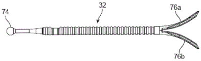
As mentioned above, the nose is a complex three-dimensional structure. It may be desirable to change its shape or better support its structure to improve or maintain its function or appearance (aesthetics), but it is difficult to change one aspect of the nose without adversely affecting another part. Indeed, previous surgical intervention is one cause of variant nasal valve function that can be treated using the systems and methods described herein. Described herein are implants, devices, systems, and method functions for altering or supporting aspects of body structure or shape, including the nose. Fig. 2A and 2B show front and side views, respectively, of an implant 32 implanted in and supporting tissue portions of a patient's nose. The implant 32 may be used to maintain or improve nasal function or appearance. The implant 32 is located beneath the skin and muscle that has been removed to better illustrate the implant and underlying nasal structure and implant. Fig. 2A-2B illustrate an implant 32 for supporting or altering the position of an internal nasal valve. The implant 32 is juxtaposed with structures in the cartilage and bone matrix layers underlying the skin and muscle. The body of implant 32 has a proximal end 34, a distal end 36, and a middle portion 38 therebetween. The middle portion 38 is located between the nasal cartilage and the patient's skin or muscle. The medial portion 38 is juxtaposed with the superior lateral cartilage 11 and the inferior lateral foot 16 of the inferior lateral cartilage. As discussed above, together with the septal cartilage, the trailing end of the upper lateral cartilage defines the internal valve angle, and the mid-portion 38 of the implant 32 is also juxtaposed with the trailing end 48 of the upper lateral cartilage 11 and thus covers or acts upon the internal valve wall, thereby providing support or altering the shape of the internal valve. The distal end 36 of the implant 32 is juxtaposed with structures in the upper portion of the cartilage and bone skeleton. In these examples, as shown in fig. 2A-2B, the distal end 36 of the implant 32 bifurcates into a first arm 40 and a second arm 42, forming the prongs of a fork. Each arm has a proximal end fixed to the implant body and a distal end not fixed to the body. In this example, the arms are juxtaposed with the nasal bone 4a, the frontal process 6 of the maxilla, and the maxillary nasal suture 7 (maxillary suture). In some variations, the distal end of the implant may be juxtaposed or adjacent to one of the plurality of structures in the upper layer or any structure or tissue in the middle or lower cartilage and skeletal framework layers (e.g., the accessory cartilage, greater alar cartilage, lesser alar cartilage, septal cartilage, maxilla, etc.).
Disclosed herein are delivery tools for delivering the implant constructs disclosed herein to a target location within a patient. Examples of delivery tools include nasal implant delivery tools.
Other examples of nasal implants and delivery tools are disclosed in U.S. patent application No.62/042,209, filed on 26/8/2014 and U.S. patent application No.14/836,841, filed on 2/8/2015, the respective disclosures of which are incorporated herein by reference in their entireties. Any of the nasal implants disclosed in U.S. patent application No.62/042,209 and U.S. patent application No.14/836,841 may be used with the delivery tool disclosed herein.
The delivery tool may include a handle including an implant loading chamber adapted to receive a nasal implant, a needle extending distally from the handle, the needle having a lumen with a portion having a non-circular cross-section, the needle having a sharpened distal end, and an actuator adapted to move the nasal implant along the needle lumen and out of an opening at the distal end of the needle.
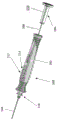
Fig. 5 shows an implant delivery device 100 for placing an implant into body tissue. The delivery tool 100 includes a handle 102, a needle 104 having a needle lumen, and an actuator 106 including a push rod 108 and a plunger assembly 110. Handle 102 includes an implant loading chamber 112 adapted to receive a nasal implant.
Fig. 6 shows a cross-sectional view of the tool 100. The implant loading chamber 112 is in communication with the needle lumen 124 and is adapted to load a nasal implant into the needle lumen 124. For example, implant loading chamber 112 may be adapted to transition the nasal implant from the deployed configuration to the delivery configuration as the nasal implant is advanced from implant loading chamber 112 into needle lumen 124. Needle lumen 124 may have a substantially smooth inner surface to facilitate delivery of the implant and withdrawal/retraction of the needle lumen relative to the implant after the implant has been delivered to the target location of the patient.
The implant loading chamber 112 may be in communication with an implant engagement surface 120 disposed between the needle lumen 124 and the implant loading chamber 112. The implant engagement surface 120 can be adapted to engage the first and second arms of the implant 32 to transition the implant from the deployed configuration to the delivery configuration. In some embodiments, the implant engaging surface comprises a substantially smooth inner surface. The smooth inner surface may reduce the likelihood of a portion of the implant catching on the implant engaging surface as the implant is advanced toward the needle lumen.
The handle 102 includes an implant orientation indicator 116 configured to provide a visual indication of a plane formed by the first and second arms of the nasal implant in a deployed configuration corresponding to the orientation of the implant within the needle lumen. The implant orientation indicator is designed so that the operator of the tool can quickly see the orientation of the tool and the corresponding orientation of the plane formed by the arms of the nasal implant in the deployed configuration. The implant orientation indicator extends from a portion of the handle such that the operator's hand does not cover or obscure the implant orientation indicator during use of the device. For example, the implant orientation indicator 116 may be positioned toward the distal end of the handle, as shown in fig. 5. The implant orientation indicator may include a first arm extending from the handle in a first direction and a second arm extending from the handle in a second direction. The first and second arms define a plane substantially similar to a plane formed by the first and second arms of the nasal implant in a deployed configuration corresponding to an orientation of the implant within the needle lumen.
In some embodiments, the delivery tool includes a push rod locking element proximate the implant loading chamber, the push rod locking element configured to prevent further proximal movement of the push rod relative to the handle. The push rod locking element may be configured to prevent the push rod from sliding out of the handle interior. Fig. 6 shows a push rod locking element 122. The illustrated push rod locking element 122 is configured to engage a notch 132 (fig. 17) on the push rod 108 to prevent further retraction of the push rod 108 relative to the handle 102.
The delivery tool actuator may include a push rod and plunger assembly. In some embodiments, the compression element may couple the push rod to the plunger assembly. A compression element 130 is shown in fig. 16 to couple the push rod 108 to the plunger assembly 110. The compression element 130 may provide additional distal axial force on the implant to prevent the implant from retracting or sliding as the tool is removed or withdrawn from the patient.
Fig. 7 shows the implant 32 placed in the implant loading chamber 112 of the implant delivery device 100. Implant loading chamber 112 is configured to receive implant 32 in a deployed configuration (e.g., with the arms of the implant open).
Fig. 8A shows the delivery tool 100 with the push rod 108 and plunger assembly 110 in a retracted position such that the implant loading chamber 112 is unobstructed by the push rod 108. Fig. 8B shows implant 32 placed within the implant loading chamber.
Fig. 9A shows the delivery tool 100 with the plunger assembly 110 and the push rod 108 advanced to push the implant from the implant loading chamber into the needle lumen. Fig. 9A shows the implant at a pre-deployment stop point, with the implant received within the needle lumen.
Fig. 9B shows ram 108 and plunger assembly 110 advanced relative to the configuration shown in fig. 9A such that the implant will be pushed distally out of needle lumen 124. Fig. 15 shows a cross-sectional view of the implant delivery device with push rod 108 and plunger assembly 110 in a distally advanced position.
Fig. 10A shows a cross-sectional view of tool 100 with ram 108 and plunger assembly 110 in a distally advanced position. Fig. 10B shows a cross-sectional view of tool 100 with ram 108 and plunger assembly 110 in a retracted position such that ram 108 is engaged with ram locking element 122 and implant loading chamber 112 is ready to be received and implanted.
Fig. 11-12 show implant 32 after being placed into implant loading chamber 112. Fig. 13 shows implant 32 within needle lumen 124. When the implant 32 is positioned within the needle lumen 124, the implant 32 is in a delivery/compression configuration. The pusher rod 108 is shown advancing the implant 32 distally through the needle lumen 124. Fig. 14 shows the implant 32 as the implant 32 extends distally past the distal end of the needle 104. As the implant 32 exits the needle lumen 124, the arms 78a, 78b of the implant 32 may transition to the deployed configuration.
Fig. 16 is an enlarged view of actuator 106 showing push rod 108 engaged with plunger assembly 110 via compression element 130. When the pusher rod begins to be retracted after deployment of the implant in the body tissue, the compression element 130 can provide a distal axial force on the pusher rod 108 to reduce the likelihood of migration of the implant from the deployed position and location.
Fig. 17 is an enlarged view of a portion of the handle 102 showing the push rod 108 engaged with the push rod locking element 122. The push rod locking element 122 may engage the push rod 108 at the notch 132 to prevent further retraction of the push rod 108 relative to the handle 102.
The delivery tool can be adapted for use with a variety of implant sizes and shapes. For example, the delivery tool can be adjusted to accommodate implants having different lengths and configurations. The implant loading chamber can be adjusted to allow different implant sizes and shapes to pass within the handle of the delivery tool. One or more components of the delivery tool can be adjusted between multiple positions to accommodate different implant lengths. In one example, the needle may be movable relative to the handle. The needle is movable relative to the handle between a plurality of discrete positions. The plurality of discrete locations may correspond to a length of the nasal implant. For example, for shorter implants, the needle may be retracted proximally to effectively shorten the length of the needle extending outwardly from the handle. In one example, the needle slider actuator is configured to move the needle between a plurality of discrete positions relative to the handle. Fig. 20 shows an implant delivery device handle 230 with a needle slider actuator 232. The needle slider actuator 232 can slide the needle 234 axially between a plurality of positions to accommodate the implant length. In some cases, the slider may also move the implant engagement surface 236 and the needle 234.
In another example, the actuator can be adjusted relative to the tool to accommodate different implant lengths. For example, the length of the actuator may be adjustable between a first position and a second position. The length of the push rod and plunger assembly may be adjusted between the first position and the second position by engaging the push rod with a first locking surface on the plunger assembly and a second locking surface on the plunger assembly. Fig. 18A-18B illustrate the actuator 200 in two discrete positions. The push rod 202 may be engaged with the plunger assembly 204 at two different positions 206, 208. The plunger assembly 204 knob 205 may be turned and then slid between two positions 206, 208. The plunger assembly 204 may be locked or engaged such that the length of the push rod 202 and plunger assembly 204 is locked during use. Fig. 19 shows an alternative configuration of the actuator 220 in which a torsion spring 222 is used to secure the plunger assembly 224 between discrete positions 226, 228.
In some embodiments, the delivery tool may be adapted to receive a cartridge containing one or more nasal implants in the implant loading chamber. The implant loading chamber may be adapted to receive a cartridge containing a nasal implant. Fig. 21 shows an implant delivery device 240 having a handle 241 and a magazine or cassette 242 containing an implant 244. The cartridge or cassette 242 may include one or more nasal implants 244. The handle 241 may be configured to receive the cartridge 242 such that the nasal implant 244 may be advanced from the cartridge 242 to the needle lumen by a push rod. In some cases, the cartridge 242 may be configured to receive two or more nasal implants.
The cartridge may be adapted to communicate with the needle lumen. The implant may enter the needle lumen directly from within the cartridge. In some cases, the delivery device may include an implant engaging surface disposed between the cartridge and the needle lumen. The cartridge may further include an implant engagement ramp adapted to engage the first and second arms of the implant to transition the implant between the deployed configuration and the delivery configuration. For example, the implant engagement ramp may urge the first and second arms of the implant into a compressed configuration such that the implant may be advanced from the implant engagement ramp into the needle lumen.
In some embodiments, the handle may be adapted to receive the cartridge such that the cartridge engages the needle to adjust the length of the needle relative to the handle. The delivery tool may be adapted to receive different cartridge sizes containing different implant sizes. The cartridge may be sized to engage the handle such that the length of the needle lumen is adjusted to work with a nasal implant contained within the cartridge. In another alternative, the cartridge may be configured to adjust the relative distance between the actuator and the needle lumen by adjusting the actuator length.
The delivery tool may include an indicator configured to provide a signal regarding the status of the implant or the delivery tool. In some embodiments, the needle comprises substantially band-like indicia at various locations along the needle.
In some embodiments, the needle of the delivery tool includes a low friction coating on the outer surface of the needle. In some cases, it may be difficult to penetrate portions of nasal tissue. A low friction coating may be used to improve needle penetration and movement of the portion relative to the nasal tissue. The low friction coating can reduce drag between the tissue and the needle during insertion and retraction of the needle in the body tissue. Typically, the low friction coating may be made of a biocompatible and lubricious material that can adhere to the needle. Examples of materials that can be used for the low friction coating include: PTFE, silicone, and poly (p-xylene) -based polymers. One example of a suitable poly (p-xylene) -based polymer may be obtained from the trade name paryleneTMIs obtained by the following steps.
The delivery tool may include an actuator aligner adapted to indicate a position of the actuator when the nasal implant is distal to the needle lumen. The actuator aligner may include markings on the actuator or on the handle. The actuator aligner may be adapted to indicate a position of the actuator when at least the distal portion of the implant has been removed from the needle lumen.
In some embodiments, the actuator aligner is a stop element that prevents continued movement of the actuator. Figures 22A-22E illustrate portions of an actuator for implant delivery devices of various configurations. Fig. 22A shows the plunger 300 prior to insertion of the delivery tool 302. The delivery tool 302 includes a trailing sheath 304. The plunger 300 is received in the delivery tool 302 and engages the trailing sheath 304. The delivery tool 302 includes a stop 306, the stop 306 preventing advancement of the plunger 300 when the delivery tool 302 is in the implant loading mode shown in fig. 22B. Fig. 22B shows plunger 300 in a first configuration relative to tail sheath 304, with a stop 306 to allow for loading of an implant. The plunger 300 may stop against a natural spring (fig. 22C) or other stop. The plunger 300 can be rotated or twisted (or the trailing sheath 304 can be adjusted) to transition from the loading mode (fig. 22B-22C) to the deployment mode (fig. 22D-22E). When twisted into the deployed mode, the spring feature or stop may be moved or forced open by a feature 308 on the handle or other portion of the device to allow the plunger 300 to advance past the stop 306. In the deployment mode, the plunger 300 may be further advanced to deploy the implant.
In some embodiments, the delivery tool may include a snap feature or mating recess. Moving or snapping the snap feature into the mating recess may produce an audible "click," "rattle," or other sound. The snap features may be locked or held in connection with the mating recess. The mating features may move into the mating recesses when the implant is in a particular position in the delivery tool, or when the implant is partially or fully deployed. Some examples include the step of indicating a position (e.g., a distal position, a deployed position) of the implant with an indicator, and so forth. The mating feature may be removed or unlocked from the handle, for example, by manually pressing a snap feature in a socket of the handle. This may be useful, for example, to release the plunger and reload additional (second, third, etc.) into the delivery tool. The indicator may provide a signal that the implant is loaded (in place in the delivery tool), that the portion of the implant has been removed from the needle (e.g., that a distal portion of the implant has been removed from the needle), or that the entire implant may be removed from the needle. The signal may be, for example, an audio signal (e.g., a beep, buzz, sound, etc.); tactile signals (such as vibration signals), visual signals (such as colored or white light, flashing lights or longer duration light signals), etc.
In some examples, the distal end of the needle may be sharp enough to pierce nasal or facial tissue, such as any of the portions described herein. The sharp distal end may minimize nasal tearing. The needle may be of any size, such as the size of a hypodermic needle known in the art; for example, the outer diameter is 8, 10, 12, 14, 16, 18, 20, etc. The needle may be sized to fit between the mucosa, epithelium, muscle skin and cartilage or bone of the nose and face. In some examples, the needle may fit between the mucosa/skin and cartilage of the nose. The needle may be long enough to place the implant through tissue (e.g., at least 50mm, at least 75mm, at least 100mm, at least 115mm, at least 125mm, or at least 150 mm). The distal end of the needle may include an opening adapted to fit the implant into the interior. The needle has a cavity adapted to receive or retain an implant. The cavity may have any cross-sectional profile such as circular, non-circular, elliptical or oval, elliptical, triangular, square, rectangular, hexagonal, etc. In some variations, different regions of the cavity may have different cross-sectional profiles. The cavity having the non-circular cross-section may be oriented relative to the handle of the delivery tool, which may control the orientation of the cavity (and the implant oriented in the cavity). The handle may control the orientation of the implant during implant delivery. The cavity may have 1, 2 or 2,3, 4, 5 or more than 2,3, 4 or 5 different cross-sectional profiles. For example, the proximal portion may be circular and the distal portion may be non-circular. In some examples, the proximal lumen region may be circular, the middle lumen region may be non-circular (e.g., elliptical, oval, ellipsoid, or any other shape including those described above), and the distal lumen region may be circular. A cavity having a non-circular cross-section may have a major axis and a minor axis. The implant may be configured to engage or may engage with a lumen of a needle or a lumen of a handle. An implant disposed in the handle lumen or the needle lumen may have first and second arms at a distal end of the implant, the first and second arms each may have a proximal end secured to the implant and a distal end unsecured to the implant, the distal end of each arm may be biased away from a central longitudinal axis of the implant, transitioning from a delivery configuration within the needle lumen toward a deployed configuration outside the needle lumen, the first and second arms each including a bevel (e.g., an outer bevel) that engages an inner surface of the needle lumen on an opposite end of the long axis. Some examples include maintaining a known orientation between the implant and the cavity (needle) during the insertion step.
The guide may provide guidance for the implant, but typically provides guidance for the actuator. The guide and the actuator may have complementary shapes. For example, the guide may be a slot and the actuator may be a rod that fits partially within the slot. Typically, a portion of the actuator will be located above the guide when in place in the guide, such that the actuator can act on (move) the implant through the delivery tool.
The actuator may include one or more markers. The indicia may indicate the position of the actuator relative to the delivery tool or implant. For example, the marker may be configured to indicate that the implant is in a desired position for deployment of the implant in tissue, that the distal end of the implant is at the distal end of the delivery tool, that the implant is in a partially deployed position, that the implant is fully delivered (deployed) into tissue, and so on. The indicia may be used to indicate that the implant is in a position, in a position ready for deployment (pre-deployment position), partially deployed, or fully deployed. For example, the indicia may indicate when the arms (prongs) of the implant are deployed and expanded, and the remainder of the implant is in the delivery tool. The marker may be any type of marker, such as a line, a plurality of lines, a thick line, a protrusion, a ring, a color, a fluorescent marker, etc., as long as it provides an indication of the position of the actuator or implant (e.g., relative to the delivery tool). The delivery tool can be withdrawn from the tissue to complete deployment of the implant, e.g., to remove a non-arm receiving portion of the implant (e.g., the implant body) from the tissue, e.g., by withdrawing the needle while holding the implant and actuator in place (in the tissue). The actuator may for any reason include, for example, 1, 2,3, 4, 5, or more than 5 of the markings just described. In addition, the actuator can have different markings corresponding to different lengths of implant, and the actuator can further include a stop mechanism to stop further travel of the actuator in the delivery tool.
Also provided are systems comprising a delivery tool described herein and one or more nasal implants. Also provided are systems comprising the delivery tools described herein and cartridges containing nasal implants. The cartridge may contain two or more nasal implants. In some embodiments, the cartridge may include an implant engagement surface configured to transition the implant to a delivery configuration.
As described above, small openings in the body can be used to place implants in a minimally invasive manner to minimize pain and scarring. However, if, for example, the tissue area to be treated is larger than a small opening in the body, it may be advantageous for the implant to be larger than the small opening. In this case, the implant may be placed through the opening in a collapsed configuration and may expand during or after placement into the body. In addition, the expanded implant may exert a force on tissue during insertion (e.g., may help hold the implant in place). In some variations, the delivery tool may be configured to receive the implant in the expanded configuration, to collapse the implant so that it passes through a small opening in the body, and then to deliver the implant to the body tissue. The implant may be delivered while the implant is in the collapsed configuration. The implant may be delivered in an expanded configuration or may be expanded during delivery. The delivery tool may include a loading chamber for loading the implant in the expanded configuration into the delivery tool and one or more shaping chambers for changing the shape of the implant. The delivery tool may include an implant loading chamber in communication with the needle lumen and adapted to load a nasal implant into the needle lumen.
The loading chamber may have a generally rectangular shape, but may instead have an oval or other shape, so long as it is capable of receiving an implant (e.g., in an expanded configuration) and allowing the implant to pass through the loading chamber (e.g., by a plunger/actuator). The loading chamber may be closed at the top (with a top), but will typically be open at the top to allow insertion of the implant. The loading chamber has a base and typically has first and second side walls (sides) and proximal and distal side walls (ends), with the proximal and distal side walls being connected to the first and second side walls, respectively (e.g., at either end). The proximal wall and the distal wall may each have an opening, wherein the proximal wall opening is configured to allow the plunger/actuator to enter the loading chamber and the distal wall opening is in open communication with the needle lumen. The proximal wall of the loading chamber may have an opening configured to allow an implant or plunger of the actuator to pass therethrough. The implant may be placed (dropped) into the loading chamber from above such that the implant is located on the base of the chamber.
Shaping the implant as described using the loading chamber, the shaping chamber/implant engagement surface, and the needle may be performed instead in other ways, so long as the implant transitions from the expanded configuration to the collapsed configuration in the delivery tool. For example, the implant delivery tool may have only a loading chamber, and the loading chamber may shape the implant as described above without the use of a shaping chamber; the implant may travel directly from the loading chamber to the needle. The implant delivery tool may have a plurality of shaped chambers, and each shaped chamber may partially change the implant configuration. The forming chamber may be oval or may be rectangular, etc.
The implant may take a different shape or a different configuration when implanted (during implantation when the implant is removed from the needle and into body tissue). The implant 32 may be transitioned from the delivery configuration to the deployed configuration during implantation in tissue. The implant may be transitioned from the collapsed or compressed configuration to the expanded configuration by moving the one or more distal walls away from the central longitudinal axis of the implant. The (e.g., distal) arm of the arm may be biased to move away from the central longitudinal axis. The arms can move out of the way straight, but are typically offset from the central longitudinal axis, causing the distal ends of the arms to bend. Tissue may be trapped between the arms. The bifurcated arms may help distribute forces over a wider tissue area. In nasal tissue, tenting and distal migration may be prevented or minimized. The bifurcated arms may also hold the implant in place when the needle or delivery device is removed. The chamfer may assist in arm bifurcating. Movement of the arms through tissue may be assisted by a bevel on the radially inner surface of the distal ends of the arms. The bevel may cut through the tissue and guide the arm through the tissue. Although an implant with two arms with chamfers is shown, the implant may also have no chamfers, a single chamfer, one chamfer on each arm, two chamfers on each arm, etc., and may have 0, 1, 2,3, 4, or more arms. The implant can be advanced (pushed) into the body tissue by the actuator/plunger.
The implant in the collapsed position may be deployed directly into tissue to transition from the collapsed configuration to the delivery configuration, but may be generally oriented prior to deployment. The implant may be oriented in the handle of the delivery tool, but is typically oriented in the needle. The implant may be oriented by a non-circular lumen (in the delivery tool handle or in the needle). A non-circular lumen having a long axis and a short axis may allow the arms of the implant to diverge (slightly) in a direction outward of the long axis (and away from the central longitudinal axis), thereby orienting the implant (via the arms) in the direction of the long axis. This may occur, for example, when the plunger is moving the implant through the implant tool handle, but typically occurs when the implant is moving through the needle. In some examples, after orientation of the implant, the needle may have a circular cross-sectional area and the implant may travel through the circular cross-sectional area but retain its orientation. For example, the distance traveled through the circular cross-sectional area may be relatively short.
The implant may transition from a delivery configuration within the needle lumen to a deployed configuration outside the needle lumen. The arms may move away from each other (bifurcate) as the implant moves away from the distal end of the needle. The implant may be fully deployed before the implant tool is removed from the implant, or the implant may be partially deployed (e.g., the arms may be deployed but the remainder of the implant may be disposed inside the needle of the delivery tool, once the arms are deployed, the needle may be moved away from the implant and tissue, leaving the implant in place). In some examples, the actuator may push the implant further into the tissue (assisted by an internal bevel on the arm to move the arm through the tissue). In other examples, the actuator may hold the implant in place when the delivery tool is removed away from the implant and actuator, and then remove the actuator, leaving the implant in place in the tissue. The implant may be moved through tissue with the aid of an internal bevel that cuts the tissue and/or a biasing arm that attempts to return to its unbiased configuration. The implant can transition from the deployed configuration to the delivery configuration when the implant exits the distal end of the delivery device.
In some embodiments, advancing the implant comprises pushing the implant distally such that the first and second arms of the implant each engage tissue, thereby moving away from the central longitudinal axis of the implant. In some embodiments, advancing the implant may include retracting a portion of the delivery tool (e.g., a needle) to allow the first and second arms of the implant to self-expand such that the arms move away from the central longitudinal axis of the implant. In some cases, the advancing may include a combination of pushing and retracting. For example, advancing the implant can include pushing the implant distally and retracting a portion of the delivery tool such that the first and second arms each engage tissue to move away from the central longitudinal axis of the implant. The first and second arms of the implant may each form an incision tract when the implant is engaged with tissue. For example, advancing the implant can include forming a first arm of a first arm incision path, wherein the first arm incision path has a longitudinal axis that is offset from a longitudinal axis of the delivery tool. The advancing may further include forming a second arm of a second arm cut-out path, wherein the second arm cut-out path has a longitudinal axis that is also offset from the longitudinal axis of the delivery tool. The longitudinal axis formed by the first arm incision path and the second arm incision path may comprise a curved or arcuate shape. The first arm cutout path and the second arm cutout path may form an angle of less than 180 degrees. The advancing implant may further include a first arm and a second arm, each arm engaging a portion of tissue located between the first arm and the second arm.
Methods of delivering the implants disclosed herein using the delivery tool are also provided. A method for supporting a tissue portion of a nose of a patient may include inserting a needle of a delivery tool into tissue of the nose. The delivery tool may include a handle portion with a needle extending distally therefrom. The needle may include a needle lumen. The handle may include an implant loading chamber adapted to receive an implant. The delivery tool may further include an actuator adapted to move the implant along the needle lumen and out of the opening at the distal end of the needle. The method may include advancing the implant distally from the needle lumen to place a distal end of the implant within the nasal tissue. The implant may include a first arm at a distal end of the implant and a second arm at a distal end of the implant. Distally advancing the implant may include a first arm that moves away from a central longitudinal axis of the implant and a second arm that moves away from the central longitudinal axis of the implant during the advancing step. The method may include withdrawing the delivery tool to dispose a central portion of the implant within the nasal tissue and supporting the tissue portion with the implant.
Advancing the implant may include pushing the implant distally such that the first and second arms each engage tissue to move away from a central longitudinal axis of the implant.
The method may include loading an implant into an implant loading chamber of a delivery tool. The method may include loading an implant into the implant loading chamber using forceps. The method may include loading a cassette containing the implant into the implant loading chamber.
The method may include retracting the pusher bar of the actuator to a proximal locking point prior to loading the implant in the implant loading chamber.
The method may include adjusting a length of a needle extending from the handle prior to loading the implant. The method may include sliding the needle relative to the handle by moving a slider coupled to the handle of the needle to move the needle between a plurality of discrete positions relative to the handle. The method may include adjusting the length of the push rod and plunger assembly prior to loading the implant.
The method may include advancing the implant from the implant loading chamber into the needle lumen. The delivery tool may include an implant engagement surface disposed between the needle lumen and the implant loading chamber, with the method including advancing the implant from the implant loading chamber through the implant engagement surface and into the needle lumen. The loading step may include loading the implant into the proximal end of the needle and advancing the implant to the distal end of the needle prior to the inserting step. The loading step may include collapsing the first and second arms of the implant prior to entering the proximal end of the needle.
The method may include advancing the actuator to a locking point, then unlocking the actuator prior to advancing the implant distally from the needle lumen to place the distal end of the implant within the nasal tissue.
The inserting step may include inserting the distal end of the needle into tissue of the nose. The method may further include maintaining a known orientation between the implant and the needle during the inserting step. Maintaining a known orientation between the implant and the needle may include engaging the implant with a portion of the needle lumen having a non-circular cross-section.
The method may include continuing to provide a distal axial force on the implant with the pusher bar and the compression element while beginning to withdraw the delivery tool.
When in place in body tissue, such as nasal tissue or any other type of tissue in the body, bone or other structures may provide cantilever support for the implant. For example, extending an implant for supporting a nasal valve beyond the edge of the maxilla may provide cantilever support. The implant 32 may utilize one or more forces between different portions of the implant to provide a force to alter or support tissue that needs to be altered or supported. The implant 32 may utilize forces from one or more underlying structures (e.g., a bone structure such as the maxilla or nasal bone, an appendage, upper or lower cartilage) to support a structure in need of support (e.g., an appendage, upper cartilage, or lower cartilage such as the tail region of the upper lateral cartilage). The connection of the upper and lower cartilage will support or strengthen the nasal valve and improve the nasal appearance or breathing or reduce snoring or other problems. As described above, the upper and lower lateral cartilages 11 and 16 interface with the nasal valve along with the septum and inferior turbinate. The implant 32 functions to support or alter the nasal valve. In certain examples, the implant may utilize force to alter or support the caudal (inferior) region of the upper lateral cartilage, thereby altering or supporting the internal nasal valve and the internal valve angle. In response, the valve angle may increase, decrease, or may remain constant, but will typically remain constant or increase. Although the overlying skin and nasal tissue have been removed in this figure, they may provide force and may hold the implant against underlying tissue at any location along its length, such as on the maxilla or nasal bone or over its entire length. The nasal bone 4 may exert a force on the implant 32. The implant may behave as a lever to provide support to the structure. Structures such as bone (e.g., nasal or facial bone), cartilage, or other bodily structures may exert forces on the implant to provide support along the length of the implant and to the bodily structures (e.g., nasal valve). For example, the nose or maxilla may provide force to the superior lateral cartilage 8 and the inferior lateral cartilage 16.
In some variations, the implant is a biocompatible implant for nasal valve repair. The implant may be used to reinforce a nasal valve in a nose of a patient. The implant may support the cartilage and help resist or reduce movement of the cartilage during inhalation of air, thereby keeping the patient's airway open. Although the implant 32 of fig. 2A-2B is juxtaposed or in proximity to a particular structure in the cartilage and skeletal framework layers of the patient's nose and overlying muscle/skin, the entire implant or one or more regions of the implant may be juxtaposed or placed in proximity to any (body) cavity, structure or tissue within the patient's body. For example, a protrusion (arm) or other protrusion, or a portion of an arm or other protrusion, a central region, a portion of a central region, a distal end, a proximal end, a strain relief portion, a feature, a ridge, etc., may be juxtaposed or placed in proximity to any (body) cavity, structure, or tissue within the patient. In some variations, the implant or region of the implant may be juxtaposed or placed proximate to one or more of any cavity, structure or tissue, such as facial or nasal bone, cartilage, connective tissue, fascia, fat, respiratory epithelium, squamous epithelium of the nasal cavity, ligaments, muscle, mucus, skin, (winged) fibrofatty tissue, blood vessels, mucosa, nasal mucosa, frontal bone, tear bone, maxilla (e.g., anterior bone, prefrontal process), nasal bone, moldboard, maxillary sutures, prefrontal sutures, paranasal cartilage, upper outer cartilage (including central regions of cranial borders, caudal borders, or upper outer cartilage), lower outer cartilage, greater alar cartilage (e.g., lateral foot, medial foot), secondary cartilage, septal cartilage (e.g., lateral process, septal cartilage), and the like. The implants may be juxtaposed or adjacent to one or more other implants or composite structures. An implant juxtaposed to or in proximity to a (body) cavity, structure or tissue may act on it (e.g., support it, exert a force on or against it, act as a fulcrum for a force from it, etc.) or not. For example, a portion of the implant may span tissue without substantial interaction or influence on the tissue. The implant is placed over or under one or more of the above-mentioned tissues. The implant may be placed in any orientation relative to these tissues, and may be placed substantially parallel, perpendicular, or oblique to the long or short axis of the cavity, structure, tissue, or another implant. In some examples, the implant is placed within nasal tissue. In some embodiments, the implant is located partially within the nasal tissue and partially within the surrounding tissue (e.g., the maxilla). The implant may be attached (e.g., with an adhesive, suture, screw, etc.) to a structure, tissue, or another implant (e.g., those described herein) or may be proximate to or in contact with a structure, tissue, or another implant (e.g., those described herein). The implant may be placed such that the proximal end of the implant is sufficiently clear of the nostril rim for insertion through mucosal tissue. The implant may be held in place by a force (such as a compressive force) between the implant and the structure, tissue, or another implant. The implant may be held in place (at least partially) by forces on the implant from the upper layer. In some particular examples, the distal end of the nasal implant is held (at least partially held) in place against the maxilla and/or nasal bone sutures by the overlying skin and muscles pressing the implant (snuggly) against the bone or sutures.
Fig. 3A shows an implant for acting on body tissue, the implant having a generally longitudinal body with a first end 70, a second end 72, and a middle portion disposed between the first and second ends. The implant defines a central longitudinal axis 71. In some examples, the first end of the implant is located at a position proximal to the insertion position in the tissue. The second (or distal) end 70 of the implant 32 has a first arm 76a and a second arm 76b, each having a proximal end fixed to the body and a distal end not fixed to the body.
In some variations, the implant is adapted to have or assume a different configuration. For example, the implant may have a collapsed configuration and an expanded configuration. The implant may be capable of assuming a (continuous) series of configurations between the contracted and expanded configurations. In some cases, the implant may be capable of remaining in any of these configurations. The collapsed configuration may be a delivery configuration and may be used to deliver the implant, for example, moving the implant through an implant delivery device and placing it into body tissue. The collapsed implant may be small enough to easily fit into a relatively small delivery device. The implant in the expanded configuration may be in a deployed configuration and may be used, for example, to retain the implant in body tissue once the implant is in place in the body. The expanded configuration may also or alternatively assist in the bio-absorption of the bio-absorbable implant, such as by providing the implant with an access path for bodily fluids involved in bio-absorption. For example, a series of configurations between the delivery and deployment configurations can help guide the implant to the desired location during deployment.
In some variations, the arms of the implant may be adapted to move relative to the implant body. The arm may be adapted to move away from, about or towards the central axis of the implant body. The arm or a portion of the arm may comprise a material adapted to move the arm from the first position to the second position. The material of the moving arm may be, for example, an elastically deformable material or a shape memory material. The arm may be biased to move to the second position.
The two or more arms may be adapted such that they can be moved (e.g., pushed or pulled) toward or away from each other without breaking or breaking. The arms can be sufficiently flexible (e.g., deformable, flexible, etc.) to move up to 10 °,20 °, 30 °, 40 °, 45 °, 50 °, 60 °, 70 °, 80 °, 90 °, 145 °, or 180 ° relative to the central longitudinal axis of the implant body from the first position to the second position without breaking or fracturing, or can move between any of these ranges (e.g., from 30 ° to 70 °, from 10 ° to 50 °, etc.). In some examples, the arms in a first position on the implant may be oriented parallel (or nearly parallel) to the central longitudinal axis of the implant, and then may be moved to a second position such that the arms are oriented obliquely (e.g., up to 10 °,20 °, etc., as described above) relative to their first position and the central axis of the implant body.
In some examples, the implant has a first arm and a second arm, and the distal ends of the arms are adapted to move away from a central longitudinal axis of the body. The first and second arms may transition from the delivery configuration toward the deployed configuration or from the collapsed configuration toward the deployed configuration. In some examples, the first and second arms are biased toward their deployed configuration. In some examples, the biasing arms can transition from the delivery configuration toward the deployed configuration when the force from the delivery device is removed, such as by removing the implant from the device.
The arms on an implant, such as first and second arms 76a and 76b, may have different shapes or different configurations, or they may have the same shape or the same configuration. The arms may be mirror images of each other. Instead of or in addition to the distal arms, the distal end may have protrusions. The arms or protrusions may be used to perform an implant or implant arm function, they may work independently of each other, or work with another, or other, structure to perform the function. Such functions may include, for example, guiding the implant into a delivery tool, orienting the implant in the delivery tool, orienting the implant relative to an actuator (pusher), delivery tool, or patient tissue, retaining the implant in the delivery tool, orienting the implant relative to the patient, cutting or passing an arm through the patient tissue, compressing or moving the patient tissue, retaining the implant in the patient tissue, applying a force on the patient tissue, and so forth. The arms or projections may be or have barbs, ridges, cilia or cilia, generally elongated rods, hair, hooks, loops, prongs, rods, spikes, threads, teeth, and the like. The arms or projections may be stiffer or may be more flexible. The arms or protrusions may be more flexible or rigid than the rest or all of the implant. The arm or protrusion may exert a force on another portion of the implant, another implant, or body tissue. The arm or protrusion may provide or cause friction (e.g., stiction) between the arm or protrusion and another portion of the implant, on another implant or on body tissue. The implant may have one or more arms, protrusions or protuberances, e.g., 2,3, 4, 5, 6, more than 10, more than 20, more than 100, more than 1000, etc. The arms or protrusions may be more flexible in a first dimension (e.g., in depth) or more flexible or inflexible in a second axis (e.g., along the width or from side to side or along the length) when extending away from the central longitudinal axis of the implant. The arms can be configured to be pulled or pushed inwardly (e.g., toward the central longitudinal axis of the implant) and can be pushed or extended outwardly (e.g., away from the central longitudinal axis of the implant).
Fig. 3A-3B also show first and second arms 76a, 76B, the first and second arms 76a, 76B having first and second arm inner ramps 80a, 80B, respectively, on a radially inner surface of the distal end 72 of the implant 32. A bevel (e.g., a bevel that intersects another bevel at any angle other than 90 °), particularly an inner bevel, may be used, for example, to guide an implant or an implant arm through body tissue. The first arm inner chamfer 80a has a first sharp edge 81a and the second arm inner chamfer 80b has a second sharp edge 81 b. The tip of the inner bevel may be particularly useful for cutting through tissue during implant deployment to provide a path within the body tissue for the travel of the implant arms. For example, the tip of the inner bevel may cut or move through tissue without causing undue tearing or excessive damage, in some examples an implant having a body and an arm, the arm having a cross-sectional area that is less than the cross-sectional area of the body. In general, a small sharp cut through tissue causes less pain and heals better than tissue that is torn or subjected to a larger cut. As described in more detail below, the tip of the bevel may cut through tissue, and during implant deployment, the beveled end of the bevel and the rest of the arm may follow the tip as it moves through the tissue. The incision, slice, or path through tissue on the distal end may have a smaller cross-sectional area than the tissue contacting portion of the implant body or implant delivery device. Because the ramp serves to guide the arm through the tissue in front of the delivery device, and the arm is smaller than the distal end of the delivery device containing the implant: the cut made by the bevel and the insertion path formed by the bevel and the arm may in some cases need only be so large that the arm can pass through it; it need not be large enough to move the delivery device or implant through. An implant having flexible or otherwise movable arms (e.g., relative to the implant body) can be pushed or otherwise advanced through body tissue during implant deployment, and the faces (or angled portions) of the internal ramps can push against the body tissue, forcing the arms away from the central longitudinal axis of the implant body (and toward the deployed configuration). Alternatively or additionally, the implant arms may be biased toward the deployed configuration, and the ramp may help transition the biased implant arms toward the deployed configuration and the deployed implant position in the body tissue.
Fig. 3A also shows first or second arms 76a, 76b, each first or second arm 76a, 76b having first and second arm outer ramps 78a, 78b, respectively, on a radially outward surface of distal end 72 on implant 32. The outer bevel may be used, for example, to guide the implant into a delivery device, to collapse the implant into a collapsed configuration, to orient the implant in the delivery device, to guide the implant through the delivery device, and the like. The inner and outer ramps 80a, 78a on the first arm 76a form a double ramp: the bevels or inclined surfaces may share an edge (e.g., two inclined surfaces meet at any angle other than 90 °), or may be separated from each other. In some examples, the first and second or inner and outer bevels or inclined surfaces intersect at any angle other than 90 ° but do not share an edge (e.g., bevel shape from a different edge). The implant or arm or protrusion may have one or more beveled or sloped surfaces or edges that intersect one another at any angle other than 90 degrees. The ramp may be at the end of the arm or projection or along one side of the projection or projection.
Fig. 23A-23B show views of a molded implant 1800 having beveled ends with a retaining element 1802 used in manufacture. After forming the device, cuts can be made along lines 1804 and 1806, respectively, to form the beveled ends of arms 1808 and 1810, such as the 63 degree trim angle shown.
FIGS. 24A-24C show views of a molded implant having beveled ends. As shown, the overall length of the device 1900 may be in the range of 0.74 inches to 1.04 inches. The arms 1902 and 1904 are statically deployed at their ends at 0.166 inches to 0.206 inches. These figures illustrate the dimensions of an implant that may be used with the present invention, as discussed in more detail above. Detail a of fig. 24C shows arms 1902 and 1904 intersecting at point 1906. Arms 1902 and 1904 intersect at a point 1906 to form an angle. The angle shown in fig. 24C is an acute angle of less than 90 °. In some embodiments, the arms 1902 and 1904 may engage tissue such that the arms 1902, 1904 form an angle of less than 90 °. In some embodiments, the angle between the arms 1902, 1904 is less than 180 ° when the implant is implanted in tissue.
The implant may also include one or more barbs, forked features, or flared features on the proximal end of the implant. Prongs, barbs or expansion features at the proximal end of the implant may prevent the implant from moving back out of the insertion point. Fig. 25 shows an implant 432 having a proximal end that can be opened after exiting the needle to prevent the implant from moving after the delivery tool/needle is deployed and retracted. Implant 432 has a proximal feature 474 at a proximal end. As shown, the proximal feature 474 is a blunt end. Implant 432 has a second (or distal) end with a first arm 476a and a second arm 476b, each arm having a proximal end fixed to the body and a distal end not fixed to the body. First and second arms 476a and 476b may have one or more outer ramps 478a and 478b, respectively, on a radially outward surface of the distal end of the implant. The outer ramps 478a, 478b may engage each arm 476a, 476b, respectively, with the surrounding tissue. Implant 432 also has a strain relief portion 482. As shown, the strain relief portion 482 has a relatively smaller cross-sectional area (e.g., diameter) than another portion of the implant. Implant 432 shows proximal feature 474 in a compressed or unexpanded configuration and an expanded configuration. In the expanded configuration, the proximal features are expanded by the barbs/ arms 474a, 474 b. The proximal barbs, forked features, or flared features may be smaller than the distal arms (476a, 476b) because they are sized to prevent migration or movement of the implant relative to the tissue surrounding and adjacent to the proximal end of the implant.
The implants disclosed herein can include a variety of materials to tailor the stiffness, external stiffness/softness, biocompatibility, and absorption profile of the implant. In some embodiments, the implant may include an inner structure that is degradable with a hydrophobic outer coating. Degradable materials can be degraded in vivo by hydrolysis. Degradation can be slowed by coating the degradable material (e.g., hydrophobic coating) with a coating to control or modulate the degradation of the implant. The hydrophobic coating may delay the entry of water and subsequently the hydrolysis of the degradable portion of the implant. One example of a hydrophobic material that may be used is polycaprolactone, which is an absorbable material that is hydrophobic, crystalline, and highly elastic, making it well suited for coatings. The coating may be applied with a specially selected solvent mixture to minimize the pairThe influence of the following polymer structure. In some embodiments, a non-absorbable biocompatible coating may be used, such as silicone, epoxy acrylate, or ParyleneTMTo slow the absorption of water into the underlying polymer.
The rate, distribution and/or period of biodegradation of the implant can be adjusted. For example, a variety of absorbable and non-absorbable coatings may be applied to the underlying implant structure that already exhibits the mechanical properties required to support the upper and lower lateral nasal cartilage. There are many possible coatings including polycaprolactone, silicone, fluoropolymers, vinyl alcohol, acrylates, and the like. In some embodiments, the coating may be ParyleneTM. Exemplary hydrophobic coating compound ParyleneTM(poly (dichloro-p-xylene)) has the following form:

ParyleneTMn is a basic member of the family, usually most permeable to humidity. ParyleneTMC and D are commonly used for moisture resistance. Due to the typical pinhole-free coating properties, ParyleneTMHave been used primarily as a complete moisture barrier for electronic and medical implants. In some cases, ParyleneTMCan be used as a controlled release agent for drugs released from materials underlying the coating. For example, the drug may be located in ParyleneTMIn a layer or material underlying the coating. In other forms of coating, ParyleneTMIt may also be used to add lubricious coatings on guidewires and catheters. In this disclosure, ParyleneTMIs used differently from conventional applications. In one embodiment, the semi-permeable nature of very thin coatings may be advantageously used to control the ingress of water through the thin coating and into contact with the underlying implant structure. The rate of biodegradation of the implant can be controlled by selecting and controlling the thickness and conformability of the coating, e.g., ParyleneTMAnd (4) coating.
ParyleneTMHas been well established and allows for conformable coating processesThe thickness of the coating on the implant substrate is controlled. In order to promote some passage through ParyleneTMThe water transport of the coating and initiation of hydrolytic degradation, the implant can be coated at a thickness in the range of about 0.1 to about 10 microns, preferably 0.1 to 5 microns to allow for a semi-permeable design. The design of the semi-permeable coating allows for selective adjustment of the absorption rate of the implant, with the degree of permeation being determined by the coating thickness and conformability.
The thickness of the hydrophobic coating can be selected to alter the absorption profile of the implant. In some embodiments, the hydrophobic coating may have a thickness of from about 0.1 microns to about 10 microns. In some embodiments, the hydrophobic coating may have a thickness of from about 0.1 microns to about 5 microns. In some embodiments, the hydrophobic coating may have a thickness of from about 0.1 microns to about 1 micron. In some embodiments, the hydrophobic coating has a thickness of less than 10 microns. In some embodiments, the hydrophobic coating has a thickness of less than 5 microns. In some embodiments, the hydrophobic coating has a thickness of less than 1 micron. The thickness of the coating can be selected to control the rate of water entry through the coating into the implant core.
The hydrophobic coating may be applied to the entire outer surface of the implant or to portions of the outer surface of the implant. In some embodiments, a hydrophobic coating is applied to a central rod portion of the implant. In another embodiment, a hydrophobic coating is applied to the portion of the implant other than the ends. For example, the proximal or distal ends may be uncoated to serve as sites for water entry.
The conformability of the hydrophobic coating can also be selected to alter the absorption profile of the implant. In some embodiments, the conformability of the hydrophobic coating is selected to control the rate at which water enters the implant core through the hydrophobic coating. In some embodiments, the hydrophobic coating has a pattern conformity with the coated portions and the open portions. The patterned hydrophobic coating may be applied over the entire outer surface of the implant or over portions of the implant. In some embodiments, the hydrophobic coating may have a porous structure.
In some embodiments, the hydrophobic coating may have a laminate structure made of multiple materials. For example, in some embodiments, a combination of bioabsorbable and non-bioabsorbable layers may be used to modulate the degradation rate or profile of the implant after implantation into nasal tissue.
The coating may be applied using various processes, such as vapor deposition, dipping, spraying, sputter coating, brushing, and the like.
In some embodiments, the hydrophobic coating is bioabsorbable. In the case of polycaprolactone, the coating itself is hydrophobic and bioabsorbable, allowing complete absorption over time. Using a dip coating process, coating thicknesses of 0.1 to 10 microns can be achieved to achieve the desired results. Furthermore, the same effect can be achieved by depositing 0.001 to 20 wt% polycaprolactone on the implant substrate. Polycaprolactone is readily dissolved in a mixture of various solvents consisting of cycloalkane, organic ester, chloroform and other such organic solvents, but the mixture is not limited to these compositions.
The degradation profile rate can be selectively adjusted so that the lifetime of the implant core or implant base polymer substrate can be increased up to 20 times.
Fig. 26 shows examples of implant cores having different coating thicknesses. The base shows the implant core prior to exposure to accelerated physiological conditions as a control comparison to the other implant configurations shown in fig. 26. Accelerated physiological conditions include high temperature saline conditioning to accelerate the effects of moisture penetration. Accelerated physiological conditions can simulate prolonged exposure to physiological conditions. The implant core had coatings of 0.0 μ, 0.1 μ, 1.0 μ, and 10 μ. Fig. 26 shows that the thicker the coating, the lower the amount of degradation of the implant for the illustrated implant exposed to accelerated physiological conditions. The uncoated cores degraded the most, while the 10 micron coatings degraded the least. Coating thickness, conformability, and patterning can be selected to tailor the degradation of the implant under physiological conditions.
Fig. 27A-D illustrate embodiments of nasal implants having various coating configurations. Fig. 27A shows an implant 32 having a coating 500 on or over substantially the entire outer surface of the implant 32. The coating 500 may slow or prevent water ingress, thereby slowing degradation of the implant 32 after implantation into tissue. Fig. 27B shows implant 32 with coating 500 on the central longitudinal portion of the implant between lines 501 and 502. The absence of the coating 500 on the proximal and distal ends allows water to enter the implant 32 through the uncoated portion to facilitate degradation of the implant 32. Fig. 27C shows an implant 32 having a coating 500 on the outer surface of the implant including the central longitudinal portion of the implant 32 and the arms 76a, 76b of the implant. Proximal feature 74 is not covered by coating 500, allowing water to enter the implant to facilitate degradation of implant 32 by proximal feature 74. Fig. 27D shows implant 32 with a discontinuous coating 520 over or on substantially the entire outer surface of implant 32. The discontinuous coating 520 can slow or prevent water from entering the coated portion to slow degradation of the implant 32 after implantation in tissue, while allowing water to enter through the discontinuous portion to facilitate degradation of the implant 32 in the uncoated portion.
The implant, arms or protrusions may have other or additional features such as catches, prongs, teeth, etc. The features may be angled relative to the implant, arms, or protrusions such that the features hold the implant, arms, or protrusions in place in the delivery device or tissue. Features on the arms or protrusions may limit or prevent substantial proximal and/or distal movement or side-to-side (lateral) movement of the implant. Fig. 3A shows an implant 32 having multiple segments.
The implant may have one or more proximal, distal or body features as described herein or US 2011/0251634, US 2012/0109298 by Iyad Saidi, Gonzales et al; or any of the features shown in U.S. patent application No.14/192,365 filed on 27/2/2014. Fig. 3A-3B illustrate an implant 32 having a proximal feature 74 at a proximal end. As shown, the proximal feature 74 is a blunt end. The proximal features may be sharp or flat, but will typically be rounded or atraumatic. The atraumatic end may prevent the proximal end of the implant from damaging, cutting, or dislodging tissue when in place in tissue, such as nasal tissue. The proximal features may help anchor or otherwise hold the implant in place in the tissue in which it is implanted. As described in further detail below, the proximal feature may also be configured to receive or cooperate with a plunger or actuator to help orient or move the implant within or through the delivery device and implant the implant into tissue. The proximal feature and the actuator or plunger may interact in any manner that allows the actuator to move the implant. For example, the implant may have a female end and the plunger or actuator may have a male end. Implant 32 also has a strain relief portion 82. As shown, the strain relief portion 82 has a relatively smaller cross-sectional area (e.g., diameter) than another portion of the implant. The strain relief portion may be larger than the other region, but may provide strain relief by having a different configuration or a different material. The strain relief portion may be more flexible than another region of the implant or may have a lesser bending stiffness. The strain relief region may be used to accommodate movement of tissue (e.g., the nose) so that the nose may flex. An implant for nasal or facial tissue may be configured such that when the implant is in place in nasal tissue, the strain relief portion is adjacent the mucosa to accommodate movement of the nose. The strain relief portion may work with a proximal feature, such as a blunt end, to retain the implant in tissue (e.g., the tissue may form a loop around the neck and the proximal end may prevent movement through the loop).
In some variations, the implant may have a relatively low profile (e.g., short height) in at least one dimension (length, width, height). For example, the implant height may be less than 1mm, less than 2mm, less than 3mm, less than 4mm, less than 5mm, less than 10mm, less than 20mm, or any dimension therebetween, such as from 1mm to 2mm, from 1 to 5mm, from 2mm to 4mm, and so forth. A low profile implant may be particularly advantageous, for example, because it may be inserted through a small implant hole that is easy to heal, it may be of a desired shape to accommodate the anatomy of the space in which it is implanted, or it may not be visibly apparent when implanted. The implant height may be selected based on the implant environment and the desired effect of the implant. For example, in the face and nose, the underlying cartilage and bone generally determine the shape of the face and nose, although muscles and skin also play a role. The muscles, skin and related tissues that cover the underlying cartilage and bone tend to take the shape of the underlying structures they cover. The skin and muscle thickness varies from individual to individual. Some people have relatively thick skin and muscles, others have thin skin and muscles. A relatively tall implant placed over cartilage or bone may cause significant bulges or protrusions in the overlying thin muscle and skin that may be noticed by observation alone, which may be uncomfortable or unnatural to the person being observed, but may not cause significant bulges or protrusions in persons with thicker muscle and skin that better receive or conceal the implant. An implant having a relatively small height may result in a relatively low profile that is not visible through the skin when the implant is in place in the nose. In some cases, the low profile implant may form a small bump or protrusion that is detectable by close examination or palpation. The body of the implant may be curved or bent (and may have various features that are not straight), but will generally be relatively straight and capable of being bent or curved. For example, the implant may be bent to a minimum bend radius of 15mm +/-0.5 mm.
Different regions of the implant may have material properties such as strength, flexibility, rigidity, bending stiffness, etc. The material properties of the implant may be selected to approximate the material properties of the body structure. For example, the bending stiffness of a nasal implant may be the same or close to the bending stiffness of nasal tissue, such as cartilage. The elastic modulus of some nasal cartilage is measured as 5 to 32MPa, as described below. An implant, or a portion of an implant, as described herein, such as a central region, an end region, an arm region, a proximal feature, a distal feature, a protrusionThe bump or other portion of the implant may have a modulus of elasticity between 5 and 32MPa or greater than 2, 4, 5, 10, 15, 20, 25, 30, 32, 35, 40 or 50MPa or less than 2, 4, 5, 10, 15, 20, 25, 30, 32, 35, 40 or 50MPa, or any value between 2, 4, 5, 10, 15, 20, 25, 30, 32, 35, 40 or 50MPa, such as any value between 2 and 50MPa, 10 and 30MPa, etc. The bending stiffness of some lath implants formed by septal cartilage of the nose has been determined to be between 50 and 130N-mm2Or 50 to 140N-mm2The bending stiffness of the implant or parts of the implant may also be in this range. The implant bending stiffness may also be greater or less than this value. For example, other support structures in the body may provide additional support with the implant and require a lesser amount of support from the implant, or the supporting tissue may also be weaker and may require greater support from the implant. An implant, or a portion of an implant, such as a central region, end region, arm region, proximal feature, distal feature, protrusion, protuberance, or other portion, as described herein, may have a bending stiffness greater than 10, greater than 30, greater than 50, greater than 75, greater than 100, greater than 150, greater than 200, greater than 300, greater than 400 or less than 600, less than 500, less than 420, less than 400, less than 300, less than 200, less than 130, less than 100, less than 50. For example, the implant or a portion of the implant may have a thickness in the range of 10 to 590N-mm230 to 450N-mm260 to 250N-mm275 to 200N-mm250 and 130N-mm2Or 9 and 130N-mm2Bending stiffness in between. In some embodiments, the implant has a bending stiffness of less than about 130N-mm2In the middle of (a). In some embodiments, the implant has a bending stiffness of about 10 to about 130N-mm2In the middle of (a). In some embodiments, the implant has about 50 to 130N-mm2Middle of bending stiffness of (a). The material properties of the bioabsorbable implant change over time; the bioabsorbable implant is thus configured to have any material properties, such as those described above, after a period of time in the body or after exposure to bodily fluids.
The implant may be made of any biocompatible material that provides the desired support and shaping characteristics of the implant. The implant may be made partially or entirely of non-biodegradable materials known in the art, such as any polymer, metal, or shape memory material. The implant may be made of organic and/or inorganic materials. The material of the implant may be a solid (e.g., titanium, nitinol or golts), braided or woven from a single material (e.g., titanium or polyethylene terephthalate, or a combination of materials). The textile material may have pores that allow tissue ingrowth after implantation. Representative synthetic polymers include alkyl celluloses, cellulose esters, cellulose ethers, hydroxyalkyl celluloses, nitrocellulose, polyalkylene glycols, polyalkylene oxides, polyalkylene terephthalates, polyalkylene, polyamides, polyanhydrides, polycarbonates, polyesters, polyglycolides, polymers of acrylates and methacrylates, polyacrylamides, polyorthoesters, polyphe azenes, polysiloxanes, polyurethanes, polyvinyl alcohols, polyvinyl esters, polyvinyl ethers, polyvinyl halides, polyvinyl pyrrolidones, polyether ketones, silicone-based polymers, and blends and copolymers of the foregoing.
Specific examples of these broad types of polymers include poly (methyl methacrylate), poly (ethyl methacrylate), poly (butyl methacrylate), poly (isobutyl methacrylate), poly (hexyl methacrylate), poly (isodecyl methacrylate lauryl methacrylate), poly (phenyl methacrylate), poly (methyl acrylate), poly (isopropyl acrylate), poly (isobutyl acrylate), poly (octadecyl acrylate), polyethylene, polypropylene, poly (ethylene glycol), poly (ethylene oxide), poly (ethylene terephthalate), poly (vinyl alcohol), poly (vinyl acetate), poly (vinyl chloride), polystyrene, polyurethane, poly (lactic acid), poly (butyric acid), poly (valeric acid), poly [ lactide-co-polyglycolide ], (methyl methacrylate), poly (isobutyl methacrylate), poly (hexyl methacrylate), poly (isodecyl methacrylate), poly (ethylene glycol methacrylate), poly (lauryl methacrylate), poly (phenyl methacrylate), poly (methyl acrylate), poly (isopropyl acrylate), poly (isobutyl acrylate), poly (octadecyl acrylate), poly (vinyl acetate), poly (ethylene glycol), poly (ethylene oxide), poly (ethylene terephthalate), poly (ethylene glycol), poly (vinyl acetate), poly (vinyl chloride), poly (vinyl acetate), poly (lactic acid), poly (valeric acid), poly [ lactide-co-polyglycolide ], (lactide-co-glycolide), Poly (fumaric acid), poly (maleic acid), copolymers of poly (caprolactone), or copolymers of poly (lactic acid) and polyethylene glycol, and blends thereof.
The polymer used for the implant may be non-biodegradable. Examples of non-biodegradable polymers that may be used include Ethylene Vinyl Acetate (EVA), poly (meth) acrylic acid, polyamides, silicone-based polymers and copolymers, and mixtures thereof.
In some embodiments, the implant may include a combination of one or more bioabsorbable materials and non-absorbable materials. For example, in some cases, at least one of the distal end, proximal end, or middle portion is comprised of a core made using a non-absorbent material or an absorbent material. The implant may then include an outer layer made of a different non-absorbable or absorbable material than the core. In some examples, the core layer and the outer layer are fixedly laminated to each other. In other examples, the core layer and the outer layer are slidably engaged with each other.
In some embodiments, the first and second arms of the implant are configured to self-expand toward the deployed configuration. In some embodiments, the first and second arms of the implant are configured to transition to the deployed configuration by engagement with a portion of tissue or a delivery tool.
For example, the implant or an arm or feature on the implant may include a shape memory material. In some variations, the implant comprises a biocompatible, bioabsorbable material, such as a bioabsorbable polymer. Bioabsorbable or biodegradable implants can provide structure and support to body tissue, such as nasal tissue, for a temporary period of time, and can induce or cause the formation of scarring or other tissue, thereby providing structure and support to body tissue for longer periods of time (including after degeneration of the implant). A bio-formed scar or other tissue may be beneficial because it is more comfortable than an implant, provides longer-term support, better stays in place, and the like. Some or all of the implant may be degraded into small parts in the body (also known as biodegradable) and may be bioabsorbable. The implant or implant body may consist essentially of a bioabsorbable material. The implant or implant body may comprise two or more different bioabsorbable materials. If the implant comprises a bioabsorbable portion and a non-bioabsorbable portion, the methods as described herein may include biodegrading and bioabsorbable implants or only portions of implants. Bioabsorption can be promoted by tissues and organs. Bioabsorbable tissues and organs can include bodily fluids such as blood, lymph, mucus, saliva, and the like. Bacteria may also aid in the bio-absorption material. The implant may be made partially or entirely of one or more biocompatible, biodegradable materials, such as naturally occurring or synthetic polymers. Biodegradable implants can be made from poly (lactide), poly (glycolide), poly (lactide-co-glycolide), poly (lactic acid), poly (glycolic acid), poly (lactic acid-co-glycolic acid), poly (lactide)/poly (ethylene glycol) copolymer, poly (glycolide)/poly (ethylene glycol) copolymer, poly (lactide-co-glycolide)/poly (ethylene glycol) copolymer, poly (lactic acid)/poly (ethylene glycol) copolymer, poly (glycolic acid)/poly (ethylene glycol) copolymer, poly (lactic acid-co-glycolic acid)/poly (ethylene glycol) copolymer, poly (caprolactone)/poly (ethylene glycol) copolymer, poly (orthoester), poly (phosphazene), poly (hydroxybutyrate), or a copolymer comprising poly (hydroxybutyrate), Poly (lactide-co-caprolactone), polycarbonate, polyesteramide, polyamide, poly (dioxanone), poly (alkylated alkylate), copolymer of polyethylene glycol and polyorthoester, biodegradable polyurethane, poly (amino acid), polyetherester, polyacetal, polycyanoacrylate, poly (oxyethylene)/poly (oxypropylene) copolymer or blends or copolymers thereof. In some examples, the implant comprises poly-L-lactic acid (PLLA) or poly-D-lactic acid (PDLA) or both.
In some examples, the implant is a PLLA/PDLA copolymer at 90:10, 80:20, 70:30, 60:40, 50:50, or between any of these values. In some examples, the implant is 70:30, +/-10% PLLA/PDLA copolymer.
The implant may have different portions made of different bioabsorbable materials based on the desired characteristics of each portion and based on the type of tissue that each portion engages and the typical characteristics of the type of tissue. It may be desirable for the arms and middle portion of the implant to provide longer structural support than the proximal end. For example, the arms and the middle portion may be made of a first bioabsorbable material having a first bioabsorbable profile, and the proximal end may be made of a second bioabsorbable material having a second bioabsorbable profile. The second bioabsorption profile may be shorter than the first bioabsorption profile.
A biodegradable implant or portion of an implant as described herein can be configured or adapted to biodegrade (be absorbed) in less than 60 months, less than 36 months, less than 24 months, less than 18 months, less than 12 months, less than 9 months, less than 6 months, less than 3 months, or less than 1 month, or any time in between any of these times. For example, the implant may be configured to degrade from 9 months to 12 months, 3 months to 12 months, 1 month to 12 months, and so forth. If the implant is composed entirely of biodegradable material, the entire implant may degrade or mostly degrade at these times. For example, biodegradable implants may degrade and thus have significantly altered material properties. The material properties of the bioabsorbable implant change over time; the bioabsorbable implant can thus be configured to have any material properties, such as those described elsewhere herein after any of the above-described periods of time in the body or after exposure to bodily fluids. In some examples, the bioabsorbable implant has (or is configured to have) less than 15N-mm after 3, 6, 9, or 12 months in vivo2Less than 10N-mm2Less than 5N-mm2Less than 4.2N-mm2Less than 4N-mm2Less than 3N-mm2Less than 2N-mm2Or less than 1N-mm2Bending stiffness of (2). If the implant comprises biodegradable and non-biodegradable materials, the biodegradable portion may degrade during any of these periods of time, and the non-biodegradable material may not degrade. Implants implanted in the body may be exposed to body tissues and fluids to cause biodegradation. For various reasons, the implant may be selected or configured to biodegrade within the listed times. For example, an implant with desired material properties (e.g., flexibility, strength, etc.) exposed to mucus may degrade over a different time frame than an implant not exposed to mucus. A more slowly degrading implant may provide more time before it degrades to allow the desired scar or other tissue to form.
The implant may include additional materials such as an antibiotic, another antibacterial agent, an antifungal agent, an antihistamine, an anti-inflammatory agent, a cartilage growth inducing agent, a decongestant, a drug, a growth factor, a microparticle, a mucolytic, a radiopaque material, a steroid, a vitamin, and the like. These materials may be attached, adhered, coated or incorporated into the implant. These materials may be inserted into body tissue together with an implant. These materials may be needed at different times and may be time sensitive or time released. For example, an anti-inflammatory agent may be used to prevent too much early inflammation and pain immediately after implantation, but may not be needed at the later stages of scarring and healing, as it may interfere with the healing process, which provides new tissue to provide support to the tissue once the implant is removed. For example, the implant may be configured to release a cartilage growth inducing agent, such as a fibroblast growth factor (FGF; such as basic fibroblast growth factor or FGF2) or a transforming growth factor (TGF; such as TGF beta 1), after days or weeks to prevent an inappropriate or unwanted response as early as possible.
Additionally, these coatings may also be configured to elute thrombolytic, vasodilator, corticosteroid, antihypertensive, antimicrobial or antibiotic agents, antimitotic agents, antiproliferative agents, antisecretory agents, non-steroidal anti-inflammatory drugs, immunosuppressive agents, growth factor and growth factor antagonists, antineoplastic and/or chemotherapeutic agents, antipolyases, antiviral agents, photodynamic therapeutic agents, antibody targeted therapeutic agents, prodrugs, free radical scavengers, antioxidants, biological agents, radiotherapeutic agents, radioopaque agents, and radiolabeled agents, such that the provided coating serves as a controlled release agent for the biological drug or bioactive agent on the (implant) bioabsorbable substrate layer.
In certain embodiments, the coating may serve as a tie layer between the substrate base implant material and the drug coating, or even a coating to extend the degradation period.
With regard to other details relating to the present invention, materials and fabrication techniques may be employed within the level of skill of those in the relevant art. This may be the same for the method-based aspects of the invention, in terms of additional acts that are commonly or logically employed. Furthermore, it is contemplated that any optional feature of the described inventive variations may be set forth and claimed independently, or in combination with any one or more of the features described herein. Also, reference to a singular item includes the possibility that there are plural of the same items present. More specifically, as used herein and in the appended claims, the singular forms "a," "and," "said," and "the" include plural referents unless the context clearly dictates otherwise. It is further noted that the claims may be drafted to exclude any optional element. Thus, this statement is intended to serve as antecedent basis for use of such exclusive terminology as "solely," "only," and the like in connection with the recitation of claim elements or use of a "negative" limitation. Unless defined otherwise herein, all technical and scientific terms used herein have the same meaning as commonly understood by one of ordinary skill in the art to which this invention belongs. The breadth of the present invention is not to be limited by the subject specification, but only by the plain meaning of the claim terms used.
As used herein in the specification and claims, including as used in the examples, unless otherwise expressly specified, all numbers may be read as if prefaced by the word "about" or "approximately", even if the term does not expressly indicate otherwise. The phrases "about" or "approximately" may be used when describing magnitude and/or position to indicate that the described value and/or position is within a reasonable expected range. For example, a numerical value can be +/-0.1% of the stated value (or range of values), +/-1% of the stated value (or range of values), or +/-2% of the stated value (or range of values), +/-5% of the stated value (or range of values), or +/-10% of the stated value (or range of values), and the like. Any numerical range recited herein is intended to include all sub-ranges subsumed therein.
Claims (95)
1. A nasal implant, comprising:
an implant core comprising a first degradable material; and
an outer coating on the outer surface of the implant core, wherein the outer coating comprises a second hydrophobic material,
wherein the outer coating and the implant core do not release the agent or drug, and
wherein the degradation of the implant core is slowed by the outer coating.
2. A nasal implant, comprising:
an implant core comprising a first degradable material;
an outer coating on the outer surface of the implant core, wherein the outer coating comprises a second hydrophobic material; and
an agent disposed between the implant core and the outer coating.
3. A nasal implant according to any of claims 1-2, wherein the implant core comprises:
a distal end;
a proximal end;
a central portion disposed between the proximal and distal ends;
a first arm disposed at the distal end, the first arm having a proximal end secured to the implant core and a distal end not secured to the implant core, the distal end of the first arm configured to move away from the central longitudinal axis of the implant core from the delivery configuration toward the deployed configuration; and
a second arm disposed at the distal end, the second arm having a proximal end secured to the implant core and a distal end not secured to the implant core, the distal end of the second arm configured to move away from the central longitudinal axis of the implant core from the delivery configuration toward the deployed configuration.
4. The nasal implant of claim 3, wherein the first and second arms are configured to self-expand toward the deployed configuration.
5. A nasal implant according to any of claims 3-4, wherein the central portion comprises a plurality of small protrusions.
6. A nasal implant according to any of claims 3-5, wherein the proximal end is a blunt end.
7. A nasal implant according to any of claims 3-5, wherein the proximal end comprises a plurality of barbs.
8. A nasal implant according to any of claims 3-7, wherein the implant core comprises a plurality of segments, wherein the plurality of segments comprise different bioabsorbable materials.
9. The nasal implant of claim 8, wherein the plurality of segments comprises:
a first section comprising the central portion, a first arm, and a second arm; and
a second section comprising the proximal end.
10. The nasal implant of claim 9, wherein the first section comprises a first bioabsorbable material having a first bioabsorbable profile,
wherein the second section comprises a second bioabsorption profile, and
wherein the second bioabsorption profile is shorter than the first bioabsorption profile.
11. A nasal implant according to any of claims 3-10, wherein the bending stiffness of the central portion is about 9-130N-mm2。
12. A nasal implant according to any of claims 3-11, wherein the second hydrophobic material covers a first portion of the outer surface of the implant core and does not cover a second portion of the outer surface.
13. The nasal implant of claim 12, wherein the first portion of the outer surface comprises a central portion of the implant core.
14. The nasal implant of claim 12, wherein the first portion of the outer surface comprises a central portion and a distal end of the implant core.
15. A nasal implant according to any of claims 1-14, wherein the second hydrophobic material covers the entire outer surface of the implant core.
16. A nasal implant according to any of claims 1-14, wherein the second hydrophobic material has a discontinuous pattern over the outer surface of the implant core.
17. A nasal implant according to any of claims 1-16, wherein the second hydrophobic material is poly (caprolactone).
18. The nasal implant of any of claims 1-16, wherein the second hydrophobic material is poly (dichloro-p-xylene).
19. A nasal implant according to any of claims 1-16, wherein the second hydrophobic material comprises a non-bioabsorbable material.
20. A nasal implant according to any of claims 1-19, wherein the outer coating comprises a plurality of bioabsorbable layers and a plurality of non-bioabsorbable layers.
21. The nasal implant of any of claims 1-20, wherein the second hydrophobic material has a thickness of about 0.1 microns to about 10 microns.
22. The nasal implant of any of claims 1-21, wherein the second hydrophobic material has a thickness of about 0.1 microns to about 5 microns.
23. A nasal implant according to any of claims 1-22, wherein the hydrophobic material has a thickness of about 0.1 microns to about 1 micron.
24. A nasal implant according to any of claims 2-23, wherein the agent is selected from the group consisting of: antibiotics, other antibacterial agents, antifungal agents, antihistamines, anti-inflammatory agents, cartilage growth inducing agents, decongestants, drugs, growth factors, microparticles, mucolytics, radiopaque materials, radiopacity agents, radiolabelling agents, steroids, and vitamins.
25. A nasal implant according to any of claims 2-24, wherein the agent comprises a bioactive agent selected from the group consisting of: thrombolytic agents, corticosteroids, vasodilators, antihypertensive agents, antimicrobial agents or antibiotics, antimitotic agents, antiproliferative agents, antisecretory agents, steroidal anti-inflammatory agents, immunosuppressive agents, growth factors, growth factor antagonists, anti-tumor and/or chemotherapeutic agents, anti-polymerase agents, antiviral agents, photodynamic therapeutic agents, antibody targeted therapeutic agents, pro-drugs, free radical scavengers, antioxidants, biological agents and radiotherapeutic agents.
26. A method of manufacturing a nasal implant, comprising:
forming an implant core from a first degradable material; and
applying an outer coating on the outer surface of the implant core, wherein the outer coating comprises a second hydrophobic material,
wherein the outer coating and the implant core do not release the agent or drug, and
wherein the degradation of the implant core is slowed by the outer coating.
27. A method of manufacturing a nasal implant, comprising:
forming an implant core from a first degradable material;
applying an outer coating on the outer surface of the implant core, wherein the outer coating comprises a second hydrophobic material; and
an agent is disposed between the implant core and the outer coating.
28. The method of any one of claims 26 or 27, wherein the step of applying an exterior coating comprises a process selected from the group consisting of: vapor deposition, dip coating, spray coating, sputter coating, brush coating.
29. The method of claim 28, wherein the process comprises dip coating.
30. The method of any of claims 26-29, wherein the step of forming the implant core comprises:
forming a distal end;
forming a proximal end;
forming a central portion disposed between the proximal and distal ends;
forming a first arm disposed at the distal end, the first arm having a proximal end secured to the implant core and a distal end not secured to the implant core, the distal end of the first arm configured to move away from the central longitudinal axis of the implant core from the delivery configuration toward the deployed configuration; and
forming a second arm disposed at the distal end, the second arm having a proximal end secured to the implant core and a distal end not secured to the implant core, the distal end of the second arm configured to move away from the central longitudinal axis of the implant core from the delivery configuration toward the deployed configuration.
31. The method of claim 30, wherein the first and second arms are configured to self-expand toward the deployed configuration.
32. The method of any of claims 30-31, wherein the central portion comprises a plurality of tabs.
33. The method of any one of claims 30-32, wherein the proximal end is a blunt end.
34. The method of any of claims 30-32, wherein the proximal end comprises a plurality of barbs.
35. The method of any of claims 3-7, wherein the implant core comprises a plurality of segments, and
wherein the step of forming the implant core comprises forming the plurality of segments from a plurality of different bioabsorbable materials.
36. The method of claim 35, wherein the plurality of segments comprises:
a first section comprising a central portion, a first arm, and a second arm; and
a second section comprising a proximal end.
37. The method of claim 36, wherein the first section comprises a first bioabsorbable material having a first bioabsorbable profile,
wherein the second segment comprises a second bioabsorption profile, an
Wherein the second bioabsorption profile is shorter than the first bioabsorption profile.
38. The method of any of claims 30-37, wherein the bending stiffness of the central portion is about 9-130N-mm2。
39. The method of any of claims 30-38, wherein the step of applying the exterior coating comprises applying the second hydrophobic material to a first portion of the outer surface of the implant core and not to a second portion of the outer surface.
40. The method of claim 39, wherein the first portion of the outer surface comprises a central portion of the implant core.
41. The method of claim 39, wherein the first portion of the outer surface comprises a central portion and a distal end of the implant core.
42. The method of any one of claims 26-41, wherein the step of applying the exterior coating includes applying the exterior coating such that the second hydrophobic material covers an entire outer surface of the implant core.
43. The method of any one of claims 26-41, wherein the step of applying the exterior coating includes applying the exterior coating such that the second hydrophobic material has a discontinuous pattern over the outer surface of the implant core.
44. The method of any one of claims 26-43, wherein the second hydrophobic material is poly (caprolactone).
45. The method of any one of claims 26-43, wherein the second hydrophobic material is poly (dichloro-p-xylene).
46. The method of any one of claims 26-43, wherein the second hydrophobic material comprises a non-bioabsorbable material.
47. The method of any of claims 26-46, wherein the step of applying an outer coating comprises applying a plurality of bioabsorbable layers and a plurality of non-bioabsorbable layers to the outer surface of the implant core.
48. The method of any one of claims 26-47, wherein the step of applying the exterior coating results in a thickness of the second hydrophobic material of about 0.1 micron to about 10 microns.
49. The method of any one of claims 26-48, wherein the step of applying the exterior coating results in a thickness of the second hydrophobic material of about 0.1 micron to about 5 microns.
50. The method of any one of claims 26-49, wherein the step of applying the exterior coating results in the second hydrophobic material having a thickness of about 0.1 micron to about 1 micron.
51. The method of any one of claims 27-50, wherein the agent is selected from the group consisting of: antibiotics, other antibacterial agents, antifungal agents, antihistamines, anti-inflammatory agents, cartilage growth inducing agents, decongestants, drugs, growth factors, microparticles, mucolytics, radiopaque materials, radiopacity agents, radiolabelling agents, steroids, and vitamins.
52. The method of any one of claims 27-51, wherein the agent comprises a bioactive agent selected from the group consisting of: thrombolytic agents, corticosteroids, vasodilators, antihypertensive agents, antimicrobial agents or antibiotics, antimitotic agents, antiproliferative agents, antisecretory agents, steroidal anti-inflammatory agents, immunosuppressive agents, growth factors, growth factor antagonists, anti-tumor and/or chemotherapeutic agents, anti-polymerase agents, antiviral agents, photodynamic therapeutic agents, antibody targeted therapeutic agents, pro-drugs, free radical scavengers, antioxidants, biological agents and radiotherapeutic agents.
53. The method of any one of claims 26-52, further comprising, prior to applying the exterior coating:
selecting a biodegradation profile for the implant core; and
based on the biodegradation profile, a pattern and thickness are selected for the outer coating,
wherein the step of applying the outer coating comprises applying the outer coating according to a pattern and thickness selected based on the biodegradation profile.
54. The method of claim 53, wherein a biodegradation profile comprises a degradation period of less than about 48 months.
55. The method of claim 53, wherein biodegradation profile comprises a degradation period of less than about 36 months.
56. The method of claim 53, wherein a biodegradation profile comprises a degradation period of less than about 24 months.
57. The method of claim 53, wherein a biodegradation profile comprises a degradation period of less than about 18 months.
58. The method of claim 53, wherein a biodegradation profile comprises a degradation period of less than about 12 months.
59. The method of claim 53, wherein the biodegradation profile comprises a degradation period of less than about 9 months.
60. The method of claim 53, wherein a biodegradation profile comprises a degradation period of less than about 6 months.
61. The method of claim 53, wherein the biodegradation profile comprises a degradation period of less than about 3 months.
62. The method of claim 53, wherein a biodegradation profile comprises a degradation period of less than about 1 month.
63. A nasal implant delivery tool, comprising:
a handle comprising an implant loading chamber configured to receive a nasal implant;
a needle extending distally from the handle to a distal end, wherein the needle comprises a needle lumen having an opening at the distal end, wherein the distal end is sharp; and
an actuator configured to move the nasal implant along the needle lumen and out of the distal opening of the needle, wherein the actuator comprises: the system includes a push rod, a plunger assembly, and a compression element coupling the push rod to the plunger assembly.
64. The nasal implant delivery tool of claim 63, wherein the compression element is configured to provide a distal axial force to the nasal implant.
65. The nasal implant delivery tool of any one of claims 63-64, further comprising a push rod locking element proximal to the implant loading chamber, wherein the push rod locking element is configured to limit proximal movement of the push rod relative to the handle such that the push rod does not slide completely out of the interior portion of the handle.
66. The nasal implant delivery tool of claim 65, wherein the push rod comprises a notch, and wherein the push rod locking element is configured to engage the notch on the push rod.
67. The nasal implant delivery tool of any one of claims 63-66, wherein the needle is movable between a plurality of discrete positions relative to the handle to accommodate nasal implants having different lengths.
68. The nasal implant delivery tool of claim 67, further comprising a needle slider actuator configured to move the needle relative to the handle between the plurality of discrete positions.
69. The nasal implant delivery tool of any one of claims 63-68, wherein a length of the actuator is adjustable between the first position and the second position.
70. The nasal implant delivery tool of claim 69, wherein the plunger assembly comprises a first locking surface and a second locking surface,
wherein the length of the actuator is in a first position when the push rod engages a first locking surface of the plunger assembly, an
Wherein the length of the actuator is in the second position when the push rod engages the second locking surface of the plunger assembly.
71. The nasal implant delivery tool of any one of claims 63-70, further comprising an implant orientation indicator, wherein the implant orientation indicator is configured to provide a visual indication of a plane formed by the first and second arms of the nasal implant in the deployed configuration corresponding to an orientation of the implant within the needle.
72. A nasal implant delivery tool, comprising:
a handle comprising an implant loading chamber configured to receive a nasal implant;
a needle extending distally from the handle to a distal end, wherein the needle comprises a needle lumen having an opening at the distal end, wherein the distal end is sharp;
an actuator configured to move the nasal implant along the needle lumen and out of the distal opening of the needle; and
an implant orientation indicator, wherein the implant orientation indicator is configured to provide a visual indication of a plane formed by the first and second arms of the nasal implant in the deployed configuration corresponding to an orientation of the implant within the needle.
73. A nasal implant delivery tool according to any of claims 71-72, wherein the implant orientation indicator comprises a first indicator arm protruding from the handle in a first direction and a second indicator arm protruding from the handle in a second direction.
74. The nasal implant delivery tool of claim 73, wherein the first and second indicator arms define a plane substantially similar to a plane formed by the first and second arms of the nasal implant in the deployed configuration corresponding to the orientation of the implant within the needle.
75. The nasal implant delivery tool of any of claims 63-74, wherein the implant loading chamber is configured to receive a cartridge containing the nasal implant.
76. A nasal implant delivery tool, comprising:
a handle comprising an implant loading chamber configured to receive a nasal implant;
a needle extending distally from the handle to a distal end, wherein the needle comprises a needle lumen having an opening at the distal end, wherein the distal end is sharp;
an actuator configured to move the nasal implant along the needle lumen and out of the distal opening of the needle; and
a cartridge configured to receive a nasal implant,
wherein the implant loading chamber is configured to receive the cartridge containing the nasal implant.
77. The nasal implant delivery tool of any of claims 75-76, wherein the cartridge is configured to hold two or more nasal implants.
78. The nasal implant delivery tool of any one of claims 75-77, wherein the cartridge further comprises an implant engagement ramp configured to engage with the first and second arms of the nasal implant to move the nasal implant between the deployed configuration and the delivery configuration.
79. The nasal implant delivery tool of any of claims 75-78, wherein the cartridge is configured to communicate with a needle lumen when the cartridge is received in the implant loading chamber.
80. The nasal implant delivery tool of any one of claims 75-79, wherein the handle is configured to receive the cartridge such that the cartridge engages the needle lumen to adjust a length of the needle lumen relative to the handle.
81. The nasal implant delivery tool of any one of claims 63-80, wherein needle comprises a low friction coating on an outer surface of the needle.
82. The nasal implant delivery tool of claim 81, wherein the low friction coating is selected from the group consisting of: PTFE, silicone, and poly (p-xylene).
83. The nasal implant delivery tool of any one of claims 63-82, wherein a needle comprises substantially band-shaped markings at various locations along the needle.
84. The nasal implant delivery tool of any one of claims 63-83, further comprising an actuator aligner configured to indicate an actuator position corresponding to the nasal implant located at the distal end of the needle.
85. The nasal implant delivery tool of any one of claims 63-83, further comprising an actuator aligner configured to indicate a position of the actuator at which at least a distal portion of the nasal implant has been removed from the needle.
86. A nasal implant delivery tool according to any one of claims 84-85, wherein the actuator aligner includes indicia provided on at least one of the actuator or the handle.
87. An nasal implant delivery tool according to any one of claims 84-86, wherein the actuator aligner is a stop element that limits movement of the actuator.
88. The nasal implant delivery tool of any one of claims 63-87, further comprising the nasal implant.
89. The nasal implant delivery tool of claim 88, wherein the nasal implant comprises:
an implant core comprising a distal end, a proximal end, and a central portion disposed between the proximal end and the distal end;
a first arm disposed at the distal end, the first arm having a proximal end secured to the implant core and a distal end not secured to the implant core, the distal end of the first arm configured to move away from the central longitudinal axis of the implant core from the delivery configuration toward the deployed configuration; and
a second arm disposed at the distal end, the second arm having a proximal end secured to the implant core and a distal end not secured to the implant core, the distal end of the second arm configured to move away from the central longitudinal axis of the implant core from the delivery configuration toward the deployed configuration.
90. The nasal implant delivery tool of claim 89, wherein the implant loading chamber is configured to receive a nasal implant with the distal end of the first arm in the deployed configuration and the distal end of the second arm in the deployed configuration.
91. The nasal implant delivery tool of any one of claims 89-90, wherein, as the nasal implant is advanced into the needle lumen of the needle, the implant loading chamber is configured to move the distal end of the first arm and the distal end of the second arm of the nasal implant from the deployed configuration to the delivery configuration.
92. The nasal implant delivery tool of claim 91, wherein the implant loading chamber is in communication with an implant engagement surface disposed between the needle lumen and the implant loading chamber.
93. The nasal implant delivery tool of claim 92, wherein the implant engagement surface is configured to engage with a first arm and a second arm of the nasal implant to move a distal end of the first arm and a distal end of the second arm from the deployed configuration to the delivery configuration.
94. The nasal implant delivery tool of any of claims 92-93, wherein the implant engaging surface comprises a substantially smooth inner surface.
95. The nasal implant delivery tool of any of claims 89-94, wherein the implant loading chamber comprises a first groove and a second groove configured to provide a channel for forceps engaged with the nasal implant in the implant loading chamber.
Applications Claiming Priority (3)
| Application Number | Priority Date | Filing Date | Title |
|---|---|---|---|
| US201562233155P | 2015-09-25 | 2015-09-25 | |
| US62/233,155 | 2015-09-25 | ||
| CN201680056112.6A CN108024825B (en) | 2015-09-25 | 2016-09-23 | Nasal implants and systems and methods of use |
Related Parent Applications (1)
| Application Number | Title | Priority Date | Filing Date |
|---|---|---|---|
| CN201680056112.6A Division CN108024825B (en) | 2015-09-25 | 2016-09-23 | Nasal implants and systems and methods of use |
Publications (1)
| Publication Number | Publication Date |
|---|---|
| CN113349985A true CN113349985A (en) | 2021-09-07 |
Family
ID=58387510
Family Applications (2)
| Application Number | Title | Priority Date | Filing Date |
|---|---|---|---|
| CN201680056112.6A Active CN108024825B (en) | 2015-09-25 | 2016-09-23 | Nasal implants and systems and methods of use |
| CN202110788715.8A Pending CN113349985A (en) | 2015-09-25 | 2016-09-23 | Nasal implants and systems and methods of use |
Family Applications Before (1)
| Application Number | Title | Priority Date | Filing Date |
|---|---|---|---|
| CN201680056112.6A Active CN108024825B (en) | 2015-09-25 | 2016-09-23 | Nasal implants and systems and methods of use |
Country Status (8)
| Country | Link |
|---|---|
| US (3) | US10993800B2 (en) |
| EP (2) | EP4268864A3 (en) |
| JP (3) | JP6956092B2 (en) |
| KR (1) | KR20180059863A (en) |
| CN (2) | CN108024825B (en) |
| AU (3) | AU2016326676B2 (en) |
| CA (1) | CA2996673A1 (en) |
| WO (1) | WO2017053824A1 (en) |
Families Citing this family (14)
| Publication number | Priority date | Publication date | Assignee | Title |
|---|---|---|---|---|
| DK2961350T3 (en) | 2013-02-27 | 2018-05-28 | Spirox Inc | Nose implants and systems |
| EP3185819A4 (en) | 2014-08-26 | 2018-03-14 | Spirox, Inc. | Nasal implants and systems and method of use |
| EP4268864A3 (en) * | 2015-09-25 | 2024-01-24 | Spirox, Inc. | Nasal implants |
| AU2017261196B2 (en) | 2016-05-02 | 2022-03-03 | Entellus Medical, Inc. | Nasal valve implants and methods of implanting the same |
| CA3048848A1 (en) | 2016-12-30 | 2018-07-05 | Spirox, Inc. | Nasal implants and methods of use |
| CN110785138B (en) | 2017-03-28 | 2023-06-23 | 斯贝洛克斯公司 | Nasal delivery vehicles, systems, and methods of use |
| JP7173986B2 (en) | 2017-04-13 | 2022-11-17 | スピロックス,インク. | Nasal implants, delivery tools, systems, and methods of use |
| KR102199481B1 (en) * | 2018-05-17 | 2021-01-07 | 백정환 | Method for manufacturing nose implant |
| US11554027B2 (en) | 2018-09-10 | 2023-01-17 | Siesta Medical, Inc. | Systems and methods for nasal support |
| CN109432501A (en) * | 2018-10-30 | 2019-03-08 | 上海交通大学医学院附属第九人民医院 | Purposes of the composite fibrous scaffold in the composite material for preparing nasal plastic |
| KR102201822B1 (en) * | 2018-11-15 | 2021-01-13 | 진오메카디칼 주식회사 | Inserting apparatus for medical treatment implant |
| KR102170498B1 (en) * | 2019-01-14 | 2020-10-28 | 주식회사 넥스트코어 | Nasal prosthesis insertion tool for rhinoplasty |
| KR101999501B1 (en) * | 2019-03-06 | 2019-07-11 | 송형민 | Columellar strut implant for plastic surgery |
| WO2021252806A1 (en) | 2020-06-10 | 2021-12-16 | The Board Of Trustees Of The Leland Stanford Junior University | Systems and methods for altering the shape of nasal tissues |
Family Cites Families (167)
| Publication number | Priority date | Publication date | Assignee | Title |
|---|---|---|---|---|
| US2173848A (en) | 1937-12-27 | 1939-09-26 | Ingersoll Milling Machine Co | Cutter and blade therefor |
| US3395709A (en) | 1966-01-03 | 1968-08-06 | Frank F. Rubin | Method and means for cartilage reshaping |
| US3716058A (en) | 1970-07-17 | 1973-02-13 | Atlanta Res Inst | Barbed suture |
| US4461281A (en) | 1977-06-15 | 1984-07-24 | Carson Robert W | Arthroscopic surgical apparatus and method |
| US4265246A (en) | 1979-05-30 | 1981-05-05 | Barry Cosmetic Suture Company, Inc. | Sterile cosmetic suture and scalp implant for attaching hair pieces |
| CA1221596A (en) | 1984-03-09 | 1987-05-12 | David Evans | Surgical needle |
| US4938234A (en) | 1988-07-15 | 1990-07-03 | Capriotti Robert J | Method of surgically implanting a contour nasal implant |
| US5131382A (en) | 1989-03-27 | 1992-07-21 | Meyer William F | Endoscopic percutaneous discectomy device |
| US5545208A (en) | 1990-02-28 | 1996-08-13 | Medtronic, Inc. | Intralumenal drug eluting prosthesis |
| DE69110467T2 (en) | 1990-06-15 | 1996-02-01 | Cortrak Medical Inc | DEVICE FOR DISPENSING MEDICINES. |
| US5163952A (en) | 1990-09-14 | 1992-11-17 | Michael Froix | Expandable polymeric stent with memory and delivery apparatus and method |
| US5356431A (en) | 1990-11-16 | 1994-10-18 | Pierce Frank C | Connective tissue stabilizer and method of use |
| US5893840A (en) | 1991-01-04 | 1999-04-13 | Medtronic, Inc. | Releasable microcapsules on balloon catheters |
| US5344453A (en) | 1991-05-30 | 1994-09-06 | Boston Medical Products, Inc. | Thyroplasty implant |
| US5411550A (en) | 1991-09-16 | 1995-05-02 | Atrium Medical Corporation | Implantable prosthetic device for the delivery of a bioactive material |
| US5464450A (en) | 1991-10-04 | 1995-11-07 | Scimed Lifesystems Inc. | Biodegradable drug delivery vascular stent |
| US5500013A (en) | 1991-10-04 | 1996-03-19 | Scimed Life Systems, Inc. | Biodegradable drug delivery vascular stent |
| WO1993006792A1 (en) | 1991-10-04 | 1993-04-15 | Scimed Life Systems, Inc. | Biodegradable drug delivery vascular stent |
| US5531744A (en) | 1991-11-01 | 1996-07-02 | Medical Scientific, Inc. | Alternative current pathways for bipolar surgical cutting tool |
| US5261916A (en) | 1991-12-12 | 1993-11-16 | Target Therapeutics | Detachable pusher-vasoocclusive coil assembly with interlocking ball and keyway coupling |
| US5683448A (en) | 1992-02-21 | 1997-11-04 | Boston Scientific Technology, Inc. | Intraluminal stent and graft |
| US5599352A (en) | 1992-03-19 | 1997-02-04 | Medtronic, Inc. | Method of making a drug eluting stent |
| US5342348A (en) | 1992-12-04 | 1994-08-30 | Kaplan Aaron V | Method and device for treating and enlarging body lumens |
| US5419760A (en) | 1993-01-08 | 1995-05-30 | Pdt Systems, Inc. | Medicament dispensing stent for prevention of restenosis of a blood vessel |
| US5464650A (en) | 1993-04-26 | 1995-11-07 | Medtronic, Inc. | Intravascular stent and method |
| EP0696179B1 (en) | 1993-04-30 | 1998-10-28 | United States Surgical Corporation | Surgical instrument having an articulated jaw structure |
| US6241747B1 (en) | 1993-05-03 | 2001-06-05 | Quill Medical, Inc. | Barbed Bodily tissue connector |
| US5533440A (en) | 1993-07-07 | 1996-07-09 | Winmint Manufacturing Pty Limited | Rotisserie |
| US6165210A (en) | 1994-04-01 | 2000-12-26 | Gore Enterprise Holdings, Inc. | Self-expandable helical intravascular stent and stent-graft |
| US5891108A (en) | 1994-09-12 | 1999-04-06 | Cordis Corporation | Drug delivery stent |
| US5649977A (en) | 1994-09-22 | 1997-07-22 | Advanced Cardiovascular Systems, Inc. | Metal reinforced polymer stent |
| US5730744A (en) | 1994-09-27 | 1998-03-24 | Justin; Daniel F. | Soft tissue screw, delivery device, and method |
| US5637113A (en) | 1994-12-13 | 1997-06-10 | Advanced Cardiovascular Systems, Inc. | Polymer film for wrapping a stent structure |
| US5782795A (en) | 1995-06-30 | 1998-07-21 | Xomed Surgical Products, Inc. | Surgical suction cutting instrument with internal irrigation |
| US5735811A (en) | 1995-11-30 | 1998-04-07 | Pharmasonics, Inc. | Apparatus and methods for ultrasonically enhanced fluid delivery |
| US6010054A (en) | 1996-02-20 | 2000-01-04 | Imagyn Medical Technologies | Linear stapling instrument with improved staple cartridge |
| JP3773267B2 (en) | 1996-05-10 | 2006-05-10 | ワラス ジェイ. ボードリー, | Nasal epidermis lifting mechanism |
| US5951586A (en) | 1996-05-15 | 1999-09-14 | Medtronic, Inc. | Intraluminal stent |
| US5785647A (en) | 1996-07-31 | 1998-07-28 | United States Surgical Corporation | Surgical instruments useful for spinal surgery |
| US6099561A (en) | 1996-10-21 | 2000-08-08 | Inflow Dynamics, Inc. | Vascular and endoluminal stents with improved coatings |
| ZA9710342B (en) | 1996-11-25 | 1998-06-10 | Alza Corp | Directional drug delivery stent and method of use. |
| US5980551A (en) | 1997-02-07 | 1999-11-09 | Endovasc Ltd., Inc. | Composition and method for making a biodegradable drug delivery stent |
| US20020019670A1 (en) | 1997-02-28 | 2002-02-14 | Jerald M. Crawley | Implantable tissue augmentation device |
| US5843172A (en) | 1997-04-15 | 1998-12-01 | Advanced Cardiovascular Systems, Inc. | Porous medicated stent |
| US6106541A (en) | 1997-05-16 | 2000-08-22 | Hurbis; Charles G. | Surgically implantable nasal dilator |
| US5980564A (en) | 1997-08-01 | 1999-11-09 | Schneider (Usa) Inc. | Bioabsorbable implantable endoprosthesis with reservoir |
| US5972027A (en) | 1997-09-30 | 1999-10-26 | Scimed Life Systems, Inc | Porous stent drug delivery system |
| US6238411B1 (en) | 1997-12-16 | 2001-05-29 | Robert H. Thorner | Internal nasal dilator |
| US6241762B1 (en) | 1998-03-30 | 2001-06-05 | Conor Medsystems, Inc. | Expandable medical device with ductile hinges |
| US7208010B2 (en) | 2000-10-16 | 2007-04-24 | Conor Medsystems, Inc. | Expandable medical device for delivery of beneficial agent |
| US5980566A (en) | 1998-04-11 | 1999-11-09 | Alt; Eckhard | Vascular and endoluminal stents with iridium oxide coating |
| US5897523A (en) | 1998-04-13 | 1999-04-27 | Ethicon Endo-Surgery, Inc. | Articulating ultrasonic surgical instrument |
| JP4898991B2 (en) | 1998-08-20 | 2012-03-21 | クック メディカル テクノロジーズ エルエルシー | Sheathed medical device |
| US6293967B1 (en) | 1998-10-29 | 2001-09-25 | Conor Medsystems, Inc. | Expandable medical device with ductile hinges |
| US6063101A (en) | 1998-11-20 | 2000-05-16 | Precision Vascular Systems, Inc. | Stent apparatus and method |
| US7666204B2 (en) * | 1999-04-09 | 2010-02-23 | Evalve, Inc. | Multi-catheter steerable guiding system and methods of use |
| US6268405B1 (en) | 1999-05-04 | 2001-07-31 | Porex Surgical, Inc. | Hydrogels and methods of making and using same |
| US6290673B1 (en) | 1999-05-20 | 2001-09-18 | Conor Medsystems, Inc. | Expandable medical device delivery system and method |
| DE60026513T2 (en) | 1999-05-27 | 2006-10-05 | Biocompatibles Uk Ltd., Farnham | LOCAL DRUG DELIVERY |
| WO2000076493A1 (en) | 1999-06-14 | 2000-12-21 | Thomas Najarian | Combination therapy for effecting weight loss and treating obesity |
| US6390096B1 (en) | 1999-09-17 | 2002-05-21 | Pi Medical, Inc. | Needle with pre-loaded implant for snoring treatment |
| US6415796B1 (en) | 1999-09-17 | 2002-07-09 | Pi Medical, Inc. | Placement tool for snoring treatment |
| US6450169B1 (en) | 1999-09-17 | 2002-09-17 | Pi Medical, Inc. | Braided implant for snoring treatment |
| CN100435761C (en) | 1999-09-17 | 2008-11-26 | 康复医疗公司 | Implants and methods for snoring treatment |
| US6601584B2 (en) | 1999-09-17 | 2003-08-05 | Pi Medical, Inc. | Contracting snoring treatment implant |
| US6502574B2 (en) | 1999-09-17 | 2003-01-07 | Pi Medical, Inc. | Lateral stiffening snoring treatment |
| US6431174B1 (en) | 2000-08-10 | 2002-08-13 | Pi Medical, Inc. | Method and apparatus to treat conditions of the naso-pharyngeal area |
| US6250307B1 (en) | 1999-09-17 | 2001-06-26 | Pi Medical, Inc. | Snoring treatment |
| US6516806B2 (en) | 1999-09-17 | 2003-02-11 | Pi Medical, Inc. | Compliant snoring treatment implant |
| US6322590B1 (en) | 1999-11-09 | 2001-11-27 | Michael J. Sillers | Internal nasal implant |
| US6878165B2 (en) | 2000-03-14 | 2005-04-12 | Toray Industries, Inc. | Nasolacrimal duct tube used for lacrimal duct reformation operation, and nasolacrimal duct tube instrument |
| US7011622B2 (en) * | 2000-03-15 | 2006-03-14 | Ams Research Corporation | Parylene coated components for artificial sphincters |
| US6454803B1 (en) | 2000-05-23 | 2002-09-24 | Romo, Iii Thomas | External nasal valve batten implant device and method |
| US6676698B2 (en) | 2000-06-26 | 2004-01-13 | Rex Medicol, L.P. | Vascular device with valve for approximating vessel wall |
| US6656195B2 (en) | 2000-09-22 | 2003-12-02 | Medtronic Xomed, Inc. | Flexible inner tubular members and rotary tissue cutting instruments having flexible inner tubular members |
| EP2286770A1 (en) | 2000-10-16 | 2011-02-23 | Conor Medsystems, Inc. | Expandable medical device for delivery of benefical agent |
| US7427292B2 (en) | 2001-05-16 | 2008-09-23 | Michael Sachs | Maximal nasal internal support system |
| US8403954B2 (en) | 2001-05-22 | 2013-03-26 | Sanostec Corp. | Nasal congestion, obstruction relief, and drug delivery |
| US6911017B2 (en) | 2001-09-19 | 2005-06-28 | Advanced Cardiovascular Systems, Inc. | MRI visible catheter balloon |
| US6939376B2 (en) * | 2001-11-05 | 2005-09-06 | Sun Biomedical, Ltd. | Drug-delivery endovascular stent and method for treating restenosis |
| US7396232B2 (en) | 2001-12-05 | 2008-07-08 | Ophir Fromovich | Periosteal distraction |
| US8409250B2 (en) | 2002-01-23 | 2013-04-02 | Arthrex, Inc. | Meniscal repair system and method |
| US20030149447A1 (en) | 2002-02-01 | 2003-08-07 | Morency Steven David | Barbed surgical suture |
| US7017582B2 (en) | 2002-02-04 | 2006-03-28 | Restore Medical Inc. | Stiffening pharyngeal wall treatment |
| US7441559B2 (en) | 2002-09-06 | 2008-10-28 | Koninklijke Philips Electronics N.V. | Devices, systems, and methods to fixate tissue within the regions of body, such as the pharyngeal conduit |
| US7090681B2 (en) | 2002-09-18 | 2006-08-15 | Allergan, Inc. | Methods and apparatus for delivery of ocular implants |
| CA2499710A1 (en) | 2002-09-30 | 2004-04-15 | Board Of Regents The University Of Texas System | Stent delivery system and method of use |
| US7381222B2 (en) | 2002-12-30 | 2008-06-03 | Quiescence Medical, Inc. | Stent for maintaining patency of a body region |
| US7992566B2 (en) | 2002-12-30 | 2011-08-09 | Quiescence Medical, Inc. | Apparatus and methods for treating sleep apnea |
| DE20307058U1 (en) | 2003-05-07 | 2003-08-14 | Heinz Kurz Gmbh Medizintechnik | Implant to spread the nostrils |
| US20050154412A1 (en) | 2003-09-19 | 2005-07-14 | Restore Medical, Inc. | Airway implant and delivery tool |
| US6899105B2 (en) | 2003-09-19 | 2005-05-31 | Restore Medical, Inc. | Airway implant cartridge and kit |
| USD536792S1 (en) | 2003-09-19 | 2007-02-13 | Restore Medical, Inc. | Implant delivery tool |
| US7237554B2 (en) | 2003-10-31 | 2007-07-03 | Restore Medical, Inc. | Airway implant |
| US7213599B2 (en) | 2003-10-31 | 2007-05-08 | Restore Medical, Inc. | Airway implant |
| CA2542280A1 (en) | 2003-11-06 | 2005-05-26 | Nmt Medical, Inc. | Transseptal puncture apparatus |
| AU2004291062A1 (en) | 2003-11-10 | 2005-06-02 | Angiotech International Ag | Medical implants and anti-scarring agents |
| CA2536192A1 (en) * | 2003-11-20 | 2005-06-09 | Angiotech International Ag | Soft tissue implants and anti-scarring agents |
| US7419497B2 (en) | 2004-04-21 | 2008-09-02 | Acclarent, Inc. | Methods for treating ethmoid disease |
| US7361168B2 (en) * | 2004-04-21 | 2008-04-22 | Acclarent, Inc. | Implantable device and methods for delivering drugs and other substances to treat sinusitis and other disorders |
| US7803150B2 (en) | 2004-04-21 | 2010-09-28 | Acclarent, Inc. | Devices, systems and methods useable for treating sinusitis |
| US8764729B2 (en) | 2004-04-21 | 2014-07-01 | Acclarent, Inc. | Frontal sinus spacer |
| US7114495B2 (en) | 2004-05-05 | 2006-10-03 | Silver Eagle Labs Inc. | Nasal strip with variable spring rate |
| WO2005115543A1 (en) * | 2004-05-20 | 2005-12-08 | Wisconsin Alumni Research Foundation | Directionally emitting radioactive sources for brachytherapy |
| WO2006010871A1 (en) | 2004-07-27 | 2006-02-02 | Biomet Merck Limited | Bone jig |
| US7641688B2 (en) | 2004-09-16 | 2010-01-05 | Evera Medical, Inc. | Tissue augmentation device |
| US7882842B2 (en) | 2004-09-21 | 2011-02-08 | Pavad Medical, Inc. | Airway implant sensors and methods of making and using the same |
| WO2006101610A2 (en) | 2005-02-08 | 2006-09-28 | Aspire Medical, Inc. | System and method for percutaneous glossoplasty |
| US8220466B2 (en) | 2005-02-08 | 2012-07-17 | Koninklijke Philips Electronics N.V. | System and method for percutaneous palate remodeling |
| US7055523B1 (en) | 2005-02-24 | 2006-06-06 | Brown Thomas W | Internal nasal dilator and delivery mechanism |
| US7322356B2 (en) | 2005-02-24 | 2008-01-29 | Restore Medical, Inc. | Combination sleep apnea treatment |
| US6978781B1 (en) | 2005-03-11 | 2005-12-27 | John Jordan | Nasal dilator |
| RU2007140909A (en) * | 2005-04-04 | 2009-05-20 | Синексус, Инк. (Us) | DEVICE AND METHODS FOR TREATING DISEASES OF THE NANOLAIN SINUS |
| US7337781B2 (en) | 2005-04-15 | 2008-03-04 | Restore Medical, Inc. | Implant for tongue |
| US7947076B2 (en) | 2005-06-03 | 2011-05-24 | Medtronic Xomed, Inc. | Nasal valve treatment method and apparatus |
| GB0517499D0 (en) | 2005-08-26 | 2005-10-05 | West Hertfordshire Hospitals N | Surgical scaffold |
| US20070219575A1 (en) | 2006-03-20 | 2007-09-20 | Mejia Marta L | Orthonostric device and method of forming the same |
| US20070250118A1 (en) | 2006-04-20 | 2007-10-25 | Masini Michael A | Compression tissue repair apparatus and methods |
| US20070293946A1 (en) * | 2006-05-12 | 2007-12-20 | Entrigue Surgical, Inc. | Middle Turbinate Medializer |
| US20090318875A1 (en) | 2006-05-15 | 2009-12-24 | Mayo Foundation For Medical Education And Research | Devices and methods to treat nasal passages |
| DE102006023058B3 (en) | 2006-05-17 | 2007-10-04 | Heinz Kurz Gmbh Medizintechnik | Roof shaped surgical or orthopedic implant for splaying of nostrils, has two side sections whose free ends run around angle larger than that of remaining parts of side sections against rear section downwards |
| US20070277831A1 (en) | 2006-06-01 | 2007-12-06 | Reba Luhrs | Nasal assembly and method of positioning nasogastric tubing |
| US8038712B2 (en) | 2006-06-29 | 2011-10-18 | Koninklijke Philips Electronics N.V. | Methods and devices for rhinoplasty and treating internal valve stenosis |
| US20080097335A1 (en) * | 2006-08-04 | 2008-04-24 | Allergan, Inc. | Ocular implant delivery assemblies |
| US20080066794A1 (en) | 2006-09-20 | 2008-03-20 | Zachary Durfee | Automatic hunting blind |
| US7780730B2 (en) | 2006-09-25 | 2010-08-24 | Iyad Saidi | Nasal implant introduced through a non-surgical injection technique |
| US20080078412A1 (en) | 2006-10-03 | 2008-04-03 | Restore Medical, Inc. | Tongue implant |
| US20080167628A1 (en) | 2007-01-05 | 2008-07-10 | Boston Scientific Scimed, Inc. | Stent delivery system |
| US20080243241A1 (en) * | 2007-03-28 | 2008-10-02 | Zhao Jonathon Z | Short term sustained drug-delivery system for implantable medical devices and method of making the same |
| US8747436B2 (en) | 2007-06-13 | 2014-06-10 | Ethicon, Inc. | Bi-directional barbed suture |
| US9149379B2 (en) | 2007-07-16 | 2015-10-06 | Cook Medical Technologies Llc | Delivery device |
| US9427229B2 (en) | 2007-09-14 | 2016-08-30 | Arthrocare Corporation | Implant system |
| JP2011500246A (en) * | 2007-10-29 | 2011-01-06 | ティゲニクス リミテッド | Implant delivery device and delivery method |
| US8267962B2 (en) | 2007-12-03 | 2012-09-18 | Stupak Howard D | Device for repositioning cartilage and method of use |
| US8167787B2 (en) | 2008-01-03 | 2012-05-01 | Revent Medical, Inc. | Partially erodable systems for treatment of obstructive sleep apnea |
| US7959640B2 (en) | 2008-02-13 | 2011-06-14 | Apollo Endosurgery, Inc. | Method of performing transgastric ventral hernia repair and tissue anchors and deployment devices therefor |
| NZ624599A (en) | 2008-03-04 | 2014-08-29 | Resmed Ltd | Mask system |
| WO2009137384A2 (en) * | 2008-05-05 | 2009-11-12 | Boston Scientific Scimed, Inc. | Medical devices having a bioresorbable coating layer with a pre-determined pattern for fragmentation |
| US9439801B2 (en) | 2012-06-29 | 2016-09-13 | Revent Medical, Inc. | Systems and methods for treatment of sleep apnea |
| KR101603080B1 (en) | 2008-05-16 | 2016-03-25 | 에티컨, 엘엘씨 | Coded heterofunctional sutures and methods |
| US8100941B2 (en) | 2008-06-17 | 2012-01-24 | Ethicon, Inc. | Collapsible barbed sutures having reduced drag and methods therefor |
| US8678008B2 (en) | 2008-07-30 | 2014-03-25 | Ethicon, Inc | Methods and devices for forming an auxiliary airway for treating obstructive sleep apnea |
| US8192450B2 (en) | 2008-09-17 | 2012-06-05 | Entrigue Surgical, Inc. | Methods and systems for medializing a turbinate |
| CN102231969A (en) * | 2008-10-03 | 2011-11-02 | 万能医药公司 | Macrocyclic lactone compounds and methods for their use |
| GB0818933D0 (en) * | 2008-10-16 | 2008-11-19 | Depuy Int Ltd | An implantable medical device |
| US20100106255A1 (en) | 2008-10-24 | 2010-04-29 | Dubin Marc G | Self-expanding frontal sinus stent and insertion tool |
| US8944990B2 (en) | 2008-10-27 | 2015-02-03 | Ams Research Corporation | Surgical needle and anchor system with retractable features |
| US9597220B2 (en) * | 2008-11-19 | 2017-03-21 | Spirox, Inc. | Apparatus and methods for correcting nasal valve collapse |
| AU2010248992B2 (en) | 2009-05-15 | 2014-11-27 | Intersect Ent, Inc. | Expandable devices and methods therefor |
| CH704793B1 (en) | 2010-01-26 | 2013-10-31 | Velimir-Josef Novak | Nasenwand implant and Operationsset for correcting cartilage weakness of the human nose. |
| EP2560581A4 (en) | 2010-04-17 | 2015-04-01 | Chondrocyte Llc | Devices and methods for reshaping cartilage structures |
| US8480737B2 (en) * | 2010-09-27 | 2013-07-09 | Ethicon, Inc. | Columellar strut for nasal tip support |
| US9510940B2 (en) | 2011-02-17 | 2016-12-06 | Ethicon, Inc. | Bioabsorbable multilayer nasal valve spreader graft |
| EP2675515B1 (en) | 2011-02-18 | 2020-07-15 | Ancora Heart, Inc. | Systems and methods for variable stiffness tethers |
| US8764799B2 (en) | 2011-05-31 | 2014-07-01 | Douglas C. Harrington | Device and method for nasal surgery |
| EP3549543B8 (en) | 2011-06-14 | 2023-08-23 | Aerin Medical, Inc. | Device for treating nasal airways |
| US10029079B2 (en) | 2011-10-18 | 2018-07-24 | Treble Innovations | Endoscopic peripheral |
| KR101341353B1 (en) | 2012-01-30 | 2013-12-18 | 전덕규 | Facial mask and endotracheal intubation system using the same |
| DE102012107123B4 (en) | 2012-08-03 | 2015-03-19 | Heinz Kurz Gmbh Medizintechnik | Septal implant |
| DK2961350T3 (en) * | 2013-02-27 | 2018-05-28 | Spirox Inc | Nose implants and systems |
| US20150148902A1 (en) | 2013-03-01 | 2015-05-28 | Sampandh Komrit | Nasal Implant |
| US9585601B2 (en) | 2013-08-15 | 2017-03-07 | Chunyuan Qiu | Systems, methods and devices for diagnosing sleep apnea |
| US9848819B2 (en) | 2014-05-19 | 2017-12-26 | Eric James Kezirian | Airflow and airway factors |
| CA2952261C (en) | 2014-06-20 | 2022-07-19 | Elizabeth Jane PEPPER | Nasal dilator devices |
| EP3185819A4 (en) | 2014-08-26 | 2018-03-14 | Spirox, Inc. | Nasal implants and systems and method of use |
| US20160287367A1 (en) | 2015-03-30 | 2016-10-06 | Daniel A. Rontal | Bioresorbable septoplasty closure implant |
| EP4268864A3 (en) | 2015-09-25 | 2024-01-24 | Spirox, Inc. | Nasal implants |
-
2016
- 2016-09-23 EP EP23196872.8A patent/EP4268864A3/en active Pending
- 2016-09-23 CN CN201680056112.6A patent/CN108024825B/en active Active
- 2016-09-23 AU AU2016326676A patent/AU2016326676B2/en active Active
- 2016-09-23 KR KR1020187011669A patent/KR20180059863A/en not_active Application Discontinuation
- 2016-09-23 JP JP2018536065A patent/JP6956092B2/en active Active
- 2016-09-23 US US15/274,986 patent/US10993800B2/en active Active
- 2016-09-23 EP EP16849769.1A patent/EP3352690B1/en active Active
- 2016-09-23 CN CN202110788715.8A patent/CN113349985A/en active Pending
- 2016-09-23 CA CA2996673A patent/CA2996673A1/en active Pending
- 2016-09-23 WO PCT/US2016/053480 patent/WO2017053824A1/en active Application Filing
-
2021
- 2021-03-29 US US17/215,413 patent/US11737865B2/en active Active
- 2021-10-04 JP JP2021163497A patent/JP2022008835A/en active Pending
- 2021-10-08 AU AU2021245219A patent/AU2021245219B2/en active Active
-
2023
- 2023-07-26 US US18/226,693 patent/US20230363892A1/en active Pending
- 2023-09-15 JP JP2023150236A patent/JP2024009804A/en active Pending
-
2024
- 2024-01-22 AU AU2024200387A patent/AU2024200387A1/en active Pending
Also Published As
| Publication number | Publication date |
|---|---|
| AU2016326676A8 (en) | 2019-07-25 |
| CN108024825B (en) | 2021-07-30 |
| AU2016326676A1 (en) | 2018-03-15 |
| JP2024009804A (en) | 2024-01-23 |
| AU2021245219B2 (en) | 2023-11-16 |
| US10993800B2 (en) | 2021-05-04 |
| AU2021245219A1 (en) | 2021-11-04 |
| EP4268864A3 (en) | 2024-01-24 |
| AU2016326676B2 (en) | 2021-07-08 |
| CA2996673A1 (en) | 2017-03-30 |
| AU2024200387A1 (en) | 2024-02-08 |
| WO2017053824A8 (en) | 2018-03-22 |
| CN108024825A (en) | 2018-05-11 |
| US11737865B2 (en) | 2023-08-29 |
| JP6956092B2 (en) | 2021-10-27 |
| EP3352690B1 (en) | 2023-09-13 |
| US20230363892A1 (en) | 2023-11-16 |
| US20170105836A1 (en) | 2017-04-20 |
| JP2018534097A (en) | 2018-11-22 |
| EP4268864A2 (en) | 2023-11-01 |
| US20210212813A1 (en) | 2021-07-15 |
| JP2022008835A (en) | 2022-01-14 |
| KR20180059863A (en) | 2018-06-05 |
| EP3352690A1 (en) | 2018-08-01 |
| WO2017053824A1 (en) | 2017-03-30 |
| EP3352690A4 (en) | 2019-05-08 |
Similar Documents
| Publication | Publication Date | Title |
|---|---|---|
| CN108024825B (en) | Nasal implants and systems and methods of use | |
| JP7170115B2 (en) | Nasal implant, use system and method of use | |
| US20230149156A1 (en) | Nasal Implants and Methods of Use | |
| CN110730642B (en) | Nasal implants, delivery tools, systems, and methods of use |
Legal Events
| Date | Code | Title | Description |
|---|---|---|---|
| PB01 | Publication | ||
| PB01 | Publication | ||
| SE01 | Entry into force of request for substantive examination | ||
| SE01 | Entry into force of request for substantive examination |