JP6956092B2 - Nasal implants and systems and how to use - Google Patents
Nasal implants and systems and how to use Download PDFInfo
- Publication number
- JP6956092B2 JP6956092B2 JP2018536065A JP2018536065A JP6956092B2 JP 6956092 B2 JP6956092 B2 JP 6956092B2 JP 2018536065 A JP2018536065 A JP 2018536065A JP 2018536065 A JP2018536065 A JP 2018536065A JP 6956092 B2 JP6956092 B2 JP 6956092B2
- Authority
- JP
- Japan
- Prior art keywords
- implant
- appendix
- arm
- nasal
- needle
- Prior art date
- Legal status (The legal status is an assumption and is not a legal conclusion. Google has not performed a legal analysis and makes no representation as to the accuracy of the status listed.)
- Active
Links
Images


Classifications
-
- A—HUMAN NECESSITIES
- A61—MEDICAL OR VETERINARY SCIENCE; HYGIENE
- A61F—FILTERS IMPLANTABLE INTO BLOOD VESSELS; PROSTHESES; DEVICES PROVIDING PATENCY TO, OR PREVENTING COLLAPSING OF, TUBULAR STRUCTURES OF THE BODY, e.g. STENTS; ORTHOPAEDIC, NURSING OR CONTRACEPTIVE DEVICES; FOMENTATION; TREATMENT OR PROTECTION OF EYES OR EARS; BANDAGES, DRESSINGS OR ABSORBENT PADS; FIRST-AID KITS
- A61F2/00—Filters implantable into blood vessels; Prostheses, i.e. artificial substitutes or replacements for parts of the body; Appliances for connecting them with the body; Devices providing patency to, or preventing collapsing of, tubular structures of the body, e.g. stents
- A61F2/02—Prostheses implantable into the body
- A61F2/18—Internal ear or nose parts, e.g. ear-drums
-
- A—HUMAN NECESSITIES
- A61—MEDICAL OR VETERINARY SCIENCE; HYGIENE
- A61B—DIAGNOSIS; SURGERY; IDENTIFICATION
- A61B17/00—Surgical instruments, devices or methods, e.g. tourniquets
- A61B17/34—Trocars; Puncturing needles
- A61B17/3468—Trocars; Puncturing needles for implanting or removing devices, e.g. prostheses, implants, seeds, wires
-
- A—HUMAN NECESSITIES
- A61—MEDICAL OR VETERINARY SCIENCE; HYGIENE
- A61F—FILTERS IMPLANTABLE INTO BLOOD VESSELS; PROSTHESES; DEVICES PROVIDING PATENCY TO, OR PREVENTING COLLAPSING OF, TUBULAR STRUCTURES OF THE BODY, e.g. STENTS; ORTHOPAEDIC, NURSING OR CONTRACEPTIVE DEVICES; FOMENTATION; TREATMENT OR PROTECTION OF EYES OR EARS; BANDAGES, DRESSINGS OR ABSORBENT PADS; FIRST-AID KITS
- A61F2/00—Filters implantable into blood vessels; Prostheses, i.e. artificial substitutes or replacements for parts of the body; Appliances for connecting them with the body; Devices providing patency to, or preventing collapsing of, tubular structures of the body, e.g. stents
- A61F2/02—Prostheses implantable into the body
- A61F2/18—Internal ear or nose parts, e.g. ear-drums
- A61F2/186—Nose parts
-
- A—HUMAN NECESSITIES
- A61—MEDICAL OR VETERINARY SCIENCE; HYGIENE
- A61F—FILTERS IMPLANTABLE INTO BLOOD VESSELS; PROSTHESES; DEVICES PROVIDING PATENCY TO, OR PREVENTING COLLAPSING OF, TUBULAR STRUCTURES OF THE BODY, e.g. STENTS; ORTHOPAEDIC, NURSING OR CONTRACEPTIVE DEVICES; FOMENTATION; TREATMENT OR PROTECTION OF EYES OR EARS; BANDAGES, DRESSINGS OR ABSORBENT PADS; FIRST-AID KITS
- A61F5/00—Orthopaedic methods or devices for non-surgical treatment of bones or joints; Nursing devices; Anti-rape devices
- A61F5/56—Devices for preventing snoring
-
- A—HUMAN NECESSITIES
- A61—MEDICAL OR VETERINARY SCIENCE; HYGIENE
- A61L—METHODS OR APPARATUS FOR STERILISING MATERIALS OR OBJECTS IN GENERAL; DISINFECTION, STERILISATION OR DEODORISATION OF AIR; CHEMICAL ASPECTS OF BANDAGES, DRESSINGS, ABSORBENT PADS OR SURGICAL ARTICLES; MATERIALS FOR BANDAGES, DRESSINGS, ABSORBENT PADS OR SURGICAL ARTICLES
- A61L27/00—Materials for grafts or prostheses or for coating grafts or prostheses
- A61L27/50—Materials characterised by their function or physical properties, e.g. injectable or lubricating compositions, shape-memory materials, surface modified materials
- A61L27/54—Biologically active materials, e.g. therapeutic substances
-
- A—HUMAN NECESSITIES
- A61—MEDICAL OR VETERINARY SCIENCE; HYGIENE
- A61L—METHODS OR APPARATUS FOR STERILISING MATERIALS OR OBJECTS IN GENERAL; DISINFECTION, STERILISATION OR DEODORISATION OF AIR; CHEMICAL ASPECTS OF BANDAGES, DRESSINGS, ABSORBENT PADS OR SURGICAL ARTICLES; MATERIALS FOR BANDAGES, DRESSINGS, ABSORBENT PADS OR SURGICAL ARTICLES
- A61L27/00—Materials for grafts or prostheses or for coating grafts or prostheses
- A61L27/50—Materials characterised by their function or physical properties, e.g. injectable or lubricating compositions, shape-memory materials, surface modified materials
- A61L27/58—Materials at least partially resorbable by the body
-
- A—HUMAN NECESSITIES
- A61—MEDICAL OR VETERINARY SCIENCE; HYGIENE
- A61B—DIAGNOSIS; SURGERY; IDENTIFICATION
- A61B17/00—Surgical instruments, devices or methods, e.g. tourniquets
- A61B17/24—Surgical instruments, devices or methods, e.g. tourniquets for use in the oral cavity, larynx, bronchial passages or nose; Tongue scrapers
- A61B2017/248—Operations for treatment of snoring, e.g. uvulopalatoplasty
-
- A—HUMAN NECESSITIES
- A61—MEDICAL OR VETERINARY SCIENCE; HYGIENE
- A61F—FILTERS IMPLANTABLE INTO BLOOD VESSELS; PROSTHESES; DEVICES PROVIDING PATENCY TO, OR PREVENTING COLLAPSING OF, TUBULAR STRUCTURES OF THE BODY, e.g. STENTS; ORTHOPAEDIC, NURSING OR CONTRACEPTIVE DEVICES; FOMENTATION; TREATMENT OR PROTECTION OF EYES OR EARS; BANDAGES, DRESSINGS OR ABSORBENT PADS; FIRST-AID KITS
- A61F2210/00—Particular material properties of prostheses classified in groups A61F2/00 - A61F2/26 or A61F2/82 or A61F9/00 or A61F11/00 or subgroups thereof
- A61F2210/0004—Particular material properties of prostheses classified in groups A61F2/00 - A61F2/26 or A61F2/82 or A61F9/00 or A61F11/00 or subgroups thereof bioabsorbable
-
- A—HUMAN NECESSITIES
- A61—MEDICAL OR VETERINARY SCIENCE; HYGIENE
- A61F—FILTERS IMPLANTABLE INTO BLOOD VESSELS; PROSTHESES; DEVICES PROVIDING PATENCY TO, OR PREVENTING COLLAPSING OF, TUBULAR STRUCTURES OF THE BODY, e.g. STENTS; ORTHOPAEDIC, NURSING OR CONTRACEPTIVE DEVICES; FOMENTATION; TREATMENT OR PROTECTION OF EYES OR EARS; BANDAGES, DRESSINGS OR ABSORBENT PADS; FIRST-AID KITS
- A61F2250/00—Special features of prostheses classified in groups A61F2/00 - A61F2/26 or A61F2/82 or A61F9/00 or A61F11/00 or subgroups thereof
- A61F2250/0014—Special features of prostheses classified in groups A61F2/00 - A61F2/26 or A61F2/82 or A61F9/00 or A61F11/00 or subgroups thereof having different values of a given property or geometrical feature, e.g. mechanical property or material property, at different locations within the same prosthesis
- A61F2250/003—Special features of prostheses classified in groups A61F2/00 - A61F2/26 or A61F2/82 or A61F9/00 or A61F11/00 or subgroups thereof having different values of a given property or geometrical feature, e.g. mechanical property or material property, at different locations within the same prosthesis differing in adsorbability or resorbability, i.e. in adsorption or resorption time
- A61F2250/0031—Special features of prostheses classified in groups A61F2/00 - A61F2/26 or A61F2/82 or A61F9/00 or A61F11/00 or subgroups thereof having different values of a given property or geometrical feature, e.g. mechanical property or material property, at different locations within the same prosthesis differing in adsorbability or resorbability, i.e. in adsorption or resorption time made from both resorbable and non-resorbable prosthetic parts, e.g. adjacent parts
-
- A—HUMAN NECESSITIES
- A61—MEDICAL OR VETERINARY SCIENCE; HYGIENE
- A61F—FILTERS IMPLANTABLE INTO BLOOD VESSELS; PROSTHESES; DEVICES PROVIDING PATENCY TO, OR PREVENTING COLLAPSING OF, TUBULAR STRUCTURES OF THE BODY, e.g. STENTS; ORTHOPAEDIC, NURSING OR CONTRACEPTIVE DEVICES; FOMENTATION; TREATMENT OR PROTECTION OF EYES OR EARS; BANDAGES, DRESSINGS OR ABSORBENT PADS; FIRST-AID KITS
- A61F2310/00—Prostheses classified in A61F2/28 or A61F2/30 - A61F2/44 being constructed from or coated with a particular material
- A61F2310/00389—The prosthesis being coated or covered with a particular material
- A61F2310/0097—Coating or prosthesis-covering structure made of pharmaceutical products, e.g. antibiotics
Landscapes
- Health & Medical Sciences (AREA)
- Life Sciences & Earth Sciences (AREA)
- Veterinary Medicine (AREA)
- Public Health (AREA)
- General Health & Medical Sciences (AREA)
- Animal Behavior & Ethology (AREA)
- Biomedical Technology (AREA)
- Oral & Maxillofacial Surgery (AREA)
- Engineering & Computer Science (AREA)
- Transplantation (AREA)
- Chemical & Material Sciences (AREA)
- Medicinal Chemistry (AREA)
- Heart & Thoracic Surgery (AREA)
- Otolaryngology (AREA)
- Epidemiology (AREA)
- Dermatology (AREA)
- Pulmonology (AREA)
- Vascular Medicine (AREA)
- Surgery (AREA)
- Molecular Biology (AREA)
- Cardiology (AREA)
- Medical Informatics (AREA)
- Nuclear Medicine, Radiotherapy & Molecular Imaging (AREA)
- Pathology (AREA)
- Nursing (AREA)
- Orthopedic Medicine & Surgery (AREA)
- Prostheses (AREA)
- Infusion, Injection, And Reservoir Apparatuses (AREA)
- Surgical Instruments (AREA)
- Dentistry (AREA)
Description
(関連出願の相互参照)
本出願は、2015年9月25日に出願された米国特許出願第62/233,155号、件名「鼻インプラントとシステム及び使用方法(Nasal Implants and Systems and Method of Use)」の優先権を主張するものであり、この開示は参照によって全内容が本明細書に組み込まれている。
文献の引用
(Cross-reference of related applications)
This application claims priority to US Patent Application No. 62 / 233,155, filed September 25, 2015, subject "Nasal Implants and Systems and Methods of Use". This disclosure is incorporated herein by reference in its entirety.
Literature citation
本明細書中において言及される全ての刊行物及び特許出願は、それぞれの全内容が、それぞれ個々の刊行物又は特許出願が参照により具体的且つ個別に示されて組み込まれる場合と同程度に、参照により本明細書に組み込まれる。 All publications and patent applications referred to herein are to the same extent as if their entire contents were specifically and individually indicated and incorporated by reference in their respective individual publications or patent applications. Incorporated herein by reference.
本発明は、体内に配置されるインプラント、インプラントを送達するツール、並びに、体内に配置する為にインプラント及びツールを使用する為のシステム及び方法に関し、特に、鼻インプラント、鼻インプラントを送達するツール、並びに、そのようなインプラント及びツールを使用する為のシステム及び方法に関する。 The present invention relates to implants placed in the body, tools for delivering implants, and systems and methods for using implants and tools for placement in the body, in particular nasal implants, tools for delivering nasal implants. Also related to systems and methods for using such implants and tools.
人の特定の鼻構造が、外見の不安、呼吸困難、睡眠時無呼吸、いびきなど、様々な問題を引き起こしたり、その一因となったりする場合があり、人の健康に影響を及ぼしたり、生活の質を低下させたりする場合がある。例えば、外鼻弁又は内鼻弁の構造が、鼻から肺への空気流に対する抵抗となり、人が十分な酸素を血中に取り込むことを妨げる場合がある。 A person's specific nasal structure can cause or contribute to a variety of problems, including appearance anxiety, dyspnea, sleep apnea, and snoring, which can affect human health. It may reduce the quality of life. For example, the structure of the external or internal nasal flap may provide resistance to airflow from the nose to the lungs, preventing a person from taking enough oxygen into the blood.
米国特許第8,133,276号、同第7,780,730号、及び米国特許出願公開第2012/0109298号には、人の鼻弁の処置を行う為の非外科的注入手法により、人の鼻部に導入することが可能なインプラントについての記述がある。 U.S. Pat. Nos. 8,133,276, 7,780,730, and U.S. Patent Application Publication No. 2012/010298 are provided by humans with non-surgical injection techniques for the treatment of the human nasal flap. There is a description of implants that can be introduced into the nose.
鼻構造に起因する諸問題に対処する為の、より使いやすく、より長続きし、より非侵襲的であり、より製造コストが低く、よりよく動作する、などの改善策が引き続き求められている。 There is still a need for improvements such as easier to use, longer lasting, more non-invasive, lower manufacturing costs and better operation to address the problems caused by the nasal structure.
本発明は、上記従来の技術の課題を解決するためのものである。 The present invention is for solving the above-mentioned problems of the prior art.
本明細書に記載されているのは、体内に配置されるインプラント、インプラントを送達するツール、並びに、体内に配置されるインプラント及びツールを使用するシステム及び方法であり、特に、鼻インプラント、鼻インプラントを送達するツール、並びに、そのようなインプラント及びツールを使用するシステム及び方法である。 Described herein are implants placed in the body, tools for delivering implants, and systems and methods using implants and tools placed in the body, in particular nasal implants, nasal implants. And the systems and methods of using such implants and tools.
一般に、一実施形態では、鼻インプラント送達ツールが、鼻インプラントを受けるように適合されたインプラント装填チャンバを含むハンドルと、ハンドルから遠位方向に延びる針であって、針は内腔を有し、内腔の一部が非円形断面を有し、針は鋭利な遠位端を有する、針と、針内腔に沿って鼻インプラントを動かし、針の遠位端にある開口部から外に出すように適合されたアクチュエータと、を含む。 Generally, in one embodiment, the nasal implant delivery tool is a handle that includes an implant loading chamber adapted to receive a nasal implant and a needle that extends distally from the handle, the needle having a lumen. Part of the lumen has a non-circular cross section, the needle has a sharp distal end, move the needle and the nasal implant along the needle lumen and out through the opening at the distal end of the needle Includes, with, and adapted actuators.
この実施形態及び他の実施形態は、以下の特徴のうちの1つ以上を含んでよい。送達ツールのアクチュエータは更に、プッシュロッド及びプランジャアセンブリを含んでよい。送達ツールは更に、プッシュロッドをプランジャアセンブリにつなぐ圧縮要素を含んでよい。送達ツールは更に、プッシュロッドがハンドルに対して更に近位方向に動くことを防ぐように構成されたプッシュロッドロック要素を、インプラント装填チャンバの近位側に含んでよい。針は、複数の離散的な位置の間で、ハンドルに対して可動であってよく、複数の離散的な位置は、鼻インプラントの長さに対応してよい。送達ツールは更に、針を、複数の離散的な位置の間で、ハンドルに対して動かすように構成された針スライダアクチュエータを含んでよい。アクチュエータの長さが、第1の位置と第2の位置との間で調節可能であってよい。アクチュエータはプッシュロッド及びプランジャアセンブリを含んでよく、プッシュロッド及びプランジャアセンブリの長さが第1の位置と第2の位置との間で調節可能であってよく、これは、プッシュロッドを、プランジャアセンブリ上の第1のロック面、及びプランジャアセンブリ上の第2のロック面と係合させることにより調節可能である。送達ツールは更に、インプラント方位インジケータを含んでよく、インプラント方位インジケータは、針内腔内にあるインプラントの方位に対応する配備時構成の鼻インプラントの第1のアーム及び第2のアームによって形成される平面を視覚的に示すように構成されている。インプラント方位インジケータは、ハンドルから第1の方向に突き出た第1のアームと、ハンドルから第2の方向に突き出た第2のアームと、を含んでよい。第1のアーム及び第2のアームは、針内腔内にあるインプラントの方位に対応する配備時構成の鼻インプラントの第1のアーム及び第2のアームによって形成される平面とほぼ同じであってよい平面を画定してよい。インプラント装填チャンバは、針内腔と連通していてよく、鼻インプラントを針内腔に装填するように適合されてよい。インプラント装填チャンバは、鼻インプラントが針内腔内へと前進するにつれて、鼻インプラントを配備時構成から送達時構成に移行させるように適合されてよい。インプラント装填チャンバは、針内腔とインプラント装填チャンバとの間に配置されたインプラント係合面と連通してよい。インプラント係合面は、インプラントを配備時構成と送達時構成との間で移行させる為にインプラントの第1のアーム及び第2のアームと係合するように適合されてよい。インプラント係合面は、内表面が十分に滑らかであってよい。インプラント装填チャンバは、いずれかの鼻インプラントを配備時構成で受けるように構成されてよい。インプラント装填チャンバは、配備時構成の鼻インプラントと係合されたピンセットが通るように適合された第1の凹部及び第2の凹部を含んでよい。インプラント装填チャンバは、鼻インプラントを収容しているカートリッジを受けるように適合されてよい。カートリッジは、2つ以上の鼻インプラントを収容するように構成されてよい。送達ツールのカートリッジは更に、インプラントを配備時構成と送達時構成との間で移行させる為にインプラントの第1のアーム及び第2のアームと係合するように適合されたインプラント係合ランプを含んでよい。カートリッジは、針内腔と連通するように適合されてよい。ハンドルは、カートリッジが針内腔と係合して、ハンドルに対する針内腔の長さを調節するように、カートリッジを受けるように適合されてよい。針は、外表面に低摩擦コーティングが施されてよい。低摩擦コーティングは、PTFE、シリコーン、及びポリ(p−キシリレン)から成る群から選択されてよい。送達ツールは更に、鼻インプラントが針内腔の遠位端にあってよいときのアクチュエータの位置を示すように適合されたアクチュエータレジスタを含んでよい。アクチュエータレジスタは、アクチュエータ上又はハンドル上にマーキングを含んでよい。送達ツールは更に、インプラントの少なくとも遠位部分が針内腔から外に出てよいときのアクチュエータの位置を示すように適合されたアクチュエータレジスタを含んでよい。アクチュエータレジスタは、アクチュエータが更に動くことを防ぐストッパ要素であってよい。針は、針に沿う様々な位置に概ね縞模様のマーキングを含んでよい。送達ツールは更に、記載されたいずれかの鼻インプラントを含んでよい。送達ツールは更に、鼻インプラントを収容しているカートリッジを含んでよい。送達ツールは更に、2つ以上の鼻インプラントを収容しているカートリッジを含んでよい。システムが、記載されたいずれかの送達ツール又は鼻インプラントを含んでよい。 This embodiment and other embodiments may include one or more of the following features: The actuator of the delivery tool may further include a push rod and a plunger assembly. The delivery tool may further include a compression element that connects the push rod to the plunger assembly. The delivery tool may further include a push rod locking element configured proximal to the implant loading chamber to prevent the push rod from moving further proximal to the handle. The needle may be movable relative to the handle between multiple discrete positions, with the multiple discrete positions corresponding to the length of the nasal implant. The delivery tool may further include a needle slider actuator configured to move the needle with respect to the handle between multiple discrete positions. The length of the actuator may be adjustable between the first position and the second position. The actuator may include a push rod and plunger assembly, the length of the push rod and plunger assembly may be adjustable between a first position and a second position, which allows the push rod to be assembled into a plunger assembly. It can be adjusted by engaging with the first locking surface above and the second locking surface on the plunger assembly. The delivery tool may further include an implant orientation indicator, which is formed by the first and second arms of the nasal implant in a deployed configuration that corresponds to the orientation of the implant within the needle lumen. It is configured to visually show the plane. The implant orientation indicator may include a first arm protruding in the first direction from the handle and a second arm protruding in the second direction from the handle. The first and second arms are approximately identical to the plane formed by the first and second arms of the deployed nasal implant that corresponds to the orientation of the implant within the needle lumen. A good plane may be defined. The implant loading chamber may communicate with the needle lumen and may be adapted to load the nasal implant into the needle lumen. The implant loading chamber may be adapted to shift the nasal implant from the deployment-time configuration to the delivery-time configuration as the nasal implant advances into the needle lumen. The implant loading chamber may communicate with an implant engaging surface located between the needle lumen and the implant loading chamber. The implant engagement surface may be adapted to engage the first and second arms of the implant in order to transition the implant between the deployment and delivery configurations. The implant engagement surface may have a sufficiently smooth inner surface. The implant loading chamber may be configured to receive any nasal implant in a deployed configuration. The implant loading chamber may include a first recess and a second recess adapted to allow the tweezers engaged with the nasal implant in the deployed configuration to pass through. The implant loading chamber may be adapted to receive the cartridge containing the nasal implant. The cartridge may be configured to accommodate more than one nasal implant. The delivery tool cartridge further includes an implant engagement lamp adapted to engage the implant's first and second arms to transition the implant between deployment and delivery configurations. It's fine. The cartridge may be adapted to communicate with the needle lumen. The handle may be adapted to receive the cartridge such that the cartridge engages the needle lumen and adjusts the length of the needle lumen with respect to the handle. The needle may have a low friction coating on the outer surface. The low friction coating may be selected from the group consisting of PTFE, silicone, and poly (p-xylylene). The delivery tool may further include an actuator register adapted to indicate the position of the actuator when the nasal implant may be at the distal end of the needle lumen. Actuator registers may include markings on the actuator or on the handle. The delivery tool may further include an actuator register adapted to indicate the position of the actuator when at least the distal portion of the implant may exit the needle lumen. The actuator register may be a stopper element that prevents the actuator from moving further. The needle may include generally striped markings at various positions along the needle. Delivery tools may further include any of the listed nasal implants. The delivery tool may further include a cartridge containing the nasal implant. The delivery tool may further include a cartridge containing two or more nasal implants. The system may include any of the described delivery tools or nasal implants.
一般に、一実施形態では、鼻インプラントが、ボディであって、遠位端と、近位端と、近位端と遠位端との間に配置された中央部と、を含むボディと、遠位端に配置された第1のアームであって、このアームは、近位端がボディに固定されており、遠位端がボディに固定されておらず、このアームの遠位端は、送達時構成から配備時構成にかけて、ボディの中心長手軸から離れるように適合されている、第1のアームと、近位端がボディに固定されていて、遠位端がボディに固定されていない第2のアームであって、第2のアームの遠位端は、送達時構成から配備時構成にかけて、ボディの中心長手軸から離れるように適合されている、第2のアームと、を含む。 Generally, in one embodiment, the nasal implant is a body that is distant from the body, including a distal end, a proximal end, and a central portion located between the proximal and distal ends. A first arm located at the distal end, which has a proximal end fixed to the body and a distal end not fixed to the body, the distal end of this arm being delivered. From the time configuration to the deployment time configuration, the first arm and the proximal end are fixed to the body and the distal end is not fixed to the body, which are adapted away from the central longitudinal axis of the body. The second arm, the distal end of the second arm, includes a second arm that is adapted away from the central longitudinal axis of the body from the delivery time configuration to the deployment time configuration.
この実施形態及び他の実施形態は、以下の特徴のうちの1つ以上を含んでよい。第1及び第2のアームは、それぞれの配備時構成に向かって付勢されてよい。第1及び第2のアームは、配備時構成に向かって自己展開するように構成されてよい。中央部は複数の小さな突起を含んでよい。インプラントは更に、とがっていない近位端を含んでよい。インプラントは更に、近位端に複数の逆棘を含んでよい。インプラントは、分解性内側部分と、疎水性材料を含む外側コーティングと、を含んでよい。疎水性材料はポリ(カプロラクトン)であってよい。疎水性材料はパリレン(商標)であってよい。疎水性材料は生体吸収性材料であってよい。疎水性材料は生体吸収性材料でなくてよい。疎水性材料は、分解性内側部分の外表面全体を覆ってよい。疎水性材料は、分解性内側部分の外表面の一部を覆ってよい。外表面の一部は、インプラントの中央部を含んでよい。外表面の一部は、インプラントの中央部及び遠位端を含んでよい。疎水性材料は、分解性内側部分の外表面上に不連続パターンを有してよい。疎水性材料は、厚さが約0.1ミクロンから約10ミクロンであってよい。疎水性材料は、厚さが約0.1ミクロンから約5ミクロンであってよい。疎水性材料は、厚さが約0.1ミクロンから約1ミクロンであってよい。疎水性材料は、厚さが約10ミクロン未満であってよい。疎水性材料は、厚さが約5ミクロン未満であってよい。疎水性材料は、厚さが約1ミクロン未満であってよい。外側コーティングは、所定の分解特性を達成するように選択された厚さの疎水性材料を含んでよい。インプラントは更に、疎水性材料内に薬剤を含むか、分解性内側部分と、疎水性材料を含む外側コーティングとの間に配置された薬剤を含んでよい。この薬剤は、抗生物質、別の抗菌剤、抗カビ剤、抗ヒスタミン剤、抗炎症剤、軟骨成長誘発剤、充血除去剤、ドラッグ、成長因子、微粒子、粘液溶解剤、放射線不透過性物質、放射線不透過性薬剤、放射性標識剤、ステロイド、及びビタミンから成る群から選択されてよい。この薬剤は生物活性剤であってよく、疎水性材料は、血栓溶解剤、コルチコステロイド、血管拡張剤、降圧薬、抗菌剤又は抗生物質、抗有糸分裂薬、抗増殖剤、抗分泌薬、非ステロイド系抗炎症薬、免疫抑制剤、成長因子、成長因子拮抗薬、坑がん剤及び/又は化学療法剤、抗ポリメラーゼ薬、抗ウイルス薬、光線力学的療法薬、抗体標的療法薬、プロドラッグ、遊離基捕捉剤、抗酸化物質、生物剤、及び放射線治療薬から成る群から選択される1つ以上の生物活性剤を溶離するように構成されてよい。中央部は、曲げ剛性が約9〜130N−mm2であってよい。 This embodiment and other embodiments may include one or more of the following features: The first and second arms may be urged towards their respective deployment configurations. The first and second arms may be configured to self-deploy towards the deployed configuration. The central portion may contain a plurality of small protrusions. The implant may further include a blunt proximal end. The implant may further include multiple reverse spines at the proximal end. The implant may include a degradable inner portion and an outer coating containing a hydrophobic material. The hydrophobic material may be poly (caprolactone). The hydrophobic material may be parylene ™. The hydrophobic material may be a bioabsorbable material. The hydrophobic material does not have to be a bioabsorbable material. The hydrophobic material may cover the entire outer surface of the degradable inner portion. The hydrophobic material may cover a portion of the outer surface of the degradable inner portion. A portion of the outer surface may include the central portion of the implant. A portion of the outer surface may include the central and distal ends of the implant. Hydrophobic materials may have a discontinuous pattern on the outer surface of the degradable inner portion. The hydrophobic material may be about 0.1 micron to about 10 microns thick. The hydrophobic material may be about 0.1 micron to about 5 microns thick. The hydrophobic material may be from about 0.1 micron to about 1 micron in thickness. The hydrophobic material may be less than about 10 microns thick. The hydrophobic material may be less than about 5 microns thick. The hydrophobic material may be less than about 1 micron thick. The outer coating may contain a hydrophobic material of a thickness selected to achieve the desired decomposition properties. The implant may further contain a drug within the hydrophobic material or a drug placed between the degradable inner portion and the outer coating containing the hydrophobic material. This drug is an antibiotic, another antibacterial agent, an antifungal agent, an antihistamine, an anti-inflammatory agent, a cartilage growth inducer, a decongestant, a drug, a growth factor, fine particles, a mucolytic agent, a radiation impervious substance, a radiation impermeable agent. It may be selected from the group consisting of penetrants, radiolabels, steroids, and vitamins. The agent may be a bioactive agent and the hydrophobic materials are thrombolytic agents, corticosteroids, vasodilators, antihypertensive agents, antibacterial or antibiotics, anti-thread fission agents, anti-growth agents, anti-secretory agents. , Non-steroidal anti-inflammatory agents, immunosuppressants, growth factors, growth factor antagonists, anticancer agents and / or chemotherapeutic agents, antipolymerizers, antiviral agents, photodynamic therapeutic agents, antibody-targeted therapeutic agents, It may be configured to elute one or more bioactive agents selected from the group consisting of prodrugs, free group capture agents, anti-inflammatory substances, biological agents, and radiotherapeutic agents. The central portion may have a flexural rigidity of about 9 to 130 N-mm 2 .
一般に、一実施形態では、患者の鼻の組織区画を支持する方法が、送達ツールの針を鼻の組織に挿入するステップであって、送達ツールはハンドル部を含み、針はハンドルから遠位方向に延び、針は針内腔を含み、ハンドルは、インプラントを受けるように適合されたインプラント装填チャンバを含み、送達ツールは、針内腔に沿ってインプラントを動かし、針の遠位端にある開口部から外に出すように適合されたアクチュエータを含む、挿入するステップと、インプラントを針内腔から遠位方向に前進させて、インプラントの遠位端を鼻組織内に配置するステップであって、インプラントは、遠位端に第1のアームを含み、その遠位端に第2のアームを含む、前進させるステップと、前進させるステップの間に第1のアームがインプラントの中心長手軸から離れるステップと、前進させるステップの間に第2のアームがインプラントの中心長手軸から離れるステップと、送達ツールを引き抜いて、インプラントの中央部を鼻組織内に配置するステップと、組織区画をインプラントで支持するステップと、を含む。 Generally, in one embodiment, the method of supporting the tissue compartment of the patient's nose is the step of inserting the needle of the delivery tool into the tissue of the nose, the delivery tool including the handle portion, and the needle distal to the handle. Extends to, the needle contains the needle lumen, the handle contains an implant loading chamber adapted to receive the implant, and the delivery tool moves the implant along the needle lumen and opens at the distal end of the needle. An insertion step, including an actuator adapted to exit the implant, and a step of advancing the implant distally from the needle lumen and placing the distal end of the implant within the nasal tissue. The implant comprises a first arm at its distal end and a second arm at its distal end, a step in which the first arm separates from the central longitudinal axis of the implant between the step of advancing and the step of advancing. And the step where the second arm separates from the central longitudinal axis of the implant during the step of advancing, the step of pulling out the delivery tool and placing the center of the implant within the nasal tissue, and supporting the tissue compartment with the implant. Including steps.
この実施形態及び他の実施形態は、以下の特徴のうちの1つ以上を含んでよい。インプラントを前進させるステップは、第1のアーム及び第2のアームがそれぞれ組織と係合することによってインプラントの中心長手軸から離れるように、インプラントを遠位方向に押すステップを含んでよい。アクチュエータは、プッシュロッドと、プランジャアセンブリと、プッシュロッドをプランジャアセンブリにつなぐ圧縮要素とを含んでよく、インプラントを前進させるステップは、プッシュロッドでインプラントを遠位方向に押すステップを含んでよい。本方法は更に、送達ツールを最初に引き抜く間、プッシュロッド及び圧縮要素により、遠位方向の軸力をインプラントにかけ続けるステップを含んでよい。本方法は更に、インプラントを送達ツールのインプラント装填チャンバに装填するステップを含んでよい。本方法は更に、ピンセットを使用してインプラントをインプラント装填チャンバに装填するステップを含んでよい。本方法は更に、インプラントを収容しているカートリッジをインプラント装填チャンバに装填するステップを含んでよい。本方法は更に、インプラントをインプラント装填チャンバに装填する前にアクチュエータのプッシュロッドを近位ロック点まで後退させるステップを含んでよい。本方法は更に、インプラントを装填する前に、ハンドルから延びている針の長さを調節するステップを含んでよい。針をハンドルに対してスライドさせるステップは、ハンドル上の、針とつながっているスライダを動かして、針を、複数の離散的な位置の間で、ハンドルに対して動かすステップを含んでよい。アクチュエータはプッシュロッド及びプランジャアセンブリを含んでよく、本方法は更に、インプラントを装填する前にプッシュロッド及びプランジャアセンブリの長さを調節するステップを含んでよい。本方法は更に、インプラントをインプラント装填チャンバから針内腔内に前進させるステップを含んでよい。送達ツールは、針内腔とインプラント装填チャンバとの間にインプラント係合面が配置されてよく、本方法は更に、インプラントをインプラント装填チャンバからインプラント係合面を経て針内腔内まで前進させるステップを含んでよい。装填するステップは、インプラントを針の近位端に装填するステップと、挿入するステップの前にインプラントを針の遠位端まで前進させるステップと、を含んでよい。装填するステップは、インプラントを針の近位端に入れる前にインプラントの第1のアーム及び第2のアームを折り畳むステップを含んでよい。インプラントを前進させるステップは、アクチュエータをロック点まで前進させるステップと、これに続く、アクチュエータをロック解除してから、インプラントを針内腔から遠位方向に前進させて、インプラントの遠位端を鼻組織内に配置するステップと、を含んでよい。挿入するステップは、針の遠位端を鼻の組織に挿入するステップを含んでよい。本方法は更に、挿入するステップの間、インプラントと針との間で既知の方位を維持するステップを含んでよい。インプラントと針との間で既知の方位を維持するステップは、インプラントを、針の内腔の、非円形断面を有する部分と係合させるステップを含んでよい。インプラントは、分解性内側部分と、疎水性材料を含む外側コーティングと、を含んでよい。疎水性材料はポリ(カプロラクトン)であってよい。疎水性材料はパリレン(商標)であってよい。疎水性材料は生体吸収性材料であってよい。疎水性材料は生体吸収性材料でなくてよい。疎水性材料は、分解性内側部分の外表面全体を覆ってよい。疎水性材料は、分解性内側部分の外表面の一部を覆ってよい。外表面の一部は、インプラントの中央部を含んでよい。外表面の一部は、インプラントの中央部及び遠位端を含んでよい。疎水性材料は、分解性内側部分の外表面上に不連続パターンを有してよい。疎水性材料は、厚さが約0.1ミクロンから約10ミクロンであってよい。疎水性材料は、厚さが約0.1ミクロンから約5ミクロンであってよい。疎水性材料は、厚さが約0.1ミクロンから約1ミクロンであってよい。疎水性材料は、厚さが約10ミクロン未満であってよい。疎水性材料は、厚さが約5ミクロン未満であってよい。疎水性材料は、厚さが約1ミクロン未満であってよい。本方法は更に、インプラントの分解特性に基づいてインプラントを選択するステップを含んでよい。インプラントの分解特性は、分解性内側部分と、疎水性材料を含む外側コーティングとに基づいてよい。本方法は更に、インプラントの所望の分解特性に基づいて、外側コーティングのコンフォーマリティ及び厚さを選択するステップを含んでよい。本方法は更に、インプラントの分解性内側部分を分解させるステップを含んでよい。インプラントの分解性内側部分を分解させるステップの所要期間は約48か月未満であってよい。インプラントの分解性内側部分を分解させるステップの所要期間は約36か月未満であってよい。インプラントの分解性内側部分を分解させるステップの所要期間は約24か月未満であってよい。インプラントの分解性内側部分を分解させるステップの所要期間は約18か月未満であってよい。インプラントの分解性内側部分を分解させるステップの所要期間は約12か月未満であってよい。インプラントの分解性内側部分を分解させるステップの所要期間は約9か月未満であってよい。インプラントの分解性内側部分を分解させるステップの所要期間は約6か月未満であってよい。インプラントの分解性内側部分を分解させるステップの所要期間は約3か月未満であってよい。インプラントの分解性内側部分を分解させるステップの所要期間は約1か月未満であってよい。本方法は更に、インプラントが薬剤を鼻組織内に溶離するステップを含んでよい。この薬剤は、抗生物質、別の抗菌剤、抗カビ剤、抗ヒスタミン剤、抗炎症剤、軟骨成長誘発剤、充血除去剤、ドラッグ、成長因子、微粒子、粘液溶解剤、放射線不透過性物質、放射線不透過性薬剤、放射性標識剤、ステロイド、及びビタミンから成る群から選択されてよい。この薬剤は生物活性剤であってよく、疎水性材料は、血栓溶解剤、コルチコステロイド、血管拡張剤、降圧薬、抗菌剤又は抗生物質、抗有糸分裂薬、抗増殖剤、抗分泌薬、非ステロイド系抗炎症薬、免疫抑制剤、成長因子、成長因子拮抗薬、坑がん剤及び/又は化学療法剤、抗ポリメラーゼ薬、抗ウイルス薬、光線力学的療法薬、抗体標的療法薬、プロドラッグ、遊離基捕捉剤、抗酸化物質、生物剤、及び放射線治療薬から成る群から選択される1つ以上の生物活性剤を溶離するように構成されてよい。インプラントは、薬剤が、インプラントの疎水性材料内に含まれるか、分解性内側部分と、インプラントの疎水性材料を含む外側コーティングとの間に配置されてよい。送達ツールは、既に記載された送達ツールのいずれかであってよい。インプラントは、既に記載された鼻インプラントのいずれかであってよい。 This embodiment and other embodiments may include one or more of the following features: The step of advancing the implant may include pushing the implant distally so that the first arm and the second arm respectively engage with tissue to move away from the central longitudinal axis of the implant. The actuator may include a push rod, a plunger assembly, and a compression element connecting the push rod to the plunger assembly, and the step of advancing the implant may include the step of pushing the implant distally with the push rod. The method may further include the step of continuing to apply a distal axial force to the implant by means of a push rod and compression element while the delivery tool is first pulled out. The method may further include loading the implant into the implant loading chamber of the delivery tool. The method may further include loading the implant into the implant loading chamber using tweezers. The method may further include loading the cartridge containing the implant into the implant loading chamber. The method may further include retracting the actuator push rod to the proximal lock point before loading the implant into the implant loading chamber. The method may further include adjusting the length of the needle extending from the handle prior to loading the implant. The step of sliding the needle with respect to the handle may include moving the slider connected to the needle on the handle to move the needle with respect to the handle between multiple discrete positions. The actuator may include a push rod and plunger assembly, and the method may further include adjusting the length of the push rod and plunger assembly prior to loading the implant. The method may further include advancing the implant from the implant loading chamber into the needle lumen. The delivery tool may have an implant engaging surface placed between the needle lumen and the implant loading chamber, and the method further advances the implant from the implant loading chamber through the implant engaging surface into the needle lumen. May include. The loading step may include loading the implant into the proximal end of the needle and advancing the implant to the distal end of the needle prior to the insertion step. The loading step may include folding the first and second arms of the implant prior to inserting the implant into the proximal end of the needle. The step of advancing the implant is to advance the actuator to the locking point, followed by unlocking the actuator, then advancing the implant distally from the needle lumen and nasal the distal end of the implant. It may include a step of placing it in the tissue. The insertion step may include inserting the distal end of the needle into the tissue of the nose. The method may further include maintaining a known orientation between the implant and the needle during the insertion step. The step of maintaining a known orientation between the implant and the needle may include engaging the implant with a portion of the lumen of the needle that has a non-circular cross section. The implant may include a degradable inner portion and an outer coating containing a hydrophobic material. The hydrophobic material may be poly (caprolactone). The hydrophobic material may be parylene ™. The hydrophobic material may be a bioabsorbable material. The hydrophobic material does not have to be a bioabsorbable material. The hydrophobic material may cover the entire outer surface of the degradable inner portion. The hydrophobic material may cover a portion of the outer surface of the degradable inner portion. A portion of the outer surface may include the central portion of the implant. A portion of the outer surface may include the central and distal ends of the implant. Hydrophobic materials may have a discontinuous pattern on the outer surface of the degradable inner portion. The hydrophobic material may be about 0.1 micron to about 10 microns thick. The hydrophobic material may be about 0.1 micron to about 5 microns thick. The hydrophobic material may be from about 0.1 micron to about 1 micron in thickness. The hydrophobic material may be less than about 10 microns thick. The hydrophobic material may be less than about 5 microns thick. The hydrophobic material may be less than about 1 micron thick. The method may further include selecting an implant based on the disintegration properties of the implant. The disintegration properties of the implant may be based on a degradable inner portion and an outer coating containing a hydrophobic material. The method may further include selecting the conformity and thickness of the outer coating based on the desired degradation properties of the implant. The method may further include the step of disassembling the degradable medial portion of the implant. The time required for the step of disassembling the degradable medial portion of the implant may be less than about 48 months. The time required for the step of disassembling the degradable medial portion of the implant may be less than about 36 months. The time required for the step of disassembling the degradable medial portion of the implant may be less than about 24 months. The time required for the step of disassembling the degradable medial portion of the implant may be less than about 18 months. The time required for the step of disassembling the degradable medial portion of the implant may be less than about 12 months. The time required for the step of disassembling the degradable medial portion of the implant may be less than about 9 months. The time required for the step of disassembling the degradable medial portion of the implant may be less than about 6 months. The time required for the step of disassembling the degradable medial portion of the implant may be less than about 3 months. The time required for the step of disassembling the degradable medial portion of the implant may be less than about one month. The method may further include the step of the implant eluting the drug into the nasal tissue. This drug is an antibiotic, another antibacterial agent, an antifungal agent, an antihistamine, an anti-inflammatory agent, a cartilage growth inducer, a decongestant, a drug, a growth factor, fine particles, a mucolytic agent, a radiation impervious substance, a radiation impermeable agent. It may be selected from the group consisting of penetrants, radiolabels, steroids, and vitamins. The agent may be a bioactive agent and the hydrophobic materials are thrombolytic agents, corticosteroids, vasodilators, antihypertensive agents, antibacterial or antibiotics, anti-thread fission agents, anti-proliferative agents, anti-secretory agents. , Non-steroidal anti-inflammatory agents, immunosuppressants, growth factors, growth factor antagonists, anticancer agents and / or chemotherapeutic agents, antipolymerizers, antiviral agents, photodynamic therapeutic agents, antibody-targeted therapeutic agents, It may be configured to elute one or more bioactive agents selected from the group consisting of prodrugs, free group capture agents, anti-inflammatory substances, biological agents, and radiotherapeutic agents. The implant may contain the agent within the hydrophobic material of the implant or may be placed between the degradable inner portion and the outer coating containing the hydrophobic material of the implant. The delivery tool may be any of the delivery tools already described. The implant may be any of the nasal implants already described.
一般に、一実施形態では、鼻インプラントの作成方法が、鼻インプラントの生分解性内側部分を設けるステップと、所望の生分解特性を選択するステップと、鼻インプラントの生分解性内側部分の所望の生分解特性に対応する事前選択されたパターン及び厚さを有する疎水性材料を塗布するステップと、を含む。 Generally, in one embodiment, the method of making a nasal implant involves providing a biodegradable medial portion of the nasal implant, selecting the desired biodegradable properties, and producing the desired biodegradable medial portion of the nasal implant. Includes the step of applying a hydrophobic material having a preselected pattern and thickness corresponding to the decomposition properties.
この実施形態及び他の実施形態は、以下の特徴のうちの1つ以上を含んでよい。疎水性材料はポリ(カプロラクトン)であってよい。疎水性材料はパリレン(商標)であってよい。疎水性材料は生体吸収性材料であってよい。疎水性材料は生体吸収性材料でなくてよい。疎水性材料は、分解性内側部分の外表面全体を覆ってよい。疎水性材料は、分解性内側部分の外表面の一部を覆ってよい。外表面の一部は、インプラントの中央部を含んでよい。外表面の一部は、インプラントの中央部及び遠位端を含んでよい。疎水性材料は、分解性内側部分の外表面上に不連続パターンを有してよい。疎水性材料は、厚さが約0.1ミクロンから約10ミクロンであってよい。疎水性材料は、厚さが約0.1ミクロンから約5ミクロンであってよい。疎水性材料は、厚さが約0.1ミクロンから約1ミクロンであってよい。疎水性材料は、厚さが約10ミクロン未満であってよい。疎水性材料は、厚さが約5ミクロン未満であってよい。疎水性材料は、厚さが約1ミクロン未満であってよい。所望の生分解特性は、約48か月未満の期間を含んでよい。所望の生分解特性は、約36か月未満の期間を含んでよい。所望の生分解特性は、約24か月未満の期間を含んでよい。所望の生分解特性は、約18か月未満の期間を含んでよい。所望の生分解特性は、約12か月未満の期間を含んでよい。所望の生分解特性は、約9か月未満の期間を含んでよい。所望の生分解特性は、約6か月未満の期間を含んでよい。所望の生分解特性は、約3か月未満の期間を含んでよい。所望の生分解特性は、約1か月未満の期間を含んでよい。 This embodiment and other embodiments may include one or more of the following features: The hydrophobic material may be poly (caprolactone). The hydrophobic material may be parylene ™. The hydrophobic material may be a bioabsorbable material. The hydrophobic material does not have to be a bioabsorbable material. The hydrophobic material may cover the entire outer surface of the degradable inner portion. The hydrophobic material may cover a portion of the outer surface of the degradable inner portion. A portion of the outer surface may include the central portion of the implant. A portion of the outer surface may include the central and distal ends of the implant. Hydrophobic materials may have a discontinuous pattern on the outer surface of the degradable inner portion. The hydrophobic material may be about 0.1 micron to about 10 microns thick. The hydrophobic material may be about 0.1 micron to about 5 microns thick. The hydrophobic material may be from about 0.1 micron to about 1 micron in thickness. The hydrophobic material may be less than about 10 microns thick. The hydrophobic material may be less than about 5 microns thick. The hydrophobic material may be less than about 1 micron thick. The desired biodegradable properties may include a period of less than about 48 months. The desired biodegradable properties may include a period of less than about 36 months. The desired biodegradable properties may include a period of less than about 24 months. The desired biodegradable properties may include a period of less than about 18 months. The desired biodegradable properties may include a period of less than about 12 months. The desired biodegradable properties may include a period of less than about 9 months. The desired biodegradable properties may include a period of less than about 6 months. The desired biodegradable properties may include a period of less than about 3 months. The desired biodegradable properties may include a period of less than about one month.
本発明の新規な特徴については、後述の特許請求の範囲において具体的に示される。本発明の原理が利用される例示的実施形態を示す後述の詳細説明と、添付図面とを参照することにより、本発明の特徴及び利点がよりよく理解されるであろう。 The novel features of the present invention will be specifically shown in the claims described below. The features and advantages of the invention will be better understood by reference to the following detailed description showing exemplary embodiments in which the principles of the invention are utilized and the accompanying drawings.
本明細書に記載されているのは、体組織の変化、強化、修復、及び支持の為のインプラント、装置、及びシステム、並びに、インプラント、装置、及びシステムの使用方法である。そのようなシステム及び方法は、体内の任意の組織を支持したり変化させたりすることに使用されてよいが、患者の鼻の中の鼻組織内での使用に特に有利である場合があり、例えば、鼻呼吸や鼻の美容的外観の修正を支援する為の鼻組織内での使用に特に有利である場合がある。本明細書に記載のシステムは、大まかには、患者の体内に配置されるインプラントと、インプラントを患者に送達するインプラント送達ツールと、鼻インプラントを送達ツール内に通して移動させるように適合されたアクチュエータと、を含むが、これらのシステム構成要素は、互いに対して独立して使用されてもよい。インプラント送達ツールは、ハンドルと、体組織に穴をあける穴あけ端部(針)と、を含んでよい。インプラントは、組織を支持すること、又はインプラントが体内の定位置にあるときに組織形状を変化させることの為の十分な強度を有してよい。インプラントは又、インプラントの送達中に形状が変化すること、又はインプラントが体内の定位置にあるときに組織が動くことを可能にすることの為の十分な可撓性を有してよい。インプラント送達ツールは、手持ち式送達ツールであってよく、体表面の比較的近くに、例えば、軟骨、又は他の結合組織、筋肉、又は皮膚の下又は中に、インプラントを配置するように構成されてよい。インプラント送達ツールは、体表面を貫通する(例えば、皮膚、粘液、又は上皮を貫通する)小さな、比較的目立たない開口部を形成し、下層組織を通り抜けてインプラントを患者に送達する為の、小さな穴あけ端部(針)を有してよい。インプラント送達ツールは、インプラントを最小限の侵襲性で体の開口部に通して組織に送達することが可能であり、傷を最小限に抑えることが可能である。そのような、本明細書に記載の、侵襲性が最小限であるシステム及び方法は、痛み、感染、及び腫れを最小限に抑えることに加えて、インプラント送達後に皮膚及び組織の開口部を覆う大きな包帯の使用を不要にすることも可能であり、本システム及び方法を使用しない場合には、そのような大きな包帯が患者の不快感を引き起こしたり、余計な注目を集めたりする可能性がある。このことは、鼻の中で鼻インプラントを受ける場合のように、患者が非常に目立つ場所でインプラントを受け、包帯を患者の顔面に当てる場合には、特に重要であろう。場合によっては、インプラント送達は、非常に素早く、わずか数秒又は数分で実施することが可能である。本明細書に記載のシステム及び方法は、非常に安全であることが可能であり、外科的処置がほぼ不要である。本システム及び方法は、病院で実施されるだけでなく、診療所又は外来患者用施設又は別の院外ケア施設で実施されることも概ね可能である。インプラントを患者の体内に送達する送達ツールは、インプラントを体内に配置する為に比較的小さな針(血液を吸引したり、IV(静脈内)ラインを患者内に配置したりすることに使用される針とほぼ同等サイズの針)を使用することにより、治癒しやすい小さな穴を形成することが可能である。 Described herein are implants, devices, and systems for alteration, strengthening, repair, and support of body tissue, and how to use implants, devices, and systems. Such systems and methods may be used to support or alter any tissue in the body, but may be particularly advantageous for use within the nasal tissue in the patient's nose. For example, it may be particularly advantageous for use within nasal tissue to assist in nasal breathing and modification of the cosmetic appearance of the nose. The systems described herein were broadly adapted to place implants within the patient's body, implant delivery tools to deliver the implants to the patient, and to move nasal implants through the delivery tools. These system components, including actuators, may be used independently of each other. The implant delivery tool may include a handle and a perforated end (needle) that punctures body tissue. The implant may have sufficient strength to support the tissue or to change the tissue shape when the implant is in place in the body. The implant may also have sufficient flexibility to allow it to change shape during delivery of the implant or to allow tissue to move when the implant is in place within the body. The implant delivery tool may be a handheld delivery tool and is configured to place the implant relatively close to the body surface, eg, under or in cartilage, or other connective tissue, muscle, or skin. It's okay. Implant delivery tools form small, relatively unobtrusive openings that penetrate the body surface (eg, penetrate the skin, mucus, or epithelium) and small to deliver the implant to the patient through the underlying tissue. It may have a drilling end (needle). Implant delivery tools can deliver implants to tissues through an opening in the body with minimal invasiveness and can minimize injury. Such minimally invasive systems and methods described herein cover skin and tissue openings after implant delivery, in addition to minimizing pain, infection, and swelling. It is also possible to eliminate the use of large bandages, which may cause patient discomfort or attract extra attention if the system and methods are not used. .. This will be especially important if the patient receives the implant in a very prominent place and puts a bandage on the patient's face, such as when receiving a nasal implant in the nose. In some cases, implant delivery can be performed very quickly, in just seconds or minutes. The systems and methods described herein can be very safe and require little surgical intervention. The system and method can generally be implemented not only in hospitals, but also in clinics or outpatient facilities or other out-of-hospital care facilities. Delivery tools that deliver implants into the patient's body are used to draw blood and place IV (intravenous) lines within the patient to place the implant inside the patient. By using a needle (a needle of almost the same size as the needle), it is possible to form a small hole that is easy to heal.
インプラントは、皮膚表面の近くに配置されてよく、或いは、体組織の奥深くに配置されてよい。インプラントは、埋め込まれたときに組織に対して比較的平坦に横たわるように、少なくとも1つの寸法(例えば、高さ)において低プロファイルになるように整形されてよい。患者の鼻の表面近くに鼻インプラントが配置される場合は、患者を見たときにインプラントの存在が明らかでないように、インプラントを低プロファイルにすることが可能である。 The implant may be placed near the surface of the skin or deep in the body tissue. The implant may be shaped to have a low profile in at least one dimension (eg, height) so that it lies relatively flat with respect to the tissue when implanted. If the nasal implant is placed near the surface of the patient's nose, it is possible to lower the profile of the implant so that the presence of the implant is not apparent when looking at the patient.
インプラントは、異なる複数の構成又は形状を有することが可能であってよく、例えば、インプラント送達時には送達時構成をとり、完全に配備されたときには配備時構成をとり、送達又は配備の前、途中、又は後には他の構成をとることが可能であってよい。インプラントは、縮小構成と展開構成とを有してよい。インプラントは、インプラント送達ツールに収まるように、且つ、送達ツールによって形成される小さな配置穴をくぐり抜けられるように、縮小可能であるか、縮小するように構成されてよい。インプラントは、患者内に配置されたときに、その支持機能又は組織整形機能を実施する為に、体組織内で展開するように構成されてよい。展開したインプラントは、体の構造又は組織をよりよく支持するか変化させたり、インプラントを定位置で保持することを支援したりすることが可能である。インプラントは、インプラントボディと突起部を有してよく、突起部は、インプラントボディに対して独立又は相対的に動くことが可能であってよい。突起部は、外向き姿勢からインプラントの中心長手軸に向かって動くことが可能であり、これによって、インプラントの全体プロファイルを縮小させることにより、比較的大きな断面プロファイルを有するインプラントが、体組織内で展開構成をとる前に、送達装置の比較的小さな領域に(一時的に)収まるようにすることが可能である。端部はフォーク状であってよく、2つ以上のインプラント突起部(例えば、フォークの端部にあるアーム)同士が、互いに寄り合うことによって全体インプラントプロファイルを縮小させることも可能であり、或いは、分岐して(例えば、互いに離れて)全体インプラントプロファイルを展開することが可能である。インプラントボディ又は突起部(アーム)が壊れることなく形状を変化させることが可能であるように、インプラントはエラストマ材料又は他の可撓材料を含んでよい。インプラント又はインプラントの一部(例えば、アーム)は、インプラント又はインプラントのその一部の一部又は全体にわたって曲線形状又は円弧形状であってよい。インプラント、特にインプラント突起部(アーム)は、インプラントをインプラント送達ツール内に誘導すること、又はインプラントを組織内に誘導することに有用であろう1つ以上の機構(例えば、ベベル)を含んでよい。ベベルは、突起部の端部上にあってよい。 The implant may have multiple different configurations or shapes, eg, in a delivery configuration during implant delivery and in a deployment configuration when fully deployed, before, during, and during delivery or deployment. Alternatively, other configurations may be possible later. The implant may have a reduced configuration and an expanded configuration. The implant may be shrinkable or configured to fit within the implant delivery tool and to be able to navigate through the small placement holes formed by the delivery tool. Implants, when placed within a patient, may be configured to deploy within body tissue to perform its supporting or tissue shaping function. Deployed implants can better support or alter the structure or tissue of the body, or help hold the implant in place. The implant may have an implant body and protrusions, which may be able to move independently or relative to the implant body. The protrusions can move from an outward orientation towards the central longitudinal axis of the implant, which reduces the overall profile of the implant so that the implant with a relatively large cross-sectional profile can be moved within the body tissue. It is possible to (temporarily) fit into a relatively small area of the delivery device before taking the deployment configuration. The ends may be fork-shaped, and two or more implant protrusions (eg, arms at the ends of the fork) can be brought close to each other to reduce the overall implant profile, or It is possible to fork and deploy the entire implant profile (eg, apart from each other). The implant may contain an elastomeric material or other flexible material so that the implant body or protrusion (arm) can change shape without breaking. The implant or part of the implant (eg, arm) may be curved or arcuate over part or all of the implant or part of the implant. Implants, especially implant protrusions (arms), may include one or more mechanisms (eg, bevels) that may be useful in guiding the implant into an implant delivery tool or into a tissue. .. The bevel may be on the edge of the protrusion.
本明細書に記載のインプラント、装置、システム、及び方法は、いかなる体組織内で使用されてもよいが、特に、内鼻弁又は他の鼻組織を支持するか変化させることに有用であろう。内鼻弁は、呼吸、並びに空気(酸素)が体を出入りする仕組みを制御する、複雑な3次元構造物である。内鼻弁の機能障害は、人の呼吸能力に劇的且つ悪い影響を及ぼす。 The implants, devices, systems, and methods described herein may be used within any body tissue, but may be particularly useful in supporting or altering the internal nasal flap or other nasal tissue. .. The internal nasal flap is a complex three-dimensional structure that controls breathing and the mechanism by which air (oxygen) enters and exits the body. Dysfunction of the internal nasal flap has a dramatic and adverse effect on a person's respiratory capacity.
図1は、顔の下層の解剖学的構造及び組織を示す。下にある、構造を与える軟骨及び骨がよく見えるように、上にある皮膚及び筋肉の外層を省略している。鼻は、顔の中心に位置しており、嗅覚(においを感じること)及び呼吸制御において重要な役割を果たす。鼻は、空気流を制限することにより、呼吸を制御する。鼻には、各側に1つずつ、合わせて2つの(各鼻腔から始まる)空気流路があり、これらが結合して、体内への単一空気流路を形成している。鼻からの空気は、気管内を流れて肺に入り、肺では、空気が肺の小葉内に広がり、体全体で使用される酸素が吸収される。鼻の2つの空気流路のそれぞれには、各鼻空気流路に沿って、2種類の鼻弁(外鼻弁及び内鼻弁と呼ばれる)を含む幾つかのセグメントがあり、これらのセグメントは、鼻を通る空気流を制御するように働き、外鼻弁及び内鼻弁は一緒に、体に出入りする空気流を制御する。これらの弁によって引き起こされる空気流抵抗の大きさは「ちょうど良い」ことが必要であり、抵抗が大きすぎても小さすぎても、呼吸の問題や他の問題が発生する。これらの弁は、空気流を取り囲む組織であり、これらの弁が空気流にもたらす抵抗の大きさは、これらの弁の形状及びサイズ(これらの内部断面積)によってほぼ決定される。各流路上の内鼻弁は、鼻内流路のうちの最も狭いセグメントであり、大まかには、抵抗のほとんどを発生させる。空気流の制御という重要な機能のほかに、内鼻弁は又、鼻にその特徴的な形状を与えることに寄与する。鼻弁は、鼻及び顔の様々な構造物によって形状決定及び支持され、外側鼻軟骨がその形状及び機能において重要な役割を果たす。内鼻弁の構造が大きく変化すると(或いは、小さな変化であっても)、鼻の美容的外観が変化するばかりでなく、鼻呼吸が損なわれる可能性がある。こうした変化は、概して内鼻弁の断面積を減らすように作用し、手術、他の医療処置、又は顔の外傷が原因となる可能性がある。更に、鼻弁構造は人によってばらつきがあり、人によっては、軟骨の軟化又は奇形によって弁が著しく狭くなっている場合があり、これは通常、鼻閉とされる。弁領域が狭くなると、空気流の加速度が上昇し、同時に管腔内圧が低下して、弁がつぶれることになる。正常な鼻弁であっても大きな呼吸圧力がかかるとつぶれる可能性がある一方、機能障害を起こしている内鼻弁は、正常呼吸時であってもつぶれる可能性があり、望ましくない結果として、酸素流量が減少し、いびきや口呼吸が起こる。 FIG. 1 shows the anatomy and tissue of the lower layer of the face. The outer layers of skin and muscle above are omitted so that the underlying, structural cartilage and bone are clearly visible. The nose is located in the center of the face and plays an important role in the sense of smell (smell) and respiratory control. The nose controls breathing by limiting airflow. The nose has two air channels (starting from each nasal cavity), one on each side, which combine to form a single air channel into the body. Air from the nose flows through the trachea into the lungs, where it spreads into the lobules of the lungs and absorbs oxygen used throughout the body. Each of the two air channels in the nose has several segments along each nasal air channel that contain two types of nasal flaps (called external and internal nasal flaps). , Acting to control the airflow through the nose, the external and internal nasal flaps together control the airflow in and out of the body. The magnitude of the airflow resistance caused by these valves needs to be "just right", and if the resistance is too high or too low, breathing problems and other problems will occur. These valves are the structures that surround the airflow, and the magnitude of the resistance these valves provide to the airflow is largely determined by the shape and size of these valves (their internal cross-sectional area). The internal nasal flap on each flow path is the narrowest segment of the intranasal flow path, roughly generating most of the resistance. In addition to the important function of controlling air flow, the internal nasal flap also contributes to giving the nose its characteristic shape. The nasal flap is shaped and supported by various structures of the nose and face, with the lateral nasal cartilage playing an important role in its shape and function. Major changes (or even minor changes) in the structure of the internal nasal flap can not only change the cosmetic appearance of the nose, but can also impair nasal breathing. These changes generally act to reduce the cross-sectional area of the internal nasal flap and can result from surgery, other medical procedures, or facial trauma. In addition, the nasal flap structure varies from person to person, and in some people the valve may be significantly narrowed due to softening or malformation of the cartilage, which is usually referred to as nasal congestion. When the valve region becomes narrower, the acceleration of the air flow increases, and at the same time, the luminal pressure decreases, resulting in the valve collapsing. A normal nasal flap can collapse under high respiratory pressure, while a dysfunctional internal nasal flap can collapse even during normal breathing, as an undesired result. Oxygen flow decreases, causing snoring and mouth breathing.
鼻は、顔から突き出ている外鼻と、外鼻の下にある鼻腔と、を含む。外鼻は、最上部から最下部にかけて、鼻根、鼻梁、鼻背部(鼻堤)、自由鼻先端(鼻尖)、及び鼻小柱を有する。外鼻は、頭骨内の鼻腔の梨状開口部の連続的な自由縁部である梨状口につながっており、鼻骨及び上顎骨によって形成されている。図1に示されるように、鼻は、顔の中心に位置し、頭部の骨が枠になっており、前頭骨2が鼻の上方にあり、外側上顎骨前頭突起6が鼻の外側にあり、上顎骨前鼻棘20が鼻の下方にある(この図では、鼻の向こう側にある別の外側上顎骨前頭突起が見えていない)。外鼻は、外側から内側にかけて大まかに3つの層に分けることができ、それらは、上にある皮膚及び筋肉の層(この図では省略されている)、中間の軟骨及び骨格の層、並びに内側の粘膜層(この図ではよく見えない)である。
The nose includes an external nose protruding from the face and a nasal cavity beneath the external nose. The outer nose has a base of the nose, a bridge of the nose, a back of the nose (the ridge of the nose), a tip of the free nose (the tip of the nose), and a nasal column from the top to the bottom. The external nose connects to the piriform aperture, which is the continuous free edge of the pear-like opening of the nasal cavity within the skull, and is formed by the nasal bone and maxilla. As shown in FIG. 1, the nose is located in the center of the face, the bone of the head is the frame, the frontal bone 2 is above the nose, and the lateral maxillary
中間の軟骨及び骨格の層は、鼻を形成、構築、及び支持する一方、鼻が可撓であって様々な方向に揺れ動いたり曲がったりすることを可能にするように構成されてもいる。又、鼻は、上部から下部にかけて大まかに3つの区画に分けることができ、それらは、骨が多い上部(上方)3分の1、軟骨性の中間部3分の1、及び軟骨性の下部(下方)3分の1である。上部3分の1は、対になっている左鼻骨4a及び右鼻骨4bを含み、これらは鼻の中央でつながって、鼻梁の上部(又は上方)部分を形成している。鼻骨4aは(外側上顎骨前頭突起6とともに)上方で前頭骨2とつながって、前頭鼻骨(鼻根点)縫合線5を形成している。鼻骨4aは、外側の上顎骨前頭突起6において上顎骨とつながって、上顎鼻骨縫合線7(又は鼻骨上顎縫合線)において線維性連結を形成している。中間部3分の1の軟骨及び骨格の層は、中隔軟骨10を含み、中隔軟骨10は、鼻の中隔の一部を形成し、鼻の内部で鼻腔同士及び2つの空気流路を隔てている。中隔軟骨10の外側突起8は、上方で上部外側軟骨11と同化している(この図では、鼻の向こう側にある別の外側突起が鼻の向こう側で上部外側軟骨と同化している様子は見えない)。図1は又、小鼻翼軟骨24を示しており、小鼻翼軟骨24は、幾つかある副軟骨の1つであって、鼻を支持し、可動にするとともに、鼻の複雑な3次元形状に影響を及ぼしている。上部外側軟骨11は、通常かなり堅く、鼻の側部を支持する役割のほとんどを担っている。上部外側軟骨11は、中隔軟骨組織とともに、内鼻弁を形成することに寄与しており、内鼻弁は、上部外側軟骨の下の、鼻の内側にあり、この図ではよく見えない。上述のように、内鼻弁は2つある(鼻の各側に1つずつある)。各内鼻弁は、中隔軟骨10、上部外側軟骨の尾側縁13、及び下鼻甲介先端によって形成されており、内側の境界が中隔軟骨10によって形成されており、外側の境界が上部外側軟骨の尾側縁13によって形成されており、下方の境界が下鼻甲介先端(この図では見えない)によって形成されており、各内鼻弁は、空気流が通り抜ける開口部を取り囲んでいる。上部外側軟骨と中隔(中隔軟骨)とのつながりによって、内鼻弁角度(単に「弁角度」とも呼ばれる)を画定する角度が形成される。内鼻弁角度は、鼻気道の最も狭い部分であり、そこを通る空気流を制御する抵抗を発生させる。人の鼻弁角度には、ある程度の自然なばらつきがあり、又、弁角度は、加齢の自然な結果として、経年変化しうる。弁角度は、ある程度は遺伝によって決定され、又、各民族は民族に特有の平均弁角度を有する。更に、特定の民族の中でも人によって弁角度にはばらつきがあり、同じ人の左右の弁の間にもばらつきがある。鼻弁角度は、手術、外傷、又は別の介入の結果として変化する可能性もある。弁の弁角度が約10度を下回っている場合は、弁がつぶれているとほぼ見なされてよく、この為、息を吸い込むと鼻の側壁がつぶれて鼻気道が閉鎖されることとなり、この弁は、本明細書に記載されるような処置を受けるメリットがあると考えられる。弁角度が約10度を上回っている場合も、何らかの気道閉鎖、美容的問題、又は別の問題が起こる可能性があり、その場合も処置を受けるメリットがあると考えられるが、弁の機能障害は、概ね、弁のつぶれほど深刻ではない。処置の必要がある弁は、本明細書に記載のインプラント、装置、システム、及び方法を使用する処置の対象になりうる。
Intermediate cartilage and skeletal layers are also configured to form, build, and support the nose, while allowing the nose to flex and swing and bend in various directions. Also, the nose can be roughly divided into three compartments from top to bottom, which are the bone-rich upper (upper) one-third, the cartilage middle one-third, and the cartilage lower part. (Bottom) One-third. The upper third contains a pair of left nasal bone 4a and right
下部3分の1の軟骨及び骨格の層は、鼻孔及び鼻先端の形状に寄与する大鼻翼軟骨(その場所にちなんで、且つ、上部外側軟骨と区別する為に、下部外側軟骨又は下方外側軟骨とも呼ばれる)を含む。この軟骨は、上部外側軟骨より軟らかくて動きやすく、鼻先端を可動にしている。大鼻翼軟骨14は、U字形であり、外側脚16及び内側脚18を含む。大鼻翼軟骨14は、鼻孔17の周囲の外鼻弁の一部を形成しているが、横方向には骨に全く届いていない。下部3分の1の軟骨及び骨格の層は又、鼻翼の翼部線維脂肪組織26を含み、これは外側脚16と骨との隙間を埋める。図1は又、小さな副鼻翼軟骨12を示しており、これは、軟骨及び骨格の層の大鼻翼軟骨と外側軟骨8とをつないでいる。 The lower third cartilage and skeletal layer is the alar cartilage that contributes to the shape of the nostrils and tip of the nose (lower lateral cartilage or inferior lateral cartilage to distinguish it from its location and superior lateral cartilage). Also called). This cartilage is softer and easier to move than the upper lateral cartilage, making the tip of the nose movable. The nasal ala cartilage 14 is U-shaped and includes the lateral leg 16 and the medial leg 18. The nasal ala cartilage 14 forms part of the external nasal flap around the nostril 17, but does not reach the bone laterally at all. The lower third cartilage and skeletal layer also contains the wing fibrous adipose tissue 26 of the nasal wing, which fills the gap between the lateral leg 16 and the bone. FIG. 1 also shows a small accessory nasal ala cartilage 12, which connects the large nasal ala cartilage and the lateral cartilage 8 in the cartilage and skeletal layers.
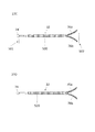
前述のように、鼻は複雑な3次元構造である。鼻の機能又は外観(美観)を改善又は維持する為には、鼻の形状を変更したり、鼻の構造の支持を強化したりすることが望ましい場合があるが、鼻の一側面の変更を、別の部分に悪影響を及ぼさずに行うことが困難である可能性がある。実際、これまでの外科的介入は、鼻弁機能の変化の一因となっており、これに対しては、本明細書に記載のシステム及び方法による処置が行われてよい。本明細書に記載されているのは、鼻を含む体の構造又は形状の一側面を変更又は支持する為に機能するインプラント、装置、システム、及び方法である。図2A及び図2Bは、インプラント32が患者の鼻に埋め込まれて患者の鼻の一組織区画を支持している様子を示す、それぞれ、正面図及び側面図である。インプラント32は、鼻の機能又は外観を維持又は改善することに有用であろう。インプラント32は皮膚及び筋肉の下にあり、皮膚及び筋肉は、インプラントと、下にある鼻構造及びインプラントとをわかりやすく示す為に省略されている。図2A〜2Bは、インプラント32が内鼻弁を支持するか変化させる為に定位置にある様子を示している。インプラント32は、皮膚及び筋肉の下の軟骨及び骨格の層にある複数の構造物を並置している。インプラント32のボディは、近位端34と、遠位端36と、近位端と遠位端との間の中央部38と、を有する。中央部38は、鼻軟骨と患者の皮膚又は筋肉との間に位置する。中央部38は、上部外側軟骨11と、下部外側軟骨の下部外側脚16とを並置している。上述のように、上部外側軟骨の尾方端は、中隔軟骨とともに、内鼻弁角度を画定しており、インプラント32の中央部38は更に、上部外側軟骨11の尾方端48を並置しており、それによって内鼻弁壁の上に位置するか、内鼻弁壁に作用して、内鼻弁の形状を支持するか変化させる。インプラント32の遠位端36は、軟骨及び骨格の上部にある複数の構造物を並置する。図2A〜2Bのこれらの例では、インプラント32の遠位端36はフォーク状であり、第1のアーム40及び第2のアーム42がフォークの歯を形成している。各アームは、近位端がインプラントボディに固定されていて、遠位端がインプラントボディに固定されていない。この例では、アームは、鼻骨4aと、上顎骨の前頭突起6と、上顎鼻骨縫合線7(鼻骨上顎縫合線)とを並置している。変形形態によっては、インプラントの遠位端は、上部層にある1つ以上の構造物、又は中間部又は下部の軟骨及び骨格の層にあるいずれかの構造物又は組織(例えば、副軟骨、大鼻翼軟骨、小鼻翼軟骨、中隔軟骨、上顎骨など)と並置又は近接されてよい。
As mentioned above, the nose has a complex three-dimensional structure. In order to improve or maintain the function or appearance (aesthetics) of the nose, it may be desirable to change the shape of the nose or strengthen the support of the structure of the nose, but change one side of the nose. , Can be difficult to do without adversely affecting other parts. In fact, conventional surgical interventions have contributed to changes in nasal flap function, which may be treated by the systems and methods described herein. Described herein are implants, devices, systems, and methods that function to alter or support one aspect of the structure or shape of the body, including the nose. 2A and 2B are front and side views showing how the
本明細書に開示の送達ツールは、本明細書に開示のインプラント構成を患者の体内のターゲット場所に送達する。送達ツールの例として、鼻インプラント送達ツールがある。 The delivery tool disclosed herein delivers the implant configuration disclosed herein to a target location within the patient's body. An example of a delivery tool is a nasal implant delivery tool.
鼻インプラント及び送達ツールの更なる例が、2014年8月26日に出願された米国特許出願第62/042,209号、並びに2015年8月2日に出願された米国特許出願第14/836,841号に開示されており、これらのそれぞれの全開示内容が参照によって本明細書に組み込まれている。米国特許出願第62/042,209号及び米国特許出願第14/836,841号に開示されている鼻インプラントはいずれも、本明細書に開示の送達ツールとともに使用されてよい。 Further examples of nasal implants and delivery tools are U.S. Patent Application No. 62 / 042,209 filed August 26, 2014, and U.S. Patent Application No. 14/836 filed August 2, 2015. , 841 and the full disclosure of each of these is incorporated herein by reference. Both nasal implants disclosed in U.S. Patent Application No. 62 / 042,209 and U.S. Patent Application No. 14 / 863,841 may be used with the delivery tools disclosed herein.
送達ツールは、鼻インプラントを受けるように適合されたインプラント装填チャンバを含むハンドルと、ハンドルから遠位方向に延びる針であって、内腔を有し、内腔の一部分が非円形断面を有し、鋭利な遠位端を有する針と、鼻インプラントを針内腔に沿って動かし、針の遠位端の開口部から出すように適合されているアクチュエータと、を含んでよい。 The delivery tool is a handle containing an implant loading chamber adapted to receive a nasal implant and a needle extending distally from the handle, having a lumen, and a portion of the lumen having a non-circular cross section. May include a needle with a sharp distal end and an actuator adapted to move the nasal implant along the needle lumen and out the opening at the distal end of the needle.
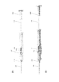
図5は、インプラントを体組織内に配置するインプラント送達装置100を示す。送達装置100は、ハンドル102と、針内腔を有する針104と、プッシュロッド108及びプランジャアセンブリ110を含むアクチュエータ106と、を含む。ハンドル102は、鼻インプラントを受けることに適合されたインプラント装填チャンバ112を含む。
FIG. 5 shows an
インプラント装填チャンバ112は、インプラント装填チャンバ112内にインプラントを配置する為にピンセットを使用することを可能にするように適合されてよい凹部114を含む。凹部114は、配備時構成の鼻インプラントと係合されたピンセットが通るように適合された第1の凹部及び第2の凹部を含んでよい。
The
図6は、ツール100の断面図である。インプラント装填チャンバ112は、針内腔124と連通しており、鼻インプラントを針内腔124に装填するように適合されている。例えば、インプラント装填チャンバ112は、鼻インプラントがインプラント装填チャンバ112から針内腔124内へと前進するにつれて、鼻インプラントを配備時構成から送達時構成に移行させるように適合されてよい。インプラントの送達、並びに、インプラントが患者内のターゲット場所に送達された後の、インプラントからの針内腔の引き抜き/後退が容易に行われるように、針内腔124は、内表面が十分に滑らかであってよい。
FIG. 6 is a cross-sectional view of the
インプラント装填チャンバ112は、針内腔124とインプラント装填チャンバ112との間に配置されたインプラント係合面120と連通してよい。インプラント係合面120は、インプラントを配備時構成から送達時構成へと移行させる為にインプラント32の第1のアーム及び第2のアームと係合するように適合されてよい。実施形態によっては、インプラント係合面は、内表面が十分に滑らかである。内表面を滑らかにすることにより、インプラントが針内腔に向かって前進する際にインプラントの一部がインプラント係合面に引っ掛かる可能性を低減できる。
The
ハンドル102はインプラント方位インジケータ116を含み、これは、針内腔内にあるインプラントの方位に対応する配備時構成の鼻インプラントの第1のアーム及び第2のアームによって形成される平面を視覚的に示すように構成されている。インプラント方位インジケータは、ツールの方位と、対応する、配備時構成の鼻インプラントのアームによって形成される平面の方位とを、ツールの操作者が一目で確認できるように設計されている。インプラント方位インジケータは、装置の使用中にインプラント方位インジケータが操作者の手で隠れたり見えにくくなったりしないように、ハンドルの一部分から延びている。例えば、インプラント方位インジケータ116は、図5に示されるように、ハンドルの遠位端に向かって位置してよい。インプラント方位インジケータは、ハンドルから第1の方向に突き出た第1のアームと、ハンドルから第2の方向に突き出た第2のアームと、を含んでよい。この第1のアーム及び第2のアームは、針内腔内にあるインプラントの方位に対応する、配備時構成の鼻インプラントの第1のアーム及び第2のアームによって形成される平面とほぼ同じ平面を画定する。
The
実施形態によっては、送達ツールは、プッシュロッドがハンドルに対して更に近位方向に動くことを防ぐように構成されたプッシュロッドロック要素を、インプラント装填チャンバの近位側に含む。プッシュロッドロック要素は、プッシュロッドがハンドルの内部部分の外側に滑り抜けることを防ぐように構成されてよい。図6は、プッシュロッドロック要素122を示す。図示されているプッシュロッドロック要素122は、プッシュロッド108上のノッチ132(図17)と係合して、プッシュロッド108がハンドル102に対して更に後退することを防ぐように構成されている。
In some embodiments, the delivery tool includes a push rod locking element configured proximal to the implant loading chamber to prevent the push rod from moving further proximal to the handle. The push rod locking element may be configured to prevent the push rod from slipping out of the inner portion of the handle. FIG. 6 shows the push
送達ツールのアクチュエータは、プッシュロッド及びプランジャアセンブリを含んでよい。実施形態によっては、圧縮要素がプッシュロッドとプランジャアセンブリとをつないでよい。図16では、圧縮要素130がプッシュロッド108とプランジャアセンブリ110とをつないでいるように示されている。圧縮要素130は、ツールが患者から除去されるか引き抜かれる際にインプラントが後退又は摺動することを防ぐために、遠位方向の更なる軸力をインプラントにかけることが可能である。
Actuators for delivery tools may include push rods and plunger assemblies. In some embodiments, a compression element may connect the push rod to the plunger assembly. In FIG. 16, the
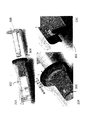
図7は、インプラント32がインプラント送達装置100のインプラント装填チャンバ112内に配置された様子を示す。インプラント装填チャンバ112は、(例えば、インプラントのアームが広がっている)配備時構成のインプラント32を受けるように構成されている。
FIG. 7 shows how the
図8Aに示される送達ツール100は、プッシュロッド108及びプランジャアセンブリ110が後退位置にあって、インプラント装填チャンバ112がプッシュロッド108によってふさがれていない。図8Bでは、インプラント32がインプラント装填チャンバ内に配置されている。
In the
図9Aに示される送達ツール100は、プランジャアセンブリ110及びプッシュロッド108が前進して、インプラントをインプラント装填チャンバから針内腔内へと押している。図9Aでは、インプラントは配備前停止点にあり、インプラントは針内腔に収容されている。
In the
図9Bでは、プッシュロッド108及びプランジャアセンブリ110は、図9Aに示された構成より前進しており、インプラントは、針内腔124の外に向けて遠位方向に押されるところである。図15は、プッシュロッド108及びプランジャアセンブリ110が遠位方向に前進した位置にあるインプラント送達装置の断面図である。
In FIG. 9B, the
図10Aは、プッシュロッド108及びプランジャアセンブリ110が遠位方向に前進した位置にあるツール100の断面図である。図10Bに示されるツール100の断面図では、プッシュロッド108及びプランジャアセンブリ110が後退位置にあって、プッシュロッド108はプッシュロッドロック要素122と係合しており、インプラント装填チャンバ112はインプラントを受ける準備ができている。
FIG. 10A is a cross-sectional view of the
図11〜12は、インプラント装填チャンバ112内に配置された後のインプラント32を示す。図13は、針内腔124内にあるインプラント32を示す。インプラント32は、針内腔124内にあるときには、圧縮された送達時構成である。プッシュロッド108は、針内腔124内でインプラント32を遠位方向に前進させているように示されている。図14は、インプラント32が針104の遠位端を過ぎて遠位方向に延びている様子を示している。インプラント32のアーム78a、78bは、インプラント32が針内腔124から出るにつれて配備時構成に移行することが可能である。
11-12 show the
図16は、アクチュエータ106の拡大図であり、プッシュロッド108が圧縮要素130を介してプランジャアセンブリ110と係合している様子を示している。圧縮要素130は、インプラントが体組織内に配備されてからプッシュロッド108が最初に後退するときに、配備された場所及び位置からインプラントが移動する可能性を減らす為に、プッシュロッド108に遠位方向の軸力をかけることが可能である。
FIG. 16 is an enlarged view of the
図17は、ハンドル102の一部分の拡大図であり、プッシュロッド108がプッシュロッドロック要素122と係合している様子を示している。プッシュロッドロック要素122は、ノッチ132においてプッシュロッド108と係合することにより、プッシュロッド108がハンドル102に対して更に後退することを防ぐことが可能である。
FIG. 17 is an enlarged view of a part of the
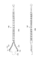
送達ツールは、様々なサイズ及び形状のインプラントとともに使用されるように適合されてよい。例えば、送達ツールは、様々な長さ及び構成のインプラントに対応するように調節可能である。インプラント装填チャンバは、様々なサイズ及び形状のインプラントがインプラント装填チャンバを通って送達ツールのハンドルの中に入っていけるように調節可能である。インプラントの様々な長さに対応する為に、送達ツールの1つ以上の部品が、複数の位置の間で調節可能である。一例では、針は、ハンドルに対して可動であってよい。針は、複数の離散的な位置の間で、ハンドルに対して可動であってよい。それらの複数の離散的な位置は、鼻インプラントの長さに対応してよい。例えば、インプラントが短い場合には、針を近位方向に後退させて、ハンドルから外に延びる針の長さを実質的に短くすることが可能である。一例では、針スライダアクチュエータが、針を、複数の離散的な位置の間でハンドルに対して動かすように構成される。図20はインプラント送達装置ハンドル230を示しており、これは針スライダアクチュエータ232を有する。針スライダアクチュエータ232は、インプラントの長さに対応する為に、針234を複数の位置の間で軸方向にスライドさせることが可能である。場合によっては、スライダは、インプラント係合面236及び針234を動かすことも可能である。
Delivery tools may be adapted for use with implants of various sizes and shapes. For example, the delivery tool can be adjusted to accommodate implants of various lengths and configurations. The implant loading chamber is adjustable so that implants of various sizes and shapes can enter the handle of the delivery tool through the implant loading chamber. One or more parts of the delivery tool can be adjusted between multiple positions to accommodate the various lengths of the implant. In one example, the needle may be movable with respect to the handle. The needle may be movable relative to the handle between multiple discrete positions. Their multiple discrete locations may correspond to the length of the nasal implant. For example, if the implant is short, the needle can be retracted proximally to substantially reduce the length of the needle extending out of the handle. In one example, a needle slider actuator is configured to move the needle with respect to the handle between multiple discrete positions. FIG. 20 shows the implant
別の例では、インプラントの様々な長さに対応する為に、ツールに対してアクチュエータを調節することが可能である。例えば、アクチュエータの長さが、第1の位置と第2の位置との間で調節可能であってよい。プッシュロッド及びプランジャアセンブリの長さが、第1の位置と第2の位置との間で調節可能であってよく、これは、プッシュロッドを、プランジャアセンブリ上の第1のロック面、及びプランジャアセンブリ上の第2のロック面と係合させることにより調節可能であってよい。図18A〜18Bは、2つの離散的位置にあるアクチュエータ200を示す。プッシュロッド202は、異なる2つの位置206、208でプランジャアセンブリ204と係合されてよい。プランジャアセンブリ204のノブ205は、回すことによって2つの位置206、208の間でスライドできる。プッシュロッド202及びプランジャアセンブリ204の長さが使用中は固定されるように、プランジャアセンブリ204がロック又は係合されてよい。図19は、別の構成としてアクチュエータ220を示しており、ここでは、トーションばね222を使用して、プランジャアセンブリ224を離散位置226、228の間に固定する。
In another example, it is possible to adjust the actuator with respect to the tool to accommodate the various lengths of the implant. For example, the length of the actuator may be adjustable between the first position and the second position. The length of the push rod and plunger assembly may be adjustable between the first and second positions, which allows the push rod to be placed on the first locking surface on the plunger assembly and the plunger assembly. It may be adjustable by engaging with the upper second locking surface. 18A-
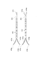
実施形態によっては、送達ツールは、1つ以上の鼻インプラントを収容しているカートリッジをインプラント装填チャンバで受けるように適合されてよい。インプラント装填チャンバは、鼻インプラントを収容しているカートリッジを受けるように適合されてよい。図21はインプラント送達装置240を示しており、これは、ハンドル241と、インプラント244を有するカセット/カートリッジ242とを有する。カセット又はカートリッジ242は、1つ以上の鼻インプラント244を含んでよい。ハンドル241は、カートリッジ242を受けて、鼻インプラント244がプッシュロッドに押されてカートリッジ242から針内腔へと前進できるように構成されてよい。場合によっては、カートリッジ242は、2つ以上の鼻インプラントを収容するように構成されてよい。
In some embodiments, the delivery tool may be adapted to receive a cartridge containing one or more nasal implants in the implant loading chamber. The implant loading chamber may be adapted to receive the cartridge containing the nasal implant. FIG. 21 shows an
カートリッジは、針内腔と連通するように適合されてよい。インプラントは、カートリッジ内から直接針内腔内に移動してよい。場合によっては、送達装置は、カートリッジと針内腔との間にインプラント係合面が配置されてよい。カートリッジは、インプラントを配備時構成と送達時構成との間で移行させる為にインプラントの第1のアーム及び第2のアームと係合するように適合されたインプラント係合ランプを含んでもよい。例えば、インプラント係合ランプは、インプラントがインプラント係合ランプから針内腔内に前進できるように、インプラントの第1のアーム及び第2のアームを圧縮構成にすることが可能である。 The cartridge may be adapted to communicate with the needle lumen. The implant may move directly from within the cartridge into the needle lumen. In some cases, the delivery device may have an implant engaging surface placed between the cartridge and the needle lumen. The cartridge may include an implant engagement lamp adapted to engage the implant's first and second arms to transition the implant between the deployment and delivery configurations. For example, the implant engagement lamp can have a compression configuration of the first and second arms of the implant so that the implant can advance from the implant engagement lamp into the needle lumen.
実施形態によっては、ハンドルは、カートリッジを受けて、カートリッジが針と係合して、針の長さをハンドルに対して調節するように適合されてよい。送達ツールは、様々なサイズのインプラントを収容する、様々なサイズのカートリッジを受けるように適合されてよい。カートリッジサイズは、カートリッジがハンドルと係合して、針内腔の長さが、カートリッジに収容されている鼻インプラントに合わせて調節されるように設計されてよい。別の代替形態では、カートリッジは、アクチュエータの長さを調節することによってアクチュエータと針内腔との間の相対距離を調節するように構成されてよい。 In some embodiments, the handle may be adapted to receive the cartridge so that the cartridge engages the needle and adjusts the length of the needle relative to the handle. Delivery tools may be adapted to receive cartridges of various sizes, accommodating implants of various sizes. The cartridge size may be designed so that the cartridge engages the handle and the length of the needle lumen is adjusted to the nasal implant contained in the cartridge. In another alternative embodiment, the cartridge may be configured to adjust the relative distance between the actuator and the needle lumen by adjusting the length of the actuator.
送達ツールは、インプラント又は送達ツールの状態に関する信号を出力するように構成されたインジケータを含んでよい。実施形態によっては、針は、針に沿う様々な位置に概ね縞模様のマーキングを含んでよい。 The delivery tool may include an indicator configured to output a signal regarding the condition of the implant or delivery tool. In some embodiments, the needle may include generally striped markings at various locations along the needle.
実施形態によっては、送達ツールの針は、外表面に低摩擦コーティングが施されている。場合によっては、鼻組織の一部を貫通することが困難な可能性がある。低摩擦コーティングを施すことにより、鼻組織の一部に対して針を貫通及び移動させやすくすることが可能である。低摩擦コーティングにより、体組織内での針の挿入時及び後退時の、組織と針との間の引きずり力を減らすことが可能である。一般に、低摩擦コーティングは、針に粘着可能な、生体適合性且つ潤滑性の材料で作られてよい。低摩擦コーティングに使用可能な材料の例として、PTFE、シリコーン、ポリ(p−キシリレン)ベースのポリマーなどがある。適切なポリ(p−キシリレン)ベースのポリマーの一例は、パリレン(Parlyene)という商品名で入手可能である。 In some embodiments, the delivery tool needle has a low friction coating on the outer surface. In some cases, it can be difficult to penetrate part of the nasal tissue. By applying a low friction coating, it is possible to facilitate the penetration and movement of the needle through a portion of the nasal tissue. The low friction coating can reduce the drag force between the tissue and the needle during insertion and retraction of the needle within the body tissue. In general, the low friction coating may be made of a biocompatible and lubricating material that is sticky to the needle. Examples of materials that can be used for low friction coatings include PTFE, silicones, poly (p-xylylene) based polymers and the like. An example of a suitable poly (p-xylylene) based polymer is available under the trade name Parlyene.
送達ツールは、鼻インプラントが針内腔の遠位端にあるときのアクチュエータの位置を示すように適合されたアクチュエータレジスタを含んでよい。アクチュエータレジスタは、アクチュエータ上又はハンドル上にマーキングを含んでよい。アクチュエータレジスタは、インプラントの少なくとも遠位部分が針内腔から外に出たときのアクチュエータの位置を示すように適合されてよい。 The delivery tool may include an actuator register adapted to indicate the position of the actuator when the nasal implant is at the distal end of the needle lumen. Actuator registers may include markings on the actuator or on the handle. The actuator register may be adapted to indicate the position of the actuator when at least the distal portion of the implant exits the needle lumen.
実施形態によっては、アクチュエータレジスタは、アクチュエータが更に動くことを防ぐストッパ要素である。図22A〜22Eは、様々な構成のインプラント送達装置のアクチュエータの一部を示す。図22Aは、送達ツール302に挿入される前のプランジャ300を示している。送達ツール302は、テールシース304を含む。プランジャ300は、送達ツール302内で受けられ、テールシース304と係合する。送達ツール302はストッパ306を含み、ストッパ306は、送達ツール302が図22Bのインプラント装填モードにあるときにプランジャ300の前進を阻止する。図22Bは、テールシース304に対して第1の構成にあるプランジャ300を示しており、ストッパ306がインプラントの装填を可能にしている。プランジャ300は、ナチュラルばね(図22C)又は他のストッパにぶつかって止められてよい。プランジャ300は、装填モード(図22B〜22C)から配備モード(図22D〜22E)に移行する為に回されるかねじられてよい(又はテールシース304が調節されてよい)。ねじられて配備モードになると、ハンドル上の形状308又は装置の他の部分によってばね機構又はストッパが動かされるか強制的に開かれてよく、これによって、プランジャ300が前進してストッパ306を通過することが可能になる。配備モードでは、プランジャ300は、更に前進してインプラントを配備することが可能である。
In some embodiments, the actuator register is a stopper element that prevents the actuator from moving further. 22A-22E show some of the actuators of implant delivery devices of various configurations. FIG. 22A shows the
実施形態によっては、送達ツールは、スナップ機構又ははめ合いポケットを含んでよい。スナップ機構をはめ合いポケットに動かすかスナップすると、可聴の「クリック」音、「スナップ」音、又は他の音が鳴ってよい。スナップ機構は、はめ合いポケットと関連してロック又は保持されてよい。インプラントが送達ツール内の特定の位置にあるか、インプラントが部分的又は完全に配備されると、はめ合い機構がはめ合いポケットに入ってよい。実施例によっては、インプラントの位置(例えば、遠位位置、配備位置)などをインジケータで示すステップが含まれる。はめ合い機構の、ハンドルからの取り外し又はロック解除は、例えば、ハンドルのポケット内のスナップ機構を手でへこますことによって行われてよい。これは、例えば、プランジャをゆるめて、追加の(第2、第3などの)インプラントを送達ツールに再装填する場合に有用でありうる。インジケータは、インプラントが(送達ツール内の定位置に)装填されているという信号、インプラントの一部が針の外に出ている(例えば、インプラントの遠位部分が針の外に出ている)という信号、或いは、インプラント全体が針の外に出ることが可能であるという信号を出力してよい。信号は、例えば、可聴信号(例えば、ビープ、ブザー、音声など)、可触信号(例えば、振動信号)、可視信号(例えば、着色光又は白色光、閃光又は持続光)などであってよい。 In some embodiments, the delivery tool may include a snap mechanism or a fitting pocket. When the snap mechanism is moved into the mating pocket or snapped, an audible "click", "snap", or other sound may be heard. The snap mechanism may be locked or held in association with the fitting pocket. Once the implant is in a specific position within the delivery tool or the implant is partially or fully deployed, the fitting mechanism may enter the fitting pocket. Some embodiments include steps to indicate the position of the implant (eg, distal position, deployment position) and the like with indicators. The fitting mechanism may be removed or unlocked from the handle, for example, by manually denting the snap mechanism in the handle pocket. This can be useful, for example, when loosening the plunger and reloading additional (second, third, etc.) implants into the delivery tool. The indicator is a signal that the implant is loaded (in place in the delivery tool), part of the implant is out of the needle (eg, the distal part of the implant is out of the needle). Or the signal that the entire implant is capable of exiting the needle may be output. The signal may be, for example, an audible signal (eg, beep, buzzer, voice, etc.), a touchable signal (eg, vibration signal), a visible signal (eg, colored or white light, flash or sustained light), and the like.
実施例によっては、針の遠位端は、鼻又は顔の組織(例えば、本明細書に記載のいずれか)に穴をあけるのに十分な鋭利さを有してよい。遠位端が鋭利であれば、鼻の引き裂きを最小限に抑えることが可能である。針は任意のサイズであってよく、例えば、当該技術分野において知られている皮下注射針のサイズであってよく、例えば、外径が8ゲージ、10ゲージ、12ゲージ、14ゲージ、16ゲージ、18ゲージ、20ゲージなどであってよい。針のサイズは、鼻及び顔の粘膜と上皮と筋肉皮膜と軟骨又は骨との間に適合するように決定されてよい。実施例によっては、針は、鼻の粘膜/皮膚と軟骨との間に適合してよい。針は、組織を貫通してインプラントを配置するのに十分な長さであってよい(例えば、少なくとも50mm、少なくとも75mm、少なくとも100mm、少なくとも115mm、少なくとも125mm、又は少なくとも150mmであってよい)。針の遠位端は、インプラントが内側にぴったり収まるように適合された開口部を含んでよい。針は、インプラントを収容又は保持するように適合されてよい内腔を有する。内腔は、任意の断面輪郭を有してよく、例えば、円形、非円形、長円形又は卵形、楕円形、三角形、正方形、長方形、六角形などの断面輪郭を有してよい。変形形態によっては、内腔の様々な領域が様々な断面輪郭を有してよい。断面が非円形である内腔の方位が、送達ツールのハンドルを基準として決定されてよく、これにより、送達ツールのハンドルで、内腔の方位を制御すること(並びに、内腔内で決定されるインプラントの方位を制御すること)が可能である。インプラント送達中のインプラントの方位をハンドルで制御することが可能である。内腔は、1個、2個、又は2個、3個、4個、5個、又は、2個超、3個超、4個超、又は5個超の、異なる断面輪郭を有してよい。例えば、近位部分は円形であってよく、遠位部分は非円形であってよい。実施例によっては、近位内腔領域が円形であってよく、中間内腔領域が非円形(例えば、長円形、卵形、楕円形、又は他の任意の、上述されたものを含む形状)であってよく、遠位内腔領域が円形であってよい。断面が非円形である内腔は、長軸及び短軸を有してよい。インプラントは、針の内腔、又はハンドルの内腔と係合するように構成されてよく、或いは、係合してよい。ハンドル内腔又は針内腔に配置されたインプラントは、その遠位端に第1及び第2のアームを有してよく、第1及び第2のアームは、それぞれ、近位端がインプラントに固定されていてよく、遠位端がインプラントに固定されていなくてよく、各アームの遠位端は、インプラントの中心長手軸から離れて針内腔内での送達時構成から針内腔外での配備時構成へと移行するように付勢されていてよく、第1及び第2のアームは、それぞれが、長軸の対向する両端部において針内腔の内表面と係合するベベル面(例えば、外側ベベル面)を含む。実施例によっては、挿入するステップの間にインプラントと内腔(針)との間で既知の方位を維持するステップが含まれる。 In some embodiments, the distal end of the needle may be sharp enough to puncture nose or facial tissue (eg, any of those described herein). A sharp distal end can minimize nasal tearing. The needle may be of any size, eg, the size of a hypodermic needle known in the art, eg, outer diameters of 8 gauge, 10 gauge, 12 gauge, 14 gauge, 16 gauge. It may be 18 gauge, 20 gauge, or the like. The size of the needle may be determined to fit between the mucous membranes of the nose and face, the epithelium, the musculoskeletal system and the cartilage or bone. In some embodiments, the needle may fit between the nasal mucosa / skin and cartilage. The needle may be long enough to penetrate the tissue and place the implant (eg, it may be at least 50 mm, at least 75 mm, at least 100 mm, at least 115 mm, at least 125 mm, or at least 150 mm). The distal end of the needle may include an opening fitted so that the implant fits snugly inside. The needle has a lumen that may be adapted to accommodate or hold the implant. The lumen may have any cross-sectional contour, such as circular, non-circular, oval or oval, oval, triangular, square, rectangular, hexagonal. Depending on the deformation form, different regions of the lumen may have different cross-sectional contours. The orientation of the lumen, which has a non-circular cross section, may be determined relative to the handle of the delivery tool, which allows the handle of the delivery tool to control the orientation of the lumen (as well as be determined within the lumen). It is possible to control the orientation of the implant. It is possible to control the orientation of the implant during implant delivery with the handle. Lumens have different cross-sectional contours of 1, 2, or 2, 3, 4, 5, or more than 2, more than 3, more than 4, or more than 5. good. For example, the proximal portion may be circular and the distal portion may be non-circular. In some embodiments, the proximal lumen region may be circular and the intermediate lumen region may be non-circular (eg, oval, oval, oval, or any other shape including those described above). The distal lumen region may be circular. A lumen having a non-circular cross section may have a major axis and a minor axis. The implant may be configured to engage or may engage with the lumen of the needle, or the lumen of the handle. Implants placed in the handle or needle lumen may have first and second arms at their distal ends, the first and second arms each having a proximal end fixed to the implant. The distal end may not be fixed to the implant, and the distal end of each arm may be extra-needle lumen from the delivery configuration within the needle lumen away from the central longitudinal axis of the implant. The first and second arms may be urged to transition to a deployable configuration, each with a bevel surface (eg,) that engages the inner surface of the needle cavity at opposite ends of the major axis. , Outer bevel surface) included. Some embodiments include the step of maintaining a known orientation between the implant and the lumen (needle) during the insertion step.
ガイドがインプラントを誘導することが可能であるが、ガイドは一般にアクチュエータを誘導する。ガイドとアクチュエータは、相補的な形状であってよい。例えば、ガイドはトラフであってよく、アクチュエータは、トラフ内に途中までぴったり入るロッドであってよい。一般に、アクチュエータがガイド内で定位置にあるときには、アクチュエータが送達ツールを通してインプラントに作用する(インプラントを動かす)ことが可能であるように、アクチュエータの一部がガイドの上方に位置する。 Guides can guide the implant, but guides generally guide the actuator. The guide and actuator may have complementary shapes. For example, the guide may be a trough and the actuator may be a rod that fits halfway into the trough. Generally, when the actuator is in place within the guide, a portion of the actuator is located above the guide so that the actuator can act on the implant (move the implant) through the delivery tool.
アクチュエータは、1つ以上のマーキングを含んでよい。マーキングは、送達ツール又はインプラントに対するアクチュエータの相対位置を示してよい。例えば、マーキングは、インプラントが組織内でインプラント配備の所望の場所にあること、インプラントの遠位端が送達ツールの遠位端にあること、インプラントが部分的配備位置にあること、インプラントが組織内に完全に送達(配備)されたことなどを示すように構成されてよい。マーキングは、インプラントが、ある位置にあること、配備されようとしていること(配備直前の位置にあること)、部分的に配備されたこと、又は完全に配備されたことを示す為に有用でありうる。例えば、マーカは、インプラントのアーム(フォーク領域)が配備及び展開され、インプラントの残り部分が送達ツール内にあるときに、そのことを示してよい。マーキングは、アクチュエータ又はインプラントの(例えば、送達ツールに対する)位置を示すものであれば、どのようなタイプのマーキングであってもよく、例えば、線、複数の線、太線、突起、リング、色、蛍光マーカであってよい。インプラントの配備を完了する為に(例えば、インプラントの、アームを含まない部分(例えば、インプラントボディ)を組織から出す為に)、送達ツールを組織から引き抜くことが可能であり、これは、アクチュエータによってインプラントを(組織内の)定位置に保持したまま針を引き抜くことなどにより、可能である。アクチュエータは、何らかの理由、例えば、今述べた理由などにより、1個、2個、3個、4個、5個、又は6個以上のマーキングを含んでよい。更に、アクチュエータは、様々な長さのインプラントに対応する様々なマーキングを有してよい。アクチュエータは更に、アクチュエータが送達ツール内で更に動くことを防ぐストッパ機構を含んでよい。 The actuator may include one or more markings. The marking may indicate the relative position of the actuator with respect to the delivery tool or implant. For example, the markings are that the implant is in the tissue at the desired location for implant deployment, that the distal end of the implant is at the distal end of the delivery tool, that the implant is in a partial deployment position, that the implant is in tissue. It may be configured to indicate that it has been completely delivered (deployed) to. Markings are useful to indicate that the implant is in place, is about to be deployed (immediately before deployment), has been partially deployed, or has been fully deployed. sell. For example, markers may indicate when the implant's arm (fork area) is deployed and deployed and the rest of the implant is within the delivery tool. The marking may be of any type as long as it indicates the position of the actuator or implant (eg, with respect to the delivery tool), eg, line, multiple lines, thick line, protrusion, ring, color, etc. It may be a fluorescent marker. To complete the deployment of the implant (eg, to remove the arm-free portion of the implant (eg, the implant body) from the tissue), the delivery tool can be withdrawn from the tissue, which is done by the actuator. This is possible, for example, by pulling out the needle while holding the implant in place (in the tissue). The actuator may include one, two, three, four, five, or six or more markings for some reason, for example, just mentioned. In addition, the actuator may have different markings for implants of different lengths. The actuator may further include a stopper mechanism that prevents the actuator from moving further within the delivery tool.
本明細書に記載の送達ツールと1つ以上の鼻インプラントとを含むシステムも提供される。本明細書に記載の送達ツールと鼻インプラントを収容するカートリッジとを含むシステムも提供される。カートリッジは、2つ以上の鼻インプラントを収容することが可能である。実施形態によっては、カートリッジは、インプラントを送達時構成に移行させるように構成されたインプラント係合面を含んでよい。 A system including the delivery tools described herein and one or more nasal implants is also provided. A system is also provided that includes the delivery tools described herein and a cartridge that houses a nasal implant. The cartridge can accommodate more than one nasal implant. In some embodiments, the cartridge may include an implant engaging surface that is configured to transition the implant into a delivery configuration.
上述のように、インプラントの配置は、痛みや傷を最小限に抑える為に、体の小さな開口部を利用する低侵襲的な方法で行われてよい。しかしながら、インプラントを小さな開口部より大きくすることが有利である場合があり、これは、例えば、組織の治療対象領域が体の小さな開口部より大きい場合である。そのような場合には、インプラントを縮小構成で開口部を通して配置してよく、体内での配置中又は配置後に展開してよい。更に、挿入中に展開されたインプラントが組織に力をかけることが可能である(例えば、この力は、インプラントを定位置に保持することに役立ちうる)。変形形態によっては、送達ツールは、インプラントを、展開構成の状態で受け入れ、体の小さな開口部を何とか通り抜けるように縮小してから体組織に送達するように構成されてよい。インプラントは、縮小構成のままで送達されてよい。インプラントは、展開構成で送達されてよく、或いは送達中に展開されてよい。送達ツールは、インプラントを展開構成で送達ツールに装填する装填チャンバと、インプラントの形状を変化させる1つ以上の整形チャンバとを含んでよい。送達ツールは、針内腔と連通していて、鼻インプラントを針内腔内に装填するように適合されたインプラント装填チャンバを含んでよい。 As mentioned above, implant placement may be done in a minimally invasive manner utilizing small openings in the body to minimize pain and injury. However, it may be advantageous to make the implant larger than the small opening, for example, when the area of tissue to be treated is larger than the small opening of the body. In such cases, the implant may be placed in a reduced configuration through the opening and deployed during or after placement within the body. In addition, the implant deployed during insertion can exert a force on the tissue (eg, this force can help hold the implant in place). Depending on the variant, the delivery tool may be configured to accept the implant in a deployed configuration, shrink it somehow through a small opening in the body, and then deliver it to body tissue. The implant may be delivered in a reduced configuration. Implants may be delivered in a deployed configuration or may be deployed during delivery. The delivery tool may include a loading chamber for loading the implant into the delivery tool in a deployed configuration and one or more shaping chambers that change the shape of the implant. The delivery tool may include an implant loading chamber that communicates with the needle lumen and is adapted to load the nasal implant into the needle lumen.
装填チャンバは、一般に矩形形状であってよいが、インプラントを(例えば、展開構成で)受け入れることが可能であって、(例えば、プランジャ/アクチュエータによって)インプラントを装填チャンバに通して動かすことが可能であれば、卵形又は別の形状であってもよい。装填チャンバは、上部が塞がれていてよいが(ルーフを有してよいが)、一般には、インプラントの挿入を可能にする為に上部が開いている。装填チャンバは、フロアを有し、一般には、第1及び第2の横壁(側部)と近位壁及び遠位壁(端部)とを有し、近位壁及び遠位壁は、それぞれが第1及び第2の横壁と(例えば、一方の端で)つながっている。近位壁及び遠位壁は、それぞれが開口部を有してよく、近位壁の開口部は、プランジャ/アクチュエータが装填チャンバに入ることを可能にするように構成されていて、遠位壁の開口部は、針内腔と開放連通している。装填チャンバの近位壁は、インプラント、又はアクチュエータのプランジャが通り抜けることを可能にするように構成された開口部を有してよい。インプラントは、装填チャンバのフロアに横たわるように、上部から装填チャンバ内に配置されて(落とされて)よい。 The loading chamber may generally be rectangular in shape, but the implant can be accepted (eg, in a deployed configuration) and the implant can be moved through the loading chamber (eg, by a plunger / actuator). If there is, it may be oval or another shape. The loading chamber may be closed at the top (although it may have a roof), but is generally open at the top to allow implant insertion. The loading chamber has a floor and generally has first and second lateral walls (sides) and proximal and distal walls (ends), with the proximal and distal walls being the respective. Is connected to the first and second side walls (eg, at one end). The proximal wall and the distal wall may each have an opening, the proximal wall opening being configured to allow the plunger / actuator to enter the loading chamber and the distal wall. The opening of the needle is openly communicated with the lumen of the needle. The proximal wall of the loading chamber may have an opening configured to allow the implant, or actuator plunger, to pass through. Implants may be placed (dropped) in the loading chamber from above so that they lie on the floor of the loading chamber.
装填チャンバ、整形チャンバ/インプラント係合面、及び針を使用して上述のようにインプラントを整形することは、インプラントが送達ツール内で展開構成から縮小構成に移行しさえすれば、別の方法で実施されてもよい。例えば、インプラント送達ツールは装填チャンバだけを有してよく、装填チャンバは、整形チャンバを使用せずに上述のようにインプラントを整形してよく、インプラントは、装填チャンバから針に直接移動してよい。インプラント送達ツールは、複数の整形チャンバを有してよく、それぞれは、インプラント構成を少しずつ変化させてよい。整形チャンバは、卵形であってよく、或いは矩形であってよく、或いは他の形状であってもよい。 Shaping the implant as described above using the loading chamber, shaping chamber / implant engagement surface, and needle is another method as long as the implant transitions from the deployed configuration to the reduced configuration within the delivery tool. It may be carried out. For example, the implant delivery tool may have only a loading chamber, which may shape the implant as described above without using a shaping chamber, and the implant may move directly from the loading chamber to the needle. .. The implant delivery tool may have multiple orthopedic chambers, each of which may vary the implant configuration in small increments. The shaping chamber may be oval, rectangular, or other shape.
インプラントは、埋め込み時に(インプラントが針から出て体組織に入る埋め込み動作の間に)様々な形状又は様々な構成を呈してよい。インプラント32は、組織内での埋め込み中に送達時構成から配備時構成に移行してよい。1つ以上の遠位アームがインプラントの中心長手軸から離れることにより、インプラントは、縮小構成又は圧縮構成から展開構成に移行することが可能である。アーム(例えば、アームの遠位端)は、中心長手軸から離れるように付勢されてよい。アームは、まっすぐに出てよいが、一般には、アームの遠位端が曲がって中心長手軸から離れるように分岐する。アーム間で組織を捕らえることが可能である。アームを分岐させることは、力を組織の広い領域に分散させることに役立ちうる。鼻組織内では、テント状になることや遠位方向への移動を防ぐか、最小限に抑えることが可能である。アームを分岐させることにより、針又は送達装置の引き抜き時にインプラントを定位置に保持することも可能である。ベベルは、アームの分岐を支援することが可能である。組織内を動く際に、アームの動きが、アームの遠位端の半径方向内側の面にあるベベルによって支援されることが可能である。ベベルは、組織内を切り進んで、組織内にアームを誘導することが可能である。図示されているのはベベル付きのアームを2本有するインプラントであるが、インプラントは、ベベルがなくてもよく、ベベルが1個でもよく、各アームに1個のベベルがあってよく、各アームに2個のベベルがあってもよく、その他であってもよく、0個、1個、2個、3個、4個、又は5個以上のアームを有してよい。インプラントは、アクチュエータ/プランジャによって体組織内へ前進して(押されて)よい。
Implants may exhibit different shapes or configurations at the time of implantation (during the implant movement as the implant exits the needle and enters body tissue). The
縮小姿勢にあるインプラントは、そのまま組織内に配備されてから、縮小構成から送達時構成に移行してよいが、一般には、配備前に方向づけられてよい。インプラントは、送達ツールハンドル内で方向づけられてよいが、一般には、針内で方向づけられる。インプラントは、(送達ツールハンドル内、又は針内の)非円形内腔によって方向づけられてよい。長軸及び短軸を有する非円形内腔によって、インプラントのアームが長軸の外側方向に(且つ、中心長手軸から離れるように)(わずかに)分岐することが可能になってよく、これによって、インプラントを(アームを介して)長軸の方向に方向づけることが可能になってよい。これは、例えば、プランジャがインプラントツールハンドル内でインプラントを移動させているときに行われてよいが、一般には、インプラントが針内を移動しているときに行われる。実施例によっては、インプラントが方向づけられた後に針が円形断面領域になってよく、インプラントは、その方位を維持しながら、円形断面領域内を移動することが可能である。例えば、円形断面領域内の移動距離は、比較的短くてよい。 Implants in a reduced position may be deployed as-is in the tissue and then transitioned from a reduced configuration to a on-delivery configuration, but generally may be oriented prior to deployment. The implant may be oriented within the delivery tool handle, but is generally oriented within the needle. The implant may be oriented by a non-circular lumen (in the delivery tool handle or in the needle). A non-circular lumen with a major axis and a minor axis may allow the implant arm to bifurcate (and slightly) outward of the major axis (and away from the central longitudinal axis). , It may be possible to orient the implant in the direction of the major axis (via the arm). This may be done, for example, when the plunger is moving the implant within the implant tool handle, but is typically done when the implant is moving within the needle. In some embodiments, the needle may become a circular cross-section region after the implant has been oriented, allowing the implant to move within the circular cross-section region while maintaining its orientation. For example, the distance traveled within the circular cross-section region may be relatively short.
インプラントは、針内腔の外側において、針内腔内での送達時構成から、配備時構成に移行することが可能である。インプラントが針の遠位端から出る際に、アームは互いに離れるように移動する(分岐する)ことが可能である。インプラントは、インプラントツールがインプラントから引き抜かれる前に完全に配備されることが可能であり、或いは、インプラントは部分的に配備されることが可能である(例えば、インプラントのアーム以外の部分が送達ツールの針内に配置されていながら、アームが配備されてよく、アームが配備された時点で、針がインプラントから引き抜かれて組織から離されることにより、インプラントが定位置に残されることが可能である)。実施例によっては、アクチュエータは、インプラントを組織内へ更に押すことが可能である(アーム上の内側ベベルの支援により、アームを組織内へ動かすことが可能である)。別の例では、送達ツールがインプラント及びアクチュエータから引き抜かれる際に、アクチュエータがインプラントを定位置に保持することが可能であり、その後、アクチュエータが引き抜かれると、インプラントが組織内の定位置に残る。組織内を切り進む内側ベベルによる支援を受け、且つ/又は、付勢されているアームが、付勢されていない構成に戻ろうとすることによる支援を受け、インプラントは組織内を移動することが可能である。インプラントは、送達装置の遠位端から出る際に、配備時構成から送達時構成に移行することが可能である。 The implant can transition from a delivery-time configuration within the needle lumen to a deployment-time configuration outside the needle lumen. As the implant exits the distal end of the needle, the arms can move (branch) away from each other. The implant can be fully deployed before the implant tool is withdrawn from the implant, or the implant can be partially deployed (eg, the part other than the implant's arm is the delivery tool). The arm may be deployed while being placed within the needle of the implant, and at the time the arm is deployed, the implant can be left in place by being pulled out of the implant and separated from the tissue. ). In some embodiments, the actuator can push the implant further into the tissue (with the help of an inner bevel on the arm, the arm can be moved into the tissue). In another example, the actuator can hold the implant in place as the delivery tool is withdrawn from the implant and actuator, and then when the actuator is withdrawn, the implant remains in place in the tissue. The implant can move within the tissue with the support of an inner bevel that cuts through the tissue and / or with the help of the urged arm attempting to return to an unurged configuration. Is. The implant can transition from a deployable configuration to a deliverable configuration as it exits the distal end of the delivery device.
実施形態によっては、インプラントを前進させるステップは、インプラントの第1のアーム及び第2のアームがそれぞれ組織と係合することによってインプラントの中心長手軸から離れるように、インプラントを遠位方向に押すステップを含む。実施形態によっては、インプラントを前進させるステップは、送達ツールの一部(例えば、針)を後退させて、インプラントの第1のアーム及び第2のアームが自己展開してインプラントの中心長手軸から離れることを可能にするステップを含んでよい。場合によっては、前進させるステップは、押すステップと後退させるステップとの組み合わせを含んでよい。例えば、インプラントを前進させるステップは、第1のアーム及び第2のアームがそれぞれ組織と係合することによってインプラントの中心長手軸から離れるように、インプラントを遠位方向に押し、送達ツールの一部を後退させるステップを含んでよい。インプラントが組織と係合したときに、インプラントの第1のアーム及び第2のアームは、それぞれが切開路を形成することが可能である。例えば、インプラントを前進させるステップは、第1のアームが第1のアーム切開路を形成することを含んでよく、第1のアーム切開路は、送達ツールの長手軸からオフセットしている長手軸を有する。前進させるステップは又、第2のアームが第2のアーム切開路を形成することを含んでよく、第2のアーム切開路も、送達ツールの長手軸からオフセットしている長手軸を有する。第1のアーム切開路及び第2のアーム切開路によって形成される長手軸は、曲線形状又は円弧形状を含んでよい。第1のアーム切開路と第2のアーム切開路は、180度未満の角度を成してよい。インプラントを前進させるステップは又、第1のアーム及び第2のアームがそれぞれ、第1のアームと第2のアームとの間に位置する組織部分と係合することを含んでよい。 In some embodiments, the step of advancing the implant is to push the implant distally so that the first and second arms of the implant move away from the central longitudinal axis of the implant by engaging with tissue, respectively. including. In some embodiments, the step of advancing the implant retracts a portion of the delivery tool (eg, a needle) so that the first and second arms of the implant self-deploy and move away from the central longitudinal axis of the implant. It may include steps that make it possible. In some cases, the step forward may include a combination of a push step and a backward step. For example, the step of advancing the implant pushes the implant distally away from the central longitudinal axis of the implant by engaging the tissue with the first and second arms, respectively, and is part of the delivery tool. May include a step of retreating. When the implant engages with tissue, the implant's first and second arms can each form an incision path. For example, the step of advancing the implant may include the first arm forming a first arm incision path, the first arm incision path being a longitudinal axis offset from the longitudinal axis of the delivery tool. Have. The step of advancing may also include the second arm forming a second arm incision path, which also has a longitudinal axis offset from the longitudinal axis of the delivery tool. The longitudinal axis formed by the first arm incision path and the second arm incision path may include a curved or arc shape. The first arm incision path and the second arm incision path may form an angle of less than 180 degrees. The step of advancing the implant may also include engaging the first arm and the second arm with a tissue portion located between the first arm and the second arm, respectively.
送達ツールを使用して本明細書に開示のインプラントを送達する方法も提供される。患者の鼻の組織区画を支持する方法は、送達ツールの針を鼻の組織に挿入するステップを含んでよい。送達ツールはハンドル部を含んでよく、ハンドルから遠位方向に針が延びてよい。針は、針内腔を含んでよい。ハンドルは、インプラントを受けるように適合されたインプラント装填チャンバを含んでよい。送達ツールは又、インプラントを針内腔に沿って動かし、針の遠位端の開口部から出すように適合されたアクチュエータを含んでよい。本方法は、インプラントを針内腔から遠位方向に前進させて、インプラントの遠位端を鼻組織内に配置するステップを含んでよい。インプラントは、第1のアームをインプラントの遠位端に含んでよく、第2のアームをインプラントの同じ遠位端に含んでよい。インプラントを遠位方向に前進させるステップは、前進させるステップの間に第1のアームがインプラントの中心長手軸から離れ、第2のアームがインプラントの中心長手軸から離れるステップを含んでよい。本方法は、送達ツールを引き抜いて、インプラントの中央部を鼻組織内に配置するステップと、組織区画をインプラントで支持するステップと、を含んでよい。 Also provided is a method of delivering an implant disclosed herein using a delivery tool. The method of supporting the tissue compartment of the patient's nose may include inserting the needle of the delivery tool into the tissue of the nose. The delivery tool may include a handle portion, the needle may extend distally from the handle. The needle may include a needle lumen. The handle may include an implant loading chamber adapted to receive the implant. The delivery tool may also include an actuator adapted to move the implant along the needle lumen and out the opening at the distal end of the needle. The method may include the step of advancing the implant distally from the needle lumen and placing the distal end of the implant within the nasal tissue. The implant may include a first arm at the distal end of the implant and a second arm at the same distal end of the implant. The step of advancing the implant distally may include the step of moving the first arm away from the central longitudinal axis of the implant and the second arm away from the central longitudinal axis of the implant during the step of advancing. The method may include pulling out the delivery tool to place the central part of the implant within the nasal tissue and supporting the tissue compartment with the implant.
インプラントを前進させるステップは、第1のアーム及び第2のアームがそれぞれ組織と係合することによってインプラントの中心長手軸から離れるように、インプラントを遠位方向に押すステップを含んでよい。 The step of advancing the implant may include pushing the implant distally so that the first arm and the second arm respectively engage with tissue to move away from the central longitudinal axis of the implant.
本方法は、インプラントを送達ツールのインプラント装填チャンバに装填するステップを含んでよい。本方法は、ピンセットを使用してインプラントをインプラント装填チャンバに装填するステップを含んでよい。本方法は、インプラントを収容しているカートリッジをインプラント装填チャンバに装填するステップを含んでよい。 The method may include loading the implant into the implant loading chamber of the delivery tool. The method may include loading the implant into the implant loading chamber using tweezers. The method may include loading the cartridge containing the implant into the implant loading chamber.
本方法は、インプラントをインプラント装填チャンバに装填する前にアクチュエータのプッシュロッドを近位ロック点まで後退させるステップを含んでよい。 The method may include retracting the actuator push rod to the proximal lock point before loading the implant into the implant loading chamber.
本方法は、インプラントを装填する前に、ハンドルから延びている針の長さを調節するステップを含んでよい。本方法は、針をハンドルに対してスライドさせるステップを含んでよく、このステップは、ハンドル上の、針とつながっているスライダを動かして、針を、複数の離散的な位置の間で、ハンドルに対して動かすことによって行われる。本方法は、インプラントを装填する前にプッシュロッド及びプランジャアセンブリの長さを調節するステップを含んでよい。 The method may include adjusting the length of the needle extending from the handle prior to loading the implant. The method may include the step of sliding the needle against the handle, which moves the slider on the handle, which is connected to the needle, to move the needle between multiple discrete positions. It is done by moving against. The method may include adjusting the length of the push rod and plunger assembly prior to loading the implant.
本方法は、インプラントをインプラント装填チャンバから針内腔内に前進させるステップを含んでよい。送達ツールは、針内腔とインプラント装填チャンバとの間にインプラント係合面が配置されていてよく、本方法は、インプラントをインプラント装填チャンバからインプラント係合面を経て針内腔内まで前進させるステップを含む。装填するステップは、インプラントを針の近位端に装填するステップと、挿入するステップの前にインプラントを針の遠位端まで前進させるステップと、を含んでよい。装填するステップは、インプラントを針の近位端に入れる前にインプラントの第1のアーム及び第2のアームを折り畳むステップを含んでよい。 The method may include advancing the implant from the implant loading chamber into the needle lumen. The delivery tool may have an implant engagement surface located between the needle lumen and the implant loading chamber, the method of which advances the implant from the implant loading chamber through the implant engagement surface into the needle lumen. including. The loading step may include loading the implant into the proximal end of the needle and advancing the implant to the distal end of the needle prior to the insertion step. The loading step may include folding the first and second arms of the implant prior to inserting the implant into the proximal end of the needle.
本方法は、アクチュエータをロック点まで前進させるステップと、これに続く、アクチュエータをロック解除してから、インプラントを針内腔から遠位方向に前進させて、インプラントの遠位端を鼻組織内に配置するステップと、を含んでよい。 The method involves advancing the actuator to the locking point, followed by unlocking the actuator and then advancing the implant distally from the needle lumen to bring the distal end of the implant into the nasal tissue. It may include a step to place and.
挿入するステップは、針の遠位端を鼻の組織に挿入するステップを含んでよい。本方法は更に、挿入するステップの間、インプラントと針との間で既知の方位を維持するステップを含んでよい。インプラントと針との間で既知の方位を維持するステップは、インプラントを、針の内腔の、非円形断面を有する部分と係合させるステップを含んでよい。 The insertion step may include inserting the distal end of the needle into the tissue of the nose. The method may further include maintaining a known orientation between the implant and the needle during the insertion step. The step of maintaining a known orientation between the implant and the needle may include engaging the implant with a portion of the lumen of the needle that has a non-circular cross section.
本方法は、送達ツールを最初に引き抜く間、プッシュロッド及び圧縮要素により、遠位方向の軸力をインプラントにかけ続けるステップを含んでよい。 The method may include the step of continuing to apply a distal axial force to the implant by means of a push rod and compression element while the delivery tool is first pulled out.
インプラントが、体組織内、例えば、鼻組織内又は他の任意の種類の体内組織内で定位置にある場合には、骨又は他の構造物がインプラントをカンチレバー状に支持することが可能である。例えば、鼻弁を支持するインプラントを、上顎骨の端部を越えて延ばすことにより、カンチレバー状に支持することが可能である。インプラント32は、インプラントの様々な部分の間に1つ以上の力をかけることにより、変化させるか支持することが必要な組織を変化させるか支持する力を与えることが可能である。インプラント32は、1つ以上の下層構造物(例えば、上顎骨や鼻骨などの骨構造物、副軟骨、上部軟骨、又は下部軟骨)から、支持が必要な構造物(例えば、副軟骨、上部軟骨、又は下部軟骨(例えば、上部外側軟骨の尾部領域))に力をかけることが可能である。上部軟骨と下部軟骨とをつなぐことにより、鼻弁が支持又は強化され、鼻の外観又は呼吸が改善されたり、いびきなどの問題が軽減されたりすることが可能になる。上述のように、上部外側軟骨11及び下部外側軟骨16が鼻中隔とともに、且つ下鼻甲介が、内鼻弁の境界を画定している。インプラント32は、鼻弁を支持するか変化させるように働く。一具体例として、力がインプラントによってかけられて、上部外側軟骨の尾部(下部)領域を変化させるか支持し、これによって、内鼻弁及び内鼻弁角度を変化させるか支持することが可能である。弁角度は、応答として、増えたり、減ったり、不変のままであったりしてよいが、一般には、不変のままか、増える。この図では鼻の上層の皮膚及び組織が省略されているが、それらの皮膚及び組織は、力をかけることが可能であり、どの場所でも、インプラントの長さ方向に、インプラントを下層組織に対して保持することが可能であり、これは、例えば、インプラントを上顎骨又は鼻骨に対して保持したり、インプラントの長さ全体にわたって保持したりすることにより、可能である。鼻骨4は、インプラント32に力をかけることが可能である。インプラントは、構造物を支持するレバーとして動作することが可能である。構造物、例えば、骨(例えば、鼻骨又は顔面骨)、軟骨などの体構造物は、インプラントに力をかけることによって、インプラントを長さ方向に支持し、体構造物、例えば、鼻弁を支持することが可能である。例えば、鼻骨又は上顎骨は、上部外側軟骨8及び下部外側軟骨16に力をかけることが可能である。
If the implant is in place within body tissue, eg, within nasal tissue or any other type of body tissue, bone or other structures can support the implant in a cantilever manner. .. For example, an implant that supports the nasal flap can be supported in a cantilever shape by extending beyond the end of the maxilla. The
変形形態によっては、インプラントは、鼻弁の修復に適する生体適合性インプラントである。インプラントは、患者の鼻の鼻弁の強化に使用されてよい。インプラントは、軟骨を支持することが可能であり、吸入中の軟骨の動きに抵抗するか、この動きを低減することによって、患者の気道を開いたままにすることに役立ちうる。図2A〜2Bのインプラント32は、患者の鼻の軟骨及び骨格の層の複数の特定の構造物、並びに上層の筋肉/皮膚を並置しているか、これらと近接しているが、インプラント全体、又はインプラントの1つ以上の領域が、患者の体内の任意の(体)腔、構造物、又は組織と並置又は近接配置されてよい。例えば、突起部(アーム)又は他の突起部、或いは、アーム又は他の突起部の一部、中央領域、中央領域の一部、遠位端、近位端、張力緩和部分、機構、リッジなどが、患者の体内の任意の(体)腔、構造物、又は組織と並置又は近接配置されてよい。変形形態によっては、インプラント、又はインプラントの一領域が、1つ以上の任意の腔、構造物、又は組織と並置又は近接配置されてよく、例えば、顔面骨又は鼻骨、軟骨、結合組織、筋膜、脂肪、気道上皮、扁平上皮、鼻腔扁平上皮、靱帯、筋肉、粘液、皮膚、(翼部)線維脂肪組織、血管、粘膜、鼻粘膜、前頭骨、涙骨、上顎骨(例えば、前鼻棘、前頭突起)、鼻骨、鋤骨、鼻骨上顎縫合線、鼻骨前頭縫合線、副鼻軟骨、上部外側軟骨(上部外側軟骨の頭蓋境界、尾側境界、又は中央領域を含む)、下部外側軟骨、大鼻翼軟骨(例えば、外側脚、内側脚)、小軟骨、中隔軟骨(例えば、外側突起、鼻中隔軟骨)などと並置又は近接配置されてよい。インプラントは、1つ以上の他のインプラント又は合成構造物と並置又は近接配置されてよい。(体)腔、構造物、又は組織と並置又は近接配置されたインプラントは、それに作用してよく、(例えば、それを支持してよく、それに力をかけたり、それからの力に抵抗したりしてよく、それからの力に対する支点として作用してよく)、或いは、それに作用しなくてよい。例えば、インプラントの一部が一組織の全体にまたがって位置してよいが、その組織に対して実質的な相互作用又は影響がなくてもよい。インプラントは、上述の組織のうちの1つ以上の組織の上又は下に配置されてよい。インプラントは、これらの組織に対して任意の方位で配置されてよく、腔、構造物、組織、又は別のインプラントの長軸又は短軸に対してほぼ平行、垂直、又は斜めに位置してよい。実施例によっては、インプラントは、鼻組織内に配置される。実施形態によっては、インプラントは、一部が鼻組織内に配置され、一部が周辺組織(例えば、上顎)内に配置される。インプラントは、(例えば、本明細書に記載されているような)構造物、組織、又は別のインプラントに(例えば、接着剤、縫合、ねじなどにより)取り付けられてよく、或いは、(例えば、本明細書に記載されているような)構造物、組織、又は別のインプラントと近接して位置するか、接触していてよい。インプラントを、粘膜組織に通して挿入する為に、インプラントの近位先端と鼻孔周縁との間に十分な隙間があるようにインプラントが配置されてよい。インプラントは、インプラントと、構造物、組織、又は別のインプラントとの間の力(例えば、圧縮力)によって、定位置に保持されてよい。インプラントは、上層からインプラントにかかる力によって(少なくとも一部が)定位置に保持されてよい。特定の実施例によっては、鼻インプラントの遠位端(の少なくとも一部)が、上顎骨及び/又は鼻骨及び/又は鼻骨上顎縫合線に当たる状態で、それらの骨又は縫合線に対してインプラントを押す上層の皮膚及び筋肉(の堅さ)によって定位置に保持される。
Depending on the variant, the implant is a biocompatible implant suitable for nasal flap repair. Implants may be used to strengthen the nasal flap of the patient's nose. Implants are capable of supporting cartilage and can help keep the patient's airways open by resisting or reducing the movement of cartilage during inhalation.
図3Aは、体組織に作用するインプラントを示しており、その全体として長手方向のボディが、第1の端部70と、第2の端部72と、第1の端部と第2の端部との間に配置された中央部と、を有する。インプラントは中心長手軸71を画定する。実施例によっては、インプラントの第1の端部は、組織内の挿入部位の近位側に位置する。インプラント32の第2の端部(遠位端)70は、第1のアーム76a及び第2のアーム76bを有し、各アームは、近位端がボディに固定されていて、遠位端がボディに固定されていない。
FIG. 3A shows an implant that acts on body tissue, the entire longitudinal body of which has a
変形形態によっては、インプラントは、様々な構成を有するか呈するように適合されている。例えば、インプラントは、縮小構成と展開構成とを有してよい。インプラントは、縮小構成と展開構成との中間の(連続的な)範囲の構成を呈することが可能であってよい。場合によっては、インプラントは、これらの構成のいずれにおいても保持されることが可能であってよい。縮小構成は、送達時構成であってよく、インプラントの送達に有用であることが可能であり、例えば、インプラントをインプラント送達装置内で動かして体組織内に配置することに有用であることが可能である。縮小されたインプラントは、比較的小さい送達装置に容易に収まるように十分小さいことが可能である。インプラントの展開構成は、配備時構成であってよく、例えば、インプラントが体内で定位置に配置された後にインプラントを体組織内で保持することに有用であることが可能である。展開構成は又、或いはその代わりに、生体吸収性インプラントの生体吸収に役立つことが可能であり、これは、例えば、生体吸収に関係する体液の経路をインプラントに与えることにより、可能である。送達時構成と配備時構成との中間の範囲の構成が、例えば、配備中にインプラントを所望の位置まで誘導することに役立ちうる。 Depending on the variant, the implant has or is adapted to exhibit different configurations. For example, the implant may have a reduced configuration and an expanded configuration. The implant may be capable of exhibiting an intermediate (continuous) range of configurations between the reduced and expanded configurations. In some cases, the implant may be able to be retained in any of these configurations. The reduced configuration may be a on-delivery configuration and can be useful for implant delivery, eg, for moving the implant within an implant delivery device and placing it in body tissue. Is. The reduced implant can be small enough to easily fit in a relatively small delivery device. The deployment configuration of the implant may be a deployment configuration and can be useful, for example, to hold the implant in body tissue after it has been placed in place in the body. Deployment configurations can also, or instead, serve bioabsorption of bioabsorbable implants, which is possible, for example, by providing the implant with a pathway for body fluids involved in bioabsorption. Configurations in the middle range between delivery-time configurations and deployment-time configurations can help, for example, guide the implant to the desired location during deployment.
変形形態によっては、インプラントのアームは、インプラントボディに対して相対的に動くように適合されてよい。アームは、インプラントボディの中心軸に対して、離れるか、その周囲を動くか、近づくように適合されてよい。アーム、又はアームの一部が、アームを第1の位置から第2の位置まで動かすように適合された材料を含んでよい。アームを動かす材料は、例えば、弾性変形可能材料又は形状記憶材料であってよい。アームは、第2の位置まで動くように付勢されてよい。 Depending on the variant, the implant arm may be adapted to move relative to the implant body. The arm may be adapted to move away, move around, or approach the central axis of the implant body. The arm, or part of the arm, may contain material adapted to move the arm from a first position to a second position. The material that moves the arm may be, for example, an elastically deformable material or a shape memory material. The arm may be urged to move to a second position.
2つ以上のアームが、折れたり、ひび割れたりすることなく、互いに向かって、又は互いに離れるように動かされる(例えば、押されるか引っ張られる)ことが可能であるように適合されてよい。アームは、折れたり、ひび割れたりすることなく、第1の位置から第2の位置まで、インプラントボディの中心長手軸に対して最大10°、最大20°、最大30°、最大40°、最大45°、最大50°、最大60°、最大70°、最大80°、最大90°、最大145°、又は最大180°動くように十分可動(例えば、変形可能、可撓)であることが可能であり、或いは、これらの範囲のいずれの間でも動くこと(例えば、30°から70°まで、10°から50°まで動くこと)が可能である。実施例によっては、インプラントにおいて第1の位置にあるアームは、インプラントの中心長手軸に平行(又はほぼ平行)な向きであってよく、それから、アームが、その第1の位置、及びインプラントボディの中心軸に対して(例えば、上述のように最大10°、最大20°など)斜めの向きになるように、第2の位置まで動いてよい。 The two or more arms may be adapted to be able to be moved (eg, pushed or pulled) towards or away from each other without breaking or cracking. The arm can be up to 10 °, up to 20 °, up to 30 °, up to 40 °, up to 45 with respect to the central longitudinal axis of the implant body from the first position to the second position without breaking or cracking. Can be sufficiently movable (eg, deformable, flexible) to move °, max 50 °, max 60 °, max 70 °, max 80 °, max 90 °, max 145 °, or max 180 ° Yes, or it is possible to move between any of these ranges (eg, move from 30 ° to 70 °, from 10 ° to 50 °). In some embodiments, the arm in the first position in the implant may be oriented parallel (or nearly parallel) to the central longitudinal axis of the implant, and then the arm may be in its first position, and in the implant body. It may move to a second position so that it is oriented at an angle to the central axis (for example, up to 10 °, up to 20 °, etc. as described above).
実施例によっては、インプラントは第1及び第2のアームを有しており、これらのアームの遠位端は、ボディの中心長手軸から離れるように適合されている。第1及び第2のアームは、送達時構成から配備時構成に向かって動いてよく、即ち、縮小構成から展開構成に動いてよい。実施例によっては、第1及び第2のアームは、それぞれの配備時構成に向かって付勢されている。実施例によっては、付勢されているアームは、(例えば、インプラントを送達装置から引き抜くことによって)送達装置からの力がかからなくなったときに、送達時構成から配備時構成に向かって動くことが可能である。 In some embodiments, the implant has first and second arms, the distal ends of these arms being adapted away from the central longitudinal axis of the body. The first and second arms may move from the delivery configuration to the deployment configuration, i.e., from the reduced configuration to the deployed configuration. In some embodiments, the first and second arms are urged towards their respective deployment configurations. In some embodiments, the urged arm moves from a delivery configuration to a deployment configuration when no force is applied from the delivery device (eg, by pulling the implant out of the delivery device). Is possible.
インプラントのアーム、例えば、第1及び第2のアーム76a及び76bは、形状又は構成が異なっていてよく、或いは、形状又は構成が同じであってよい。これらのアームは、互いの鏡像であってよい。遠位端は、遠位アームの代わりに、又は遠位アームに加えて、突起部を有してよい。アーム又は突起部は、インプラント又はインプラントアームの機能を実施することに有用であることが可能であり、その機能を実施する為に、単独で作用すること、互いに作用し合うこと、又は別の構造物とともに作用することが可能である。そのような機能として、例えば、送達ツール内でインプラントを誘導する機能、送達ツール内でインプラントを方向づける機能、アクチュエータ(プッシュロッド)、送達ツール、又は患者組織に対してインプラントを方向づける機能、送達ツール内でインプラントを保持する機能、患者に対してインプラントを方向づける機能、患者組織を切断したり、患者組織内のアーム移動を可能にしたりする機能、患者組織を圧迫したり動かしたりする機能、インプラントを患者組織内で保持する機能、患者組織に対して力をかける機能などがあってよい。アーム又は突起部は、逆棘、バンプ、繊毛又は繊毛上のもの、一般に細長いロッド、毛、フック、ループ、プロング、ロッド、スパイク、ねじ、歯などであってよく、又はこれらを有してよい。アーム又は突起部は、比較的剛性であってよく、或いは、比較的可撓性であってよい。アーム又は突起部は、インプラントの別の部分又は残りの全ての部分より可撓性又は剛性であってよい。アーム又は突起部は、インプラントの別の部分、又は別のインプラント、又は体組織に力をかけてよい。アーム又は突起部は、アーム又は突起部と、インプラントの別の部分、又は別のインプラント、又は体組織との間に摩擦(例えば、静摩擦)を与えるか引き起こしてよい。インプラントは、1個以上のアーム、突起部、又は突出部を有してよく、例えば、2個、3個、4個、5個、6個、6個超、10個超、20個超、100個超、1000個超などのアーム、突起部、又は突出部を有してよい。アーム又は突起部は、第1の次元方向においては(例えば、深さ方向において、或いは、インプラントの中心長手軸から離れて延びる場合には)比較的可撓であってよく、第2の軸方向においては(例えば、幅方向、又は左右方向、又は長さ方向においては)比較的さほど可撓でないか非可撓であってよい。アームは、内側に(例えば、インプラントの中心長手軸に向かって)引っ張られるか押されること、及び、外側に(例えば、インプラントの中心長手軸から離れるように)押されるか展開されることが可能であるように構成されてよい。
The arms of the implant, such as the first and
図3A及び図3Bは又、第1のアーム76a及び第2のアーム76bが、インプラント32の遠位端72の半径方向内側の面に第1のアーム内側ベベル80a及び第2のアーム内側ベベル80bをそれぞれ有する様子を示している。ベベル(例えば、90°以外の任意の角度で別のベベルと接触する傾斜面)、特に内側ベベルは、例えば、インプラント又はインプラントアームを体組織内で誘導することに有用でありうる。第1のアーム内側ベベル80aは第1の鋭利な端部81aを有し、第2のアーム内側ベベル80bは第2の鋭利な端部81bを有する。内側ベベルの鋭利な端部は、インプラント配備時に組織内を切り進むこと、並びに、インプラントアームが移動する経路を体組織内に設けることに、特に有用でありうる。例えば、内側ベベルの鋭利な端部は、必要以上の切り裂きや過剰な損傷を引き起こすことなく組織内を切り進んだり移動したりすることが可能である。ボディ及びアームを有するインプラントの実施例によっては、アームの断面積は、ボディの断面積より小さい。一般に、組織を小さく鋭利に切り進む場合は、組織を裂いたり大きく切ったりする場合より、痛みが少なく、治りが早い。後で詳述するように、インプラント配備時に、ベベルの鋭利な端部が組織内を切り進むことが可能であり、鋭利な端部が組織内を移動するにつれて、そのあとを、ベベルの、角度が付いた端部部分と、アームのその他の部分とがついていくことが可能である。遠位端が当たる組織内の切れ目、切り口、又は経路の断面積は、インプラントボディの断面積、又はインプラント送達装置の組織接触部分の断面積よりも小さいことが可能である。ベベルは、送達装置の先頭で、組織内を通るアームを誘導するように作用し、アームは、インプラントを収容する送達装置の遠位端より小さい為、ベベルによってできる切り口、並びに、ベベル及びアームによって形成される挿入経路は、場合によっては、アームが通れるほどに大きければよく、送達装置又はインプラントボディが通れるほど大きくなくてよい。インプラント配備時に、可撓であるか、そうでなければ(例えば、インプラントボディに対して)可動であるアームを有するインプラントが、押されるか、それ以外の形で体組織内を進ませられてよく、内側ベベルの面(又は角度が付いた部分)が、体組織を押し退けながら進んで、アームを、インプラントボディの中心長手軸から離してよい(離して配備時構成に向かわせてよい)。その代わりに、又はこれに加えて、インプラントアームは、配備時構成に向かって付勢されてよく、ベベルは、付勢されたインプラントアームが、配備時構成及び体組織内の配備時インプラント位置に向かって動くことを支援することが可能である。
3A and 3B also show that the
図3Aは又、第1のアーム76a又は第2のアーム76bのそれぞれが、インプラント32の遠位端72の半径方向外側の面に第1のアーム外側ベベル78a及び第2のアーム外側ベベル78bをそれぞれ有する様子を示している。外側ベベルは、例えば、インプラントを送達装置内に誘導すること、インプラントを縮小して縮小構成にすること、送達装置内でインプラントを方向づけること、送達装置内を通るインプラントを誘導することなどに有用でありうる。第1のアーム76a上の内側ベベル80a及び外側ベベル78aは、二重ベベルを形成しており、これらのベベル又は傾斜面は、端部を共有し(例えば、2つの傾斜面が90°以外の任意の角度で互いに接触し)、或いは、互いに対して朝顔形に開いてよい。実施例によっては、第1及び第2の、或いは内側及び外側のベベル又は傾斜面は、90°以外の任意の角度で別のそれらと接触し、端部を共有しない(例えば、これらのベベルは別々の端部から形成される)。インプラント又はアーム又は突起部は、1つ以上のベベル又は傾斜面又は端部を有してよく、これは90°以外の任意の角度で別のベベル又は傾斜面又は端部と接触する。ベベルは、アーム又は突起部の端部に位置してよく、或いは、突起部又は突出部の側面に沿って位置してよい。
FIG. 3A also shows that each of the
図23A〜23Bは、ベベル端部を有するモールドインプラント1800の図面を示し、これには、製造時に使用される保持エレメント1802が含まれる。装置が成形されてから、線1804及び1806に沿って切断されてよく、これにより、アーム1808及び1810のベベル端部がそれぞれ形成され、例えば、図示されている63度のトリム角が形成される。
23A-23B show a drawing of a molded
図24A〜24Cは、ベベル端部を有するモールドインプラントの図面を示す。図示されるように、装置1900の全長は、0.74インチから1.04インチの範囲であってよい。アーム1902及び1904は、非稼働時のそれらの先端部の広がりが0.166インチから0.206インチである。これらの図面は、既に詳述されたような、本発明のインプラントに使用可能な寸法を例示している。図24Cの詳細Aは、点1906においてアーム1902及び1904が交差する様子を示す。点1906においてアーム1902及び1904が交差することにより、ある角度が形成される。図24Cに示された角度は、90°未満の鋭角である。実施形態によっては、アーム1902及び1904は、アーム1902、1904が90°未満の角度を成すように組織と係合することが可能である。実施形態によっては、アーム1902、1904の間の角度は、インプラントが組織に埋め込まれた時点で180°未満である。
24A-24C show drawings of molded implants with beveled ends. As shown, the overall length of the
インプラントは、近位端に、1つ以上の逆棘、フォーク形状、又は展開形状を含んでもよい。インプラントの近位端のフォーク、逆棘、又は展開形状は、インプラントが挿入箇所から出て戻ることを防ぐことが可能である。図25に示すインプラント432の近位先端部は、針から出た後に広がることによって、配備、及び送達ツール/針の引き抜きの後のインプラントの移動を防ぐことが可能である。インプラント432は、近位端に近位機構474を有する。図示されるように、近位機構474は、とがっていない端部である。インプラント432の第2の端部(遠位端)は、第1のアーム476a及び第2のアーム476bを有し、各アームは、近位端がボディに固定されていて、遠位端がボディに固定されていない。第1のアーム476a及び第2のアーム476bは、それぞれが、インプラントの遠位端の半径方向外側の面に1つ以上の外側ベベル478a及び外側ベベル478bをそれぞれ有してよい。外側ベベル478a、478bは、それぞれ、各アーム476a、476bが周辺組織と係合できるようにすることが可能である。インプラント432は又、張力緩和区画482を有する。図示されるように、張力緩和区画482は、インプラントの別の部分より、断面積(例えば、直径)が比較的小さい。インプラント432は、圧縮(非展開)構成及び展開構成の近位機構474を示す。展開構成では、近位機構は、逆棘/アーム474a、474bを展開させる。近位端の逆棘、フォーク形状、又は展開形状は、遠位端のアーム(476a、476b)より小さくてよい。これは、インプラントの近位端の周辺組織及び隣接組織に対してインプラントが移動したりずれたりするのを防ぐように、近位端の逆棘、フォーク形状、又は展開形状のサイズが決定される為である。
The implant may include one or more reverse spines, fork shapes, or unfolded shapes at the proximal end. A fork, reverse spine, or unfolded shape at the proximal end of the implant can prevent the implant from exiting and returning from the insertion site. The proximal tip of the
本明細書に開示のインプラントは、インプラントの剛性、外側のかたさ/やわらかさ、生体適合性、及びインプラントの吸収特性を調整する為に複数の材料を含んでよい。実施形態によっては、インプラントは、分解性の内側構造と、疎水性の外側コーティングとを含んでよい。分解性材料は、体内で加水分解により分解可能である。分解性材料にコーティングを施すことにより分解を低速化することが可能であり、例えば、疎水性コーティングにより、インプラントの分解を制御又は調整することが可能である。疎水性コーティングは、水の進入を遅らせて、インプラントの分解性部分の加水分解を遅らせることが可能である。使用可能な疎水性材料の一例としてポリカプロラクトンがあり、これは、疎水性であり、結晶質であり、高弾性である為にコーティングに好適である吸収性材料である。このコーティングは、下層ポリマー構造に対する影響を最小限に抑える為に特に選択されたブレンドの溶媒により塗布されてよい。実施形態によっては、水が下層ポリマーに吸収される速度を抑えるために、非吸収性の生体適合性コーティング、例えば、シリコーン、エポキシアクリレート、又はパリレン(商標)が使用されてよい。 The implants disclosed herein may include multiple materials to adjust the stiffness, outer stiffness / softness, biocompatibility, and absorption properties of the implant. In some embodiments, the implant may include a degradable inner structure and a hydrophobic outer coating. Degradable materials can be degraded in the body by hydrolysis. A coating on the degradable material can slow down the degradation, for example, a hydrophobic coating can control or regulate the degradation of the implant. Hydrophobic coatings can delay the ingress of water and delay the hydrolysis of the degradable portion of the implant. An example of a hydrophobic material that can be used is polycaprolactone, which is an absorbent material that is suitable for coating because it is hydrophobic, crystalline and highly elastic. This coating may be applied with a solvent of a blend specifically selected to minimize its effect on the underlying polymer structure. In some embodiments, non-absorbent biocompatible coatings such as silicones, epoxy acrylates, or parylene ™ may be used to reduce the rate at which water is absorbed by the underlying polymer.
インプラントの生分解の速度、特性、及び/又は期間は調整可能である。例えば、上部及び下部の外側鼻軟骨を支持する為に必要な機械的特性を既に備えている下層インプラント構造に対して、吸収性及び非吸収性の多数のコーティングが塗布されてよい。多数の可能なコーティングがあり、例えば、ポリカプロラクトン、シリコーン、フルオロポリマー、ビニルアルコール、アクリレートなどがある。実施形態によっては、コーティングはパリレン(商標)であってよい。代表的な疎水性コーティング化合物であるパリレン(商標)(ポリ(ジクロロ−パラ−キシリレン))は、次の形態を有する。

パリレン(商標)のコンフォーマルコーティングプロセスは確立されており、インプラント基体のコーティングの厚さを制御することが可能である。ある程度の水がパリレン(商標)コーティングを通り抜けることを促進して加水分解を引き起こす為に、インプラントは、約0.1ミクロンから約10ミクロン、好ましくは0.1ミクロンから5ミクロンの範囲の厚さでコーティングされてよく、これによって半透過性の設計が可能になる。半透過性のコーティングを設計することにより、インプラントの吸収率の選択的調整が達成され、透過の程度は、コーティングの厚さ及びコンフォーマリティによって決定される。 The Conformal coating process of Parylene ™ has been established and it is possible to control the coating thickness of the implant substrate. Implants have a thickness in the range of about 0.1 micron to about 10 microns, preferably 0.1 micron to 5 microns, to allow some water to pass through the Parylene ™ coating and cause hydrolysis. May be coated with, which allows for semi-transparent designs. By designing a semi-permeable coating, selective adjustment of implant absorption is achieved and the degree of permeability is determined by the thickness and conformity of the coating.
疎水性コーティングの厚さを選択することによって、インプラントの吸収特性を修正することが可能である。実施形態によっては、疎水性コーティングの厚さは、約0.1ミクロンから約10ミクロンの範囲であってよい。実施形態によっては、疎水性コーティングの厚さは、約0.1ミクロンから約5ミクロンの範囲であってよい。実施形態によっては、疎水性コーティングの厚さは、約0.1ミクロンから約1ミクロンの範囲であってよい。実施形態によっては、疎水性コーティングの厚さは、10ミクロン未満である。実施形態によっては、疎水性コーティングの厚さは、5ミクロン未満である。実施形態によっては、疎水性コーティングの厚さは、1ミクロン未満である。コーティングの厚さを選択することによって、コーティングを通り抜けてインプラントのコアに入る水の進入速度を制御することが可能である。 By choosing the thickness of the hydrophobic coating, it is possible to modify the absorption properties of the implant. Depending on the embodiment, the thickness of the hydrophobic coating may range from about 0.1 micron to about 10 microns. Depending on the embodiment, the thickness of the hydrophobic coating may range from about 0.1 micron to about 5 microns. Depending on the embodiment, the thickness of the hydrophobic coating may range from about 0.1 micron to about 1 micron. In some embodiments, the thickness of the hydrophobic coating is less than 10 microns. In some embodiments, the thickness of the hydrophobic coating is less than 5 microns. In some embodiments, the thickness of the hydrophobic coating is less than 1 micron. By choosing the thickness of the coating, it is possible to control the rate of entry of water through the coating and into the core of the implant.
疎水性コーティングは、インプラントの外面全体、又はインプラントの外面の一部に施されてよい。実施形態によっては、疎水性コーティングは、インプラントの中心ロッド部に施されてよい。別の実施形態では、疎水性コーティングは、インプラントの端部以外に施されてよい。例えば、近位端又は先端部は、水が進入する場所として作用するように、コーティングされなくてよい。 The hydrophobic coating may be applied to the entire outer surface of the implant or part of the outer surface of the implant. In some embodiments, the hydrophobic coating may be applied to the central rod portion of the implant. In another embodiment, the hydrophobic coating may be applied beyond the edges of the implant. For example, the proximal end or tip may not be coated to act as a place for water to enter.
疎水性コーティングのコンフォーマリティを選択することによっても、インプラントの吸収特性を修正することが可能である。実施形態によっては、疎水性コーティングのコンフォーマリティを選択することによって、疎水性コーティングを通り抜けてインプラントのコアに入る水の進入速度が制御される。実施形態によっては、疎水性コーティングは、コーティングされた区画と開放区画とを有するパターン化されたコンフォーマリティを有する。パターン化された疎水性コーティングは、インプラントの外面全体、又はインプラントの一部に施されてよい。実施形態によっては、疎水性コーティングは多孔質構造を有してよい。 It is also possible to modify the absorption properties of the implant by choosing the conformity of the hydrophobic coating. In some embodiments, selecting the conformity of the hydrophobic coating controls the rate of entry of water through the hydrophobic coating and into the core of the implant. In some embodiments, the hydrophobic coating has a patterned conformity with coated compartments and open compartments. The patterned hydrophobic coating may be applied to the entire outer surface of the implant or to part of the implant. In some embodiments, the hydrophobic coating may have a porous structure.
実施形態によっては、疎水性コーティングは、複数の材料で作られた積層構造を有してよい。例えば、実施形態によっては、生体吸収性層と非生体吸収性層との組み合わせを用いて、鼻組織への埋め込み後のインプラントの分解速度又は分解特性を調整することが可能である。 In some embodiments, the hydrophobic coating may have a laminated structure made of multiple materials. For example, in some embodiments, a combination of a bioabsorbable layer and a non-bioabsorbable layer can be used to adjust the degradation rate or degradation properties of the implant after implantation in nasal tissue.
コーティングは様々なプロセスで行われてよく、例えば、蒸着、浸漬コーティング、スプレーコーティング、スパッタコーティング、ブラシレイヤリングなどにより行われてよい。 The coating may be carried out in a variety of processes, such as vapor deposition, dip coating, spray coating, sputter coating, brush layering and the like.
実施形態によっては、疎水性コーティングは生体吸収性である。ポリカプロラクトンの場合、コーティング自体は疎水性且つ生体吸収性であり、時間が経つにつれて完全に吸収されることが可能である。浸漬コーティング法の場合は、コーティングの厚さが0.1〜10ミクロンであれば、所望の結果が得られる。更に、インプラント基体に0.001〜20重量パーセントのポリカプロラクトンを堆積させることにより、同じ効果が得られる。ポリカプロラクトンは、様々な溶剤の混合物に容易に溶け、そのような溶剤は、シクロアルカン、有機エステル、クロロホルム、及び他のそのような有機溶剤から成り、これらに限定されない。 In some embodiments, the hydrophobic coating is bioabsorbable. In the case of polycaprolactone, the coating itself is hydrophobic and bioabsorbable and can be completely absorbed over time. In the case of the dip coating method, the desired result can be obtained if the coating thickness is 0.1 to 10 microns. In addition, the same effect can be achieved by depositing 0.001 to 20 weight percent polycaprolactone on the implant substrate. Polycaprolactone is readily soluble in mixtures of various solvents, such as which consist of, but are not limited to, cycloalkanes, organic esters, chloroform, and other such organic solvents.
インプラントコア又はインプラント基部のポリマー基体の寿命が最大20倍になることが可能なように、分解特性及び分解速度を選択的に調整することが可能である。 Degradation properties and degradation rates can be selectively adjusted so that the life of the implant core or the polymer substrate at the implant base can be up to 20 times longer.
図26は、コーティングの厚さが様々であるインプラントコアの例を示す。基準は、図26に示されている他のインプラント構成との比較用としての、加速生理学的条件に曝露される前のインプラントコアを示す。加速生理学的条件には、水分浸透の影響を加速する高温塩水条件付けが含まれた。加速生理学的条件は、生理学的条件に対する曝露の延長をシミュレートすることが可能である。インプラントコアのコーティングは、0.0μ、0.1μ、1.0μ、及び10μである。図26は、図示されているインプラントが加速生理学的条件に曝露される場合には、コーティングが厚いほど、インプラントの分解量が少ないことを示している。コーティングが施されていないコアの分解量が最も大きく、10μのコーティングが施されたコアの分解量が最も小さかった。コーティングの厚さ、コンフォーマリティ、及びパターニングを選択することによって、生理学的条件下のインプラントの分解を調整することが可能である。 FIG. 26 shows examples of implant cores with varying coating thickness. The criteria show the implant core before exposure to accelerated physiological conditions for comparison with the other implant configurations shown in FIG. Accelerated physiological conditions included hot saline conditioning that accelerated the effects of water infiltration. Accelerated physiological conditions can simulate prolonged exposure to physiological conditions. The coating of the implant core is 0.0μ, 0.1μ, 1.0μ, and 10μ. FIG. 26 shows that the thicker the coating, the less the implant decomposes when the illustrated implant is exposed to accelerated physiologic conditions. The amount of decomposition of the uncoated core was the largest, and the amount of decomposition of the core coated with 10μ was the smallest. It is possible to adjust the disintegration of the implant under physiological conditions by choosing the thickness, conformity, and patterning of the coating.
図27A〜Dは、様々なコーティング構成を有する鼻インプラントの実施形態を示す。図27Aに示されるインプラント32は、インプラント32の外面全体の上、又はほぼ上にコーティング500を有する。コーティング500は、水の進入を低速化するか防ぐことによって、組織に埋め込まれた後のインプラント32の分解を低速化することが可能である。図27Bに示されるインプラント32は、線501と線502との間のインプラントの長手方向の中央部の上にコーティング500を有する。近位端及び遠位端の上にコーティング500がないことにより、コーティングされていない区画を通って水がインプラント32に進入することによって、インプラント32の分解の促進が可能になる。図27Cに示されるインプラント32は、インプラント32の長手方向の中央部と、インプラントのアーム76a、76bとを含む、インプラントの外面の上にコーティング500を有する。近位機構74はコーティング500で覆われていないが、これは、近位機構74からインプラントに水が進入できるようにして、インプラント32の分解を促進する為である。図27Dに示されるインプラント32は、インプラント32の外面全体の上、又はほぼ上に不連続コーティング520を有する。不連続コーティング520は、コーティングされた部分に対する水の進入を低速化するか防ぐことによって、組織に埋め込まれた後のインプラント32の分解を低速化することが可能であり、同時に、不連続部分を通って水が進入することによって、インプラント32の、コーティングされていない部分の分解が促進されることを可能にする。
27A-D show embodiments of nasal implants with various coating configurations. The
インプラント、アーム、又は突起部は、他の、又は追加の機構を有してよく、例えば、把持部、プロング、歯などを有してよい。機構は、インプラント、アーム、又は突起部を送達装置内又は組織内の定位置に保持するように、インプラント、アーム、又は突起部に対して角度が付けられてよい。アーム上又は突起部上の機構は、インプラントの実質的な近位方向及び/又は遠位方向の動き、或いは、左右の(横方向の)動きを制限又は阻止することが可能である。図3Aは、複数のセグメントを有するインプラント32を示している。
The implant, arm, or protrusion may have other or additional mechanisms, such as grips, prongs, teeth, and the like. The mechanism may be angled with respect to the implant, arm, or protrusion so as to hold the implant, arm, or protrusion in place within the delivery device or tissue. Mechanisms on the arm or protrusion can limit or prevent substantial proximal and / or distal movement of the implant, or left-right (lateral) movement. FIG. 3A shows the
インプラントは、1つ以上の、本明細書に記載のような近位端機構、遠位端機構、又はボディ機構、或いは、米国特許出願公開第2011/0251634号(ゴンザレス等(Gonzales et al.))、米国特許出願公開第2012/0109298号(イヤド・サイディ(Iyad Saidi)、又は2014年2月27日に出願された米国特許出願第14/192,365号に示されているいずれかの機構を有してよい。図3A〜3Bに示されたインプラント32は、近位端に近位機構74を有する。図示されるように、近位機構74は、とがっていない端部である。近位機構は、鋭利か平らであってもよいが、一般には、丸みをおびているか、組織を傷つけない形状である。組織を傷つけない端部は、インプラントの近位端が、組織内(例えば、鼻組織内)で定位置にあるときに、組織を損傷したり切ったり、組織から出たりするのを防ぐことが可能である。近位機構は、インプラントが埋め込まれる組織においてインプラントを固定するか、他の方法で定位置に保持することに役立ちうる。後で詳述するように、近位機構は又、送達装置内でインプラントを方向づけること、又は、インプラントを送達装置内で移動させて組織に埋め込むことを支援する為に、プランジャ又はアクチュエータを受けるか、これと嵌合するように構成されてよい。近位機構とアクチュエータ又はプランジャは、何らかの形でアクチュエータがインプラントを移動させることを可能にするように、相互に作用することが可能である。例えば、インプラントは凹状端部を有してよく、プランジャ又はアクチュエータは凸状端部を有してよい。インプラント32は又、張力緩和区画82を有する。図示されるように、張力緩和区画82は、断面積(例えば、直径)がインプラントの別の部分より比較的小さい。張力緩和区画は、別の領域より大きくてよいが、構成又は材料が異なることによって張力緩和を行うことが可能である。張力緩和区画は、インプラントの別の領域より可撓であってよく、或いは曲げ剛性が小さくてよい。張力緩和領域は、鼻を曲げることができるように、鼻などの組織の動きを吸収することに有用でありうる。鼻又は顔の組織で使用されるインプラントは、インプラントが鼻組織内で定位置にあるときに鼻の動きを吸収するように、張力緩和区画が粘膜に隣接するように構成されてよい。張力緩和区画は、インプラントを組織内で保持する為に、とがっていない端部などの近位機構と連動して動作することが可能である(例えば、くびれ部分の周りで組織が襟状になって、近位端が、襟状部を通り抜ける動きを妨げることが可能である)。
Implants can be one or more proximal, distal, or body mechanisms as described herein, or US Patent Application Publication No. 2011/0251634 (Gonzales et al.). ), U.S. Patent Application Publication No. 2012/0102298 (Iyad Saidi, or any mechanism set forth in U.S. Patent Application No. 14 / 192,365 filed February 27, 2014. The
インプラント32は又、中央ブリッジ領域を有する。中央ブリッジ領域は、支持が必要な場所、例えば、弱い場所やつぶれた場所に、両端部の構造物の間で橋を架けることに特に有用でありうる。そのような場所は、特に支持が必要であるような、特に弱い場所、又は特に大きな力が全体的にかかっている場所であると考えられる。中央ブリッジ領域は、鼻の中の、弱くなっているかつぶれている鼻弁に橋を架けることが可能である。ブリッジ領域は、インプラントの、ブリッジ領域の近くの領域によって支持されることが可能である。中央領域は、1つ以上のリブ(リッジとも呼ばれる)を含んでよい。インプラント32は、複数のリブ80a、80b(又はリッジ)を有しており、これらが中央ブリッジ領域であってよい。リブなどのボディ機構は、組織をリブ、谷、又は別のものでつかむことなどにより、インプラントを定位置に固定することに役立ちうる。インプラントは、1つ以上のリブ又は他のボディ機構、例えば、ベベル、スカロップ、ウィングなどを有してよい。インプラントは、0個から50個のボディ機構(リブなど)を有してよく、或いは、0個のボディ機構(リブなど)、1個のボディ機構(リブなど)、2個のボディ機構(リブなど)、3個のボディ機構(リブなど)、4個のボディ機構(リブなど)、5個のボディ機構(リブなど)、5個のボディ機構(リブなど)から10個のボディ機構(リブなど)、10個のボディ機構(リブなど)から20個のボディ機構(リブなど)、20個のボディ機構(リブなど)から30個のボディ機構(リブなど)、30個のボディ機構(リブなど)から50個のボディ機構(リブなど)など、或いは、これらの数のいずれかの間の任意の数のボディ機構(リブなど)を有してよい。図3Aに示されるように、第1のリブは第1のリブ幅W1を有し、第2のリブは第2のリブ幅W2を有する。リブ幅W1及びW2は、サイズが同じであってよく、異なってもよい。第1のリブは第1のリブ径を有してよく、第2のリブは第2のリブ径を有してよい。第1及び第2のリブ径は、サイズが同じであってよく、異なってもよい。例えば、一端、例えば、遠位端に沿うリブは、(例えば、上顎骨に対する)より大きなてこの作用を与える為に、より太いか大径であってよく、近位端に沿うリブは、インプラントがより可撓であるように、より細いか小径であってよい。又、場合によっては、遠位端に沿う機構がより細いか小径であってよく、これは、例えば、鼻の外表面上に好ましくないリブ外形が見える可能性のある場合に、このリブ外形を小さくするか無くす為である。リブなどの機構は、より細くてよく、例えば、呼吸時(吸気時及び呼気時)に、鼻が動くことを可能にしてよい。リブは、インプラントの表面積を相対的に大きくすることが可能であり、このことは、生分解性インプラントの生分解の速度又は均一性に寄与しうる。リブは、インプラントの可撓性に寄与しうる。即ち、リブを増やすか、リブ間の谷を大きくすることにより、インプラントの可撓性を高めることが可能である。
変形形態によっては、インプラントは、少なくとも1つの寸法(長さ、幅、高さ)において比較的低プロファイルであってよい(例えば、高さが低くてよい)。インプラントの高さは、例えば、1mm未満、2mm未満、3mm未満、4mm未満、5mm未満、10mm未満、20mm未満、又はこれらの間の任意のサイズ、例えば、1mmから2mm、1mmから5mm、2mmから4mmなどであってよい。インプラントは、低プロファイルであることが特に有利である場合があり、これは、例えば、治りやすい比較的小さなインプラント穴に挿入できる為であり、或いは、インプラントが埋め込まれる空間の構造にフィットする望ましい形状でありうる為であり、或いは、埋め込まれたときに目立ちにくいことが可能である為である。インプラントの高さは、インプラント環境及び所望のインプラント効果に基づいて選択されてよい。例えば、顔及び鼻においては、下層の軟骨及び骨が顔及び鼻の形状をほぼ決定するが、筋肉及び皮膚にも役割がある。下層の軟骨及び骨を覆う筋肉、皮膚、及び関連組織は、それらが覆っている下層構造物の形状を呈する傾向がある。皮膚及び筋肉の厚さは、人によって異なる。皮膚や筋肉が比較的厚い人々もいれば、薄い人々もいる。比較的高さがあるインプラントが軟骨又は骨の上に配置される場合、上層の筋肉及び皮膚が薄いと、隆起又は突起が目立つ可能性があり、これは、その人を一目見てそれとわかる可能性があり、その人は、注目されることで不快になったり人目を気にしたりする可能性があるが、筋肉及び皮膚が厚い人の場合は、隆起又は突起が目立たない可能性があり、インプラントをよりよく収容又はマスクすることが可能である。比較的高さがないインプラントであれば、比較的低プロファイルとなって、インプラントが鼻の中で定位置にあるときに皮膚を通して目立つことがないようにできる。低プロファイルのインプラントであっても、場合によっては、近くで見たり、触ったりすると、小さな隆起又は突起がそれとわかることがある。インプラントのボディは、湾曲又は屈曲してよいが(且つ、まっすぐではない様々な形状を有してよいが)、一般には、比較的まっすぐであり、湾曲又は屈曲することが可能である。例えば、インプラントが、最小曲げ半径で15mm±0.5mmまで曲がることが可能である。 Depending on the variant, the implant may have a relatively low profile in at least one dimension (length, width, height) (eg, may be low in height). The height of the implant can be, for example, less than 1 mm, less than 2 mm, less than 3 mm, less than 4 mm, less than 5 mm, less than 10 mm, less than 20 mm, or any size between them, such as 1 mm to 2 mm, 1 mm to 5 mm, 2 mm. It may be 4 mm or the like. The implant may be particularly advantageous to have a low profile, for example because it can be inserted into a relatively small implant hole that is easy to heal, or a desirable shape that fits the structure of the space in which the implant is embedded. This is because it can be, or it can be inconspicuous when embedded. The height of the implant may be selected based on the implant environment and the desired implant effect. For example, in the face and nose, the underlying cartilage and bones largely determine the shape of the face and nose, but muscles and skin also play a role. The muscles, skin, and associated tissues that cover the underlying cartilage and bone tend to exhibit the shape of the underlying structures that they cover. Skin and muscle thickness varies from person to person. Some people have relatively thick skin and muscles, while others have thin skin. When relatively tall implants are placed on cartilage or bone, thin upper muscles and skin can cause prominent ridges or protrusions, which can be seen at a glance of the person. It is sexual and the person may be uncomfortable or annoyed by the attention, but in the case of a person with thick muscles and skin, the ridges or protrusions may be inconspicuous, It is possible to better contain or mask the implant. Implants that are relatively short can have a relatively low profile so that they are not noticeable through the skin when they are in place in the nose. Even low profile implants can sometimes be identified by small bumps or protrusions when viewed or touched close up. The body of the implant may be curved or bent (and may have various shapes that are not straight), but is generally relatively straight and capable of being curved or bent. For example, the implant can bend up to 15 mm ± 0.5 mm with a minimum bend radius.
インプラントの異なる各領域が、強度、可撓性、剛性、曲げ剛性などの材料特性を有していてよい。インプラントの材料特性は、体構造の材料特性に近くなるように選択可能である。例えば、鼻インプラントの曲げ剛性は、軟骨などの鼻組織の曲げ剛性と同等か、これに近くなるようにできる。後述のように、一部の鼻軟骨は、弾性係数が5MPaから32MPaと測定される。インプラント、又はインプラントの一部、例えば、中央領域、端部領域、アーム領域、近位機構、遠位機構、突起、隆起、又は他の、本明細書に記載のインプラントの部分は、弾性係数が5MPaから32MPaであってよく、或いは2、4、5、10、15、20、25、30、32、35、40、又は50MPaを上回ってよく、或いは2、4、5、10、15、20、25、30、32、35、40、又は50MPaを下回ってよく、或いはこれらの間の任意の値、例えば、2MPaから50MPa、10MPaから30MPaなどの間の任意の値であってよい。中隔軟骨で形成される一部のバッテン移植片の曲げ剛性は、50〜130N−mm2、又は50〜140N−mm2と測定されており、インプラント、又はインプラントの一部の曲げ剛性もこの範囲内にすることが可能である。インプラントの曲げ剛性は、これより大きくても小さくてもよい。例えば、体の他の支持構造がインプラントとともに作用して支持を強化するので、インプラントによる支持がそれほど必要でない場合や、組織による支持が弱い為に、インプラントによる、より大きな支持が必要である場合もある。インプラント、又はインプラントの一部、例えば、中央領域、端部領域、アーム領域、近位機構、遠位機構、突起、隆起、又は他の、本明細書に記載のインプラントの部分は、曲げ剛性が10超、30超、50超、75超、100超、150超、200超、300超、400超、又は600未満、500未満、420未満、400未満、300未満、200未満、130未満、100未満、50未満であってよい。例えば、インプラント、又はインプラントの一部は、曲げ剛性が10〜590N−mm2、30〜450N−mm2、60〜250N−mm2、75〜200N−mm2、50〜130N−mm2、又は9〜130N−mm2であってよい。実施形態によっては、インプラントの中央部は、曲げ剛性が約130N−mm2未満である。実施形態によっては、インプラントの中央部は、曲げ剛性が約10〜130N−mm2である。実施形態によっては、インプラントの中央部は、曲げ剛性が約50〜130N−mm2である。生体吸収性インプラントの材料特性は経時変化する為、生体吸収性インプラントは、体内で、又は体液に曝されて一定時間が経過した後に、いずれかの材料特性、例えば、上述のいずれかの材料特性を有するように構成されてよい。 Each different region of the implant may have material properties such as strength, flexibility, stiffness, flexural rigidity. The material properties of the implant can be selected to be close to the material properties of the body structure. For example, the flexural rigidity of the nasal implant can be equal to or close to the flexural rigidity of nasal tissue such as cartilage. As will be described later, some nasal cartilage has an elastic modulus measured from 5 MPa to 32 MPa. The implant, or part of the implant, such as the central region, end region, arm region, proximal mechanism, distal mechanism, protrusion, ridge, or other portion of the implant described herein, has a modulus of elasticity. It may be from 5 MPa to 32 MPa, or may exceed 2, 4, 5, 10, 15, 20, 25, 30, 32, 35, 40, or 50 MPa, or 2, 4, 5, 10, 15, 20. , 25, 30, 32, 35, 40, or 50 MPa, or any value between them, for example, between 2 MPa and 50 MPa, 10 MPa and 30 MPa, and the like. The flexural rigidity of a part of the batten grafts formed by the medium septum cartilage is, 50~130N-mm 2, or 50~140N-mm 2 and have been measured, the implant, or a part of the bending stiffness of the implant this It can be within the range. The flexural rigidity of the implant may be greater or less than this. For example, other support structures in the body work with the implant to enhance support, so there is less need for implant support, or because tissue support is weak, implant support is needed. be. The implant, or part of the implant, such as the central region, end region, arm region, proximal mechanism, distal mechanism, protrusion, ridge, or other portion of the implant described herein, has flexural rigidity. More than 10, more than 30, more than 50, more than 75, more than 100, more than 150, more than 200, more than 300, more than 400, or less than 600, less than 500, less than 420, less than 400, less than 300, less than 200, less than 130, 100 Less than, less than 50. For example, the implant, or part of the implant, has a flexural rigidity of 10 to 590 N-mm 2 , 30 to 450 N-mm 2 , 60 to 250 N-mm 2 , 75 to 200 N-mm 2 , 50 to 130 N-mm 2 , or It may be 9 to 130 N-mm 2. In some embodiments, the central portion of the implant has a flexural rigidity of less than about 130 N-mm 2. In some embodiments, the central portion of the implant has a flexural rigidity of about 10-130 N-mm 2 . In some embodiments, the central portion of the implant has a flexural rigidity of about 50-130 N-mm 2 . Because the material properties of bioabsorbable implants change over time, bioabsorbable implants have one of the material properties, eg, any of the above-mentioned material properties, either in the body or after a certain period of time after being exposed to body fluids. May be configured to have.
インプラントは、インプラントの所望の支持特性及び整形特性を与える任意の生体適合性材料で作られてよい。インプラントは、部分的又は全体的に、当該技術分野において知られている非生分解性材料、例えば、任意のポリマー、金属、又は形状記憶材料で作られてよい。インプラントは、有機材料及び/又は無機材料で作られてよい。インプラントの材料は、単一材料(例えば、チタン、又はポリエチレンテレフタレート、又は複数の材料の組み合わせ)から編まれるか織られた固体(例えば、チタン、ニチノール、又はゴアテックス)であってよい。織られた材料は、埋め込み後の組織の内部成長を可能にする細孔を有してよい。代表的な合成ポリマーとして、アルキルセルロース、セルロースエステル、セルロースエーテル、ヒドロキシアルキルセルロース、ニトロセルロース、ポリアルキレングリコール、酸化ポリアルキレン、ポリアルキレンテレフタレート、ポリアルキレン、ポリアミド、ポリ無水物、ポリカーボネート、ポリエステル、ポリグリコライド、アクリル酸エステル及びメタアクリル酸エステルのポリマー、ポリアクリルアミド、ポリオルトエステル、ポリフェアゼン、ポリシロキサン、ポリウレタン、ポリビニルアルコール、ポリビニルエステル、ポリビニルエーテル、ハロゲン化ポリビニル、ポリビニルピロリドン、ポリ(エーテルケトン)、シリコンベースのポリマー、これらの混合物及びコポリマーがある。 The implant may be made of any biocompatible material that provides the desired supporting and shaping properties of the implant. Implants may be made in part or in whole from non-biodegradable materials known in the art, such as any polymer, metal, or shape memory material. Implants may be made of organic and / or inorganic materials. The implant material may be a solid (eg, titanium, nitinol, or Gore-Tex) woven or woven from a single material (eg, titanium, or polyethylene terephthalate, or a combination of multiple materials). The woven material may have pores that allow internal growth of the tissue after embedding. Typical synthetic polymers include alkyl cellulose, cellulose ester, cellulose ether, hydroxyalkyl cellulose, nitrocellulose, polyalkylene glycol, polyalkylene oxide, polyalkylene terephthalate, polyalkylene, polyamide, polyanhydride, polycarbonate, polyester, polyglyco. Ride, acrylic acid ester and methacrylic acid ester polymers, polyacrylamide, polyorthoester, polyphagen, polysiloxane, polyurethane, polyvinyl alcohol, polyvinyl ester, polyvinyl ether, polyvinyl halide, polyvinylpyrrolidone, poly (ether ketone), silicon There are base polymers, mixtures and copolymers thereof.
これらの広いクラスのポリマーの具体例として、ポリ(メチルメタクリレート)、ポリ(エチルメタクリレート)、ポリ(ブチルメタクリレート)、ポリ(イソブチルメタクリレート)、ポリ(ヘキシルメタクリレート)、ポリ(イソデシルメタクリレート)、ポリ(ラウリルメタクリレート)、ポリ(フェニルメタクリレート)、ポリ(メチルアクリレート)、ポリ(イソプロピルアクリレート)、ポリ(イソブチルアクリレート)、ポリ(オクタデシルアクリレート、ポリエチレン、ポリプロピレン、ポリ(エチレングリコール)、ポリ(酸化エチレン)、ポリ(エチレンテレフタレート)、ポリ(ビニルアルコール)、ポリ(ビニルアセテート)、ポリ(塩化ビニル)、ポリスチレン、ポリウレタン、ポリ(乳酸)、ポリ(ブチル酸)、ポリ(吉草酸)、ポリ[ラクチド−コ−グリコライド]、ポリ(フマル酸)、ポリ(マレイン酸)、ポリエチレングリコールを有するポリ(カプロラクトン)又はポリ(乳酸)のコポリマー、及びこれらの混合物がある。 Specific examples of these broad classes of polymers include poly (methyl methacrylate), poly (ethyl methacrylate), poly (butyl methacrylate), poly (isobutyl methacrylate), poly (hexyl methacrylate), poly (isodecyl methacrylate), poly (poly (isodecyl methacrylate)). Lauryl methacrylate), poly (phenyl methacrylate), poly (methyl acrylate), poly (isopropyl acrylate), poly (isobutyl acrylate), poly (octadecyl acrylate, polyethylene, polypropylene, poly (ethylene glycol), poly (ethylene oxide), poly (Ethethylene terephthalate), poly (vinyl alcohol), poly (vinyl acetate), poly (vinyl chloride), polystyrene, polyurethane, poly (lactic acid), poly (butylic acid), poly (valeric acid), poly [lactide-coco- Glycolides], poly (fumaric acid), poly (maleic acid), poly (caprolactone) or poly (lactic acid) copolymers with polyethylene glycol, and mixtures thereof.
インプラントで使用されるポリマーは、非生分解性であってよい。使用可能な非生分解性ポリマーの例として、エチレンビニルアセテート(EVA)、ポリ(メス)アクリル酸、ポリアミド、シリコーンベースのポリマー及びコポリマー、並びにこれらの混合物がある。 The polymer used in the implant may be non-biodegradable. Examples of non-biodegradable polymers that can be used include ethylene vinyl acetate (EVA), poly (female) acrylic acid, polyamides, silicone-based polymers and copolymers, and mixtures thereof.
実施形態によっては、インプラントは、1つ以上の生体吸収性材料と、非吸収性材料との組み合わせを含んでよい。例えば、場合によっては、遠位端、近位端、又は中央部のうちの少なくとも1つが、非吸収性又は吸収性の材料で作られたコアで構成される。そして、インプラントは、コアとは異なる非吸収性又は吸収性の材料で作られた外層を含んでよい。実施例によっては、コアと外層は、互いに対して固定されて積層されている。又、実施例によっては、コアと外層は、互いに対して摺動可能に係合している。 In some embodiments, the implant may include a combination of one or more bioabsorbable materials and non-absorbent materials. For example, in some cases, at least one of the distal, proximal, or central parts is composed of a core made of non-absorbable or absorbent material. The implant may then include an outer layer made of a non-absorbable or absorbent material that is different from the core. In some embodiments, the core and outer layer are fixed and laminated with respect to each other. Further, in some embodiments, the core and the outer layer are slidably engaged with each other.
実施形態によっては、インプラントの第1及び第2のアームは、配備時構成に向かって自己展開するように構成されている。実施形態によっては、インプラントの第1及び第2のアームは、組織、又は送達ツールの一部と係合することにより、配備時構成に移行するように構成されている。 In some embodiments, the first and second arms of the implant are configured to self-deploy towards a deployable configuration. In some embodiments, the first and second arms of the implant are configured to transition to a deployable configuration by engaging with tissue or part of a delivery tool.
例えば、インプラント、又はインプラントのアーム又は機構は、形状記憶材料を含んでよい。変形形態によっては、インプラントは、生体適合性且つ生体吸収性の材料、例えば、生体吸収性ポリマーを含む。生体吸収性又は生分解性のインプラントは、ある一時的な期間にわたって、鼻組織のような体組織に構造及び支持を与えることが可能であり、インプラントが分解した後を含む長期間にわたって、体組織に構造及び支持を与える瘢痕組織又は他の組織の形成を誘発するか引き起こすことが可能である。生物学的に形成された瘢痕組織又は他の組織は、インプラントに比べて、より快適であり、より長期の支持が得られ、より安定して定位置にとどまることなどが可能であることにより、有利でありうる。インプラントの一部又は全体が、生体内で細かく分解しうる(生分解性である、とも言う)ものであってよく、且つ、生体吸収性であってよい。インプラント又はインプラントボディは、本質的には生体吸収性材料で構成されてよい。インプラント又はインプラントボディは、2種類以上の生体吸収性材料を含んでよい。本明細書に記載の一方法は、インプラントが生体吸収性部分と非生体吸収性部分の両方を含む場合には、インプラント、又はインプラントの一部だけを生分解及び生体吸収させることを含んでよい。生体吸収は、組織及び器官によって推進されることが可能である。生体吸収を行う組織及び器官は、血液、リンパ液、粘液、唾液などの体液を含んでよい。バクテリアも、材料の生体吸収に寄与することが可能である。インプラントは、部分的又は全体的に、1つ以上の生体適合性且つ生分解性の材料で作られてよく、それらは、例えば、天然由来ポリマー又は合成ポリマーであってよい。生分解性インプラントは、ポリ(ラクチド)、ポリ(グリコライド)、ポリ(ラクチド−コ−グリコライド)、ポリ(乳酸)、ポリ(グリコール酸)、ポリ(乳酸−コ−グリコール酸)、ポリ(ラクチド)/ポリ(エチレングリコール)コポリマー、ポリ(グリコライド)/ポリ(エチレングリコール)コポリマー、ポリ(ラクチド−コ−グリコライド)/ポリ(エチレングリコール)コポリマー、ポリ(乳酸)/ポリ(エチレングリコール)コポリマー、ポリ(グリコール酸)/ポリ(エチレングリコール)コポリマー、ポリ(乳酸−コ−グリコール酸)/ポリ(エチレングリコール)コポリマー、ポリ(カプロラクトン)、ポリ(カプロラクトン)/ポリ(エチレングリコール)コポリマー、ポリ(オルトエステル)、ポリ(ホスファゼン)、ポリ(ヒドロキシブチラート)又はポリ(ヒドロキシブチラート)を含有するコポリマー、ポリ(ラクチド−コ−カプロラクトン)、ポリカーボネート、ポリエステルアミド、ポリ無水物、ポリ(ジオキサノン)、ポリ(アルキレンアルキラート)、ポリエチレングリコール及びポリオルトエステルのコポリマー、生分解性ポリウレタン、ポリ(アミノ酸)、ポリエーテルエステル、ポリアセタール、ポリシアノアクリレート、ポリ(オキシエチレン)/ポリ(オキシプロピレン)コポリマー、又はこれらの混合物又はコポリマーで作られてよい。実施例によっては、インプラントは、ポリ−L−乳酸(PLLA)又はポリ−D−乳酸(PDLA)、又はこの両方を含有する。実施例によっては、インプラントは、PLLA/PDLAコポリマー比が90:10、80:20、70:30、60:40、50:50であり、或いは、これらの値のいずれかの間である。実施例によっては、インプラントは、PLLA/PDLAコポリマー比が70:30±10%である。 For example, the implant, or the arm or mechanism of the implant, may include shape memory material. Depending on the variant, the implant comprises a biocompatible and bioabsorbable material, such as a bioabsorbable polymer. Bioabsorbable or biodegradable implants can provide structure and support to body tissues such as nasal tissue over a period of time, and over a long period of time, including after the implant has decomposed. It is possible to induce or induce the formation of scar tissue or other tissue that gives structure and support to the tissue. Biologically formed scar tissue or other tissue is more comfortable, has longer support, is more stable and can stay in place, etc., compared to implants. It can be advantageous. A part or the whole of the implant may be one that can be finely decomposed in vivo (also referred to as biodegradable) and may be bioabsorbable. The implant or implant body may be composed essentially of a bioabsorbable material. The implant or implant body may contain two or more bioabsorbable materials. One method described herein may include biodegrading and bioabsorbing the implant, or only a portion of the implant, if the implant contains both bioabsorbable and non-bioabsorbable moieties. .. Bioabsorption can be facilitated by tissues and organs. Tissues and organs that undergo bioabsorption may include body fluids such as blood, lymph, mucus, and saliva. Bacteria can also contribute to the bioabsorption of the material. Implants may be made in part or in whole from one or more biocompatible and biodegradable materials, which may be, for example, naturally occurring or synthetic polymers. Biodegradable implants include poly (lactide), poly (glycolide), poly (lactide-co-glycolide), poly (lactic acid), poly (glycolic acid), poly (lactic acid-co-glycolic acid), poly (poly). Lactide) / poly (ethylene glycol) copolymer, poly (glycolide) / poly (ethylene glycol) copolymer, poly (lactide-co-glycolide) / poly (ethylene glycol) copolymer, poly (lactic acid) / poly (ethylene glycol) Copolymers, poly (glycolic acid) / poly (ethylene glycol) copolymers, poly (lactic acid-co-glycolic acid) / poly (ethylene glycol) copolymers, poly (caprolactone), poly (caprolactone) / poly (ethylene glycol) copolymers, poly (Orthoester), poly (phosphazene), poly (hydroxybutyrate) or copolymer containing poly (hydroxybutyrate), poly (lactide-co-caprolactone), polycarbonate, polyesteramide, polyan anhydride, poly (dioxanone) , Poly (alkylene alkylate), polyethylene glycol and polyorthoester copolymers, biodegradable polyurethanes, poly (amino acids), polyether esters, polyacetals, polycyanoacrylates, poly (oxyethylene) / poly (oxypropylene) copolymers, Alternatively, it may be made of a mixture or copolymer of these. In some examples, the implant contains poly-L-lactic acid (PLLA) and / or poly-D-lactic acid (PDLA). In some examples, the implant has a PLLA / PDLA copolymer ratio of 90:10, 80:20, 70:30, 60:40, 50:50, or between any of these values. In some examples, the implant has a PLLA / PDLA copolymer ratio of 70:30 ± 10%.
インプラントは、様々な区画を有してよく、各区画は、各区画の所望の特性に基づいて、且つ、各区画が係合する組織のタイプと、その組織タイプの典型的な特性とに基づいて、様々な生体吸収性材料で作られている。インプラントのアーム及び中央部は、近位端より長い構造的支持を提供することが望ましい場合がある。例えば、アーム及び中央部は、第1の生体吸収プロファイルを有する第1の生体吸収性材料で作られてよく、近位端は、第2の生体吸収プロファイルを有する第2の生体吸収性材料で作られてよい。第2の生体吸収プロファイルは、第1の生体吸収プロファイルより短くてよい。 The implant may have various compartments, each compartment being based on the desired properties of each compartment and based on the type of tissue with which each compartment engages and the typical properties of that tissue type. It is made of various bioabsorbable materials. It may be desirable for the arm and center of the implant to provide structural support longer than the proximal end. For example, the arm and central portion may be made of a first bioabsorbable material having a first bioabsorbable profile, and the proximal end may be made of a second bioabsorbable material having a second bioabsorbable profile. May be made. The second bioabsorption profile may be shorter than the first bioabsorption profile.
本明細書に記載の生分解性インプラント又はインプラントの一部は、60か月以内、36か月以内、24か月以内、18か月以内、12か月以内、9か月以内、6か月以内、3か月以内、又は1か月以内に、或いは、これらの期間のいずれかの間の任意の時点で(吸収されるべく)生分解するように構成又は調整されてよい。例えば、インプラントは、9か月から12か月の間、3か月から12か月の間、1か月から12か月の間などに分解するように構成されてよい。インプラント全体が生分解性材料で構成されている場合は、これらの期間にインプラント全体又はほぼ全体が分解することが可能である。例えば、生分解性インプラントは、材料特性が著しく変質するように分解することが可能である。生体吸収性インプラントの材料特性は経時変化する為、生体吸収性インプラントは、体内での、又は体液に曝されての上述のいずれかの期間の後に、本明細書の他の場所に記載の材料特性などの、いずれかの材料特性を有するように構成されてよい。実施例によっては、生体吸収性インプラントは、体内に3か月、6か月、9か月、又は12か月あった後の曲げ剛性が15N−mm2未満、10N−mm2未満、5N−mm2未満、4.2N−mm2未満、4N−mm2未満、3N−mm2未満、2N−mm2未満、又は1N−mm2未満である(又は、そうであるように構成されている)。インプラントが生分解性材料と非生分解性材料の両方を含む場合には、生分解性部分がこれらの期間のいずれかで分解することが可能であり、非生分解性材料は分解しないことが可能である。体内に埋め込まれたインプラントは、体組織及び体液に曝されて生分解を引き起こす可能性がある。インプラントは、様々な理由で上記の列挙された時間内に生分解するように選択又は構成されてよい。例えば、所望の材料特性(例えば、可撓性、強度など)を有するインプラントが、粘液に曝されると、粘液に曝されていないインプラントの場合と異なる時間枠で分解する可能性がある。インプラントの分解がよりゆっくり行われれば、分解前に所望の瘢痕組織又は他の組織を形成する時間をより長く取ることが可能となりうる。 The biodegradable implants or parts of the implants described herein are within 60 months, within 36 months, within 24 months, within 18 months, within 12 months, within 9 months, within 6 months. Within, within 3 months, within 1 month, or at any time during any of these periods (to be absorbed) may be configured or adjusted to biodegrade. For example, the implant may be configured to disintegrate between 9 and 12 months, 3 to 12 months, 1 to 12 months, and so on. If the entire implant is composed of biodegradable material, then the entire implant or nearly the entire implant can be degraded during these periods. For example, biodegradable implants can be degraded so that the material properties are significantly altered. Because the material properties of bioabsorbable implants change over time, bioabsorbable implants are the materials described elsewhere herein, either in the body or after any of the above periods of exposure to body fluids. It may be configured to have any material property, such as property. In some examples, bioabsorbable implants have a flexural rigidity of less than 15 N-mm 2 after 3 months, 6 months, 9 months, or 12 months in the body, less than 10 N-mm 2 and 5 N-. less than mm 2, less than 4.2 N-mm 2, less than 4N-mm 2, less than 3N-mm 2, less than 2N-mm 2, or less than 1N-mm 2 (or is configured to be the case ). If the implant contains both biodegradable and non-biodegradable material, the biodegradable portion can decompose during any of these periods and the non-biodegradable material may not decompose. It is possible. Implants implanted in the body can be exposed to body tissues and fluids and cause biodegradation. Implants may be selected or configured to biodegrade within the times listed above for a variety of reasons. For example, implants with the desired material properties (eg, flexibility, strength, etc.) may decompose when exposed to mucus in a different time frame than implants that are not exposed to mucus. The slower the disassembly of the implant, the longer it may be possible to form the desired scar tissue or other tissue prior to disassembly.
インプラントは更なる材料を含んでよく、例えば、抗生物質、別の抗菌剤、抗カビ剤、抗ヒスタミン剤、抗炎症剤、軟骨成長誘発剤、充血除去剤、ドラッグ、成長因子、微粒子、粘液溶解剤、放射線不透過性物質、ステロイド、ビタミンなどを含んでよい。そのような材料は、インプラントに貼り付けたり、接着したり、塗布したり、練り込んだりしてよい。そのような材料は、インプラントとともに体組織に挿入してよい。そのような材料は、様々な時点で必要とされる場合があり、時間的制約があったり、持続放出型であったりする場合がある。例えば、抗炎症剤は、あまりに早い炎症や痛みを抑える為に埋め込み直後から有効でありうるが、後の瘢痕形成や治癒の段階では望ましくない可能性がある。これは、インプラントの除去後に組織を支持する新しい組織を与える治癒過程を、抗炎症剤が妨げる可能性がある為である。例えば、インプラントは、早い時期の不適切又は不要な反応を抑える為に、数日又は数週間経ってから、軟骨成長誘発剤、例えば、線維芽細胞成長因子(FGF、例えば、塩基性線維芽細胞成長因子(FBF2))又は形質転換成長因子(TGF、例えば、TGFβ1)を放出するように構成されてよい。 Implants may contain additional materials, such as antibiotics, other antibacterial agents, antifungal agents, antihistamines, anti-inflammatory agents, cartilage growth inducers, decongestants, drugs, growth factors, microparticles, mucolytic agents, It may contain radiopaque substances, steroids, vitamins and the like. Such materials may be attached to, adhered to, applied to, or kneaded into the implant. Such materials may be inserted into body tissue along with the implant. Such materials may be needed at various times, may be time-constrained, or may be of sustained release type. For example, anti-inflammatory agents may be effective immediately after implantation to control premature inflammation and pain, but may not be desirable at later stages of scar formation and healing. This is because anti-inflammatory agents can interfere with the healing process, which provides new tissue to support the tissue after removal of the implant. For example, implants are used after days or weeks to control early inappropriate or unwanted reactions, such as cartilage growth-inducing agents, such as fibroblast growth factor (FGF, eg, basic fibroblasts). It may be configured to release growth factor (FBF2)) or transforming growth factor (TGF, eg, TGFβ1).
更に、これらのコーティングは、血栓溶解剤、血管拡張剤、コルチコステロイド、降圧薬、抗菌剤又は抗生物質、抗有糸分裂薬、抗増殖剤、抗分泌薬、非ステロイド系抗炎症薬、免疫抑制剤、成長因子及び成長因子拮抗薬、坑がん剤及び/又は化学療法剤、抗ポリメラーゼ薬、抗ウイルス薬、光線力学的療法薬、抗体標的療法薬、プロドラッグ、遊離基捕捉剤、抗酸化物質、生物剤、放射線治療薬、放射線不透過性薬剤、及び放射性標識剤を溶離するように構成されてもよく、これによって、想定されたコーティングが、(インプラント)生体吸収性基体層にコーティングされた生物医薬品又は生物活性剤に対する制御放出剤として働く。 In addition, these coatings include thrombolytic agents, vasodilators, corticosteroids, antihypertensive agents, antibacterial or antibiotics, anti-thread splitting agents, anti-growth agents, anti-secretory agents, non-steroidal anti-inflammatory agents, immunity. Inhibitors, growth factors and growth factor antagonists, anticancer agents and / or chemotherapeutic agents, antipolymer agents, antiviral agents, photodynamic therapeutic agents, antibody-targeted therapeutic agents, prodrugs, free group capture agents, anti It may be configured to elute oxidants, biological agents, radiotherapeutic agents, radiopaque agents, and radiolabeling agents, whereby the intended coating coats the (implant) bioabsorbable substrate layer. Acts as a controlled release agent for the biopharmaceuticals or bioactive agents that have been produced.
実施形態によっては、コーティングは、基体ベースのインプラント材料と、薬剤コーティング、更には分解期間を延長するために使用されているコーティングとの間のタイ層として働くように使用されてよい。 In some embodiments, the coating may be used to act as a tie layer between the substrate-based implant material and the drug coating, as well as the coating used to extend the degradation period.
本発明に関係する更なる詳細に関しては、当業者のレベルの範囲内にある材料及び製造技術が用いられてよい。一般的又は必然的に用いられる追加行為の観点から、本発明の方法ベースの態様に関しても同じことが成立すると考えてよい。又、記載されている発明の変形形態の任意選択の特徴はどれも、独立して、又は本明細書に記載の特徴のうちの任意の1つ以上のものと組み合わせて、記載且つ特許請求され得ると考えられる。同様に、単数のアイテムへの参照は、同じアイテムが複数存在する可能性を包含する。より具体的には、本明細書及び添付の特許請求の範囲において、単数形「a」、「an」、「said」、及び「the」は、文脈上明らかに矛盾する場合を除き、複数形も包含するものとする。更に、特許請求の範囲は、任意選択の構成要素を全て除外するように書かれてよい。従って、本明細書は、特許請求の範囲の構成要素の記述、又は「否定的」限定の使用に関連して「唯一(solely)」、「のみ(only)」などのような排他的術語を使用する為の先行詞として働くものとする。本明細書において別段の定義がない限り、本明細書において使用される全ての技術用語及び科学用語は、本発明が属する技術分野の当業者によって一般的に理解されている意味と同じ意味を有する。本発明の広さは、本明細書によって限定されるものではなく、むしろ、特許請求の範囲で使用される文言の単純な意味によってのみ限定されるものとする。 For further details relating to the present invention, materials and manufacturing techniques within the level of those skilled in the art may be used. The same may be true for the method-based aspects of the invention in terms of commonly or necessarily used additional actions. Also, any of the optional features of the variants of the invention described are described and claimed independently or in combination with any one or more of the features described herein. It is thought to get. Similarly, a reference to a single item includes the possibility that the same item may exist more than once. More specifically, within the scope of this specification and the appended claims, the singular forms "a", "an", "said", and "the" are plural unless there is a clear contradiction in the context. Also included. In addition, the claims may be written to exclude all optional components. Accordingly, the present specification uses exclusive terminology such as "only", "only", etc. in connection with the description of the components of the claims or the use of the "negative" limitation. It shall act as an antecedent for use. Unless otherwise defined herein, all technical and scientific terms used herein have the same meaning as commonly understood by one of ordinary skill in the art to which the present invention belongs. .. The breadth of the present invention is not limited by the present specification, but rather is limited only by the simple meaning of the wording used in the claims.
実施例において使用される場合も含め、本明細書及び特許請求の範囲において使用されているように、且つ、特に断らない限り、あらゆる数値は、「約(about)」又は「およそ(approximately)」という語句が前置されているものとして読まれてよく、たとえ、その語句が明示的に現れていなくても、そのように読まれてよい。「約(about)」又は「およそ(approximately)」という語句は、大きさ及び/又は位置を示す場合に、記載された値及び/又は位置が、妥当な予想範囲の値及び/又は位置に収まっていることを示す為に使用されてよい。例えば、数値は、述べられた値(又は値の範囲)の±0.1%の値であってよく、述べられた値(又は値の範囲)の±1%の値であってよく、述べられた値(又は値の範囲)の±2%の値であってよく、述べられた値(又は値の範囲)の±5%の値であってよく、述べられた値(又は値の範囲)の±10%の値であってよく、他のそのような値であってよい。本明細書に記載のいかなる数値範囲も、そこに包含される全ての副範囲を包含するものとする。
〔付記1〕
鼻インプラントを受けるように適合されたインプラント装填チャンバを含むハンドルと、
前記ハンドルから遠位方向に延びる針であって、前記針は内腔を有し、前記内腔の一部が非円形断面を有し、前記針は鋭利な遠位端を有する、前記針と、
前記針内腔に沿って前記鼻インプラントを動かし、前記針の前記遠位端にある開口部から外に出すように適合されたアクチュエータと、
を含む鼻インプラント送達ツール。
〔付記2〕
前記アクチュエータは更に、プッシュロッド及びプランジャアセンブリを含む、請求項1に記載の送達ツール。
〔付記3〕
前記プッシュロッドを前記プランジャアセンブリにつなぐ圧縮要素を更に含む、請求項2に記載の送達ツール。
〔付記4〕
前記プッシュロッドが前記ハンドルに対して更に近位方向に動くことを防ぐように構成されたプッシュロッドロック要素を、前記インプラント装填チャンバの近位側に更に含む、付記2又は3に記載の送達ツール。
〔付記5〕
前記針は、複数の離散的な位置の間で、前記ハンドルに対して可動であり、前記複数の離散的な位置は、前記鼻インプラントの長さに対応する、付記1〜4のいずれか一項に記載の送達ツール。
〔付記6〕
前記針を、複数の離散的な位置の間で、前記ハンドルに対して動かすように構成された針スライダアクチュエータを更に含む、付記1〜5のいずれか一項に記載の送達ツール。
〔付記7〕
前記アクチュエータの長さが、第1の位置と第2の位置との間で調節可能である、付記1〜6のいずれか一項に記載の送達ツール。
〔付記8〕
前記アクチュエータはプッシュロッド及びプランジャアセンブリを含み、前記プッシュロッド及びプランジャアセンブリの長さが第1の位置と第2の位置との間で調節可能であり、これは、前記プッシュロッドを、前記プランジャアセンブリ上の第1のロック面、及び前記プランジャアセンブリ上の第2のロック面と係合させることにより調節可能である、付記7に記載の送達ツール。
〔付記9〕
インプラント方位インジケータを更に含み、前記インプラント方位インジケータは、前記針内腔内にある前記インプラントの方位に対応する配備時構成の前記鼻インプラントの第1のアーム及び第2のアームによって形成される平面を視覚的に示すように構成されている、付記1〜8のいずれか一項に記載の送達ツール。
〔付記10〕
前記インプラント方位インジケータは、前記ハンドルから第1の方向に突き出た第1のアームと、前記ハンドルから第2の方向に突き出た第2のアームと、を含む、付記9に記載の送達ツール。
〔付記11〕
前記第1のアーム及び前記第2のアームは、前記針内腔内にある前記インプラントの方位に対応する前記配備時構成の前記鼻インプラントの前記第1のアーム及び前記第2のアームによって形成される前記平面とほぼ同じ平面を画定する、付記10に記載の送達ツール。
〔付記12〕
前記インプラント装填チャンバは、前記針内腔と連通しており、前記鼻インプラントを前記針内腔に装填するように適合されている、付記1〜11のいずれか一項に記載の送達ツール。
〔付記13〕
前記インプラント装填チャンバは、前記鼻インプラントが前記針内腔内へと前進するにつれて、前記鼻インプラントを配備時構成から送達時構成に移行させるように適合されている、付記12に記載の送達ツール。
〔付記14〕
前記インプラント装填チャンバは、前記針内腔と前記インプラント装填チャンバとの間に配置されたインプラント係合面と連通している、付記1〜13のいずれか一項に記載の送達ツール。
〔付記15〕
前記インプラント係合面は、前記インプラントを配備時構成と送達時構成との間で移行させる為に前記インプラントの第1のアーム及び第2のアームと係合するように適合されている、付記14に記載の送達ツール。
〔付記16〕
前記インプラント係合面は、内表面が十分に滑らかである、付記14又は15のいずれか一項に記載の送達ツール。
〔付記17〕
前記インプラント装填チャンバは、付記35〜61に記載の鼻インプラントのいずれかを配備時構成で受けるように構成されている、付記1〜16のいずれか一項に記載の送達ツール。
〔付記18〕
前記インプラント装填チャンバは、前記配備時構成の前記鼻インプラントと係合されたピンセットが通るように適合された第1の凹部及び第2の凹部を含む、付記1〜17のいずれか一項に記載の送達ツール。
〔付記19〕
前記インプラント装填チャンバは、前記鼻インプラントを収容しているカートリッジを受けるように適合されている、付記1〜18のいずれか一項に記載の送達ツール。
〔付記20〕
前記カートリッジは、2つ以上の鼻インプラントを収容するように構成されている、付記19に記載の送達ツール。
〔付記21〕
前記カートリッジは更に、前記インプラントを配備時構成と送達時構成との間で移行させる為に前記インプラントの第1のアーム及び第2のアームと係合するように適合されたインプラント係合ランプを含む、付記19又は20に記載の送達ツール。
〔付記22〕
前記カートリッジは、前記針内腔と連通するように適合されている、付記19〜21のいずれか一項に記載の送達ツール。
〔付記23〕
記針内腔の長さを調節するように、前記カートリッジを受けるように適合されている、付記19〜22のいずれか一項に記載の送達ツール。
〔付記24〕
前記針は、外表面に低摩擦コーティングが施されている、付記1〜23のいずれか一項に記載の送達ツール。
〔付記25〕
前記低摩擦コーティングは、PTFE、シリコーン、及びポリ(p−キシリレン)から成る群から選択される、付記24に記載の送達ツール。
〔付記26〕
前記鼻インプラントが前記針内腔の前記遠位端にあるときの前記アクチュエータの位置を示すように適合されたアクチュエータレジスタを更に含む、付記1〜25のいずれか一項に記載の送達ツール。
〔付記27〕
前記アクチュエータレジスタは、前記アクチュエータ上又は前記ハンドル上にマーキングを含む、付記26に記載の送達ツール。
〔付記28〕
前記インプラントの少なくとも遠位部分が前記針内腔から外に出たときの前記アクチュエータの位置を示すように適合されたアクチュエータレジスタを更に含む、付記1〜27のいずれか一項に記載の送達ツール。
〔付記29〕
前記アクチュエータレジスタは、前記アクチュエータが更に動くことを防ぐストッパ要素である、付記28に記載の送達ツール。
〔付記30〕
前記針は、前記針に沿う様々な位置に概ね縞模様のマーキングを含む、付記1〜29のいずれか一項に記載の送達ツール。
〔付記31〕
付記35〜61のいずれか一項に記載の鼻インプラントを更に含む、付記1〜30のいずれか一項に記載の送達ツール。
〔付記32〕
前記鼻インプラントを収容しているカートリッジを更に含む、付記1〜31のいずれか一項に記載の送達ツール。
〔付記33〕
2つ以上の鼻インプラントを収容しているカートリッジを更に含む、付記1〜32のいずれか一項に記載の送達ツール。
〔付記34〕
付記1〜33のいずれか一項に記載の送達ツールと、
付記35〜61のいずれか一項に記載の鼻インプラントと、
を含むシステム。
〔付記35〕
ボディであって、
遠位端と、
近位端と、
前記近位端と前記遠位端との間に配置された中央部と、を含む前記ボディと、
前記遠位端に配置された第1のアームであって、前記アームは、近位端が前記ボディに固定されており、遠位端が前記ボディに固定されておらず、前記アームの前記遠位端は、送達時構成から配備時構成にかけて、前記ボディの中心長手軸から離れるように適合されている、前記第1のアームと、
近位端が前記ボディに固定されていて、遠位端が前記ボディに固定されていない第2のアームであって、前記第2のアームの前記遠位端は、送達時構成から配備時構成にかけて、前記ボディの中心長手軸から離れるように適合されている、前記第2のアームと、
を含む鼻インプラント。
〔付記36〕
前記第1及び第2のアームは、それぞれの配備時構成に向かって付勢されている、付記35に記載のインプラント。
〔付記37〕
前記第1及び第2のアームは、前記配備時構成に向かって自己展開するように構成されている、付記35〜36のいずれか一項に記載のインプラント。
〔付記38〕
前記中央部は複数の小さな突起を含む、付記35〜37のいずれか一項に記載のインプラント。
〔付記39〕
とがっていない近位端を更に含む、付記35〜38のいずれか一項に記載のインプラント。
〔付記40〕
前記近位端に複数の逆棘を更に含む、付記35〜39のいずれか一項に記載のインプラント。
〔付記41〕
分解性内側部分と、疎水性材料を含む外側コーティングと、を含む、付記35〜40のいずれか一項に記載のインプラント。
〔付記42〕
前記疎水性材料はポリ(カプロラクトン)である、付記41に記載のインプラント。
〔付記43〕
前記疎水性材料はパリレン(商標)である、付記41に記載のインプラント。
〔付記44〕
前記疎水性材料は生体吸収性材料である、付記41に記載のインプラント。
〔付記45〕
前記疎水性材料は生体吸収性材料ではない、付記41に記載のインプラント。
〔付記46〕
前記疎水性材料は、前記分解性内側部分の外表面全体を覆う、付記41〜45のいずれか一項に記載のインプラント。
〔付記47〕
前記疎水性材料は、前記分解性内側部分の外表面の一部を覆う、付記41〜45のいずれか一項に記載のインプラント。
〔付記48〕
前記外表面の前記一部は、前記インプラントの前記中央部を含む、付記47に記載のインプラント。
〔付記49〕
前記外表面の前記一部は、前記インプラントの前記中央部及び前記遠位端を含む、付記47に記載のインプラント。
〔付記50〕
前記疎水性材料は、前記分解性内側部分の前記外表面上に不連続パターンを有する、付記41〜49のいずれか一項に記載のインプラント。
〔付記51〕
前記疎水性材料は、厚さが約0.1ミクロンから約10ミクロンである、付記41〜50のいずれか一項に記載のインプラント。
〔付記52〕
前記疎水性材料は、厚さが約0.1ミクロンから約5ミクロンである、付記41〜50のいずれか一項に記載のインプラント。
〔付記53〕
前記疎水性材料は、厚さが約0.1ミクロンから約1ミクロンである、付記41〜50のいずれか一項に記載のインプラント。
〔付記54〕
前記疎水性材料は、厚さが約10ミクロン未満である、付記41〜50のいずれか一項に記載のインプラント。
〔付記55〕
前記疎水性材料は、厚さが約5ミクロン未満である、付記41〜50のいずれか一項に記載のインプラント。
〔付記56〕
前記疎水性材料は、厚さが約1ミクロン未満である、付記41〜50のいずれか一項に記載のインプラント。
〔付記57〕
前記疎水性材料を含む前記外側コーティングは、所定の分解特性を達成するように選択された厚さを有する、付記41に記載のインプラント。
〔付記58〕
前記疎水性材料内に薬剤を更に含むか、前記分解性内側部分と、前記疎水性材料を含む前記外側コーティングとの間に配置された薬剤を更に含む、付記41〜57のいずれか一項に記載のインプラント。
〔付記59〕
前記薬剤は、抗生物質、別の抗菌剤、抗カビ剤、抗ヒスタミン剤、抗炎症剤、軟骨成長誘発剤、充血除去剤、ドラッグ、成長因子、微粒子、粘液溶解剤、放射線不透過性物質、放射線不透過性薬剤、放射性標識剤、ステロイド、及びビタミンから成る群から選択される、付記58に記載のインプラント。
〔付記60〕
前記薬剤は生物活性剤であり、前記疎水性材料は、血栓溶解剤、コルチコステロイド、血管拡張剤、降圧薬、抗菌剤又は抗生物質、抗有糸分裂薬、抗増殖剤、抗分泌薬、非ステロイド系抗炎症薬、免疫抑制剤、成長因子、成長因子拮抗薬、坑がん剤及び/又は化学療法剤、抗ポリメラーゼ薬、抗ウイルス薬、光線力学的療法薬、抗体標的療法薬、プロドラッグ、遊離基捕捉剤、抗酸化物質、生物剤、及び放射線治療薬から成る群から選択される1つ以上の生物活性剤を溶離するように構成されている、付記58に記載のインプラント。
〔付記61〕
前記中央部は、曲げ剛性が約9〜130N−mm 2 である、付記35〜60のいずれか一項に記載のインプラント。
〔付記62〕
患者の鼻の組織区画を支持する方法であって、
送達ツールの針を前記鼻の組織に挿入するステップであって、前記送達ツールはハンドル部を含み、前記針は前記ハンドルから遠位方向に延び、前記針は針内腔を含み、前記ハンドルは、インプラントを受けるように適合されたインプラント装填チャンバを含み、前記送達ツールは、前記針内腔に沿って前記インプラントを動かし、前記針の前記遠位端にある開口部から外に出すように適合されたアクチュエータを含む、前記挿入するステップと、
前記インプラントを前記針内腔から遠位方向に前進させて、前記インプラントの遠位端を前記鼻組織内に配置するステップであって、前記インプラントは、遠位端に第1のアームを含み、前記遠位端に第2のアームを含む、前記前進させるステップと、
前記前進させるステップの間に前記第1のアームが前記インプラントの中心長手軸から離れるステップと、前記前進させるステップの間に前記第2のアームが前記インプラントの前記中心長手軸から離れるステップと、
前記送達ツールを引き抜いて、前記インプラントの中央部を前記鼻組織内に配置するステップと、
前記組織区画を前記インプラントで支持するステップと、
を含む方法。
〔付記63〕
前記インプラントを前進させる前記ステップは、前記第1のアーム及び前記第2のアームがそれぞれ前記組織と係合することによって前記インプラントの前記中心長手軸から離れるように、前記インプラントを遠位方向に押すステップを含む、付記62に記載の方法。
〔付記64〕
前記アクチュエータは、プッシュロッドと、プランジャアセンブリと、前記プッシュロッドを前記プランジャアセンブリにつなぐ圧縮要素とを含み、前記インプラントを前進させる前記ステップは、前記プッシュロッドで前記インプラントを遠位方向に押すステップを含む、付記62〜63のいずれか一項に記載の方法。
〔付記65〕
前記送達ツールを最初に引き抜く間、前記プッシュロッド及び前記圧縮要素により、遠位方向の軸力を前記インプラントにかけ続けるステップを更に含む、付記64に記載の方法。
〔付記66〕
前記インプラントを前記送達ツールの前記インプラント装填チャンバに装填するステップを更に含む、付記62〜65のいずれか一項に記載の方法。
〔付記67〕
ピンセットを使用して前記インプラントを前記インプラント装填チャンバに装填するステップを更に含む、付記66に記載の方法。
〔付記68〕
前記インプラントを収容しているカートリッジを前記インプラント装填チャンバに装填するステップを更に含む、付記66に記載の方法。
〔付記69〕
前記インプラントを前記インプラント装填チャンバに装填する前に前記アクチュエータのプッシュロッドを近位ロック点まで後退させるステップを更に含む、付記66〜68のいずれか一項に記載の方法。
〔付記70〕
前記インプラントを装填する前に、前記ハンドルから延びている前記針の長さを調節するステップを更に含む、付記66〜69のいずれか一項に記載の方法。
〔付記71〕
前記針を前記ハンドルに対してスライドさせる前記ステップは、前記ハンドル上の、前記針とつながっているスライダを動かして、前記針を、複数の離散的な位置の間で、前記ハンドルに対して動かすステップを含む、付記70に記載の方法。
〔付記72〕
前記アクチュエータはプッシュロッド及びプランジャアセンブリを含み、前記インプラントを装填する前に前記プッシュロッド及びプランジャアセンブリの長さを調節するステップを更に含む、付記66〜69のいずれか一項に記載の方法。
〔付記73〕
前記インプラントを前記インプラント装填チャンバから前記針内腔内に前進させるステップを更に含む、付記66〜72のいずれか一項に記載の方法。
〔付記74〕
前記送達ツールは、前記針内腔と前記インプラント装填チャンバとの間にインプラント係合面が配置されており、前記インプラントを前記インプラント装填チャンバから前記インプラント係合面を経て前記針内腔内まで前進させるステップを更に含む、付記73に記載の方法。
〔付記75〕
前記装填するステップは、前記インプラントを前記針の近位端に装填するステップと、前記挿入するステップの前に前記インプラントを前記針の前記遠位端まで前進させるステップと、を含む、付記66〜74のいずれか一項に記載の方法。
〔付記76〕
前記装填するステップは、前記インプラントを前記針の前記近位端に入れる前に前記インプラントの前記第1のアーム及び前記第2のアームを折り畳むステップを含む、付記73〜75のいずれか一項に記載の方法。
〔付記77〕
前記インプラントを前進させる前記ステップは、前記アクチュエータをロック点まで前進させるステップと、これに続く、前記アクチュエータをロック解除してから、前記インプラントを前記針内腔から遠位方向に前進させて、前記インプラントの前記遠位端を前記鼻組織内に配置するステップと、を含む、付記73〜76のいずれか一項に記載の方法。
〔付記78〕
前記挿入するステップは、前記針の遠位端を前記鼻の組織に挿入するステップを含む、付記62〜77のいずれか一項に記載の方法。
〔付記79〕
前記挿入するステップの間、前記インプラントと前記針との間で既知の方位を維持するステップを含む、付記62〜78のいずれか一項に記載の方法。
〔付記80〕
前記インプラントと前記針との間で前記既知の方位を維持する前記ステップは、前記インプラントを、前記針の内腔の、非円形断面を有する部分と係合させるステップを含む、付記79に記載の方法。
〔付記81〕
前記インプラントは、分解性内側部分と、疎水性材料を含む外側コーティングと、を含む、付記62〜80のいずれか一項に記載の方法。
〔付記82〕
前記疎水性材料はポリ(カプロラクトン)である、付記81に記載の方法。
〔付記83〕
前記疎水性材料はパリレン(商標)である、付記81に記載の方法。
〔付記84〕
前記疎水性材料は生体吸収性材料である、付記81に記載の方法。
〔付記85〕
前記疎水性材料は生体吸収性材料ではない、付記81に記載の方法。
〔付記86〕
前記疎水性材料は、前記分解性内側部分の外表面全体を覆う、付記81〜85のいずれか一項に記載の方法。
〔付記87〕
前記疎水性材料は、前記分解性内側部分の外表面の一部を覆う、付記81〜85のいずれか一項に記載の方法。
〔付記88〕
前記外表面の前記一部は、前記インプラントの前記中央部を含む、付記87に記載の方法。
〔付記89〕
前記外表面の前記一部は、前記インプラントの前記中央部及び前記遠位端を含む、付記87に記載の方法。
〔付記90〕
前記疎水性材料は、前記分解性内側部分の前記外表面上に不連続パターンを有する、付記81〜89のいずれか一項に記載の方法。
〔付記91〕
前記疎水性材料は、厚さが約0.1ミクロンから約10ミクロンである、付記81〜90のいずれか一項に記載の方法。
〔付記92〕
前記疎水性材料は、厚さが約0.1ミクロンから約5ミクロンである、付記81〜90のいずれか一項に記載の方法。
〔付記93〕
前記疎水性材料は、厚さが約0.1ミクロンから約1ミクロンである、付記81〜90のいずれか一項に記載の方法。
〔付記94〕
前記疎水性材料は、厚さが約10ミクロン未満である、付記81〜90のいずれか一項に記載の方法。
〔付記95〕
前記疎水性材料は、厚さが約5ミクロン未満である、付記81〜90のいずれか一項に記載の方法。
〔付記96〕
前記疎水性材料は、厚さが約1ミクロン未満である、付記81〜90のいずれか一項に記載の方法。
〔付記97〕
前記インプラントの分解特性に基づいて前記インプラントを選択するステップを更に含む、付記62〜96のいずれか一項に記載の方法。
〔付記98〕
前記インプラントの前記分解特性は、前記分解性内側部分と、前記疎水性材料を含む前記外側コーティングとに基づく、付記97に記載の方法。
〔付記99〕
前記インプラントの所望の分解特性に基づいて、前記外側コーティングのコンフォーマリティ及び厚さを選択するステップを更に含む、付記81〜98のいずれか一項に記載の方法。
〔付記100〕
前記インプラントの前記分解性内側部分を分解させるステップを更に含む、付記62〜99のいずれか一項に記載の方法。
〔付記101〕
前記インプラントの前記分解性内側部分を分解させる前記ステップの所要期間は約48か月未満である、付記100に記載の方法。
〔付記102〕
前記インプラントの前記分解性内側部分を分解させる前記ステップの所要期間は約36か月未満である、付記100に記載の方法。
〔付記103〕
前記インプラントの前記分解性内側部分を分解させる前記ステップの所要期間は約24か月未満である、付記100に記載の方法。
〔付記104〕
前記インプラントの前記分解性内側部分を分解させる前記ステップの所要期間は約18か月未満である、付記100に記載の方法。
〔付記105〕
前記インプラントの前記分解性内側部分を分解させる前記ステップの所要期間は約12か月未満である、付記100に記載の方法。
〔付記106〕
前記インプラントの前記分解性内側部分を分解させる前記ステップの所要期間は約9か月未満である、付記100に記載の方法。
〔付記107〕
前記インプラントの前記分解性内側部分を分解させる前記ステップの所要期間は約6か月未満である、付記100に記載の方法。
〔付記108〕
前記インプラントの前記分解性内側部分を分解させる前記ステップの所要期間は約3か月未満である、付記100に記載の方法。
〔付記109〕
前記インプラントの前記分解性内側部分を分解させる前記ステップの所要期間は約1か月未満である、付記100に記載の方法。
〔付記110〕
前記インプラントが薬剤を前記鼻組織内に溶離するステップを更に含む、付記62〜109のいずれか一項に記載の方法。
〔付記111〕
前記薬剤は、抗生物質、別の抗菌剤、抗カビ剤、抗ヒスタミン剤、抗炎症剤、軟骨成長誘発剤、充血除去剤、ドラッグ、成長因子、微粒子、粘液溶解剤、放射線不透過性物質、放射線不透過性薬剤、放射性標識剤、ステロイド、及びビタミンから成る群から選択される、付記110に記載の方法。
〔付記112〕
前記薬剤は生物活性剤であり、前記疎水性材料は、血栓溶解剤、コルチコステロイド、血管拡張剤、降圧薬、抗菌剤又は抗生物質、抗有糸分裂薬、抗増殖剤、抗分泌薬、非ステロイド系抗炎症薬、免疫抑制剤、成長因子、成長因子拮抗薬、坑がん剤及び/又は化学療法剤、抗ポリメラーゼ薬、抗ウイルス薬、光線力学的療法薬、抗体標的療法薬、プロドラッグ、遊離基捕捉剤、抗酸化物質、生物剤、及び放射線治療薬から成る群から選択される1つ以上の生物活性剤を溶離するように構成されている、付記110に記載の方法。
〔付記113〕
前記インプラントは、前記薬剤が、前記インプラントの疎水性材料内に含まれるか、分解性内側部分と、前記インプラントの前記疎水性材料を含む外側コーティングとの間に配置されている、付記110〜112のいずれか一項に記載の方法。
〔付記114〕
前記送達ツールは、付記1〜33に記載の送達ツールのいずれかである、付記62〜113のいずれか一項に記載の方法。
〔付記115〕
前記インプラントは、付記35〜61に記載の鼻インプラントのいずれかである、付記62〜114のいずれか一項に記載の方法。
〔付記116〕
鼻インプラントの作成方法であって、
前記鼻インプラントの生分解性内側部分を設けるステップと、
所望の生分解特性を選択するステップと、
前記鼻インプラントの前記生分解性内側部分の前記所望の生分解特性に対応する事前選択されたパターン及び厚さを有する疎水性材料を塗布するステップと、
を含む方法。
〔付記117〕
前記疎水性材料はポリ(カプロラクトン)である、付記116に記載の方法。
〔付記118〕
前記疎水性材料はパリレン(商標)である、付記116に記載の方法。
〔付記119〕
前記疎水性材料は生体吸収性材料である、付記116に記載の方法。
〔付記120〕
前記疎水性材料は生体吸収性材料ではない、付記116に記載の方法。
〔付記121〕
前記疎水性材料は、前記分解性内側部分の外表面全体を覆う、付記116〜120のいずれか一項に記載の方法。
〔付記122〕
前記疎水性材料は、前記分解性内側部分の外表面の一部を覆う、付記116〜121のいずれか一項に記載の方法。
〔付記123〕
前記外表面の前記一部は、前記インプラントの中央部を含む、付記122に記載の方法。
〔付記124〕
前記外表面の前記一部は、前記インプラントの中央部及び遠位端を含む、付記122に記載の方法。
〔付記125〕
前記疎水性材料は、前記分解性内側部分の前記外表面上に不連続パターンを有する、付記116〜124のいずれか一項に記載の方法。
〔付記126〕
前記疎水性材料は、厚さが約0.1ミクロンから約10ミクロンである、付記116〜125のいずれか一項に記載の方法。
〔付記127〕
前記疎水性材料は、厚さが約0.1ミクロンから約5ミクロンである、付記116〜125のいずれか一項に記載の方法。
〔付記128〕
前記疎水性材料は、厚さが約0.1ミクロンから約1ミクロンである、付記116〜125のいずれか一項に記載の方法。
〔付記129〕
前記疎水性材料は、厚さが約10ミクロン未満である、付記116〜125のいずれか一項に記載の方法。
〔付記130〕
前記疎水性材料は、厚さが約5ミクロン未満である、付記116〜125のいずれか一項に記載の方法。
〔付記131〕
前記疎水性材料は、厚さが約1ミクロン未満である、付記116〜125のいずれか一項に記載の方法。
〔付記132〕
前記所望の生分解特性は、約48か月未満の期間を含む、付記116〜131のいずれか一項に記載の方法。
〔付記133〕
前記所望の生分解特性は、約36か月未満の期間を含む、付記116〜131のいずれか一項に記載の方法。
〔付記134〕
前記所望の生分解特性は、約24か月未満の期間を含む、付記116〜131のいずれか一項に記載の方法。
〔付記135〕
前記所望の生分解特性は、約18か月未満の期間を含む、付記116〜131のいずれか一項に記載の方法。
〔付記136〕
前記所望の生分解特性は、約12か月未満の期間を含む、付記116〜131のいずれか一項に記載の方法。
〔付記137〕
前記所望の生分解特性は、約9か月未満の期間を含む、付記116〜131のいずれか一項に記載の方法。
〔付記138〕
前記所望の生分解特性は、約6か月未満の期間を含む、付記116〜131のいずれか一項に記載の方法。
〔付記139〕
前記所望の生分解特性は、約3か月未満の期間を含む、付記116〜131のいずれか一項に記載の方法。
〔付記140〕
前記所望の生分解特性は、約1か月未満の期間を含む、付記116〜131のいずれか一項に記載の方法。
As used herein and in the claims, and unless otherwise stated, any number, including as used in the examples, is "about" or "approximately." The phrase may be read as prefixed, and may be read as such, even if the phrase does not appear explicitly. When the phrase "about" or "approximately" indicates size and / or position, the values and / or positions described are within a reasonable expected range of values and / or positions. May be used to indicate that. For example, the number may be ± 0.1% of the stated value (or range of values) and may be ± 1% of the stated value (or range of values). It may be ± 2% of the given value (or range of values), ± 5% of the stated value (or range of values), and the stated value (or range of values). ) May be a value of ± 10%, and other such values may be used. Any numerical range described herein shall include all subranges contained therein.
[Appendix 1]
With a handle that includes an implant loading chamber adapted to receive nasal implants,
A needle extending distally from the handle, wherein the needle has a lumen, a portion of the lumen has a non-circular cross section, and the needle has a sharp distal end. ,
With an actuator adapted to move the nasal implant along the needle lumen and out through the opening at the distal end of the needle.
Nasal implant delivery tool including.
[Appendix 2]
The delivery tool of claim 1, wherein the actuator further comprises a push rod and a plunger assembly.
[Appendix 3]
The delivery tool of claim 2, further comprising a compression element that connects the push rod to the plunger assembly.
[Appendix 4]
The delivery tool according to Appendix 2 or 3, further comprising a push rod locking element configured to prevent the push rod from moving further proximal to the handle, further proximal to the implant loading chamber. ..
[Appendix 5]
The needle is movable with respect to the handle among the plurality of discrete positions, the plurality of discrete positions corresponding to the length of the nasal implant, any one of Appendix 1-4. The delivery tool described in section.
[Appendix 6]
The delivery tool according to any one of Appendix 1-5, further comprising a needle slider actuator configured to move the needle between a plurality of discrete positions with respect to the handle.
[Appendix 7]
The delivery tool according to any one of Appendix 1 to 6, wherein the length of the actuator is adjustable between a first position and a second position.
[Appendix 8]
The actuator includes a push rod and a plunger assembly, the length of the push rod and the plunger assembly being adjustable between a first position and a second position, which causes the push rod to the plunger assembly. The delivery tool according to
[Appendix 9]
Further including an implant orientation indicator, the implant orientation indicator is a plane formed by a first arm and a second arm of the nasal implant in a deployed configuration corresponding to the orientation of the implant within the needle lumen. The delivery tool according to any one of Supplementary notes 1 to 8, which is configured to be visually shown.
[Appendix 10]
The delivery tool according to Appendix 9, wherein the implant orientation indicator includes a first arm protruding in a first direction from the handle and a second arm protruding in a second direction from the handle.
[Appendix 11]
The first arm and the second arm are formed by the first arm and the second arm of the nasal implant in the deployed configuration corresponding to the orientation of the implant in the needle lumen. The delivery tool according to Appendix 10, which defines a plane substantially the same as the above-mentioned plane.
[Appendix 12]
The delivery tool according to any one of Appendix 1-11, wherein the implant loading chamber communicates with the needle lumen and is adapted to load the nasal implant into the needle lumen.
[Appendix 13]
The delivery tool according to Appendix 12, wherein the implant loading chamber is adapted to shift the nasal implant from a deployment-time configuration to a delivery-time configuration as the nasal implant advances into the needle lumen.
[Appendix 14]
The delivery tool according to any one of Supplementary note 1 to 13, wherein the implant loading chamber communicates with an implant engaging surface arranged between the needle lumen and the implant loading chamber.
[Appendix 15]
The implant engagement surface is adapted to engage the first and second arms of the implant in order to transition the implant between the deployment and delivery configurations. The delivery tool described in.
[Appendix 16]
The delivery tool according to any one of Appendix 14 or 15, wherein the implant engaging surface has a sufficiently smooth inner surface.
[Appendix 17]
The delivery tool according to any one of Appendix 1-16, wherein the implant loading chamber is configured to receive any of the nasal implants described in Appendix 35-61 in a deployed configuration.
[Appendix 18]
13. Delivery tool.
[Appendix 19]
The delivery tool according to any one of Appendix 1-18, wherein the implant loading chamber is adapted to receive a cartridge containing the nasal implant.
[Appendix 20]
The delivery tool according to Appendix 19, wherein the cartridge is configured to contain two or more nasal implants.
[Appendix 21]
The cartridge further includes an implant engagement lamp adapted to engage the first and second arms of the implant in order to transition the implant between the deployment and delivery configurations. , The delivery tool according to
[Appendix 22]
The delivery tool according to any one of Appendix 19-21, wherein the cartridge is adapted to communicate with the needle lumen.
[Appendix 23]
The delivery tool according to any one of Appendix 19-22, adapted to receive the cartridge so as to adjust the length of the needle lumen.
[Appendix 24]
The delivery tool according to any one of Appendix 1 to 23, wherein the needle has a low friction coating on the outer surface.
[Appendix 25]
The delivery tool according to Appendix 24, wherein the low friction coating is selected from the group consisting of PTFE, silicone, and poly (p-xylylene).
[Appendix 26]
The delivery tool according to any one of Appendix 1-25, further comprising an actuator register adapted to indicate the position of the actuator when the nasal implant is at the distal end of the needle lumen.
[Appendix 27]
26. The delivery tool according to Appendix 26, wherein the actuator register comprises markings on the actuator or on the handle.
[Appendix 28]
The delivery tool according to any one of Appendix 1-27, further comprising an actuator register adapted to indicate the position of the actuator when at least the distal portion of the implant exits the needle lumen. ..
[Appendix 29]
The delivery tool according to Appendix 28, wherein the actuator register is a stopper element that prevents the actuator from moving further.
[Appendix 30]
The delivery tool according to any one of Appendix 1-29, wherein the needle comprises generally striped markings at various positions along the needle.
[Appendix 31]
The delivery tool according to any one of appendices 1 to 30, further comprising the nasal implant according to any one of appendices 35-61.
[Appendix 32]
The delivery tool according to any one of Appendix 1-31, further comprising a cartridge containing the nasal implant.
[Appendix 33]
The delivery tool according to any one of Appendix 1-22, further comprising a cartridge containing two or more nasal implants.
[Appendix 34]
The delivery tool according to any one of Appendix 1-33,
The nasal implant according to any one of Appendix 35-61 and
System including.
[Appendix 35]
It ’s a body
At the distal end,
Proximal end and
The body, including a central portion located between the proximal end and the distal end.
A first arm located at the distal end of which the proximal end is fixed to the body, the distal end is not fixed to the body, and the far end of the arm is fixed. The position ends with the first arm, which is adapted away from the central longitudinal axis of the body from the delivery configuration to the deployment configuration.
A second arm with a proximal end fixed to the body and a distal end not fixed to the body, the distal end of the second arm being configured from delivery to deployment. And the second arm, which is fitted away from the central longitudinal axis of the body.
Nasal implants including.
[Appendix 36]
The implant according to Appendix 35, wherein the first and second arms are urged towards their respective deployment configurations.
[Appendix 37]
The implant according to any one of Appendix 35-36, wherein the first and second arms are configured to self-deploy towards the deployed configuration.
[Appendix 38]
The implant according to any one of Appendix 35-37, wherein the central portion comprises a plurality of small protrusions.
[Appendix 39]
The implant according to any one of Appendix 35-38, further comprising a blunt proximal end.
[Appendix 40]
The implant according to any one of Appendix 35-39, further comprising a plurality of reverse spines at the proximal end.
[Appendix 41]
The implant according to any one of Appendix 35-40, comprising a degradable inner portion and an outer coating comprising a hydrophobic material.
[Appendix 42]
The implant according to Appendix 41, wherein the hydrophobic material is poly (caprolactone).
[Appendix 43]
The implant according to Appendix 41, wherein the hydrophobic material is Parylene ™.
[Appendix 44]
The implant according to Appendix 41, wherein the hydrophobic material is a bioabsorbable material.
[Appendix 45]
The implant according to Appendix 41, wherein the hydrophobic material is not a bioabsorbable material.
[Appendix 46]
The implant according to any one of Appendix 41 to 45, wherein the hydrophobic material covers the entire outer surface of the degradable inner portion.
[Appendix 47]
The implant according to any one of Appendix 41 to 45, wherein the hydrophobic material covers a part of the outer surface of the degradable inner portion.
[Appendix 48]
The implant according to Appendix 47, wherein said portion of the outer surface comprises said central portion of the implant.
[Appendix 49]
The implant according to Appendix 47, wherein said portion of the outer surface comprises said central portion and said distal end of the implant.
[Appendix 50]
The implant according to any one of Appendix 41 to 49, wherein the hydrophobic material has a discontinuous pattern on the outer surface of the degradable inner portion.
[Appendix 51]
The implant according to any one of Supplementary notes 41 to 50, wherein the hydrophobic material has a thickness of about 0.1 micron to about 10 micron.
[Appendix 52]
The implant according to any one of Appendix 41 to 50, wherein the hydrophobic material has a thickness of about 0.1 micron to about 5 micron.
[Appendix 53]
The implant according to any one of Appendix 41 to 50, wherein the hydrophobic material has a thickness of about 0.1 micron to about 1 micron.
[Appendix 54]
The implant according to any one of Appendix 41-50, wherein the hydrophobic material is less than about 10 microns thick.
[Appendix 55]
The implant according to any one of Appendix 41-50, wherein the hydrophobic material is less than about 5 microns thick.
[Appendix 56]
The implant according to any one of Appendix 41-50, wherein the hydrophobic material is less than about 1 micron in thickness.
[Appendix 57]
The implant according to Appendix 41, wherein the outer coating containing the hydrophobic material has a thickness selected to achieve a predetermined degradation property.
[Appendix 58]
In any one of Appendix 41-57, which further comprises a drug within the hydrophobic material or further comprises a drug disposed between the degradable inner portion and the outer coating containing the hydrophobic material. Described implant.
[Appendix 59]
The agents include antibiotics, other antibacterial agents, antifungal agents, antihistamines, anti-inflammatory agents, cartilage growth inducers, decongestants, drugs, growth factors, microparticles, mucolytic agents, radiopaques, and radiation impermeable. The implant according to Appendix 58, selected from the group consisting of permeable agents, radiolabeling agents, steroids, and vitamins.
[Appendix 60]
The agent is a bioactive agent, and the hydrophobic material is a thrombolytic agent, a corticosteroid, a vasodilator, an antihypertensive agent, an antibacterial agent or an antibiotic, an antifilamentic agent, an antiproliferative agent, an antisecretory agent, Non-steroidal anti-inflammatory agents, immunosuppressants, growth factors, growth factor antagonists, anticancer agents and / or chemotherapeutic agents, anti-polymerizers, antiviral agents, photodynamic therapeutic agents, antibody-targeted therapeutic agents, pros 58. The implant according to Appendix 58, which is configured to elute one or more bioactive agents selected from the group consisting of drugs, free group capture agents, antioxidants, biological agents, and radiotherapeutic agents.
[Appendix 61]
The implant according to any one of Appendix 35-60, wherein the central portion has a flexural rigidity of about 9 to 130 N-mm 2.
[Appendix 62]
A method of supporting the tissue compartment of the patient's nose,
The step of inserting the needle of the delivery tool into the tissue of the nose, wherein the delivery tool includes a handle, the needle extends distally from the handle, the needle includes a needle lumen, and the handle Containing an implant loading chamber adapted to receive the implant, the delivery tool is adapted to move the implant along the needle lumen and out of the opening at the distal end of the needle. With the insertion step, including the actuator
A step of advancing the implant distally from the needle lumen and placing the distal end of the implant within the nasal tissue, wherein the implant comprises a first arm at the distal end. With the step of advancing, including a second arm at the distal end,
A step in which the first arm separates from the central longitudinal axis of the implant during the advancing step, and a step in which the second arm departs from the central longitudinal axis of the implant during the advancing step.
Withdrawing the delivery tool and placing the central portion of the implant within the nasal tissue,
The step of supporting the tissue compartment with the implant and
How to include.
[Appendix 63]
The step of advancing the implant pushes the implant distally so that the first arm and the second arm respectively engage with the tissue to move away from the central longitudinal axis of the implant. 62. The method of Appendix 62, comprising steps.
[Appendix 64]
The actuator includes a push rod, a plunger assembly, and a compression element connecting the push rod to the plunger assembly, and the step of advancing the implant is a step of pushing the implant distally with the push rod. The method according to any one of Supplementary Provisions 62 to 63, which includes.
[Appendix 65]
64. The method of Appendix 64, further comprising the step of continuing to apply a distal axial force to the implant by the push rod and the compression element while the delivery tool is first pulled out.
[Appendix 66]
The method of any one of Appendix 62-65, further comprising loading the implant into the implant loading chamber of the delivery tool.
[Appendix 67]
66. The method of Appendix 66, further comprising loading the implant into the implant loading chamber using tweezers.
[Appendix 68]
66. The method of Appendix 66, further comprising loading a cartridge containing the implant into the implant loading chamber.
[Appendix 69]
35. The method of any one of Appendix 66-68, further comprising retracting the push rod of the actuator to a proximal lock point prior to loading the implant into the implant loading chamber.
[Appendix 70]
35. The method of any one of Appendix 66-69, further comprising adjusting the length of the needle extending from the handle prior to loading the implant.
[Appendix 71]
The step of sliding the needle with respect to the handle moves a slider on the handle connected to the needle to move the needle with respect to the handle among a plurality of discrete positions. The method according to
[Appendix 72]
The method of any one of Appendix 66-69, wherein the actuator comprises a push rod and plunger assembly and further comprises a step of adjusting the length of the push rod and plunger assembly prior to loading the implant.
[Appendix 73]
The method of any one of Appendix 66-72, further comprising the step of advancing the implant from the implant loading chamber into the needle lumen.
[Appendix 74]
The delivery tool has an implant engaging surface disposed between the needle lumen and the implant loading chamber, and advances the implant from the implant loading chamber through the implant engaging surface into the needle lumen. The method according to Appendix 73, further comprising a step of causing the implant.
[Appendix 75]
The loading step comprises loading the implant into the proximal end of the needle and advancing the implant to the distal end of the needle prior to the inserting step. The method according to any one of 74.
[Appendix 76]
The loading step comprises any one of Appendix 73-75 comprising folding the first arm and the second arm of the implant prior to inserting the implant into the proximal end of the needle. The method described.
[Appendix 77]
The step of advancing the implant is a step of advancing the actuator to a locking point, followed by unlocking the actuator and then advancing the implant distally from the needle cavity. 13. The method of any one of Appendix 73-76, comprising placing the distal end of the implant within the nasal tissue.
[Appendix 78]
The method according to any one of Supplementary note 62 to 77, wherein the insertion step includes a step of inserting the distal end of the needle into the tissue of the nose.
[Appendix 79]
The method of any one of Appendix 62-78, comprising the step of maintaining a known orientation between the implant and the needle during the insertion step.
[Appendix 80]
7. The step of maintaining the known orientation between the implant and the needle comprises engaging the implant with a portion of the lumen of the needle having a non-circular cross section. Method.
[Appendix 81]
The method according to any one of Appendix 62-80, wherein the implant comprises a degradable inner portion and an outer coating comprising a hydrophobic material.
[Appendix 82]
The method according to Appendix 81, wherein the hydrophobic material is poly (caprolactone).
[Appendix 83]
The method according to Appendix 81, wherein the hydrophobic material is Parylene ™.
[Appendix 84]
The method according to Appendix 81, wherein the hydrophobic material is a bioabsorbable material.
[Appendix 85]
The method according to Appendix 81, wherein the hydrophobic material is not a bioabsorbable material.
[Appendix 86]
The method according to any one of Appendix 81-85, wherein the hydrophobic material covers the entire outer surface of the degradable inner portion.
[Appendix 87]
The method according to any one of Appendix 81 to 85, wherein the hydrophobic material covers a part of the outer surface of the decomposable inner portion.
[Appendix 88]
87. The method of Appendix 87, wherein said portion of the outer surface comprises said said central portion of the implant.
[Appendix 89]
87. The method of Appendix 87, wherein said portion of the outer surface comprises said central portion and said distal end of the implant.
[Appendix 90]
The method according to any one of Appendix 81-89, wherein the hydrophobic material has a discontinuous pattern on the outer surface of the degradable inner portion.
[Appendix 91]
The method according to any one of Appendix 81 to 90, wherein the hydrophobic material has a thickness of about 0.1 micron to about 10 microns.
[Appendix 92]
The method according to any one of Appendix 81 to 90, wherein the hydrophobic material has a thickness of about 0.1 micron to about 5 microns.
[Appendix 93]
The method according to any one of Appendix 81 to 90, wherein the hydrophobic material has a thickness of about 0.1 micron to about 1 micron.
[Appendix 94]
The method according to any one of Appendix 81-90, wherein the hydrophobic material is less than about 10 microns thick.
[Appendix 95]
The method according to any one of Appendix 81-90, wherein the hydrophobic material is less than about 5 microns thick.
[Appendix 96]
The method according to any one of Appendix 81-90, wherein the hydrophobic material is less than about 1 micron in thickness.
[Appendix 97]
The method according to any one of Appendix 62-96, further comprising the step of selecting the implant based on the disintegration properties of the implant.
[Appendix 98]
The method of Appendix 97, wherein the degrading property of the implant is based on the degradable inner portion and the outer coating containing the hydrophobic material.
[Appendix 99]
28. The method of any one of Appendix 81-98, further comprising the step of selecting the conformity and thickness of the outer coating based on the desired degradation properties of the implant.
[Appendix 100]
The method according to any one of Appendix 62-99, further comprising degrading the degradable inner portion of the implant.
[Appendix 101]
The method of
[Appendix 102]
The method of
[Appendix 103]
The method of
[Appendix 104]
The method of
[Appendix 105]
The method of
[Appendix 106]
The method of
[Appendix 107]
The method of
[Appendix 108]
The method of
[Appendix 109]
The method of
[Appendix 110]
The method of any one of Appendix 62-109, wherein the implant further comprises the step of eluting the drug into the nasal tissue.
[Appendix 111]
The agents include antibiotics, other antibacterial agents, antifungal agents, antihistamines, anti-inflammatory agents, cartilage growth inducers, decongestants, drugs, growth factors, microparticles, mucolytic agents, radiopaques, and radiation impermeable. 110. The method of
[Appendix 112]
The agent is a bioactive agent, and the hydrophobic material is a thrombolytic agent, a corticosteroid, a vasodilator, an antihypertensive agent, an antibacterial agent or an antibiotic, an antifilamentic agent, an antiproliferative agent, an antisecretory agent, Non-steroidal anti-inflammatory agents, immunosuppressants, growth factors, growth factor antagonists, anticancer agents and / or chemotherapeutic agents, anti-polymerizers, antiviral agents, photodynamic therapeutic agents, antibody-targeted therapeutic agents,
[Appendix 113]
The implant is such that the agent is contained within the hydrophobic material of the implant or is located between the degradable inner portion and the outer coating containing the hydrophobic material of the implant, Appendix 110-112. The method according to any one of the above.
[Appendix 114]
The method according to any one of Appendix 62 to 113, wherein the delivery tool is any of the delivery tools described in Appendix 1-3.
[Appendix 115]
The method according to any one of Appendix 62-114, wherein the implant is any of the nasal implants described in Appendix 35-61.
[Appendix 116]
How to make a nasal implant
The step of providing the biodegradable inner part of the nasal implant and
Steps to select the desired biodegradable properties,
A step of applying a hydrophobic material having a preselected pattern and thickness corresponding to the desired biodegradable properties of the biodegradable inner portion of the nasal implant.
How to include.
[Appendix 117]
The method according to
[Appendix 118]
The method according to
[Appendix 119]
The method according to
[Appendix 120]
The method according to
[Appendix 121]
The method according to any one of Appendix 116-120, wherein the hydrophobic material covers the entire outer surface of the degradable inner portion.
[Appendix 122]
The method according to any one of
[Appendix 123]
The method of
[Appendix 124]
The method of
[Appendix 125]
The method according to any one of Appendix 116-124, wherein the hydrophobic material has a discontinuous pattern on the outer surface of the degradable inner portion.
[Appendix 126]
The method according to any one of Appendix 116-125, wherein the hydrophobic material has a thickness of about 0.1 micron to about 10 microns.
[Appendix 127]
The method according to any one of Appendix 116-125, wherein the hydrophobic material has a thickness of about 0.1 micron to about 5 microns.
[Appendix 128]
The method according to any one of Appendix 116-125, wherein the hydrophobic material has a thickness of about 0.1 micron to about 1 micron.
[Appendix 129]
The method according to any one of Appendix 116-125, wherein the hydrophobic material is less than about 10 microns thick.
[Appendix 130]
The method according to any one of Appendix 116-125, wherein the hydrophobic material is less than about 5 microns thick.
[Appendix 131]
The method according to any one of Appendix 116-125, wherein the hydrophobic material is less than about 1 micron in thickness.
[Appendix 132]
The method according to any one of Appendix 116-131, wherein the desired biodegradable property comprises a period of less than about 48 months.
[Appendix 133]
The method according to any one of Appendix 116-131, wherein the desired biodegradable property comprises a period of less than about 36 months.
[Appendix 134]
The method according to any one of Appendix 116-131, wherein the desired biodegradable property comprises a period of less than about 24 months.
[Appendix 135]
The method according to any one of Appendix 116-131, wherein the desired biodegradable property comprises a period of less than about 18 months.
[Appendix 136]
The method according to any one of Appendix 116-131, wherein the desired biodegradable property comprises a period of less than about 12 months.
[Appendix 137]
The method according to any one of Appendix 116-131, wherein the desired biodegradable property comprises a period of less than about 9 months.
[Appendix 138]
The method according to any one of Appendix 116-131, wherein the desired biodegradable property comprises a period of less than about 6 months.
[Appendix 139]
The method according to any one of Appendix 116-131, wherein the desired biodegradable property comprises a period of less than about 3 months.
[Appendix 140]
The method according to any one of Appendix 116-131, wherein the desired biodegradable property comprises a period of less than about one month.
Claims (10)
遠位端と、
近位端と、
前記近位端と前記遠位端との間に配置された中央部と、を含む前記ボディと、
前記遠位端に配置された第1のアームであって、前記第1のアームは、近位端が前記ボディに固定されており、遠位端が前記ボディに固定されておらず、前記第1のアームの前記遠位端は、送達時構成から配備時構成にかけて、前記ボディの中心長手軸から離れるように適合されている、前記第1のアームと、
前記遠位端に配置された第2のアームであって、前記第2のアームは、近位端が前記ボディに固定されていて、遠位端が前記ボディに固定されておらず、前記第2のアームの前記遠位端は、送達時構成から配備時構成にかけて、前記ボディの中心長手軸から離れるように適合されている、前記第2のアームと、を含み、
前記ボディが、分解性材料から形成された分解性内側部分と、非生分解性の疎水性材料から形成された外側コーティングと、前記分解性内側部分と前記外側コーティングの間に配置された、薬剤と、を規定する、
鼻インプラント。 It ’s a body
At the distal end,
Proximal end and
The body, including a central portion located between the proximal end and the distal end.
A first arm located at the distal end, wherein the proximal end is fixed to the body and the distal end is not fixed to the body. The distal end of the arm is fitted with the first arm, which is adapted away from the central longitudinal axis of the body from the delivery configuration to the deployment configuration.
A second arm located at the distal end, wherein the proximal end is fixed to the body and the distal end is not fixed to the body. The distal end of the second arm includes said second arm, which is adapted away from the central longitudinal axis of the body from the delivery configuration to the deployment configuration.
A drug in which the body is disposed between a degradable inner portion formed of a degradable material, an outer coating formed of a non-biodegradable hydrophobic material, and the degradable inner portion and the outer coating. And ,
Nasal implant.
請求項1に記載のインプラント。 The outer coating is 0.1 micron to 5 micron thick .
The implant according to claim 1.
請求項1に記載のインプラント。 The first arm and the second arm are urged toward a deployment configuration, and the first arm and the second arm are configured to self-deploy toward a deployment configuration .
The implant according to claim 1.
請求項1に記載のインプラント。 The central portion contains a plurality of small protrusions.
The implant according to claim 1.
請求項1に記載のインプラント。 Including the blunt proximal end,
The implant according to claim 1.
請求項1に記載のインプラント。 The proximal end contains multiple reverse spines,
The implant according to claim 1.
請求項1に記載のインプラント。 The hydrophobic material is poly (caprolactone) or poly (dichloro-para-xylylene).
The implant according to claim 1.
請求項1に記載のインプラント。 The hydrophobic material covers the entire outer surface of the degradable inner portion or has a discontinuous pattern on the outer surface of the degradable inner portion.
The implant according to claim 1.
請求項1に記載のインプラント。 The hydrophobic material covers a portion of the outer surface of the degradable inner portion, said portion of the outer surface comprising the central portion of the implant and optionally further the distal end of the implant. Including ,
The implant according to claim 1.
請求項1に記載のインプラント。 The implant according to claim 1.
Priority Applications (2)
| Application Number | Priority Date | Filing Date | Title |
|---|---|---|---|
| JP2021163497A JP2022008835A (en) | 2015-09-25 | 2021-10-04 | Nasal implants and systems and method of use |
| JP2023150236A JP2024009804A (en) | 2015-09-25 | 2023-09-15 | Nasal implants and systems and methods of use |
Applications Claiming Priority (3)
| Application Number | Priority Date | Filing Date | Title |
|---|---|---|---|
| US201562233155P | 2015-09-25 | 2015-09-25 | |
| US62/233,155 | 2015-09-25 | ||
| PCT/US2016/053480 WO2017053824A1 (en) | 2015-09-25 | 2016-09-23 | Nasal implants and systems and method of use |
Related Child Applications (1)
| Application Number | Title | Priority Date | Filing Date |
|---|---|---|---|
| JP2021163497A Division JP2022008835A (en) | 2015-09-25 | 2021-10-04 | Nasal implants and systems and method of use |
Publications (3)
| Publication Number | Publication Date |
|---|---|
| JP2018534097A JP2018534097A (en) | 2018-11-22 |
| JP2018534097A5 JP2018534097A5 (en) | 2019-10-24 |
| JP6956092B2 true JP6956092B2 (en) | 2021-10-27 |
Family
ID=58387510
Family Applications (3)
| Application Number | Title | Priority Date | Filing Date |
|---|---|---|---|
| JP2018536065A Active JP6956092B2 (en) | 2015-09-25 | 2016-09-23 | Nasal implants and systems and how to use |
| JP2021163497A Pending JP2022008835A (en) | 2015-09-25 | 2021-10-04 | Nasal implants and systems and method of use |
| JP2023150236A Pending JP2024009804A (en) | 2015-09-25 | 2023-09-15 | Nasal implants and systems and methods of use |
Family Applications After (2)
| Application Number | Title | Priority Date | Filing Date |
|---|---|---|---|
| JP2021163497A Pending JP2022008835A (en) | 2015-09-25 | 2021-10-04 | Nasal implants and systems and method of use |
| JP2023150236A Pending JP2024009804A (en) | 2015-09-25 | 2023-09-15 | Nasal implants and systems and methods of use |
Country Status (8)
| Country | Link |
|---|---|
| US (3) | US10993800B2 (en) |
| EP (2) | EP3352690B1 (en) |
| JP (3) | JP6956092B2 (en) |
| KR (1) | KR20180059863A (en) |
| CN (2) | CN113349985A (en) |
| AU (3) | AU2016326676B2 (en) |
| CA (1) | CA2996673A1 (en) |
| WO (1) | WO2017053824A1 (en) |
Families Citing this family (15)
| Publication number | Priority date | Publication date | Assignee | Title |
|---|---|---|---|---|
| EP3400906A1 (en) | 2013-02-27 | 2018-11-14 | Spirox, Inc. | Nasal implants |
| US10398545B2 (en) | 2014-08-26 | 2019-09-03 | Spirox, Inc. | Nasal implants and systems and method of use |
| EP3352690B1 (en) * | 2015-09-25 | 2023-09-13 | Spirox, Inc. | Nasal implants |
| EP4299100A3 (en) | 2016-05-02 | 2024-03-20 | Entellus Medical, Inc. | Nasal valve implants |
| CA3048848A1 (en) | 2016-12-30 | 2018-07-05 | Spirox, Inc. | Nasal implants and methods of use |
| CN116919701A (en) | 2017-03-28 | 2023-10-24 | 斯贝洛克斯公司 | Nasal delivery vehicles, systems, and methods of use |
| EP3609432B1 (en) | 2017-04-13 | 2024-05-22 | Spirox, Inc. | Nasal implants |
| KR102199481B1 (en) * | 2018-05-17 | 2021-01-07 | 백정환 | Method for manufacturing nose implant |
| US11554027B2 (en) | 2018-09-10 | 2023-01-17 | Siesta Medical, Inc. | Systems and methods for nasal support |
| CN109432501A (en) * | 2018-10-30 | 2019-03-08 | 上海交通大学医学院附属第九人民医院 | Purposes of the composite fibrous scaffold in the composite material for preparing nasal plastic |
| KR102201822B1 (en) * | 2018-11-15 | 2021-01-13 | 진오메카디칼 주식회사 | Inserting apparatus for medical treatment implant |
| KR102170498B1 (en) * | 2019-01-14 | 2020-10-28 | 주식회사 넥스트코어 | Nasal prosthesis insertion tool for rhinoplasty |
| KR101999501B1 (en) * | 2019-03-06 | 2019-07-11 | 송형민 | Columellar strut implant for plastic surgery |
| KR20230066315A (en) | 2020-06-10 | 2023-05-15 | 더 보드 어브 트러스티스 어브 더 리랜드 스탠포드 주니어 유니버시티 | Systems and methods for changing the shape of nasal tissue |
| US12083034B2 (en) | 2022-12-09 | 2024-09-10 | Spirair, Inc. | Devices, systems, and methods for manipulating nasal tissues |
Family Cites Families (167)
| Publication number | Priority date | Publication date | Assignee | Title |
|---|---|---|---|---|
| US2173848A (en) | 1937-12-27 | 1939-09-26 | Ingersoll Milling Machine Co | Cutter and blade therefor |
| US3395709A (en) | 1966-01-03 | 1968-08-06 | Frank F. Rubin | Method and means for cartilage reshaping |
| US3716058A (en) | 1970-07-17 | 1973-02-13 | Atlanta Res Inst | Barbed suture |
| US4461281A (en) | 1977-06-15 | 1984-07-24 | Carson Robert W | Arthroscopic surgical apparatus and method |
| US4265246A (en) | 1979-05-30 | 1981-05-05 | Barry Cosmetic Suture Company, Inc. | Sterile cosmetic suture and scalp implant for attaching hair pieces |
| CA1221596A (en) | 1984-03-09 | 1987-05-12 | David Evans | Surgical needle |
| US4938234A (en) | 1988-07-15 | 1990-07-03 | Capriotti Robert J | Method of surgically implanting a contour nasal implant |
| US5131382A (en) | 1989-03-27 | 1992-07-21 | Meyer William F | Endoscopic percutaneous discectomy device |
| US5545208A (en) | 1990-02-28 | 1996-08-13 | Medtronic, Inc. | Intralumenal drug eluting prosthesis |
| JPH05507226A (en) | 1990-06-15 | 1993-10-21 | コートラック・メディカル・インコーポレーテッド | Drug administration device and method |
| US5163952A (en) | 1990-09-14 | 1992-11-17 | Michael Froix | Expandable polymeric stent with memory and delivery apparatus and method |
| US5356431A (en) | 1990-11-16 | 1994-10-18 | Pierce Frank C | Connective tissue stabilizer and method of use |
| US5893840A (en) | 1991-01-04 | 1999-04-13 | Medtronic, Inc. | Releasable microcapsules on balloon catheters |
| US5344453A (en) | 1991-05-30 | 1994-09-06 | Boston Medical Products, Inc. | Thyroplasty implant |
| US5411550A (en) | 1991-09-16 | 1995-05-02 | Atrium Medical Corporation | Implantable prosthetic device for the delivery of a bioactive material |
| WO1993006792A1 (en) | 1991-10-04 | 1993-04-15 | Scimed Life Systems, Inc. | Biodegradable drug delivery vascular stent |
| US5500013A (en) | 1991-10-04 | 1996-03-19 | Scimed Life Systems, Inc. | Biodegradable drug delivery vascular stent |
| US5464450A (en) | 1991-10-04 | 1995-11-07 | Scimed Lifesystems Inc. | Biodegradable drug delivery vascular stent |
| US5531744A (en) | 1991-11-01 | 1996-07-02 | Medical Scientific, Inc. | Alternative current pathways for bipolar surgical cutting tool |
| US5261916A (en) | 1991-12-12 | 1993-11-16 | Target Therapeutics | Detachable pusher-vasoocclusive coil assembly with interlocking ball and keyway coupling |
| US5683448A (en) | 1992-02-21 | 1997-11-04 | Boston Scientific Technology, Inc. | Intraluminal stent and graft |
| US5599352A (en) | 1992-03-19 | 1997-02-04 | Medtronic, Inc. | Method of making a drug eluting stent |
| US5342348A (en) | 1992-12-04 | 1994-08-30 | Kaplan Aaron V | Method and device for treating and enlarging body lumens |
| US5419760A (en) | 1993-01-08 | 1995-05-30 | Pdt Systems, Inc. | Medicament dispensing stent for prevention of restenosis of a blood vessel |
| US5464650A (en) | 1993-04-26 | 1995-11-07 | Medtronic, Inc. | Intravascular stent and method |
| EP0696179B1 (en) | 1993-04-30 | 1998-10-28 | United States Surgical Corporation | Surgical instrument having an articulated jaw structure |
| US6241747B1 (en) | 1993-05-03 | 2001-06-05 | Quill Medical, Inc. | Barbed Bodily tissue connector |
| US5533440A (en) | 1993-07-07 | 1996-07-09 | Winmint Manufacturing Pty Limited | Rotisserie |
| US6165210A (en) | 1994-04-01 | 2000-12-26 | Gore Enterprise Holdings, Inc. | Self-expandable helical intravascular stent and stent-graft |
| US5891108A (en) | 1994-09-12 | 1999-04-06 | Cordis Corporation | Drug delivery stent |
| US5649977A (en) | 1994-09-22 | 1997-07-22 | Advanced Cardiovascular Systems, Inc. | Metal reinforced polymer stent |
| US5730744A (en) | 1994-09-27 | 1998-03-24 | Justin; Daniel F. | Soft tissue screw, delivery device, and method |
| US5637113A (en) | 1994-12-13 | 1997-06-10 | Advanced Cardiovascular Systems, Inc. | Polymer film for wrapping a stent structure |
| US5782795A (en) | 1995-06-30 | 1998-07-21 | Xomed Surgical Products, Inc. | Surgical suction cutting instrument with internal irrigation |
| US5735811A (en) | 1995-11-30 | 1998-04-07 | Pharmasonics, Inc. | Apparatus and methods for ultrasonically enhanced fluid delivery |
| US6010054A (en) | 1996-02-20 | 2000-01-04 | Imagyn Medical Technologies | Linear stapling instrument with improved staple cartridge |
| WO1997042918A1 (en) | 1996-05-10 | 1997-11-20 | Beaudry Wallace J | Nasal epidermal lifting mechanism |
| US5951586A (en) | 1996-05-15 | 1999-09-14 | Medtronic, Inc. | Intraluminal stent |
| US5785647A (en) | 1996-07-31 | 1998-07-28 | United States Surgical Corporation | Surgical instruments useful for spinal surgery |
| US6099561A (en) | 1996-10-21 | 2000-08-08 | Inflow Dynamics, Inc. | Vascular and endoluminal stents with improved coatings |
| ZA9710342B (en) | 1996-11-25 | 1998-06-10 | Alza Corp | Directional drug delivery stent and method of use. |
| US5980551A (en) | 1997-02-07 | 1999-11-09 | Endovasc Ltd., Inc. | Composition and method for making a biodegradable drug delivery stent |
| US20020019670A1 (en) | 1997-02-28 | 2002-02-14 | Jerald M. Crawley | Implantable tissue augmentation device |
| US5843172A (en) | 1997-04-15 | 1998-12-01 | Advanced Cardiovascular Systems, Inc. | Porous medicated stent |
| US6106541A (en) | 1997-05-16 | 2000-08-22 | Hurbis; Charles G. | Surgically implantable nasal dilator |
| US5980564A (en) | 1997-08-01 | 1999-11-09 | Schneider (Usa) Inc. | Bioabsorbable implantable endoprosthesis with reservoir |
| US5972027A (en) | 1997-09-30 | 1999-10-26 | Scimed Life Systems, Inc | Porous stent drug delivery system |
| US6238411B1 (en) | 1997-12-16 | 2001-05-29 | Robert H. Thorner | Internal nasal dilator |
| US6241762B1 (en) | 1998-03-30 | 2001-06-05 | Conor Medsystems, Inc. | Expandable medical device with ductile hinges |
| US7208010B2 (en) | 2000-10-16 | 2007-04-24 | Conor Medsystems, Inc. | Expandable medical device for delivery of beneficial agent |
| US5980566A (en) | 1998-04-11 | 1999-11-09 | Alt; Eckhard | Vascular and endoluminal stents with iridium oxide coating |
| US5897523A (en) | 1998-04-13 | 1999-04-27 | Ethicon Endo-Surgery, Inc. | Articulating ultrasonic surgical instrument |
| CA2340652C (en) * | 1998-08-20 | 2013-09-24 | Cook Incorporated | Coated implantable medical device comprising paclitaxel |
| US6293967B1 (en) | 1998-10-29 | 2001-09-25 | Conor Medsystems, Inc. | Expandable medical device with ductile hinges |
| US6063101A (en) | 1998-11-20 | 2000-05-16 | Precision Vascular Systems, Inc. | Stent apparatus and method |
| US7666204B2 (en) * | 1999-04-09 | 2010-02-23 | Evalve, Inc. | Multi-catheter steerable guiding system and methods of use |
| US6268405B1 (en) | 1999-05-04 | 2001-07-31 | Porex Surgical, Inc. | Hydrogels and methods of making and using same |
| US6290673B1 (en) | 1999-05-20 | 2001-09-18 | Conor Medsystems, Inc. | Expandable medical device delivery system and method |
| EP1180013B1 (en) | 1999-05-27 | 2006-03-08 | Biocompatibles UK Limited | Local drug delivery |
| EP1187603B1 (en) | 1999-06-14 | 2007-08-08 | Vivus, Inc. | Combination therapy for effecting weight loss and treating obesity |
| US6431174B1 (en) | 2000-08-10 | 2002-08-13 | Pi Medical, Inc. | Method and apparatus to treat conditions of the naso-pharyngeal area |
| US6601584B2 (en) | 1999-09-17 | 2003-08-05 | Pi Medical, Inc. | Contracting snoring treatment implant |
| US6415796B1 (en) | 1999-09-17 | 2002-07-09 | Pi Medical, Inc. | Placement tool for snoring treatment |
| US6516806B2 (en) | 1999-09-17 | 2003-02-11 | Pi Medical, Inc. | Compliant snoring treatment implant |
| US6450169B1 (en) | 1999-09-17 | 2002-09-17 | Pi Medical, Inc. | Braided implant for snoring treatment |
| US6250307B1 (en) | 1999-09-17 | 2001-06-26 | Pi Medical, Inc. | Snoring treatment |
| US6390096B1 (en) | 1999-09-17 | 2002-05-21 | Pi Medical, Inc. | Needle with pre-loaded implant for snoring treatment |
| ATE331491T1 (en) | 1999-09-17 | 2006-07-15 | Restore Medical Inc | IMPLANTS FOR ANTI-SNORING TREATMENT |
| US6502574B2 (en) | 1999-09-17 | 2003-01-07 | Pi Medical, Inc. | Lateral stiffening snoring treatment |
| US6322590B1 (en) | 1999-11-09 | 2001-11-27 | Michael J. Sillers | Internal nasal implant |
| WO2001067995A1 (en) | 2000-03-14 | 2001-09-20 | Toray Industries, Inc. | Nasolacrimal duct tube used for lacrimal duct reformation operation, and nasolacrimal duct tube instrument |
| US7011622B2 (en) * | 2000-03-15 | 2006-03-14 | Ams Research Corporation | Parylene coated components for artificial sphincters |
| US6454803B1 (en) | 2000-05-23 | 2002-09-24 | Romo, Iii Thomas | External nasal valve batten implant device and method |
| US6676698B2 (en) | 2000-06-26 | 2004-01-13 | Rex Medicol, L.P. | Vascular device with valve for approximating vessel wall |
| US6656195B2 (en) | 2000-09-22 | 2003-12-02 | Medtronic Xomed, Inc. | Flexible inner tubular members and rotary tissue cutting instruments having flexible inner tubular members |
| EP1935380B1 (en) | 2000-10-16 | 2010-05-12 | Conor Medsystems, Inc. | Expandable medical device for delivery of beneficial agent |
| US7427292B2 (en) | 2001-05-16 | 2008-09-23 | Michael Sachs | Maximal nasal internal support system |
| US8403954B2 (en) | 2001-05-22 | 2013-03-26 | Sanostec Corp. | Nasal congestion, obstruction relief, and drug delivery |
| US6911017B2 (en) | 2001-09-19 | 2005-06-28 | Advanced Cardiovascular Systems, Inc. | MRI visible catheter balloon |
| US6939376B2 (en) * | 2001-11-05 | 2005-09-06 | Sun Biomedical, Ltd. | Drug-delivery endovascular stent and method for treating restenosis |
| US7396232B2 (en) | 2001-12-05 | 2008-07-08 | Ophir Fromovich | Periosteal distraction |
| US8409250B2 (en) | 2002-01-23 | 2013-04-02 | Arthrex, Inc. | Meniscal repair system and method |
| US20030149447A1 (en) | 2002-02-01 | 2003-08-07 | Morency Steven David | Barbed surgical suture |
| US7017582B2 (en) | 2002-02-04 | 2006-03-28 | Restore Medical Inc. | Stiffening pharyngeal wall treatment |
| US7441559B2 (en) | 2002-09-06 | 2008-10-28 | Koninklijke Philips Electronics N.V. | Devices, systems, and methods to fixate tissue within the regions of body, such as the pharyngeal conduit |
| MXPA05002841A (en) * | 2002-09-18 | 2005-05-27 | Oculex Pharm Inc | Methods and apparatus for delivery of ocular implants. |
| JP4648704B2 (en) | 2002-09-30 | 2011-03-09 | ボード・オブ・リージエンツ,ザ・ユニバーシテイ・オブ・テキサス・システム | Stent delivery system and its use. |
| US7381222B2 (en) | 2002-12-30 | 2008-06-03 | Quiescence Medical, Inc. | Stent for maintaining patency of a body region |
| US7992566B2 (en) | 2002-12-30 | 2011-08-09 | Quiescence Medical, Inc. | Apparatus and methods for treating sleep apnea |
| DE20307058U1 (en) | 2003-05-07 | 2003-08-14 | Heinz Kurz GmbH Medizintechnik, 72144 Dußlingen | Implant to spread the nostrils |
| USD536792S1 (en) | 2003-09-19 | 2007-02-13 | Restore Medical, Inc. | Implant delivery tool |
| US6899105B2 (en) | 2003-09-19 | 2005-05-31 | Restore Medical, Inc. | Airway implant cartridge and kit |
| US20050154412A1 (en) | 2003-09-19 | 2005-07-14 | Restore Medical, Inc. | Airway implant and delivery tool |
| US7237554B2 (en) | 2003-10-31 | 2007-07-03 | Restore Medical, Inc. | Airway implant |
| US7213599B2 (en) | 2003-10-31 | 2007-05-08 | Restore Medical, Inc. | Airway implant |
| WO2005046487A1 (en) | 2003-11-06 | 2005-05-26 | Nmt Medical, Inc. | Transseptal puncture apparatus |
| US20050181977A1 (en) | 2003-11-10 | 2005-08-18 | Angiotech International Ag | Medical implants and anti-scarring agents |
| US20050158356A1 (en) * | 2003-11-20 | 2005-07-21 | Angiotech International Ag | Implantable sensors and implantable pumps and anti-scarring agents |
| US7803150B2 (en) | 2004-04-21 | 2010-09-28 | Acclarent, Inc. | Devices, systems and methods useable for treating sinusitis |
| US7361168B2 (en) * | 2004-04-21 | 2008-04-22 | Acclarent, Inc. | Implantable device and methods for delivering drugs and other substances to treat sinusitis and other disorders |
| US7419497B2 (en) | 2004-04-21 | 2008-09-02 | Acclarent, Inc. | Methods for treating ethmoid disease |
| US8764729B2 (en) | 2004-04-21 | 2014-07-01 | Acclarent, Inc. | Frontal sinus spacer |
| US7114495B2 (en) | 2004-05-05 | 2006-10-03 | Silver Eagle Labs Inc. | Nasal strip with variable spring rate |
| WO2005115543A1 (en) * | 2004-05-20 | 2005-12-08 | Wisconsin Alumni Research Foundation | Directionally emitting radioactive sources for brachytherapy |
| WO2006010871A1 (en) | 2004-07-27 | 2006-02-02 | Biomet Merck Limited | Bone jig |
| US7641688B2 (en) | 2004-09-16 | 2010-01-05 | Evera Medical, Inc. | Tissue augmentation device |
| US7882842B2 (en) | 2004-09-21 | 2011-02-08 | Pavad Medical, Inc. | Airway implant sensors and methods of making and using the same |
| DE602006013946D1 (en) | 2005-02-08 | 2010-06-10 | Koninkl Philips Electronics Nv | SYSTEM FOR PERCUTANEOUS GLOSSOPLASTICS |
| US8220466B2 (en) | 2005-02-08 | 2012-07-17 | Koninklijke Philips Electronics N.V. | System and method for percutaneous palate remodeling |
| US7055523B1 (en) | 2005-02-24 | 2006-06-06 | Brown Thomas W | Internal nasal dilator and delivery mechanism |
| US7322356B2 (en) | 2005-02-24 | 2008-01-29 | Restore Medical, Inc. | Combination sleep apnea treatment |
| US6978781B1 (en) | 2005-03-11 | 2005-12-27 | John Jordan | Nasal dilator |
| US8025635B2 (en) | 2005-04-04 | 2011-09-27 | Intersect Ent, Inc. | Device and methods for treating paranasal sinus conditions |
| US7337781B2 (en) | 2005-04-15 | 2008-03-04 | Restore Medical, Inc. | Implant for tongue |
| US7947076B2 (en) | 2005-06-03 | 2011-05-24 | Medtronic Xomed, Inc. | Nasal valve treatment method and apparatus |
| GB0517499D0 (en) | 2005-08-26 | 2005-10-05 | West Hertfordshire Hospitals N | Surgical scaffold |
| US20070219575A1 (en) | 2006-03-20 | 2007-09-20 | Mejia Marta L | Orthonostric device and method of forming the same |
| US20070250118A1 (en) | 2006-04-20 | 2007-10-25 | Masini Michael A | Compression tissue repair apparatus and methods |
| US20070293946A1 (en) * | 2006-05-12 | 2007-12-20 | Entrigue Surgical, Inc. | Middle Turbinate Medializer |
| WO2007134005A1 (en) | 2006-05-15 | 2007-11-22 | Mayo Foundation For Medical Education And Research | Devices and methods to treat nasal passages |
| DE102006023058B3 (en) | 2006-05-17 | 2007-10-04 | Heinz Kurz Gmbh Medizintechnik | Roof shaped surgical or orthopedic implant for splaying of nostrils, has two side sections whose free ends run around angle larger than that of remaining parts of side sections against rear section downwards |
| US20070277831A1 (en) | 2006-06-01 | 2007-12-06 | Reba Luhrs | Nasal assembly and method of positioning nasogastric tubing |
| US8038712B2 (en) | 2006-06-29 | 2011-10-18 | Koninklijke Philips Electronics N.V. | Methods and devices for rhinoplasty and treating internal valve stenosis |
| US9039761B2 (en) * | 2006-08-04 | 2015-05-26 | Allergan, Inc. | Ocular implant delivery assemblies with distal caps |
| US20080066794A1 (en) | 2006-09-20 | 2008-03-20 | Zachary Durfee | Automatic hunting blind |
| US7780730B2 (en) | 2006-09-25 | 2010-08-24 | Iyad Saidi | Nasal implant introduced through a non-surgical injection technique |
| US20080078412A1 (en) | 2006-10-03 | 2008-04-03 | Restore Medical, Inc. | Tongue implant |
| US20080167628A1 (en) | 2007-01-05 | 2008-07-10 | Boston Scientific Scimed, Inc. | Stent delivery system |
| US20080243241A1 (en) * | 2007-03-28 | 2008-10-02 | Zhao Jonathon Z | Short term sustained drug-delivery system for implantable medical devices and method of making the same |
| US8747436B2 (en) | 2007-06-13 | 2014-06-10 | Ethicon, Inc. | Bi-directional barbed suture |
| US9149379B2 (en) | 2007-07-16 | 2015-10-06 | Cook Medical Technologies Llc | Delivery device |
| EP2194893B1 (en) | 2007-09-14 | 2019-05-01 | ArthroCare Corporation | Implant system |
| AU2008320626A1 (en) | 2007-10-29 | 2009-05-07 | Tigenix Limited | Implant delivery device and method |
| US8267962B2 (en) | 2007-12-03 | 2012-09-18 | Stupak Howard D | Device for repositioning cartilage and method of use |
| US8167787B2 (en) | 2008-01-03 | 2012-05-01 | Revent Medical, Inc. | Partially erodable systems for treatment of obstructive sleep apnea |
| US7959640B2 (en) | 2008-02-13 | 2011-06-14 | Apollo Endosurgery, Inc. | Method of performing transgastric ventral hernia repair and tissue anchors and deployment devices therefor |
| NZ783425A (en) | 2008-03-04 | 2022-12-23 | ResMed Pty Ltd | Mask system |
| WO2009137384A2 (en) * | 2008-05-05 | 2009-11-12 | Boston Scientific Scimed, Inc. | Medical devices having a bioresorbable coating layer with a pre-determined pattern for fragmentation |
| US9439801B2 (en) | 2012-06-29 | 2016-09-13 | Revent Medical, Inc. | Systems and methods for treatment of sleep apnea |
| KR101603080B1 (en) | 2008-05-16 | 2016-03-25 | 에티컨, 엘엘씨 | Coded heterofunctional sutures and methods |
| US8100941B2 (en) | 2008-06-17 | 2012-01-24 | Ethicon, Inc. | Collapsible barbed sutures having reduced drag and methods therefor |
| US8678008B2 (en) | 2008-07-30 | 2014-03-25 | Ethicon, Inc | Methods and devices for forming an auxiliary airway for treating obstructive sleep apnea |
| US8192450B2 (en) | 2008-09-17 | 2012-06-05 | Entrigue Surgical, Inc. | Methods and systems for medializing a turbinate |
| JP2012504654A (en) * | 2008-10-03 | 2012-02-23 | エリクシアー メディカル コーポレイション | Polycyclic lactone compound and method of using the same |
| GB0818933D0 (en) * | 2008-10-16 | 2008-11-19 | Depuy Int Ltd | An implantable medical device |
| US20100106255A1 (en) | 2008-10-24 | 2010-04-29 | Dubin Marc G | Self-expanding frontal sinus stent and insertion tool |
| KR101719512B1 (en) | 2008-10-27 | 2017-04-04 | 에이엠에스 리서치 코포레이션 | Surgical needle and anchor system with retractable features |
| US9597220B2 (en) * | 2008-11-19 | 2017-03-21 | Spirox, Inc. | Apparatus and methods for correcting nasal valve collapse |
| CN102573981B (en) | 2009-05-15 | 2016-06-22 | 因特尔赛克特耳鼻喉公司 | Extendable device and using method thereof |
| CH704793B1 (en) | 2010-01-26 | 2013-10-31 | Velimir-Josef Novak | Nasenwand implant and Operationsset for correcting cartilage weakness of the human nose. |
| EP2560581A4 (en) | 2010-04-17 | 2015-04-01 | Chondrocyte Llc | Devices and methods for reshaping cartilage structures |
| US8480737B2 (en) * | 2010-09-27 | 2013-07-09 | Ethicon, Inc. | Columellar strut for nasal tip support |
| US9510940B2 (en) | 2011-02-17 | 2016-12-06 | Ethicon, Inc. | Bioabsorbable multilayer nasal valve spreader graft |
| EP2675515B1 (en) | 2011-02-18 | 2020-07-15 | Ancora Heart, Inc. | Systems and methods for variable stiffness tethers |
| US8764799B2 (en) | 2011-05-31 | 2014-07-01 | Douglas C. Harrington | Device and method for nasal surgery |
| SG10201607576PA (en) | 2011-06-14 | 2016-11-29 | Aerin Medical Inc | Devices for treating nasal airways |
| US9861800B2 (en) | 2011-10-18 | 2018-01-09 | Treble Innovations | Systems and methods for controlling balloon catheters |
| KR101341353B1 (en) | 2012-01-30 | 2013-12-18 | 전덕규 | Facial mask and endotracheal intubation system using the same |
| DE102012107123B4 (en) | 2012-08-03 | 2015-03-19 | Heinz Kurz Gmbh Medizintechnik | Septal implant |
| EP3400906A1 (en) * | 2013-02-27 | 2018-11-14 | Spirox, Inc. | Nasal implants |
| SG11201505771VA (en) | 2013-03-01 | 2015-09-29 | Sampandh Komrit | Nasal implant |
| US9585601B2 (en) | 2013-08-15 | 2017-03-07 | Chunyuan Qiu | Systems, methods and devices for diagnosing sleep apnea |
| US9848819B2 (en) | 2014-05-19 | 2017-12-26 | Eric James Kezirian | Airflow and airway factors |
| KR102313500B1 (en) | 2014-06-20 | 2021-10-15 | 에이에스에이피 브리드어시씨스트 피티와이 엘티디 | Nasal dilator devices |
| US10398545B2 (en) | 2014-08-26 | 2019-09-03 | Spirox, Inc. | Nasal implants and systems and method of use |
| US20160287367A1 (en) | 2015-03-30 | 2016-10-06 | Daniel A. Rontal | Bioresorbable septoplasty closure implant |
| EP3352690B1 (en) | 2015-09-25 | 2023-09-13 | Spirox, Inc. | Nasal implants |
-
2016
- 2016-09-23 EP EP16849769.1A patent/EP3352690B1/en active Active
- 2016-09-23 WO PCT/US2016/053480 patent/WO2017053824A1/en active Application Filing
- 2016-09-23 EP EP23196872.8A patent/EP4268864A3/en active Pending
- 2016-09-23 CA CA2996673A patent/CA2996673A1/en active Pending
- 2016-09-23 JP JP2018536065A patent/JP6956092B2/en active Active
- 2016-09-23 US US15/274,986 patent/US10993800B2/en active Active
- 2016-09-23 KR KR1020187011669A patent/KR20180059863A/en not_active Application Discontinuation
- 2016-09-23 AU AU2016326676A patent/AU2016326676B2/en active Active
- 2016-09-23 CN CN202110788715.8A patent/CN113349985A/en active Pending
- 2016-09-23 CN CN201680056112.6A patent/CN108024825B/en active Active
-
2021
- 2021-03-29 US US17/215,413 patent/US11737865B2/en active Active
- 2021-10-04 JP JP2021163497A patent/JP2022008835A/en active Pending
- 2021-10-08 AU AU2021245219A patent/AU2021245219B2/en active Active
-
2023
- 2023-07-26 US US18/226,693 patent/US20230363892A1/en active Pending
- 2023-09-15 JP JP2023150236A patent/JP2024009804A/en active Pending
-
2024
- 2024-01-22 AU AU2024200387A patent/AU2024200387A1/en active Pending
Also Published As
| Publication number | Publication date |
|---|---|
| EP3352690B1 (en) | 2023-09-13 |
| AU2021245219A1 (en) | 2021-11-04 |
| AU2016326676A1 (en) | 2018-03-15 |
| EP3352690A4 (en) | 2019-05-08 |
| CN108024825A (en) | 2018-05-11 |
| WO2017053824A1 (en) | 2017-03-30 |
| EP4268864A2 (en) | 2023-11-01 |
| US20210212813A1 (en) | 2021-07-15 |
| US20230363892A1 (en) | 2023-11-16 |
| WO2017053824A8 (en) | 2018-03-22 |
| JP2022008835A (en) | 2022-01-14 |
| CN113349985A (en) | 2021-09-07 |
| AU2016326676A8 (en) | 2019-07-25 |
| EP3352690A1 (en) | 2018-08-01 |
| AU2021245219B2 (en) | 2023-11-16 |
| AU2016326676B2 (en) | 2021-07-08 |
| EP4268864A3 (en) | 2024-01-24 |
| JP2018534097A (en) | 2018-11-22 |
| CA2996673A1 (en) | 2017-03-30 |
| AU2024200387A1 (en) | 2024-02-08 |
| US10993800B2 (en) | 2021-05-04 |
| US20170105836A1 (en) | 2017-04-20 |
| KR20180059863A (en) | 2018-06-05 |
| US11737865B2 (en) | 2023-08-29 |
| CN108024825B (en) | 2021-07-30 |
| JP2024009804A (en) | 2024-01-23 |
Similar Documents
| Publication | Publication Date | Title |
|---|---|---|
| JP6956092B2 (en) | Nasal implants and systems and how to use | |
| JP6963046B2 (en) | Nasal implants and systems used and how to use them | |
| JP7173986B2 (en) | Nasal implants, delivery tools, systems, and methods of use | |
| US20230149156A1 (en) | Nasal Implants and Methods of Use | |
| JP7555375B2 (en) | Nose Implants and How to Use Them |
Legal Events
| Date | Code | Title | Description |
|---|---|---|---|
| A521 | Request for written amendment filed |
Free format text: JAPANESE INTERMEDIATE CODE: A523 Effective date: 20190911 |
|
| A621 | Written request for application examination |
Free format text: JAPANESE INTERMEDIATE CODE: A621 Effective date: 20190911 |
|
| RD03 | Notification of appointment of power of attorney |
Free format text: JAPANESE INTERMEDIATE CODE: A7423 Effective date: 20200703 |
|
| A521 | Request for written amendment filed |
Free format text: JAPANESE INTERMEDIATE CODE: A821 Effective date: 20200703 |
|
| A977 | Report on retrieval |
Free format text: JAPANESE INTERMEDIATE CODE: A971007 Effective date: 20200729 |
|
| RD04 | Notification of resignation of power of attorney |
Free format text: JAPANESE INTERMEDIATE CODE: A7424 Effective date: 20200821 |
|
| A131 | Notification of reasons for refusal |
Free format text: JAPANESE INTERMEDIATE CODE: A131 Effective date: 20201204 |
|
| A521 | Request for written amendment filed |
Free format text: JAPANESE INTERMEDIATE CODE: A523 Effective date: 20210303 |
|
| TRDD | Decision of grant or rejection written | ||
| A01 | Written decision to grant a patent or to grant a registration (utility model) |
Free format text: JAPANESE INTERMEDIATE CODE: A01 Effective date: 20210903 |
|
| A61 | First payment of annual fees (during grant procedure) |
Free format text: JAPANESE INTERMEDIATE CODE: A61 Effective date: 20211004 |
|
| R150 | Certificate of patent or registration of utility model |
Ref document number: 6956092 Country of ref document: JP Free format text: JAPANESE INTERMEDIATE CODE: R150 |