Technical Field
The present invention relates to a technique of intermediating
between client computers and printing apparatuses, both connected to a
network, to execute printing operations via the network.
Background Art
A variety of printers are used as an output device of computers.
The printer is conventionally one-to-one connected to a computer via a
specific cable like a two-way parallel interface (hereinafter referred to as
'local connection'), and receives data from the computer to carry out
printing. With recent advancement of LANs (Local Area Networks),
multiple printers connecting with a network share one or plural printers
connected to the network.
Application of a certain protocol called IPP (Internet Printing
Protocol) actualizes printing between an arbitrary client and an arbitrary
printing apparatus, both connecting with the Internet. In this application,
however, the output resource is restricted to printing apparatuses having
known URIs (Uniform Resource Indicators). The simple application of IPP
thus does not attain printing with the high utility that allows free choice of
the output resource on the network.
In any of the known applications mentioned above, the state of
connection of the printer with the computer is generally fixed. In other
words, printing is typically carried out at a fixed location for each owner of
the computer.
The recent development of the information infrastructure, such as
the Internet, and the improvement in mobility of terminals used for access
to the information infrastructure, such as mobile computers and cellular
phones, enable access to information from any locations. In such
circumstances, the technique of allowing free choice of the output resource
for printing on the network has highly been demanded. One desired
procedure uses a closest printing apparatus to carry out printing
immediately after collection of information to be printed. Such a printing
requirement should readily be executable from any mobile terminal.
In the structure of allowing free choice of the output resource on the
network, however, there are a diversity of requirements as discussed below.
Requirements relating to transmission of print data:
The print data is generally converted into print control data proper
to each printer (hereinafter referred to as 'raw data') by a printer driver and
supplied to the printer. In order to enhance the degree of freedom in
selection of the printing apparatus, it is required to assure the flexibility of
print data supplied to the printing apparatus.
Requirements relating to accuracy and stability of printing:
The enhanced degree of freedom in selection of the output resource
leads to the possibility that printing is carried out with an unintentional
output resource due to wrong specification by the client. The printing
apparatus specified as the output resource may be located at a place apart
from the client. Even under such conditions, it is required to ensure
successful printing. The printing system utilizing the printing apparatus
requires various costs, for example, of expendables like printing paper and
ink, power supply to the printing apparatus, and maintenance of the
printing apparatus. Proper charging for these costs is required without
mistakes.
Requirements relating to prevention of illegal printing
The enhanced degree of freedom in selection of the output resource
leads to the possibility that faithless printing requirements damage the
benefits of the owners of the respective printing apparatuses and the well-intentioned
common users. This includes the case of non-required printing
of an extremely large volume and the case of leaving prints uncollected after
the user's output of a printing requirement. These cases are
disadvantageous to the owners of printing apparatuses, since they can not
properly charge for expendables like ink and paper. These cases are also
disadvantageous to the well-intentioned common users, since the mass-volume
printing interferes with normal use of the printing apparatuses.
In order to prevent illegal printing, it is required to make the
relationship between the respective users and available printing
apparatuses under certain management. An increase in number of
available printing apparatuses as the possible options significantly increase
the loading of management. The requirement is thus construction of a
system that allows flexible selection among a large number of printing
apparatuses, while avoiding an extreme increase in loading of management.
Requirements relating to enhancement of utility
In the actual services, there are requirements to collectively print a
plurality of contents. Especially in the case of printing gained information
at any out-home or out-office place, collective printing of multiple contents
is highly demanded to reduce the required printing time and printing cost
and to simplify the required operations.
The user may desire to print an identical document at multiple
places. Documents like catalogs, application forms, and estimate sheets
used on business correspond to such requirements. If the user is required
to always carry document data for printing such typical documents, this
damages the utility of the printing environment that allows free choice of
the output resource.
From these viewpoints, the requirement is thus construction of a
system having high utility in the printing process.
Requirements relating to ensuring accurate delivery of prints
In the printing environment that allows free choice of the output
resource, there is a possibility that printing requirements from unspecific
plural people are concentrated on one identical printing apparatus. It is
thus required to ensure accurate delivery of resulting prints to the right
users. It is also required to readily find the cause if the user receives a
print different from the requirement.
Requirements relating to protection of profits of printer owners
For example, it is assumed that a business proprietor locates a
printer in a shop and provides printing services with this printer via the
Internet. In such cases, there may be a business requirement that the
shop owner who owns the printer desires to restrict printing of contents,
which may benefit competitors' shops. There may also be another business
requirement that the content provider who provides contents on Web pages
via the Internet desires to restrict the output resource to printers located at
specific shops. The requirement on business is thus the functionality of
controlling the output resource and other printing conditions according to
contents to be printed.
Each printing service provider naturally desires to make its services
unique and different from those of other printing service providers. The
system that allows arbitrary choice of the output resource should thus be
constructed for each printing service provider who provides printing
services. Under such circumstances, to attain the functionality of
restricting output resources, individual registration is required between
each content provider and each printing service provider who provides
printing services. The registration work is remarkably troublesome when
there are a large number of content providers and printing service
providers.
Disclosure of the Invention
The object of the present invention is to meet at least part of the
requirements described above and to provide a printing system that allows
free selection of an output resource for printing on a network. The present
invention provides a print portal system that intermediates between
multiple content provider servers and multiple printing apparatuses to
execute a printing operation in response to an instruction from a client
connected to a network.
The client is a hardware structure, which has the function of gaining
access to the network and is used by a user of the print portal system.
Personal computers and cellular phones are typical examples of the client.
The network of the present invention may be either a LAN (Local
Area Network) or a WAN (Wide Area Network). The system of the present
invention is especially effective for the wide area network like the Internet.
In the description below, the server may represent a single server or a group
of multiple servers that attain a diversity of processing in a distributed
manner.
A first print portal system of the present invention utilizes a print
portal server that intermediates between multiple content provider servers
and multiple printing apparatuses to execute a printing operation in
response to an instruction from a client connected to a network. The print
portal server includes: a storage module that stores therein a specific
address of contact, which is assigned to each of the printing apparatuses
and receives a notification relating to maintenance and management; an
estimation module that estimates necessity of maintenance of the each
printing apparatus with regard to a predetermined maintenance-management
item; and a communication module that, when a certain
printing apparatus is estimated to have necessity for maintenance,
communicates with the specific address of contact assigned to the certain
printing apparatus to send a notification relating to maintenance of the
certain printing apparatus.
The first print portal system carries out overall maintenance and
management of printing apparatuses without any excessive loading, thus
advantageously improving the operating rate of each printing apparatus.
This significantly enhances the utility of the printing system via the
network. There are diverse settings for the address to which information
on replacement timings is output. For example, the information may be
output to a manger who manages each printing apparatus.
In accordance with one preferable application of the first print
portal system, the print portal server has a status collecting module that
collects a current status with regard to the predetermined maintenance-management
item from each of the printing apparatuses via the network.
The estimation module carries out the estimation, based on the collected
current state.
A database called an MIB (Management Information Base) provided
in each printing apparatus may be used for collecting the current status of
the printing apparatus. This arrangement ensures accurate detection of
the status of the printing apparatus. This also enables accurate detection
of the current status of the printing apparatus that is shared by a system
other than the print portal system.
In accordance with another preferable application of the first print
portal system, the print portal server has a record storage module that
stores therein a print record of each of the printing apparatuses. The
estimation module carries out the estimation, based on the print record.
The advantage of this application is that communication with the
printing apparatus is not required for the estimation. This arrangement is
especially effective in the case of management of a large number of printing
apparatuses.
In the first print portal system, the maintenance-management item
may include a state of expendables used in each of the printing apparatuses.
Here the expendables include ink, toner, and printing paper used for
printing. In practice, supply of these expendables is frequently demanded,
and this application is extremely useful. The target of the maintenance
and management is not restricted to the expendables, but includes various
parts required for replacement after elapse of some time, for example, a
drum used for printing.
In accordance with still another preferable application of the first
print portal system, the print portal server further includes: a lower-layer
portal server management module that manages a plurality of lower-layer
portal servers, which manage the multiple printing apparatuses and
interact with a selected one of the printing apparatuses under management
to transmit the print data to the selected printing apparatus; and an
upper-layer portal module that transmits the print data from one of the
content provider servers to one of the lower-layer portal servers, in
response to a specification of the client.
Here the printing apparatus represents a unit including a printer as
the hardware structure to execute printing and a controller for controlling
the operations of the printer, for example, a computer. In the process of
printing with a printer, a printer driver generally functions to convert print
data into control signals proper to the printer (hereinafter referred to as
raw data) and transfer the raw data to the printer. Namely the printing
apparatus represents a unit that carries out conversion into raw data and
executes printing.
The functions of the lower-layer portal module include the function
of monitoring the state of each printing apparatus and the function of
controlling a printing requirement transmitted from the upper-layer portal
module. The former function collects the working status of each printing
apparatus via communication and transmits the printing requirement only
to an available printing apparatus that stands by for printing. This
function enhances the reliability of printing on the network. Namely this
function effectively prevents the printing requirement from being output to
an unavailable printing apparatus, thus reducing potential troubles that
the user can not receive proper prints.
The latter function, for example, keeps a log relating to the output,
changes the output resource of the printing requirement, or cancels the
printing requirement. This function is different from the spooler function,
since the function of the present invention does not manage the print data
kept in the lower-layer portal module but manages the print data
transmitted to the printing apparatus. This function flexibly handles a
diversity of user's requirements in the process of printing, for example, a
change of the printing apparatus specified as the output resource or
cancellation of the printing requirement.
The lower-layer portal module may have the proper functions set for
printing with printing apparatuses under its own management. Such
proper functions include, for example, a function of appropriately laying out
multiple contents specified as the object of printing on the surface of paper
and printing the laid-out contents and a function of adding a preset banner
advertisement to a content and printing the content with the banner
advertisement. In the system of the present invention, the multiple
lower-layer portal modules may be owned by different business proprietors.
Each lower-layer portal module may thus give services with additional
values proper to each business proprietor.
The upper-layer portal module is a unit that places a plurality of
lower-layer portal modules under management and transmits print data to
one of the lower-layer portal modules based on a specification by the client.
The print data is transferred to the printing apparatus for printing,
through the upper-layer portal module and the lower-layer portal module.
The upper-layer portal module functions as an interface in communication
between the content provider server and the client. Namely the upper-layer
portal module provides a common interface to the multiple lower-layer
portal modules. The upper-layer portal module comprehensively carries
out diverse controls required on business, for example, restricting available
printing apparatuses for each content provider or for each user. Neither
the content providers nor the users are required to individually register
with each printing service provider, but flexibly use diverse printing
services only through access to the upper-layer portal module. The
arrangement of the present invention ensures such utility without
damaging the unique characteristics of each printing service provider that
owns the lower-layer portal module.
The upper-layer portal module also gives advantages to printing
service providers. For successful business, the printing service provider is
required to increase the number of users who utilize the printing service
and to expand the range of available print data or contents. Significant
loading is imposed on each service provider who individually tries the
business expansion. In the print portal system of the present invention, on
the other hand, the upper-layer portal module manages all the content
providers and the users. The arrangement of this system readily increases
the number of system users by simply asking the content providers and the
users to utilize the printing service. The upper-layer portal module
accordingly provides the environment that allows easy expansion of the
cooperation of the content providers, the users, and the printing service
providers in the printing system via the network.
A second print portal system utilizes a print portal server that
intermediates between multiple content provider servers and multiple
printing apparatuses to execute a printing operation in response to an
instruction from a client connected to a network. The print portal server
includes: a first input module that receives designator identification
information for identifying either of the client and a user who gives the
instruction of printing; a second input module that receives printing
apparatus identification information for identifying a printing apparatus
specified as an output resource by the client; a third input module that
receives print data source identification information for identifying a
location of print data specified by the client; and a record storage module
that stores a relationship between at least two pieces of information among
the designator identification information, the printing apparatus
identification information, and the print data source identification
information with regard to each printing operation.
The second print portal system gains data for identifying the client,
the printing apparatus, and the print data source involved in execution of
the printing operation via the network. When the print record is stored in
a statistically processible form, statistical data may be obtained. Using
such data further enhances the utility of the printing system via the
network.
A third print portal system utilizes a print portal server that
intermediates between multiple content provider servers and multiple
printing apparatuses to execute a printing operation in response to an
instruction from a client connected to a network. The print portal server
includes a portal module that interacts with each of the printing
apparatuses to transmit accounting information on the printing operation
sent from each of the content provider servers, in addition to the mediation
of the printing operation.
The third print portal system centralizes the accounting information
onto the printing apparatus. This enables the printing apparatus to
totally charge each user for the services. The advantage of accounting in
the printing apparatus is easy settlement when the user comes to pick up
prints.
A fourth print portal system utilizes a print portal server that
intermediates between multiple content provider servers and multiple
printing apparatuses to execute a printing operation in response to an
instruction from a client connected to a network. The print portal server
includes an information summarizing module that summarizes accounting
information generated in different elements with regard to the printing
operation to be mapped to either of the client and a user.
The fourth print portal system enables the accounting information
obtained in the print portal process to be summarized and totally managed.
The user is not required to individually pay for the respective services.
This application accordingly enhances the utility of the system. The actual
charge based on the accounting information may be performed by a manager
of the print portal system or may be entrusted to a carrier which takes
charge of communication among the content provider server, the client, and
the print portal system.
The technique of the present invention is not restricted to the
applications of the print portal system and the print portal server discussed
above, but may be actualized as corresponding print portal methods. The
present invention may also be attained by programs for causing the server
to exert the functions discussed above, a diversity of signals equivalent to
the programs, and recording media in which such programs are recorded.
Typical examples of the recording media include flexible disks, CD-ROMs,
magneto-optic discs, IC cards, ROM cartridges, punched cards, prints with
barcodes or other codes printed thereon, internal storage devices (memories
like a RAM and a ROM) and external storage devices of the computer, and a
variety of other computer readable media.
Brief Description of the Drawings
Fig. 1 illustrates the general architecture of a printing system;
Fig. 2 shows flow of data in the process of printing E mails;
Fig. 3 is a time chart in the process of printing E mails;
Fig. 4 shows an exemplified interface in the process of printing E
mails;
Fig. 5 shows functional blocks of a print portal;
Fig. 6 illustrates the internal structure of a core module 130;
Fig. 7 shows the overview of a user database 150;
Fig. 8 shows the overview of a printer database 152;
Fig. 9 is a time chart of the processing via a queuing system 140;
Fig. 10 shows possible extension of the system;
Fig. 11 shows possible extension of the file conversion unit;
Fig. 12 shows interfaces with printing service providers;
Fig. 13 shows flow of data between the print portal and the printing
service provider in the printing process;
Fig. 14 shows the state of communication between the content
provider, the service provider, and the print portal;
Fig. 15 shows a procedure of issuing a print request;
Fig. 16 shows another procedure of issuing the print request;
Fig. 17 shows an interface window applied to issue the print
request;
Fig. 18 shows another interface window applied to issue the print
request;
Fig. 19 shows still another interface window applied to issue the
print request;
Fig. 20 shows data transmission between the core module 130 and
the file conversion unit 110;
Fig. 21 shows variations on timing of file conversion;
Fig. 22 shows connection in the case of printing E mails;
Fig. 23 shows a sequence of printing E mails;
Fig. 24 shows the sequence of printing E mails;
Fig. 25 shows an exemplified interface in the process of printing E
mails;
Fig. 26 shows the exemplified interface in the process of printing E
mails;
Fig. 27 shows a sequence of printing E mails by a modified
procedure;
Fig. 28 shows the sequence of printing E mails by the modified
procedure;
Fig. 29 shows the sequence of printing E mails by the modified
procedure;
Fig. 30 shows connection in the case of printing Web pages;
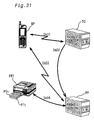
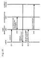
Fig. 31 shows connection in the case of printing tickets via the print
portal;
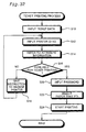
Fig. 32 is a flowchart showing a ticket printing process executed by
the print portal;
Fig. 33 shows connection in the case of printing user's own
documents via the print portal;
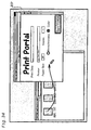
Fig. 34 illustrates an exemplified interface in the process of printing
user's own documents;
Fig. 35 shows connection in the case of printing electronic
newspapers via the print portal;
Fig. 36 shows connection in the case of printing electronic
newspapers in a place of accommodation;
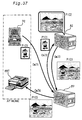
Fig. 37 shows connection in the case of printing processed data;
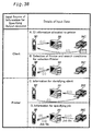
Fig. 38 enumerates various processes of designating a printer;
Fig. 39 shows a concrete example of Case C;
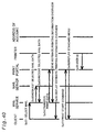
Fig. 40 shows a sequence of printing in Case C;
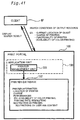
Fig. 41 shows functional blocks and data transmission relating to
the search for the output resource;
Fig. 42 shows functional blocks involved in the process of addition of
input source ID information;
Fig. 43 is a flowchart showing a routine of adding input source ID
information;
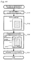
Fig. 44 is a flowchart showing a modified routine of adding input
source ID information;
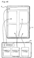
Fig. 45 shows functional blocks involved in the layout printing;
Fig. 46 shows an overview of the layout functionality;
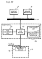
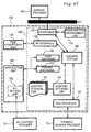
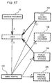
Fig. 47 shows functional blocks involved in the process of addition of
ad;
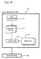
Fig. 48 shows the functions of the respective functional blocks in the
process of addition of ad;
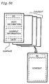
Fig. 49 is a flowchart showing a routine of addition of ad;
Fig. 50 shows examples of addition of ad;
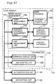
Fig. 51 shows functional blocks to attain customization;
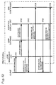
Fig. 52 is a time chart in the process of printing mails in a
customized environment;
Fig. 53 shows an example of customized interface;
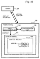
Fig. 54 shows data transmission in the process of registering the
customized information;
Fig. 55 shows functional blocks involved in the document storage
functionality;
Fig. 56 shows data transmission in the process of printing a
registered content;
Fig. 57 is a timing chart in the process of printing the registered
content;
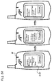
Fig. 58 shows an exemplified interface in the process of printing the
registered content;
Fig. 59 shows data transmission in the process of adding a content;
Fig. 60 is a time chart in the process of adding a content;
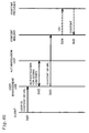
Fig. 61 is a time chart in the process of deleting a content;
Fig. 62 shows functional blocks in a modified example to attain the
contents registration functionality;
Fig. 63 shows data transmission in the process of registering
customization information;
Fig. 64 is a time chart in the process of printing a mail under the
customized conditions;
Fig. 65 shows data transmission in the process of registering
customization information;
Fig. 66 is a flowchart showing a routine of setting the printing
conditions;
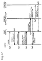
Fig. 67 shows the flow of accounting;
Fig. 68 shows a process of collecting charges at a printing station
70A;
Fig. 69 shows a process of collecting charges at the print portal;
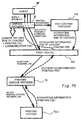
Fig. 70 shows a process of collecting charges at a service provider;
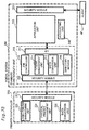
Fig. 71 shows objects and methods of authentication;
Fig. 72 shows functional blocks to attain the maintenance and
management functionality;
Fig. 73 shows functional blocks to mediate printing via a single-layer
server; and
Fig. 74 shows possible extension of the system utilizing the single-layer
server.
Best Modes of Carrying Out the Invention
Some modes of carrying out the invention are discussed below in the
following sequence:
A. Basic System Architecture
A1. Overview of System
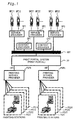
Fig. 1 illustrates the general architecture of a printing system.
This embodiment regards the system that executes printing via the Internet.
The similar architecture may be applicable to a relatively limited network
environment, such as a LAN (Local Area Network) or computer
communication.
In the system of this embodiment, a diversity of servers and clients
are connected to the Internet INT. For convenience of explanation, the
connection is shown in a hierarchical manner, but the respective
constituents enable mutual transmission of information via the Internet
INT. For clarity of illustration and explanation, only a limited number of
constituents are shown, although there is no limit of in number of
connections. The technique of the embodiment executes a printing
operation with an arbitrary printer under the system architecture including
a large number of servers and clients connected with one another via the
Internet INT.
This embodiment uses, as the clients, mobile phones MP11, MP12,
MP21, MP22, MP31, MP32 having the access functionality to the Internet.
Each of these mobile phones, for example, MP11 gains access to the Internet
via any of service providers SP1, SP2, and SP3. The clients are not
restricted to the mobile phones but may be personal computers.
Content providers CP1 and CP2 are also connected to the Internet
INT. In the system of this embodiment, these content providers, for
example, CP1, provide contents to be printed. The content providers
include Web page providers on the Internet INT.
In the system of this embodiment, printing stations, for example,
PS11, are output resources. The printing stations like PS11 represent
printers that enable transmission of data via the Internet. The printing
station is constructed, for example, by combining a computer connected to
the Internet with a printer locally connected to the computer. The printing
stations may be located in rather private spaces with relatively limited
users like individual houses and offices or in rather public spaces like stores
and hotels.
In the system of this embodiment, in response to an instruction from
the client MP11, contents provided by the content provider CP1 are
transmitted to the printing station, which executes an actual printing
operation. Two different-layered servers, that is, upper-layer and lower-layer
servers, mediate data between the clients and the printing stations.
In the illustrated example, the upper-layer server is a printing
mediation system (print portal) PP, and the lower-layer servers are printing
service providers PSP1 and PSP2.
The lower-layer servers, such as the printing service provider PSP1,
function to manage the printing stations like PS11. In the illustrated
example, the printing service provider PSP1 manages printing stations
PS11 to PS14, whereas the printing service provider PSP2 manages printing
stations PS21 to PS24. In the case where the printing stations like PS11
are located in individual stores, for example, the respective printing service
providers PSP1 may be owned by different business proprietors. A
business proprietor A owns the printing service provider PSP1 and manages
the printing stations PS11 to PS14 located in its head quarter and branch
shops. A business proprietor B owns the printing service provider PSP2
and manages the printing stations PS21 to PS24. Such arrangement
enables each business proprietor to manage its own printing stations and
supply unique services relating to the mediation of print data, for example,
discount service.
The upper-layer server, that is, the print portal PP, manages the
printing service providers PSP1 and PSP2. The print portal PP thus
indirectly manages the printing stations like PS11 via the printing service
providers PSP1 and PSP2. The upper-layer server provides common
functionality even when the printing service providers PS1 and PS2 are run
by the different business proprietors. For example, the upper-layer server
provides a standard interface in response to a print request from the client
MP11. This desirably enhances the utility of the users.
The upper-layer server and the lower-layer server are functionally
parted from each other, and each server may not be constructed as a single
server. The functionality of the upper-layer server and the lower-layer
server discussed below may be distributed into multiple servers.
A2. Functionality
The internal structure of each constituent included in the system of
the embodiment will be discussed later. In order to elucidate the
functionality of the servers and the other constituents, the following
description regards a concrete example of printing E mails utilizing the
print portal.
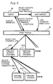
Fig. 2 shows flow of data in the process of printing E mails. Fig. 3
is a time chart in the process of printing E mails. Fig. 4 shows an
exemplified interface in the process of printing E mails. The functionality
of the respective units is discussed with referring to these drawings. In
the case of E mails, a mail service CP corresponds to a content provider.
The user first gains access from a client MP to the mail service CP,
checks E mails addressed to the user, and selects one or plural mails to be
printed. A series of interface windows appearing on a display unit DISP of
the mobile phone is shown in Fig. 4. The left-side window shows that there
are four mails Mail 1 to Mail 4 addressed to the user and that Mail 2 and
Mail 4 have been selected as objects of printing. This interface is provided
by the mail service CP. When the user presses a button 'iPrint' on the
window, a requirement for execution of printing is transmitted from the
mail service CP to the print portal PP (see Sa01 in Fig. 3 and Fig. 2).
When the mail service CP is registered in advance as a content
provider in the print portal PP, the button 'iPrint' appears on the window.
This button functions as a link to the print portal PP. In response to the
requirement for printing by a press of the 'iPrint' button, the destination of
access by the client MP is changed to the print portal PP. Print data, that
is, data of Mail 2 and Mail 4, is then transmitted from the mail service CP to
the print portal PP (see Sa02 in Fig. 3 and Fig. 2).
The print portal PP subsequently provides the client MP with
interfaces for specifying the output resource and printing conditions (see
Sa03 in Fig. 3 and Fig. 2).
The center drawing of Fig. 4 shows an interface window for
designating the output resource. Available printing stations are
enumerated for the designation of the output resource. The list of the
available output resources may be displayed in a hierarchical manner. For
example, when the user selects 'XX Store' in the list shown in Fig. 4, all
shops belonging to the XX Store chain are enumerated. One modified
procedure may cause the use to select one among available printing service
providers on the first stage of the hierarchical designation.
The right-side drawing of Fig. 4 shows an interface window for
specifying the printing conditions. Typical examples of the printing
conditions include the paper size, the layout, and the resolution. Selection
of a 'Printing Paper' menu enables the detailed settings for the printing
paper, for example, the size A4 or B5. Selection of a 'Layout' menu enables
the detailed settings for the layout, for example, 1 page /sheet or 2 pages
/sheet. Selection of other menus enables the detailed settings for other
printing conditions. The settings of printing are not restricted to this
example, but a diversity of fields may be provided by taking into account the
utility.
When the user completes the specification of the output resource
and the printing conditions with the above interface, the specified
information is transmitted to the print portal PP (see Sa04 in Fig. 3 and Fig.
2). The print portal PP selects the printing service provider PSP1 as the
destination of transmission of a print job, based on the received information,
and transfers the print job to the selected printing service provider PSP1
(see Sa05 in Fig. 3 and Fig. 2). Here the printing service provider PSP1,
which manages the printing station PS11 designated by the user as the
output resource, is selected as the destination of transmission of the print
job.
The printing service provider PSP1 that has received the print job
selects the printing station PS11 and transfers the print job to the selected
printing station PS11 (see Sa07 in Fig. 3 and Fig. 2). Here the printing
station PS11 designated by the user is selected as the destination of
transmission.
The print data is converted to a PDF file, which is a general purpose
format, in the course of mediation with the print portal PP and the printing
service provider PSP1. The printing station PS11 analyzes the PDF file
and executes a printing operation.
As shown by Sa06 in Fig. 3, a display including the designated
output resource and the specified printing conditions may be given to the
client MP for the purpose of check and confirmation, prior to the transfer of
the print job from the printing service provider PSP1 to the printing station
PS11.
On completion of the printing operation, a report of printing results
may be transmitted from the printing station PS11 to the print portal PP.
The print portal PP detects the normal completion of the printing operation
based on the report, and carries out post services like accounting.
The above example mediates printing with the two different layered
servers, that is, the print portal PP as the upper-layer server and the
printing service providers like PSP1 as the lower-layer servers.
The use of the two-layered servers for the mediation have
advantages discussed below.
The lower-layer server may be organized by each business line, in
order to provide unique services characteristic of the business line and
allow discrimination from other business proprietors. Each business
proprietor can rather readily take in the users and the content providers
registered with the print portal PP as the potential customers of its
business line.
Even when the lower-layer servers are individually organized by
different business lines, the upper-layer server provides the users with a
standard interface. This enhances the utility of the print portal.
The user who has been registered with the print portal PP can
readily utilize a diversity of lower-layer servers under the control of the
print portal PP. This arrangement does not require time-consuming,
complicated registration and other related work for each lower-layer server,
thus enhancing the utility. The content providers share such advantages.
The content provider that has been registered with the print portal PP can
readily increase in number the users and the output resources of the offered
contents.
The printing mediation system is not restricted to the construction
utilizing the two-layered servers, but may be organized by a single-layer
server configuration having the combined functions of the print portal and
the printing service providers. This configuration is discussed later as a
modified example of the embodiment.
A3. Configuration of Functional Blocks
Fig. 5 shows functional blocks of the print portal. For convenience
of explanation, the respective constituents are expressed by numbers
different from the symbols of Fig. 1, although the constituents of the
identical names have the same functions.
As illustrated, a print portal 100 mainly includes three functional
blocks, a core module 130, a file conversion unit 110, and an application unit
180. In this embodiment, these functional blocks are attained by the
software.
The file conversion unit 110 converts the format of print data to a
predetermined intermediate file in the course of mediation of the print data.
The PDF is used as the general purpose format in this embodiment.
The application unit 180 executes the main functions of the print
portal PP to mediate the print data and a diversity of additional functions.
The additional functions include, for example, addition of advertisement
(ad) and accounting, which will be discussed later.
The core module 130 cooperates with the file conversion unit 110
and the application unit 180 to mediate the print data. The core module
130 takes charge of communication with a content provider 10, a service
provider 30, and a printing service provider 50. The printing service
provider 50 has an interface module 52 to ensure the flexibility of a protocol
in connection with the print portal PP.
Fig. 6 illustrates the internal structure of the core module 130.
This internal structure is only illustrative, and the core module 130 may
have any of other diverse constructions.
A controller 132 controls the operations of the respective functional
blocks of the print portal 100 and transmission of information to and from
the outside via the internet INT. The control includes registration and
management of users and providers, control of the status of print jobs,
acceptance and cancellation of print requests, and retrieval of printers as
the output resource. The controller 132 also provides an interface window
to allow transmission of data between the print portal 100 and the outside.
A registration management unit 134 takes charge of registration
and management of the user utilizing the print portal PP, the content
provider 10, and the printing service provider 50. The registration
management unit 134 creates an interface window for the registration and
management and stores and updates registration-related data in a
predetermined data base.
A queuing system 140 relays the operations of the respective
functional blocks. In this embodiment, the respective functional blocks are
constructed by the object-oriented software. Each functional block refers
to a message registered in the queuing system 140, detects the presence of a
job to be processed, and executes the actual processing. On completion of
the processing, a message representing conclusion of the processing is
registered in the queuing system 140. The respective functional blocks
execute the processing with the queuing system 140 as the relay. The print
portal PP accordingly actualizes a series of processing, from acceptance of a
print request to completion of a printing operation.
In order to attain the series of processing, the queuing system 140
has a content fetching queue, a file conversion queue, a job sending queue,
and a job canceling queue.
A content fetching unit 160 gains access to the content provider 10
and fetches a content specified by the user as an object of printing. The
fetched content is temporarily stored in a content storage unit 162. The
content fetching unit 160 refers to the content fetching queue provided in
the queuing system 140 and performs the above operation according to the
message accumulated in the content fetching queue. After fetching the
content, the content fetching unit 160 registers a message to require file
conversion of the content in the fine conversion queue provided in the
queuing system 140.
The file conversion unit 110 functions to convert the content to the
PDF format. The PDF is the general purpose format. Conversion of the
print data to this format advantageously enables output of the print data to
a diversity of printers. Another advantage is relatively accurate
reproduction of the selected layout in prints. The PDF allows conversion
from practically any print data including documents and pictures, so that a
wide range of contents can be the object of printing. A page description
language, such as Postscript (registered trademark), may alternatively be
used as the general purpose format.
In the structure of this embodiment, with a view to relieving the
load applied to each server, the file conversion unit 110 is constructed as a
separate server from the core module 130. The core module 130
accordingly has a DF interface 136 to allow transmission of data to and from
the file conversion unit 110.
The DF interface 136 transfers data to the file conversion unit 110,
in response to the message accumulated in the file conversion queue
provided in the queuing system 140. When receiving a processed PDF file
from the file conversion unit 110, the DF interface 136 registers a message
of print job transmission in the job sending queue provided in the queuing
system 140. One possible modification omits the DF interface 136 and
constructs the file conversion unit 110 to gain direct access to the queuing
system 140.
A PSP interface 138 functions to transmit a print job to the printing
service provider 50. More specifically, the PSP interface 138 transmits a
print job to the designated printing service provider 50, in response to the
message accumulated in the job sending queue provided in the queuing
system 140. The PSP interface 138 also sends a message of job
cancellation accumulated in the job canceling queue. The transmission is
attained according to a diversity of protocols set by the printing service
provider 50, for example, HTTP (Hypertext Transport Protocol).
The core module 130 includes a diversity of databases, such as a
user database 150 and a printer database 152. Although only two
databases are illustrated in this embodiment, a greater number of
databases may be provided in the core module 130. The registration
management unit 134 manages these databases. The databases are
utilized for the processing executed in the core module 130, as well as for
the processing executed by the application unit 180.
Fig. 7 shows the overview of the user database 150. The user
database 150 includes files provided for the respective users of the print
portal 100. Each file stores user-related attribute information, for
example, the user name, the ID number, the available printing service
providers (PSPs) with authentication for access, the accounting policy, the
settlement policy, and the settlement information. The information on the
accounting policy shows selection of the charge system, for example, a fixed
rate system or a page rate system. The information on the settlement
policy specifies, for example, credit card settlement. The settlement
information represents each user's account and current settlement status.
Various pieces of information other than those mentioned above may also be
registered in the user database 150.
Fig. 8 shows the overview of the printer database 152. Like the
user database 150, the printer database 152 manages a diversity of
attribute information with regard to the respective printers. In this
embodiment, the printer name, the ID number, and the authorized users
with authentication for access are some registered pieces of information.
The ID number represents an index utilized to identify the printer in the
printing process with the print portal 100. The printer database 152 also
stores information on the performances of each printer, for example, the
availability of color printing, the printable paper size, and the printing rate.
Various pieces of information other than those mentioned above may also be
registered in the printer database 152. In the structure of this
embodiment, the printer database 152 stores the information by the unit of
printing stations. The printer database 152 may alternatively store the
information by the unit of printing service providers.
As described above, the series of processing is executed in the print
portal 100, based on the messages registered in the queuing system 140.
The functions of the queuing system 140 are discussed concretely with the
example of the printing operation shown in Figs. 2 to 4.
Fig. 9 is a time chart of the processing via the queuing system 140.
The user presses the 'iPrint' button to send a print request (step Sb01) on
the interface provided by the content provider. The content provider
receives the print request and transmits the URL (Uniform Resource
Locator) of a content to be printed and the user ID to the controller 132 in
the print portal 100 (step Sb02). The controller 132 provides the user with
an interface for specifying the printing conditions (step Sb03). When the
user sets the printing conditions on the interface (step Sb04), the controller
132 registers a message representing acceptance of the print request in the
queuing system 140 (step Sb05), in response to the setting of the printing
conditions. This concludes the process of accepting the print request.
The print portal 100 then fetches the content specified by the print
request. This content fetching process is carried out in parallel to the
print request acceptance process. The content fetching unit 160 refers to
the queuing system 140 at regular intervals and picks up a message
accumulated therein (step Sb10). The content fetching unit 160 gains
access to the content provider according to the picked-up message (step
Sb11) and fetches the specified content (step Sb12). On completion of
fetching the content, the content fetching unit 160 registers a message
representing conclusion of the content fetching process in the queuing
system 140 (step Sb13). This concludes the process of fetching the content.
The print portal 100 subsequently carries out file conversion of the
content. This file conversion process is carried out in parallel to the print
request acceptance process and the content fetching process. The DF
interface 136 refers to the queuing system 140 at regular intervals and
picks up a message accumulated therein (step Sb21). The DF interface 136
causes the file conversion unit 110 to carry out the file conversion according
to the picked-up message. On completion of file conversion, the DF
interface 136 registers a message representing conclusion of the file
conversion in the queuing system 140. This concludes the process of file
conversion.
The print portal 100 then transmits the print job to the printing
service provider. The transmission is carried out in parallel to the above
processes. The PSP interface 138 refers to the queuing system 140 at
regular intervals and picks up a message accumulated therein (step Sb23).
The PSP interface 138 sends the print job to the designated printing service
provider according to the picked-up message (step Sb24). This concludes
the process of sending the print job.
As discussed above, the print portal 100 implements the four
processes to accept the print request, fetch the content, convert the file, and
send the print job in the course of mediation of printing. With regard to
each print job, these processes are performed in sequence. The respective
functional blocks, however, do not perform the processing in a synchronous
manner. In the print portal 100, the respective functional blocks execute
the individual processes at intrinsic timings, while the queuing system 140
relays these processes to actualize a series of processing as a whole.
In this embodiment, the use of the queuing system 140 ensures the
excellent extensibility.
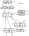
Fig. 10 shows possible extension of the system. As illustrated,
arbitrary numbers of the controllers 132, the content fetching units 160, the
DF interfaces 136, and the PSP interfaces 138 are connectable via the
queuing system 140. The respective units may be constructed by different
servers. In the case where the structure has multiple controllers like
controllers 132 and 132A, it is desirable to provide a load distribution unit
102 as a single interface with the outside. The load distribution unit 102
accepts print requests and selectively uses the controllers 132 and 132A by
taking into account the current loading applied to the controllers 132 and
132A.
In the structure of this embodiment, the respective functional blocks
independently execute the processing, based on the messages accumulated
in the queuing system 140. This arrangement ensures easy extension of
the system. The example of Fig. 10 multiplies all the functional blocks.
The extension of the system can be actualized flexibly according to the
loading applied to the respective functional blocks.
The example of Fig. 10 shows the extension of the system in the core
module 130. Similar extension of the system may be applied for the file
conversion unit 110.
Fig. 11 shows possible extension of the file conversion unit. This
example includes multiple file conversion units 110 and 110A provided via
the queuing system 140. These file conversion units 110 and 110A may be
constructed by different servers, with a view to relieving the load.
In the example of Fig. 11, there are the multiple controllers 132 and
132A and content fetching units 160 and 160A.
File conversion Web servers 104 and 104A are also provided as
additional functional blocks. The file conversion Web servers 104 and
104A carry out only the file conversion, regardless of the mediation of
printing. Namely the file conversion Web servers 104 and 104A are not the
essential functional blocks for the mediation of printing.
The user sends either a print request or a file conversion
requirement to the load distribution unit 102. The load distribution unit
102 transmits the print request to either one of the controllers 132 and
132A, while transmitting the file conversion requirement to either one of
the Web servers 104 and 104A. In the case of the file conversion
requirement, the content as the object of conversion is transmitted together
with the requirement.
The controllers 132 and 132A register the print request in a content
fetching queue 144. The content fetching units 160 and 160A fetch a
content according to the registered message and register a message of
requiring file conversion in a file conversion queue 142. The file
conversion Web servers 104 and 104A are not required to fetch a content
and thus directly register a message of requiring file conversion in the file
conversion queue 142.
The file conversion units 110 and 110A individually refer to the file
conversion queue 142 and execute the processing in response to a message
registered therein, if any. The individual operations of the two file
conversion units 110 and 110A enable distribution of the loading of file
conversion.
The examples of Figs. 10 and 11 extend the system utilizing a single
queuing system 140. Providing multiple queuing systems 140 in parallel
allows greater-scaled system extension.
A4. Connection with Printing Service Provider
Fig. 12 shows interfaces with the printing service providers. As
mentioned previously, the printing service providers are managed by
different business proprietors from that of the print portal 100. The
different printing service providers may accordingly have different
requirements of the protocol for mediation with the print portal 100. In
this embodiment, the PSP interface is structured to accept diverse
protocols.
As illustrated, the PSP interface 138 has two-layered interfaces.
The upper-layer interface is a general purpose PSP interface 139. The
general purpose PSP interface 139 transmits messages and data to and from
other functional blocks, such as the queuing system 140, included in the
print portal 100.
The lower-layer interface includes individual PSP interfaces 138a,
138b, and 138c. The individual PSP interfaces like 138a are provided for
the respective printing service providers, and transmit data to and from the
general purpose PSP interface 139 according to protocols adequate for the
respective requirements.
In one example, the individual PSP interface 138a communicates
with the printing service provider 50a by SMTP (Simple Mail Transfer
Protocol) for both sending and receiving. The individual PSP interface
138b communicates with the printing service provider 50b by HTTP for both
sending and receiving. The individual PSP interface 138c transmits data
to the printing service provider 50c by HTTP, while receiving data from the
printing service provider 50c by FTP (File Transfer Protocol). The
individual PSP interfaces may transmit data by diverse protocols other
than those discussed above, according to requirements of the printing
service providers.
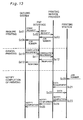
Fig. 13 shows flow of data between the print portal and the printing
service provider in the printing process. In the print portal 100, on
conclusion of the processes of fetching the content and converting the file, a
message of requiring job transmission is registered in the queuing system
140. This message is equivalent to a print request sent to the printing
service provider.
The PSP interface 138 monitors the queuing system 140 at regular
intervals and picks up a print request (step Sc01). The PSP interface 138
then transmits the print request to the printing service provider designated
by this message (step Sc02). The printing service provider sends a job
number as the response (step Sc03), and the PSP interface registers the job
number in the queuing system 140 (step Sc04). In this example, the
printing service provider temporarily holds the print request. One
possible modification omits the transmission of the job number and causes
the printing service provider to directly transmit the print request to the
designated printing station.
When the user gives an instruction to cancel the printing operation,
data transmission is carried out in a similar manner. In response to
registration of a cancellation requirement in the queuing system 140, the
PSP interface picks up the cancellation requirement (step Sc10) and
transmits the cancellation requirement to the printing service provider
(step Sc11). The printing service provider sends a response message (step
Sc12), and the PSP interface registers the response message in the queuing
system 140 (step Sc13). The transmission of the message of canceling the
printing operation is carried out in parallel to the transmission of the print
request.
In the example of Fig. 13, the printing operation is executed in
response to input of the job number into the printing station. The user
inputs the job number through an operation of, for example, a panel, on the
printing station (step Sc20). The printing station accordingly requires the
printing service provider to send data (step Sc21), receives the required
data (step Sc22), and carries out an actual printing operation. On
completion of the printing operation, the printing station sends a
notification representing conclusion of the printing operation to the
printing service provider (step Sc23). The notification is registered in the
queuing system via the PSP interface (steps Sc24 and Sc25).
In response to detection of the concluded printing operation, the
print portal 100 notifies the user of completion of the printing process,
deletes various data relating to the concluded job, and carries out post
services like accounting.
A5. Print request
As discussed previously with Figs. 2 to 4, in this embodiment, the
printing process starts in response to a click of the 'iPrint' button displayed
on the window of the client. At the starting time, the destination of
access by the client is changed from the content provider, which provides a
content to be printed, to the print portal, and information representing the
address of the content is transferred from the content provider to the print
portal. The following describes transmission of data between the client,
the content provider, and the print portal at the starting time of the
printing process.
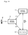
Fig. 14 shows the state of communication between the content
provider, the service provider, and the print portal. The procedure of this
embodiment is on the premise that these three entities are mutually
communicable. The service provider 30 communicates with the content
provider 10 and the print portal 100 by HTTP, whereas the content provider
10 communicates with the print portal 100 by HTTP, HTTPS, and FTP.
The applicable protocols are not restricted to this example.
Fig. 15 shows a procedure of issuing a print request. In this
example, on the window sent from the content provider 10 to the client MP
(Pr1), the 'iPrint' button is linked with the URL of the print portal 100. A
click of this button changes the destination of access by the client MP is
changed to the print portal 100 (Pr2). At this moment, the content
provider 10 transmits content information, which is required for execution
of the printing operation, as a parameter to the print portal 100.
One exemplified procedure of transmitting the content information
provides a CGI (Common Gateway Interface) called on a click of the 'iPrint'
button and utilizes a method like GET/POST to send the content
information to the print portal.
The transmitted content information includes, for example, the URL
and the name of the content. By taking into account the possible
restriction on the settings of printing with regard to each content set by the
content provider 10, the content information may further include the paper
size, the selection of color printing or monochromatic printing, the
maximum copies permitted, the permission to contract, the requirement of a
notice to inform the content provider 10 of completion of printing, and the
price of the content.
Fig. 16 shows another procedure of issuing the print request. In
this example, on the window sent from the provider 10 to the client MP
(Pr11), a printing request from the client MP is sent to the content provider
10 (Pr12) in response to a click of the 'iPrint' button, and the content
provider 10 changes over the connection of the client MP to the print portal
100 (Pr13) by the function of redirecting. Simultaneously with the
redirecting operation, the content provider 10 transmits the content
information to the print portal 100.
Either of these procedures may be adopted to issue the print
request.
There are a diversity of interface windows applicable to issue the
print request.
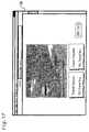
Fig. 17 shows an interface window applied to issue the print request.
This interface is used when the user gains access from the personal
computer to a Web page. In this case, the provider of the Web page
corresponds to the content provider. As in the example of Fig. 4, the
'iPrint' button for issuing the print request is set on the Web page provided
by the content provider. Either of the procedures discussed above with
Figs. 15 and 16 may be applied for data transmission in response to a click
of this button.
Fig. 18 shows another interface window applied to issue the print
request. In this example, the Web page is not required to include any extra
button. The browser provides this window when the personal computer is
the client. The window displays a Web page of a tourist agency including a
travel coupon and a favor voucher. When there is any printer locally
connected to the computer PC, the user clicks the 'Print' command in the
pull-down menu 'File' for execution of the printing operation. In this
example, the print request is issued on the similar interface.
When the user clicks the menu name 'File' on the menu bar, a pull-down
menu including commands like 'New' and 'Open' appears. The pull-down
menu includes the 'iPrint' command as the function of the browser. A
user's click of the 'iPrint' command issues the print request. The function
of notifying the browsed content provider of selection of the 'iPrint'
command is provided in advance in the browser. This actualizes the data
transmission shown in either Fig. 15 or Fig. 16. The print portal may
provide the browser with an additional module to attain the function.
Fig. 19 shows still another interface window applied to issue the
print request. In the above examples, the content provider, which provides
a content to be printed, is linked with the print portal. In this example, on
the other hand, the user gains access to a Web page provided by the print
portal and identifies the address of a desired content. In the case where
the Web page of the print portal is displayed by the link from an original
Web page, which is the object of printing, the URL of the original Web page
may be displayed as default information in a specific field of the print data.
The Web page of the print portal has an input box for specifying a
printer as the output resource. A diversity of methods may be adopted to
specify a printer as the output resource. The window of this example
allows selection of a printer in a printer list.
When the user clicks a dialog box for specifying the printer, a first
pull-down menu includes relatively wide districts, for example, Aichi Pref.,
Gifu Pref., and Nagano Pref. When the printer of the desired output
resource is located in Aichi Prefecture, the user clicks 'Aichi Pref.' A
second pull-down menu then appears to include relatively narrow regions in
Aichi Prefecture, for example, 'Kita Ward, Nagoya City' and 'Nishi Ward,
Nagoya City'. When the user clicks 'Naka Ward, Nagoya City' where the
printer of the desired output resource is located, the exact locations of all
the available printers registered in the print portal service PS are displayed.
The user selects the name of the hotel where the user stays, so as to specify
the printer PRT of the desired output resource. This arrangement enables
a desired printer to be readily selected among available printers by the
hierarchical selection.
After specifying the printing conditions including the address of the
print data and the desired output resource, the user clicks the 'iPrint'
button to issue the print request.
A6. File Conversion
Fig. 20 shows data transmission between the core module 130 and
the file conversion unit 110. The DF interface 136 is omitted from the
illustration, with a view to avoiding the non-required complication.
As mentioned previously, the content to be printed is converted to
the general purpose format by the file conversion unit 110. In this
embodiment, PDF is applied for the general purpose format. The file
conversion unit 110 works according to the messages registered in the
queuing system 140. The configuration of this embodiment enables
communication between the core module 130 and the file conversion unit
110 and file conversion to be executed at different timings. Such
configuration ensures smooth processing even in the case of concentration
of many file conversion requirements. Another applicable configuration
maintains the communication until the file conversion executed by the file
conversion unit 110 is completed.
As illustrated, when the file conversion process starts, a request of
file conversion is sent from the core module 130 to the file conversion unit
110. In the configuration of this embodiment, the request is transmitted
by the protocol HTTP. The request accordingly has an HTTP header and
an HTTP body, which includes a command part and a file part. The
command part includes a command for controlling the state of file
conversion, and the file part includes a content as the object of file
conversion.
The file conversion unit 110 temporarily holds the request and sends
a return value, which represents acceptance of the request, to the core
module 130. Then the communication between the core module 110 and
the file conversion unit 110 is suspended. Meanwhile the file conversion
unit 110 may receive another request.
The file conversion unit 110 executes file conversion at a
predetermined timing in response to the request, and transfers the result of
the file conversion as a reply to the core module 130. In the configuration
of this embodiment, the transfer of the file conversion result utilizes a
POST command based on the HTTP protocol. In order to enable the
transfer utilizing the POST command, the core module 130 is constructed to
function as an HTTP server 131. The file conversion unit 110 transmits
the replay to the URL specifying the HTTP server 131. The replay has an
HTTP header and an HTTP body, which includes a status part and a file
part. The status part includes information representing the state of
execution of the file conversion job, such as 'completion of conversion'.
When the status part includes 'completion of conversion' information, the
result of the file conversion is attached to the file part. In the case of any
failure of conversion, the status part includes 'error' information. In the
case of a replay to the inquiry about the status from the core module 130,
the status part includes 'stand-by' information.
The file conversion unit 110 executes the acceptance of the request
and the transfer of the file conversion result at different timings. This
enhances the rate of file conversion. The file conversion unit 110 posts the
file conversion result to the core module 130, so that the core module 130 is
free from the process of actively fetching the file conversion result. This
arrangement advantageously relieves the load of the core module 130.
A diversity of procedures other than that discussed above may be
applied to transfer the file conversion result from the file conversion unit
110 to the core module 130.
In one modified example, the core module 130 provides an internal
mail server, and the file conversion unit 110 sends the file conversion result
in the form of a mail to this mail server.
In another modified example, the core module 130 carries out
polling for the completion of the file conversion executed by the file
conversion unit 110 according to the following procedure. The core module
130 gives an inquiry about the status of the file conversion job to the file
conversion unit 110 at regular intervals. When the job is incomplete, the
return value representing the incomplete state is sent to the core module
130. When the job is complete, on the other hand, the result of the file
conversion is sent to the core module 130. This application requires the
core module 130 to take the load of polling, but facilitates mounting of the
file conversion unit 130.
The communication between the file conversion unit 110 and the
core module 130 may be kept over the whole time period from the
acceptance of the request to the completion of the file conversion. Another
possible application estimates a time required for file conversion based on
the file size, and changes the replay timing of the conversion result
according to the estimation. When the estimation result requires a
relatively long time, the timing of the replay is differentiated from the
timing of the registration of the request. When the estimation result
requires a relatively short time, on the other hand, the result may be
transmitted as the return value to the registration of the request.
In this embodiment, the file conversion unit 110 is organized inside
the print portal 100. The file conversion unit 110 may execute the file
conversion in a variety of phases of mediating the print data. Fig. 21
shows variations on timing of file conversion.
Four cases, Case A to Case D, are shown here. For convenience of
explanation, original data before file conversion is called 'content', and
converted data after file conversion is called 'PDF data'.
In Case A, the content provider carries out file conversion. When
the user sends a self-made document from the client to the print portal, the
client simultaneously corresponds to the content provider. In Case A, the
content provider outputs data in the form of a PDF file. Neither the print
portal nor the printing service provider is required to carry out the file
conversion.
In Case B, the print portal carries out file conversion. This
corresponds to this embodiment. The content transmitted to the print
portal in Case B may follow any of diverse formats, for example, HTML,
XML, text file, JPEG. The data output from the print portal to the
printing service provider are unified to the PDF file.
In Case C, the printing service provider carries out file conversion.
Data of various formats are supplied from the content provider to the
printing service provider via the print portal, and are unified to the PDF
file immediately before transmission to the printing station. As the
printing service provider is individually organized by each business
proprietor, the business proprietor may individually select the format after
the file conversion.
B. Examples of Printing
A variety of examples utilizing the system of the embodiment are
discussed below.
B1. Printing Mails
Fig. 22 shows connection in the case of printing E mails. In this
example, the user operates a mobile phone MP having the function of access
to E mails and causes selected E mails, which are addressed to the user, to
be printed. A printer PRT is located in a public space, for example, in a
store like a convenience store, a hotel, or a public hall. This system is
especially effective for printing various data with a printer located in the
public space. The system may alternatively utilize the printer that is
under the user's control, for example, at home or in an office. The mobile
phone MP corresponds to the client, a mail service RM and a mail server MS
correspond to the content providers, and the printer PRT corresponds to the
printing station. The printing service provider is omitted from the
illustration.
The printer PRT functioning as the output resource is registered in
advance in a print portal PP and is identified by an ID number allocated
thereto. In this example, the printer PRT has the ID number '1111'. The
ID number is a code set by the print portal PP, irrespective of the
information for identifying the printer PRT on the network, for example, an
IP address used in the TCP/IP protocol or a URI code used in the IPP
protocol. As discussed later, in this example, the user specifies the printer
PRT of the desired output resource with this ID number. The arrangement
of setting no relation between the information for identifying the printer
PRT on the network and the ID number open to the general users enables
the address of the printer PRT on the network to be hidden from the public.
This effectively prevents unauthorized and illegal accesses.
The print portal PP, the mail service RM, and the mail server MS
may be provided by different business proprietors, as long as they are
mutually connected. For example, the mail server MS is registered in the
mail service RM, which is registered in the print portal PP. The mail
service RM offers functions required for printing via the print portal PP as
one of the services. These functions include, for example, providing an
interface for issuing print requests to the print portal PP and transferring
contents to the print portal PP.
One concrete procedure of printing E mails is discussed below with
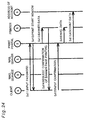
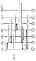
referring to Figs. 23 to 26. Figs. 23 and 24 show a sequence of printing E
mails. Figs. 25 and 26 show an exemplified interface in the process of
printing E mails.
The user gains access from the mobile phone MP to the mail service
RM (communication Cm1 in Fig. 22). The mail service RM then accesses
the mail server MS to fetch data regarding E mails addressed to the user,
and displays the data, such as 'where the mail is sent from' and 'subject', on
the mobile phone MP (communications Cm2 and Cm1 in Fig. 22). The user
selects desired E mails as the objects of printing out of the displayed list of
E mails and transmits the selected E mails to the mail service RM (see step
Sd01 in Fig. 23).
The left-side drawing of Fig. 25 shows an interface used for selection
of desired E mails. A list of E mails addressed to the user is displayed with
corresponding checkboxes on a display DISP of the user's mobile phone MP.
In this embodiment, there are four mails Mail 1 to Mail 4 addressed to the
user. The user operates a cursor key on the mobile phone MP to tick the
checkbox corresponding to each E mail of interest as the object of printing.
In this example, the user ticks two E mails, that is, Mail 2 and Mail 4. The
'iPrint' button is displayed together with the list of E mails. After ticking
the checkboxes corresponding to the E mails to be printed, the user shifts
the cursor to the 'iPrint' button and presses the 'iPrint' button to transmit
the selected E mails as the results of the selection to the mail service RM.
This interface is only illustrative. A diversity of other interfaces are
applicable, as long as the interface exerts the function of selecting desired E
mails as objects of printing among all the received E mails and the function
of transmitting the results of the selection to the mail service RM.
When receiving the results of the selection, the mail service RM
accesses the mail server MS and fetches data on the selected E mails (steps
Sd02 and Sd03 in Fig. 23). The mail service RM also fetches data of a file
attached to the E mail, if any.
The mail service RM then transfers the data on each E mail of
interest as the object of printing to the print portal PP through
communication Cm3 in Fig. 22 (step Sd04 in Fig. 23). The print portal PP
estimates the number of pages to be printed, the charge, and the required
time, based on the transmitted information, such as the quantity of print
data, and sends back the results of the estimation as an estimate printing
information overview to the mail service RM (step Sd05 in Fig. 23). At this
moment, the detailed conditions like the output resource and the print mode
have not yet been specified, so that the results of the estimation like the
charge and the required time include some errors. The data transferred
from the mail service RM at step Sd04 should be sufficient for specifying the
estimate printing information overview. It is accordingly not required to
transfer all the data of the E mail, but transmission of only the information,
such as the quantity of data of the E mail and the discrimination code
representing color or monochromatic, may be sufficient.
The mail service RM causes the estimate printing information
overview received from the print portal PP to be displayed on the mobile
phone MP (step Sd06 in Fig. 23). The right-side drawing of Fig. 25
illustrates a display example of the estimate printing information overview.
The number of pages to be printed, the charge, and the required time are
displayed for each designated E mail. Each field may show the total of all
the designated E mails. Fields other than those illustrated in Fig. 25 may
be included in the estimate printing information overview.
The user checks the displayed estimate printing information
overview and determines execution or non-execution of the printing
operation. When the printing operation is to be executed, the user gives a
print start command (step Sd07 in Fig. 23). The user presses an 'Execute'
button displayed on the display unit DISP with the estimate printing
information overview to give the print start command. The print start
command may alternatively be given by pressing any button originally set
on the mobile phone MP.
The print start command given by the user is transmitted to the
print portal PP via the mail service RM through communications Cm1 and
Cm3 in Fig. 22 (step Sd07 in Fig. 23). The print data, that is, the text of
each E mail and a file attached thereto, if any, is also sent from the mail
service RM to the print portal PP. When all the print data has already
been sent to the print portal PP at step Sd04, only the print start command
is transmitted here. In response to this command, the mail service RM
concludes the communication with the mobile phone MP. The subsequent
communication is communication Cm4 of Fig. 22 established between the
mobile phone MP and the print portal PP.
Receiving the print start command, the print portal PP causes a
standard menu of printing to be displayed on the mobile phone MP (step
Sd08 in Fig. 22). The left-side drawing of Fig. 26 illustrates a standard
menu. The standard menu includes fields for specifying the printing-related
conditions, such as the URL of a content of interest to be printed,
the number of copies, and the printer of the desired output resource.
Selection of a specific field out of this menu changes the display to an input
box. The example of Fig. 26 shows the case of specifying the printer of the
desired output resource. A box IP for inputting the ID number allocated to
the printer of the desired output resource appears in response to selection of
the field 'Printer No.' The user inputs the ID number '1111' allocated to
the printer PRT of the desired output resource in this box IP. When the
user specifies the printer of the desired output resource and presses a 'Send'
button, the input ID number is sent to the print portal PP to specify the
output printer (step Sd09 in Fig. 23). The other printing conditions, such
as the number of copies, are sent simultaneously.
Address information for locating the printer PRT of the desired
output resource on the network, for example, an IP address or a URI, has
been registered in advance in the printing service provide or in the print
portal PP. Information on the type of the printer like an inkjet printer or a
laser printer, as well as other required pieces of information have been
registered in the print portal PP. The print portal PP specifies detailed
estimate printing information based on the registered information and
causes the estimate printing information to be displayed on the mobile
phone MP (step Sd10 in Fig. 23).
It is desirable to display the ID number of the printer as the desired
output resource, together with the detailed estimate printing information.
The display effectively prevents the printing operation from being carried
out at any unintentional place, due to the user's input of a wrong ID
number.
The user confirms the detailed estimate printing information and
gives a print execution command (step Sd11 in Fig. 24). In this
embodiment, the user inputs a password assigned to the user, to give the
print execution command. The input of the password proves that the user
agrees with the specified printing conditions.
The center drawing of Fig. 26 shows an interface window for
inputting the password. After the display of the detailed estimate printing
information including the charge and the required time, the display is
changed to an input box for inputting the password. When the user inputs
the password and presses the 'Send' button, the input password is sent to
the print portal PP. Although the password is displayed as '****' in this
embodiment, the input password may be displayed explicitly.
The user password has been registered in advance in the print
portal PP. The print portal PP refers to the registered information and
verifies the identity of the logging-on user as an authorized user having the
right of access to the printer PRT. In the case of the authenticated user,
the display on the mobile phone MP is changed to a print start window (step
Sd12 in Fig. 24). Simultaneously, the print portal PP transmits preset
banner data to the printer PRT through communication Cm5 in Fig. 22 and
causes the printer PRT to print a banner ad (hereinafter referred to as the
banner page) (step Sd13 in Fig. 24).
The banner data may be kept in advance in the print portal PP or
may be sent from a specific content provider. With a view to saving the
resource, it is desirable to transfer the content and the banner data to the
file conversion unit 110 each time. The banner data is provided by diverse
sponsors that desire the use of the print portal PP. The display on the
mobile phone MP is then changed to a check window to request the user to
confirm successful printing of the banner page (step Sd14 in Fig. 24). The
right-side drawing of Fig. 26 shows an example of such display.
Printing the banner page has two major advantages discussed below.
The first advantage is to gain advertising rates from dealers, sales agents,
and traders that desire to advertise. This reduces the cost of the users
that utilize the print portal PP. The second advantage is test printing.
The banner page without any secrecy is printed first and the result of
printing is checked. This desirably prevents the wrong designation of the
desired output resource and the wrong settings of the printing conditions.
This is especially effective for printing documents with high secrecy.
The user confirms successful printing of the banner page and
presses an 'OK' button shown in Fig. 26 to notify the print portal PP of the
confirmation (step Sd15). The print portal PP sends data of all the
designated E mails to the printer PRT in response to the notification (step
Sd16 in Fig. 24). On completion of printing all the designated E mails, the
print portal PP outputs data regarding the total account of printing to the
address of account (step Sd17 in Fig. 24). This concludes the series of
processing.
A diversity of settings may be applied for the address of account.
In the case of charged mail service RM, the mail service RM may carry out
the accounting procedures. In this case, the account information is
transmitted to the mail service RM. The accounting procedures may also
be carried out by the carrier of the mobile phone MP, by the print portal, or
at the store or any other place where the printer PRT is located.
Figs. 27 to 29 show a sequence of printing E mails by a modified
procedure. This modified example shows the sequence including the
printing service provider. The printing service provider (PSP) not only
mediates data but carries out the processing related to the performances
and the status of the printer under control.
In this modified example, the print data is transmitted from the
mail service RM to the print portal at steps Sd01 to Sd04 discussed above.
The print portal outputs content information to the printing service
provider (step Sd41), in order to collect estimate printing information
overview. The printing service provider specifies the estimate printing
information overview based on the content information and sends back the
estimate printing information overview to the print portal (step Sd42).
The procedure subsequently carries out the series of processing in the same
manner as the above example, such as the display of the estimate printing
information overview on the mobile phone MP (steps st5 to st8). The print
portal may alternatively specify the estimate printing information
overview.
When the user designates the output printer (step Sd09), the print
portal outputs the content information and information regarding the
designation of the printer to the printing service provider (step Sd91), in
order to collect detailed estimate printing information. The printing
service provider checks the current status or working conditions of the
printer based on the received information (steps Sd92 and Sad93), specifies
detailed estimate printing information, and sends back the detailed
estimate printing information to the print portal (step Sd94). The check of
the working conditions determines whether the remains of expendables,
such as printing paper and toner set in the printer, are sufficient for
printing all the designated contents. When there is a fear of failure in
printing, for example, in the case of insufficient remains of the expendables,
a notice telling 'no printing due to insufficient expendables' is displayed on
the mobile phone MP.
When there is no fear of failure in printing, on the other hand, the
print portal displays the detailed estimate printing information, receives
input of the password, and displays the print start window (steps Sd10,
Sd11, and Sd12) and causes the printer to print the banner page. The
banner data is transmitted from the print portal to the printer via the
printing service provider (steps Sd131 and Sd132). The notification
showing completion of the printing operation is sent back to the print portal
via the inverse route (steps Sd133 and Sd134).
When the user confirms successful printing of the banner page in
response to the request from the print portal (steps Sd14 and Sd15), the
print portal starts printing the designated E mails according to the same
procedures as those of printing the banner page (steps Sd161 to Sd164).
On completion of printing, the print portal transmits the account data to
the address of account (step Sd17).
The two sequences of printing E mails discussed above are only
illustrative, and all the processing steps may not be essential. One
possible modification may omit the display of the estimate printing
information overview (steps Sd5 to Sd7 in Fig. 23) or printing of the banner
page (steps Sd12 to Sd15 in Fig. 24). Another possible modification may
allow the user to make a choice about printing the banner page.
B2. Printing Web Pages
Fig. 30 shows connection in the case of printing Web pages. In this
example, the user requires printing Web pages browsed on a mobile
computer PC, while there is no printer locally connected to the printer PC.
A printer located in the place of accommodation where the user stays is
utilized as the output resource. The same procedures may be adopted
when the user designates a printer under its own management, for example,
a printer located at home or in an office. The computer PC corresponds to
the client in this example, although the client may be a mobile phone.
The computer PC as the client, the printer PRT as the desired
output resource, the print portal PP, and a Web server WS providing data of
browsed Web pages are involved in this printing process. These
constituents are all connected to a network to allow mutual data
transmission. The printer PRT of the desired output resource is registered
in advance in the print portal PP.
The user downloads data from the Web server WS to the computer
PC through communication Cm21 in Fig. 30 and browses Web pages. The
user who requires printing the browsed Web pages gains access to the print
portal PP and causes the printing operation to be executed with the
designated printer PRT located in the place of accommodation.
The interface shown in Fig. 17, for example, may be utilized to issue
the print request.
The sequence of processing after the issuance of the print request
follows the sequence of printing E mails. The print portal PP causes the
computer PC to display printing information, input the password, and
confirm successful printing through communication Cm23. In response to
a print execution command, the print portal PP transmits banner data to
the printer PRT and causes the printer PRT to successively print the banner
page and designated Web pages through communication Cm24.
B3. Printing Tickets
The above examples use plain paper for printing. The following
describes the case of printing tickets as an example of restricting the
printing paper to special paper. The user gains online or offline access to a
ticket center and reserves a ticket, for example, for a concert. At this
moment, the user receives a reservation number from the ticket center.
The user accesses the ticket center again, identifies the reservation number,
and prints the ticket via the print portal. Printing on plain paper is
prohibited to guarantee the validity of the ticket. Namely printing is
restricted on specific paper exclusively provided for printing tickets. The
restriction is not changed by the user but is set by the ticket center TC.
Fig. 31 shows connection in the case of printing tickets via the print
portal. In this example, tickets are printed with a printer that is located
at a store and is available for printing tickets, in response to operations of
the mobile phone MP.
In the case of printing tickets, the mobile phone MP corresponds to
the client, the printer PRT corresponds to the printing station, and a ticket
center TC corresponds to the content provider.
The user gains access from the mobile phone MP to a Web page
provided by the ticket center TC through communication Cm31. The user
identifies the reservation number and presses the 'iPrint' button on the Web
page to issue a print request. In response to this print request, the ticket
center TC transmits print data of the corresponding ticket to the print
portal PP through communication Cm32. Subsequent communication is
established between the mobile phone MP and the print portal PP.
Fig. 32 is a flowchart showing a ticket printing process executed by
the print portal. The print portal PP first receives the print data of the
ticket and a printer ID number allocated to the printer of the desired output
resource (steps S10 and S12). The ID number is transmitted in advance by
the interface shown in Fig. 26.
The print portal PP subsequently refers to attribute information
mapped to the printer ID number (step S14) and determines whether or not
the designated printer is available for printing tickets (step S16). The
printer available for printing tickets means a printer provided with an
exclusive ticket paper tray PTt in addition to a standard paper tray PTn.
When the user's designated printer is not available for printing
tickets, the print portal PP displays an instruction to change the
designation of the printer on the mobile phone MP (step S18) and waits for
input of another printer ID number (step S12).
When the user's designated printer is available for printing tickets,
on the other hand, the print portal PP authenticates the user as an
authorized user based on the input password (step S20), outputs a signal for
selecting the exclusive ticket paper tray PTt to the printer (step S22), and
outputs the print data of the ticket to the printer (step S24).
The above explanation regards the simplified sequence, and the
sequence may additionally include the display of estimate printing
information and the confirmation of successful banner printing. In the
case of printing tickets, there is a greater necessity of guaranteeing
transfer of the print to the authenticated user, compared with the case of
standard printing. The banner printing accordingly has high effectiveness
as test printing. In order to enhance the certainty of transferring the print
to the authenticated user, the procedure may print a randomly set password
with the banner page and ask the user to input this password, in place of
pressing the 'OK' button shown in Fig. 26. The procedure may also control
selection of the paper tray to use the standard paper tray PTn for banner
printing.
B4. Printing User's Own Documents
Fig. 33 shows connection in the case of printing user's own
documents via the print portal. In one case of this example, the user
creates an estimate sheet with a mobile computer PC1 at a customer's office
and prints the estimate sheet with a printer at the customer's office. In
another case of this example, the user inputs data at the customer's office,
transmits the input data to the user's office, causes an estimate sheet to be
created with a computer PC2 at the user's office, and prints the estimate
sheet with a printer at the customer's office. It is assumed that the printer
used as the output resource does not have any ID number.
In this example, the computers PC1 and PC2 correspond to the
client and the content provider, while the printer PRT corresponds to the
printing station.
In the first case, the user creates an estimate sheet with the user's
own computer PC1. The user gains access to a Web page provided by the
print portal PP for printing through communication Cm43 shown in Fig. 33.
As discussed previously with Fig. 19, this Web page allows settings for the
diversity of printing-related conditions. A print request is issued when the
user specifies printing-related conditions, such as the address of the print
data and the desired output resource, and gives a 'Print Start' command.
Fig. 34 illustrates an exemplified interface in the process of printing
user's documents.
The print data is present in the computer PC1, so that the user
inputs a pass representing the address of the print data. In response to
the print start command, the designated file is transferred to the print
portal PP, for example, by FTP (File Transfer Protocol). The user may
input the pass via the keyboard or by a drag and drop operation as shown in
Fig. 34. In this example, a window of a 'Print Portal' Web page and a
window showing files present in the computer PC1 in the form of icons are
open on a display DSP of the computer PC1. The user drags a file of
interest 'ABC.TXT' as the object of printing and drops the dragged file onto
the 'Print Portal' Web page, so that the pass representing the address of the
print data is written into an input box of the field 'Print data'.
In this example, the printer does not have the ID number, so that
address information for locating the printer on the network is input into the
input box of the field 'Printer'. The address information may be, for
example, an IP address or a URI (Uniform Resource Indicator). In this
example, an URI is input into the input box.
The sequence of the processing after the input of such conditions
follows the sequence of the examples discussed previously. The print
portal PP receives the print data and transmits the print data to the printer
designated as the desired output resource.
The above description regards the case of transmitting the file of
interest to be printed from the user's computer PC1 to the print portal PP.
The information for specifying the file, that is, combination of the pass
representing the address of the file in the user's computer PC1 with the
address of the user's computer PC1 on the network, may alternatively be
transmitted to the print portal PP. In this arrangement, the print portal
PP fetches the file of interest as the object of printing from the computer
PC1 based on the transmitted information, and causes the file to be printed.
In the second case, the user causes the estimate sheet to be created
by the computer PC2 at the user's office and to be printed with the printer
at the customer's office. The user inputs data for estimation into the user's
own computer PC1 at the customer's office, and transmits the input data to
the computer PC2 at the user's office through communication Cm41. The
computer PC2 at the user's office creates an estimate sheet based on the
transmitted information and stores the file of the estimate sheet at a
predetermined address of the computer PC2. In this case, the user enables
the estimate sheet to be printed according to the similar procedures to those
in the case of printing the data file in the user's own computer PC1. The
user gains access to the 'Print Portal' Web page and specifies the URL
representing the address of the estimate sheet file in the computer PC2 at
the user's office as the location of the print data.
B5. Delivery of Electronic Newspapers (1)
In the above examples, the printing operation is immediately
carried out just once in response to a print request from the client. The
following example describes the case of setting time and frequency
conditions of printing.
Fig. 35 shows connection in the case of printing an electronic
newspaper via the print portal. The user sends an order from a computer
PC at home to deliver an electronic newspaper and causes the delivered
electronic newspaper to be printed with a printer PRT at home. A URI or
an IP address is used to identify the output resource.
In this example, the computer PC corresponds to the client, the
printer PRT corresponds to the printing station, and an electronic
newspaper service NS providing electronic newspapers corresponds to the
content provider. The electronic newspaper service NS is provided as one
of additional services of the print portal PP.
The user gains access from the computer PC to a Web page provided
by the print portal PP and subscribes for an electronic newspaper through
communication Cm51. At the time of subscription, the user registers
various pieces of information including a selected electronic newspaper for
delivery, a user password, a printer PRT designated as the output resource,
and a desired time of delivery. When the output resource is the printer
PRT at home, the registered information should include address
information that enables unequivocal location of the printer PRT on the
network, for example, a URI or an IP address. The term of subscription to
the selected electronic newspaper may also be specified. The registered
information is stored as user's attribute information in the print portal PP.
Part of the attribute information is shown in the form of a table in Fig. 35.
The print portal PP refers to the attribute information and manages when,
where, and what electronic newspaper should be output.
No specific user's operations are required at the time of delivery of
the electronic newspaper, as the print request has already been registered
in the print portal. The only requirement to the user is to set the printer
PRT at home in the active state. The print portal PP fetches the content
from the electronic newspaper service NS, which provides the electronic
newspaper designated by the user for delivery, through communication
Cm52 at the user's designated time of delivery, at 7 am in the example of
Fig. 35, and causes the electronic newspaper to be printed with the printer
PRT through communication Cm53. Since the required information for
authentication, such as the user password, has been registered in advance,
no authentication is required at the time of printing. The electronic
newspaper may be printed with the banner page, or the user may make a
choice for printing the banner page. Information representing the choice
for printing the banner page may be registered as part of the user's
attribute information in a directory service block of the print portal PP.
This facilitates management of the choice for printing the banner page and
the accounting based on the choice.
After completion of the printing operation, the attribute information
on the delivery of the electronic newspaper remains. This arrangement
allows delivery of the electronic newspaper in a regular manner. The
information provided by the electronic newspaper service NS is sequentially
updated, unlike standard offline newspapers. The user may designate a
plurality of times for delivery according to the requirements and gain the
latest information at arbitrary frequencies.
One modified application may provide the service of printing only an
updated part at the time of updating the server of the electronic newspaper
service NS. Such service is readily attained by transmitting a notice of
information updating and updated information including print data of the
updated part from the electronic newspaper service NS to the print portal
PP, each time the information is updated. In response to input of the
updated information, the print portal PP refers to the registered attribute
information, extracts the users who desire delivery on every occasion of
information updating and their designated output resources, and causes the
updated part to be printed with the designated printers. The designation
of time and the periodical printing discussed above may be applied for a
diversity of contents, other than the electronic newspapers.
B6. Delivery of Electronic Newspapers (2)
While the electronic newspaper is delivered in a regular manner, the
user may require a temporary change of the output resource. For example,
the user who is not at home but stays in another place requires temporarily
changing the place of delivery of the electronic newspaper to the place of
accommodation.
Fig. 36 shows connection in the case of printing electronic
newspapers in a place of accommodation. In the ordinary state, the
computer PC and the printer PRT that are located at home, the print portal
PP, and the electronic newspaper service NS are involved in the delivery of
the electronic newspaper.
In this example, in addition to the above constituents, the mobile
phone MP corresponding to the client and a printer Photel located in the
place of accommodation, which corresponds to a temporary output resource,
are involved in the delivery of the electronic newspaper.
The user gains access from the mobile phone MP to a Web page
provided by the print portal PP through communication Cm54 and changes
the designated output resource. Information for changing the designation
or modified designation information includes a user password, information
for identifying a printer as the temporary output resource, a term of the
change, and a desired time of delivery during the change. The printer of
the changed output resource may be identified by the ID number, the URI,
or the IP address. The print portal PP modifies the user's attribute
information according to the change of the designation. In the example of
Fig. 36, the output resource is changed to the printer Photel in the place of
accommodation. One preferable procedure backs up the original
registration and returns the modified attribute information to the original
registration when the tem of the change specified by the user has elapsed.
A variety of other procedures may be applied to change the output
resource of the electronic newspaper. One modified procedure allows
registration of both the standard designation information and the modified
designation information as the attribute information regarding the delivery
of the electronic newspaper. The print portal PP gives preference to the
modified designation information and delivers the electronic newspaper.
The temporary change of the designation is readily attained by restricting
the term of the change or deleting the modified designation information at
the time when the term of the change has elapsed.
B7. Image Processing Service
The following describes an example of processing data transmitted
by the user and printing the processed data.
Fig. 37 shows connection in the case of printing processed data.
The user superimposes picture data of interest, which is the object of
printing, on a specified background image and prints the superimposed
picture data with a printer PRT, which is located at home. The printer
PRT of the desired output resource is identified by the URI or the IP
address.
In this example, the computer PC corresponds to the client, the
printer PRT corresponds to the printing station, and a processing service
AS corresponds to the content provider. The processing service AS is
provided as one of additional services of the print portal PP. The
processing service AS may alternatively be organized as a separate service
from the print portal PP.
The user gains access from the computer PC to a Web page provided
by the print portal PP through communication Cm71 and transmits a
picture image PIC1 as the object of printing. The interface shown in Fig.
34 may be used for transmission of the picture image. The user then
specifies a background image. The background image may be provided by
the user or may be selected out of a menu provided by the processing service
AS.
The user subsequently specifies the printer PRT as the desired
output resource and issues a print request. A superimposed picture is then
printed according to the following procedure.
In response to input of a print execution command, the print portal
PP outputs the picture data PIC1 and code information for specifying the
background image, which have been sent from the user, to the processing
service AS (communication Cm72). Background image data PIC2
corresponding to the input code information is stored in advance in the
processing service AS. The processing service AS superimposes the input
picture data PIC1 on the background image data PIC2 to create composite
picture data PIC3 and sends the composite picture data PIC3 to the print
portal PP (communication Cm73). The print portal PP may alternatively
perform such image processing. The print portal PP outputs the input
composite picture data PIC3 to the designated printer PRT and causes the
composite picture data PIC3 to be printed with the designated printer PRT
(communication Cm74).
The printing process is not restricted to the above procedure. In
one possible modification, the user gains access to a Web page provided by
the processing service AS and transmits the picture data PIC1 as the object
of printing to the Web page to make the picture data PIC1 superimposed on
the background image data PIC2. On completion of the processing, the
user gives an instruction to print the superimposed picture data via the
print portal PP. The sequence of printing in this arrangement is
equivalent to the sequence of printing the Web page discussed previously.
The image processing is not restricted to superimposing. Another
example retouches picture data transmitted from the user. Still another
example adjusts the resolution and the tone according to the characteristics
of the model of the printer PRT designated as the desired output resource.
The object of processing is not restricted to picture data. Another example
receives text data from the user and processes the input text data, prior to
printing, according to a predetermined form, for example, in writing paper
or formal documentation to public authorities. Still another example fills
out a diversity of blank forms with information sent from the user in the
form of text data.
C. Various Processes of Designating Output resource
A diversity of settings may be applied to designate the printer as the
desired output resource in the process of printing via the print portal. Fig.
38 enumerates various methods of designating the printer. There are four
major processes of designation.
In Cases A and B, information for identifying the printer is input
from the client.
In Case A, the user recognizes the ID number allocated to each
printer (i), and transmits the ID number from the client MP to the print
portal PP (ii). This corresponds to the arrangement shown in Fig. 22.
The ID number may be replaced with any information for identifying the
printer on the network, such as a URI or an IP address.
In Case B, the print portal PP provides a list of printers (i), and the
user selects a desired output resource out of the printer list (ii). This
corresponds to the arrangement shown in Fig. 19. The printer list is not
restricted to the hierarchical structure. In one preferable application, the
user sends specific search conditions for selection of the printer, prior to
creation of the printer list. The print portal PP searches for printers
satisfying the specific search conditions and sends the result of the search
as a printer list to the user. The process of designating the printer based
on the search will be discussed later with a concrete example.
In Cases C and D, the information for identifying the client or the
user is input from the printer, so that specific printers are mapped to
specific clients.
In Case C, information for identifying the client or the user is input
on a panel attached to the printer (i). The information may be the IP
address of the client MP, the user ID, or the user password. The input
information is transmitted to the print portal PP (ii). The print portal PP
searches for a print request meeting the input information and carries out
mapping to specify the output resource. This arrangement will be
discussed later with a concrete example.
In Case D, in response to a print request sent to the print portal PP
(i), the user is notified of a job number (ii). The job number may be given
by the print portal or by the printing service provider. The user inputs the
job number into the printer PRT of the output resource. At this moment,
the connection between the client MP and the print portal PP may be cut off.
The printer PRT sends the job number to the print portal PP and receives
print data corresponding to the job number for printing (iii). The printer
PRT receives the print data transmitted by the push method in Cases A to C,
while the printer PRT fetches the print data by the pull method in Case D.
In Cases C and D, information for identifying the user or the client
is input from the printer of the output resource to specify the output
resource. This requires the user to be present in a neighborhood of the
printer of the output resource at the time of printing. This arrangement
effectively prevents the designation of a wrong output resource and
advantageously reduces illegal printing.
Fig. 39 shows a concrete example of Case C. Fig. 40 shows a
sequence of printing in Case C. This example regards a process of printing
electronic mails.
As shown in Fig. 39, a printer PRT1 has a touch panel TP for
inputting the user ID. The series of processing from selection of E mails to
display of the standard menu (steps Se01 to Se08) is identical with the
processing shown in Fig. 22. In this example, the display of the standard
menu asks the client MP to input the 'User ID', in place of the 'Printer No.'.
The user selects this menu with the client MP and inputs the user ID. In
this arrangement, however, the client MP is not used for the input of the
user ID, but the user ID is input on the touch panel TP of the printer PRT1
designated as the desired output resource. The user ID 'ABCD' is input in
the example of Fig. 39.
The input user ID is sent from the printer PRT1 to the print portal
PP (step Se09 in Fig. 40). Since the client MP and its user have been
identified in the process of steps Se01 to Se08, the print portal specifies the
printer PRT as the desired output resource based on the user ID input from
the printer PRT.
Information used for mapping the client MP to the printer PRT1 is
not restricted to the user ID. Another example receives the user ID sent
from the printer PRT1 and the user ID-relating password sent from the
client MP. The requirement is that the information collected from the
client MP should be mapped to the information collected from the printer
PRT.
In the example of Figs. 39 and 40, the printer PRT1 has the touch
panel TP. One possible modification supplies the client MP with a remote
control function and attains the above series of processing through
communication between the client MP and the printer PRT1. Infrared
communication or Bluetooth may be applied for the communication. In
this modified arrangement, the client MP is used as the interface of
inputting the user ID at step Se09 in Fig. 40. The user ID input into the
client MP is transmitted to the printer PRT1. In still another example, the
user ID not newly input but registered in advance in the client MP may
automatically be sent to the printer PRT1.
The following describes the system of searching for the output
resource based on specific search conditions given by the user, as one
example of Case B.
Fig. 41 shows functional blocks and data transmission relating to
the search for the output resource. Information registered in a printer
database 152 is utilized for the search. The application unit 180 includes a
printer management unit 305 as the functional block of searching.
The user specifies search conditions of the output resource with the
client MP. One example of the search conditions is the output resource
closest to the current location of the client MP. The current location of the
client MP may be specified by a landmark like a near-by building or a
near-by station. Another example attaches a GPS (Global Positioning
System) to the client MP and monitors the output of the GPS. The search
conditions may also include the charge of printing and the functions of the
printer, for example, the availability of color printing. The search
conditions may be specified according to the user's requirements.
The printer management unit 305 refers to the printer database 152,
searches for the printers meeting the specified search conditions, and
displays the result of the search as a printer list on the client MP. The
user selects a desired printer out of the printer list. In the case of a
relatively small display area like the mobile phone, the printer list is
scrolled up and down. The upper limit may be set to the number of items
displayed simultaneously on the display unit.
In order to actualize the search, various pieces of information
regarding each printer, for example, the location of the printer, the charge
of printing, the performances of the printer, and the restriction on printing,
are registered in the printer database 152. In the system of the
embodiment, the print portal PP manages the information of all the
printing stations PS11. The print portal can thus readily find the printer
satisfying the user's requirements without any specific inquiry about the
performances and properties of each printer.
D. Additional Functionality of Printing
The print portal system may cause the print data to be subjected to
diverse additional processing in the printing process. Some examples of
additional processing are discussed below.
D1. Addition of Input Source ID Information
Fig. 42 shows functional blocks involved in the process of addition of
input source ID information. The input source ID information includes, for
example, information regarding the user who requires printing and
information regarding the source of a content to be printed. The
application unit 180 includes an input source ID information generator 181
as the functional block of adding such information.
Fig. 43 is a flowchart showing a routine of adding input source ID
information. The input source ID information generator 181 adds a new
page to the content designated by the user and prints the input source ID
information in the new page.
When the program enters the routine, the input source ID
information generator 181 first collects input source ID information from
the client (step S110). The input source ID information includes user
information for identifying the user who gives a print request and source
information for identifying the source of a content to be printed. The name
of the user or the user ID may be used as the user information, and the URL
or the name of the document may be used as the source information.
The input source ID information generator 181 generates print data
of the input source ID information (step S112). A concrete procedure fills
out a predetermined format with these pieces of information. The image of
the processing is illustrated in the flowchart. Data of the respective fields,
that is, the user information, the source information and the date, are
inserted in preset positions (input boxes shown by the broken lines) in a
space of one page P. The data format may be any of various formats that
are convertible to the PDF format by the core module 130.
The input source ID information generator 181 then fetches the
content designated by the user (step S114) and transfers the print data of
the input source ID information and the content to the core module 130
(step S116). The print data of the input source ID information and the
content may be transferred as combined print data or as mutually related
individual data. The functional block other than the input source ID
information generator 181 may be used to fetch the content.
In the above example, the page for printing the input source ID
information is separate from the content. One possible modification prints
the input source ID information in each page of the content.
This arrangement is shown as a modified example. Fig. 44 is a
flowchart showing a modified routine of adding input source ID information.
In this processing routine, the input source ID information generator 181
successively collects the input source ID information and fetches the
content (steps S120 and S122). The content is printed in a preset area of
the page P (the hatched area in the drawing).
The input source ID information generator 181 inserts the input
source ID information in the blank of the printed content (step S124). The
user information, the source information, and the date are written in preset
places of the blank (defined by the broken lines in the drawing). The input
source ID information generator 181 transfers the resulting data to the core
module (step S126).
Addition of the input source ID information may be carried out after
the conversion to the PDF format or in the course of conversion to the PDF
format. The input source ID information may include either one of the
user information and the source information, or may include additional
pieces of information.
The addition of the input source ID information advantageously
prevents confusion of prints between plural users, in the case where print
requests from the plural users are concentrated on one specific printer.
This application ensures the accurate delivery of the resulting print to the
right user, especially when a document with high secrecy, for example, an E
mail or a user's own document, is printed.
The source information facilitates comparison between the resulting
print and the print request. Namely the source information functions to
readily identify the wrong designation of the content, in the case where the
actual print is different from the user's requirement.
D2. Layout Printing
The function of layout printing lays out a plurality of contents or a
content including plural pages in one page sheet according to the user's
specification.
Fig. 45 shows functional blocks involved in the layout printing. In
this embodiment, the file conversion unit 110 combines a plurality of
contents.
The file conversion unit 110 includes several functional blocks. A
PDF converter 111 carries out file conversion to the PDF format. A content
holder 112 keeps the converted PDF files. A layout unit 113 lays out the
contents kept in the content holder 112 in one page sheet. The
specification of the layout is registered in advance as a template 114.
Fig. 46 shows an overview of the layout function. The example of
Fig. 46 divides the sheet of a page P and lays out a banner ad and contents
of four pages in the page sheet P. One possible application provides a
plurality of templates and enables the user to select a desired template
among the options. The banner ad may be omitted from the template of Fig.
46. The banner ad may be replaced by the input source ID information.
Although an identical space is assigned to the respective pages of the
contents in the example of Fig. 46, the respective pages of the contents may
have different spaces.
In the example of Fig. 46, three different contents A, B, and C are
laid out in the locations defined by the arrows. Each page of the contents
is contracted or magnified corresponding to the preset space, if necessary.
In this embodiment, the length-to-width ratio of each page of the contents is
kept after contraction or magnification.
Although the procedure of this embodiment lays out the contents
after the file conversion to the PDF format, the contents may be laid out
before or in the course of file conversion.
The layout function enhances the utility of this print portal system.
D3. Addition of Ad
One application of the layout function is addition of ad. The income
of ad advantageously reduces the total charge of printing paid by the user.
Fig. 47 shows functional blocks involved in addition of ad. The
application unit 180 includes an ad setting unit 182 as the functional block
for attaining the addition of ad.
Fig. 48 shows the functions of the respective functional blocks in the
process of addition of ad. Fig. 49 is a flowchart showing a routine of
addition of ad. The following describes the process of adding ad with
referring to these drawings.
In response to a print request, the print portal 100 collects the user
ID and content information (step S210). The content information includes,
for example, the URL of a Web page designated as the object of printing.
At the time of executing the printing operation in response to the
print request, the print portal PP asks the user to select acceptance or
rejection of addition of ad. In a desirable arrangement, the content
provider can restrict the addition of ad. When the user accepts the
addition of ad, the addition of ad is implemented by the procedure discussed
below.
The ad setting unit 182 refers to the user database 150 based on the
user information and selects an ad to be supplied (step S212). For example,
when the user's interest registered in the user database 150 is 'music', a
music-relating ad is selected. The age and the sex of the user are also
taken into account.
In parallel to the above processing, the content fetching unit 160
fetches the content designated by the user (step S216). The fetched
content and ad content are transferred to the file conversion unit 110, which
generates resulting print data with the ad according to a preset layout (step
S218). The procedure of layout printing discussed previously may be
applied for the addition of ad.
Fig. 50 shows two examples of the addition of ad. The first example
adds a surface sheet with an ad printed thereon to the content. The
surface sheet also has a space for printing information like the user
information, the content information, and the date of printing.
The second example has an ad in the blank of each page of the
content. Different ads may be attached to different pages. The ad may be
supplied in at least one of these two applications.
A diversity of methods may be applied to select the ad in this
embodiment.
One applicable method selects the ad, based on the content
designated as the object of printing. When the user designates a music-relating
Web page as the content to be printed, a music-relating ad may be
attached. Another applicable method selects the ad, based on a record of
contents designated by the user as the object of printing. When the record
proves that Web pages in the field of music are frequently printed, a
music-relating ad may be attached. When the record proves that the
tendency of frequently printed Web pages shifts from the field of music to
the field of computer technology, a computer-relating ad may be attached.
Still another applicable method selects the ad, based on information
on the client. For example, the selected ad may be related to the carrier of
the client or may be concerned with the business proprietor that provides
the printer designated as the output resource. Another applicable method
attaches a preset ad, regardless of the user information and the content to
be printed. The ad to be attached may otherwise be selected at random.
The ad setting unit 221 gains access to the ad content provider 15
and fetches the selected ad content (step S214). Ad contents may be kept
in advance in the print portal 100.
E. Customization Functionality
The print portal system of the embodiment preferably has a
diversity of customization functionality for the enhanced utility. The
customization functionality is briefly classified into the three groups: the
functionality for users, the functionality for content providers, and the
functionality for printing service providers and printing stations.
E1. Customization Functionality for Users
Fig. 51 shows functional blocks to attain customization. In this
embodiment, the registration management unit 134 includes a user
management unit 134A, a content provider management unit 134B, and a
PSP management unit 134C as the functional blocks of customization.
The user management unit 134A registers and manages customized
information of each user in the user database 150. The customization-relating
information, such as interfaces discussed later, is stored in the user
database 150. A content holder 150A keeps frequently used contents by
each user.
The content provider management unit 134B registers and manages
customized information of each content provider in the content provider
database 151. The PSP management unit 134C registers and manages
customized information of each printing service provider or printing station
in the printer database 152.
In the arrangement of this embodiment, with a view to smooth
customization functionality, the controller 132 is divided into an interface
display unit 132A and a job controller 132B.
The interface display unit 132A provides an interface for
customization, as well as an interface for execution of printing.
The job controller 132B executes diverse controls required for
printing, for example, transfer of jobs to the printing service provider.
Fig. 52 is a time chart of printing mails in a customized
environment.
When the user issues a print request, the user management unit
134A collects the user information like the user ID (step Sf01).
The user management unit 134A refers to the user database 150
based on the collected user information, and transfers customized
information to the interface display unit 132A (step Sf02). The customized
information on the output resource and the printing conditions with regard
to each user is stored in the user database 150. The interface display unit
132A outputs an interface for specifying the output resource corresponding
to each user, based on the customized information (step Sf03).
Fig. 53 shows an example of customized interface. The left-side
drawing shows a customized interface for specifying the output resource.
The display format of available output resources follows the standard
interface. In the customized environment, however, the output resource
usually selected by the user is displayed preferentially. In the case of a
chain store, it is desirable to display not only the store chain name but the
lower hierarchical level to identify an individual printing station, for
example, YY shop.
When the user specifies the printer of the desired output resource on
this interface, the information representing the specification is transmitted
to the job controller 132B (step Sf04). The job controller 132B selects the
printing service provider, based on the received information.
The interface display unit 132A then displays an interface for
setting the printing conditions, based on the customized information (step
Sf05). The right-side drawing of Fig. 53 shows a customized interface for
setting the printing conditions. There is an option 'User Settings' for
selecting the customized settings. Customized data of the printing paper,
the layout, and other printing conditions set by each user is registered in
the user database 150. When the user selects the option 'User Settings',
the printing operation is carried out under the registered conditions,
without any specific settings.
When the user sets the printing conditions via this interface, the
information on the settings is transmitted to the job controller 132B (step
Sf06). The job controller 132B sends the print data and the information on
the settings of printing conditions to the printing service provider selected
corresponding to the designated output resource.
Fig. 54 shows data transmission in the process of registering the
customized information. The print portal 100 causes an interface for
customization to be displayed on the client MP. The user registers the user
information and the customized information in the print portal PP via this
interface. The customized information is mapped to the user information
and stored in the user database 150 by the user management unit 134A. In
order to prevent illegal registration, one preferable application requires the
user to input a password for customization.
The customized information includes information on the output
resource and information on the settings of printing conditions. A typical
example of the information on the output resource is the priority of
available output resources to the user. Registration of the available output
resources may be set adequately by taking into account the storage capacity
permitted for each user.
The information on the settings of printing conditions includes the
layout, the paper size, the selection of color printing or monochromatic
printing, the maximum number permitted, the printing time, and the
information on the interface for setting the printing conditions. The
layout represents a print form, such as 1 page /sheet or 2 pages /sheet. The
paper size represents the size of generally used printing paper, such as A4
or B5. The selection of color printing or monochromatic printing is
effectively used, for example, when the user desires to print color print data
in monochrome. The maximum number permitted represents the
maximum number of printing sheets permitted for each print job. This
limits the needless cost when the user unintentionally sends a print job of
an extremely large volume. The printing time represents the time zone
specified for printing. This is effectively used, for example, for printing
news provided on a Web page in a regular manner. The information on the
interface for setting the printing conditions represents selected display of
the settings of printing conditions, for example, a beginner mode or an
expert mode. A diversity of other conditions, for example, the printing
quality or the presence of a stamp mark, may also be included in the
settings of printing conditions.
As one of the customization functionality, frequently used
documents may be stored, as well as the output resource and the settings of
printing conditions.
Fig. 55 shows functional blocks involved in the document storage
functionality. As discussed previously, the content holder 150A stores each
content with mapping to the user information for identifying the user, such
as the user ID. The content may be a document file created by the user,
data downloaded from the content provider, or information representing the
address of the content on the Internet, such as the URL (Uniform Resource
Locator). Typical examples of the documents registered include catalogs,
order forms, and application forms.
Fig. 56 shows data transmission in the process of printing a
registered content. Fig. 57 is a timing chart in the process of printing the
registered content. Fig. 58 shows an exemplified interface in the process of
printing the registered content. The following describes the process of
printing the registered content with referring to these drawings.
The user first gains access to a Web page provided by the print
portal and transmits the user ID and the user password (step Sg01 in Fig.
57). The print portal PP refers to the content holder 150A and causes a list
of contents corresponding to the transmitted user ID to be displayed on the
client MP (step Sg02). The left-side drawing of Fig. 58 illustrates a display
window of the list. In this example, there are four documents, that is,
'catalog', 'application form', 'instructions manual', and 'map', registered as
the contents frequently used by the user. One modified procedure displays
a menu window to allow the user to select either printing of a registered
content or specification of another content, prior to the display of the list.
The user selects a content of interest as the object of printing out of
the list (step Sg03). In the example of Fig. 58, the 'application form' has
been selected. In the case where only one content is registered, the display
of the contents list and the selection of a desired content may be omitted.
The print portal 100 then displays interfaces for specifying the
output resource and the printing conditions (step Sg04). The center
drawing of Fig. 58 illustrates an interface for specifying the output resource.
The right-side drawing of Fig. 58 illustrates an interface for specifying the
printing conditions.
Information on the settings of printing conditions, such as the paper
size and the layout, may be mapped to each content and stored with the
content in the content holder 150A. This application enables the
specification of the printing conditions to be omitted.
When the user utilizes these interfaces and sets the desired output
resource and the printing conditions, information on the settings is
transmitted to the print portal PP (step Sg05). The print portal PP
transfers the designated content to the designated printing service provider,
based on the transmitted information (step Sg05).
When the address of each content, for example, the URL, is kept in
the content holder 150A, the print portal 100 gains access to the designated
content provider, fetches a desired content, and transfers the fetched
content to the printing service provider.
The printing service provider receiving the print job selects a
printing station and transfers the print job to the selected printing station
(step Sg07). The printing station executes the print job to implement
printing. One modified procedure may give a display including the
designated output resource and the specified printing conditions to the
client MP for the purpose of check and confirmation, prior to the transfer of
the print job to the printing station (step Sg06). On completion of the
printing operation, a report of printing results may be transmitted from the
printing station PS11 to the print portal PP (step Sg08).
The user may manage the contents registered in the content holder
150A. The user can arbitrarily add contents to the registration in the
content holder 150A or delete contents from the registration in the content
holder 150A.
Fig. 59 shows data transmission in the process of adding a content.
Fig. 60 is a time chart in the process of adding a content.
The user gains access to a Web page provided by the print portal and
selects a menu for adding contents. The user subsequently transmits the
user ID, the user password, and a selected content to be added to the print
portal PP (step Sh01). The user may alternatively transmit the URL
representing the address of the selected content.
The user management unit 134A of the print portal PP receives the
transmitted information and executes a series of processing to add the
selected content. The user management unit 134A transfers the user ID
and the user password to an authentication unit 190, which identifies the
accessed user as the authenticated user who is allowed to add contents (step
Sh02). One possible application issues different passwords for printing
and for adding contents. This can discriminate the manager of the
registered contents from the user of the registered contents.
When the accessed user is identified as the authenticated user who
is allowed to add contents, the user management unit 134A stores the
content transmitted from the client MP in a specific area of the content
holder 150A corresponding to the user ID (step Sh03). In the case where
the user transmits the URL, the URL may be stored (step Sh04). The
alternative procedure fetches a content specified by the URL from the
content provider and stores the content (step Sh06). The user can add a
new content according to the above series of processing.
Fig. 61 is a time chart in the process of deleting a content.
The user gains access to a Web page provided by the print portal and
selects a menu for deleting contents. The user subsequently transmits the
user ID and the user password to the print portal PP (step Shil in Fig. 61).
The print portal PP carries out a series of processing to delete a
selected content, based on the transmitted information. The user
management unit 134A transfers the user ID and the user password to the
authentication unit 190, which identifies the accessed user as the
authenticated user who is allowed to delete contents (step Sh12).
When the accessed user is identified as the authenticated user who
is allowed to delete contents, the user management unit 134A displays a list
of registered contents (step Sh13). The user selects a content to be deleted
out of the list (step Sh14). An interface similar to that of Fig. 58 may be
used for selecting the content to be deleted. The user management unit
134A then actually deletes the selected content from the registration in the
content holder 150A (step Sh15). The user can delete a non-required
content according to the above series of processing.
The customization functionality discussed above does not require
the detailed settings of the output resource and the printing conditions
every time the user utilizes the print portal system, thus enhancing the
utility.
The contents registration functionality does not require transfer of a
content every time the content is printed. In the actual service, the user
may desire to print an identical document at different places. Typical
examples of such document include catalogs, application forms, and
estimate sheets. If the user is required to always carry document data for
printing these forms, such requirement undesirably damages the utility of
the printing environment that allows free choice of the output resource.
The contents registration functionality enables the user to print these
forms, while the user is not required to carry and manage the print data.
This accordingly ensures the printing environment with high utility.
In the above embodiment, each content is mapped to the user ID and
registered. One possible modification may manage each registered content
independently of the user ID. Fig. 62 shows functional blocks in a modified
example to attain the contents registration functionality. The difference
from the structure of Fig: 51 is that a content management unit 134D and a
content holder 150AA are separate from the user management unit 134A
and the user database 150.
The content management unit 134D registers and manages contents
in the content holder 150AA. In this modified example, an identification
code, which is different from the user ID, is used for the management of
each content. The content management unit 134D maps each content to
the identification code, to the user who is allowed to use the registered
content, and to the user who is allowed to delete the registered content.
The user management unit 134A manages the users with or without the
authentication of adding contents. A diversity of settings may be applied
for the identification code. In the description below, it is assumed that a
unique code one-to-one mapped to each content is applied for the
identification code.
The process of printing a content registered in the content holder
150AA follows the procedure discussed in the above embodiment (see Figs.
56 to 58). In this modified example, the identification code is
unequivocally mapped to the content, so that the user inputs the
identification code to specify the content to be printed. This application
does not require display of the contents list.
The process of newly registering a desired content also follows the
procedure discussed in the above embodiment (see Fig. 60). In the above
embodiment, each content is mapped to the user ID and registered. In the
modified example, on the other hand, the content is related to the
identification code. The identification code is unequivocally mapped to
each content and is thus created by the print portal PP. The client MP is
notified of the identification code at the time when registration of the
corresponding content is completed. Each content is registered with the
user who is allowed to use the content and the user who is allowed to delete
the content.
Sequential numbers may be applied for the identification codes of
the respective contents. The identification code may be created in
combination with the user ID. For example, the identification code may
include the user ID as the upper digits and the content number as the lower
digits.
The arrangement of the modified example uses the identification
code for unequivocally identifying each content, thus facilitating
specification of the content for printing. Management of the content with
the identification code enables a plurality of users to share the registered
content. For example, when the common content is news or a circular
magazine provided to registered users, each user can print the content
according to the requirements. In another example, when the common
content is a catalog or an application form to be uniformly used in the
organization, members of the organization are notified of the identification
code of the common content.
An identification code may be mapped to a plurality of contents.
Separately from the user ID given to each user, an identification code for
contents registration may be assigned to an organization like a corporation.
Registration of contents mapped to this identification code allows members
of the organization to readily share the registered contents. Input of the
identification code assigned to the organization causes a list of common
contents to be displayed for printing.
The arrangement of the modified example ensures flexible
management of registered contents according to the definition of the
identification code, thus further enhancing the utility.
E2. Customization Functionality for Content Providers
Fig. 63 shows data transmission in the process of registering
customization information. The content provider 10 gains access to the
print portal 100 to register customization information. The customization
information is stored in the content provider database 151 under
management of the content provider management unit 134B.
The customization information may include information regarding
restriction on the output resource and information on the settings of
printing conditions. The former information is effectively used, for
example, when the owner of a certain printing service is affiliated with the
content provider and other printing services should be excluded from the
available output resources.
The information on the settings of printing conditions may include
the layout, the paper size, the selection of color or monochromatic printing,
and the maximum number of printing sheets permitted. This information
is effectively used, for example, when the content provider desires to
restrict the user's settings, in order to maximize the value of its own
information. Setting the maximum number of printing sheets permitted
protects the copyright and other benefits of the content provider.
When the user clicks the 'iPrint' button to link with the print portal
100, the print portal 100 specifies the customization information, based on
content provider information, such as a domain name. The printing
operation is carried out under the conditions specified by the customization
information.
In this embodiment, the print portal 100 manages the customization
information. One possible modification minimizes the customization with
regard to the content provider and transmits the restrictions attached to
the content to the print portal at the time of printing the content.
E3. Customization Functionality for Printing Stations
Fig. 64 is a time chart in the process of printing a mail under the
customized conditions. The PSP management unit 134C and the printer
database 152 manage customization information of the printing station.
When the user specifies the desired output resource and the settings
of printing conditions to implement the printing operation, the PSP
management unit 134C collects output resource information (step Si01).
The PSP management unit 134C subsequently refers to the printer
database 152, based on the collected output resource information, and
transfers customization information to the job controller 132B (step Si02).
The customization information represents restrictions on the authenticated
users and contents to be printed, which are set by the printing station PS11.
In the case where any of the user, the selected print data, and the settings
of printing conditions do not meet the customization information, the job
controller 132B displays a requirement to change the output resource (step
Si03). In the case where all the conditions meet the customization
information, on the other hand, the job controller 132B transmits the print
job to the printing service provider (step Si04).
Fig. 65 shows data transmission in the process of registering
customization information. The printing station registers the
customization information in the print portal 100 by utilizing an interface
provided by the interface display unit 132A.
In the print portal 100, the PSP management unit 134C registers
the customization information in the printer database 152.
The customization information may include information regarding
restrictions on the authenticated users for printing. Namely user
information on the authenticated users for printing are registered as the
customization information. Such information is effectively used, for
example, when the owner of the printing station is a general individual or
corporation.
The customization information may also include information on the
settings of printing conditions; for example, the maximum number of
printing sheets permitted for each job and the restriction on the printing
time. Setting the maximum number of printing sheets permitted is
effectively used to prevent a certain user from printing an extremely large
volume and exclusively occupying the printer and to prevent any
unauthorized person from printing an extremely large volume. The
restriction on the printing time is effectively used, for example, to allow
printing only during business hours of a shop. The customization
information is not restricted to such pieces of information but may include
additional pieces of information.
F. Settings of Printing Conditions
In the print portal system of the embodiment, plural entities may
set different printing conditions. This is because the user, the content
provider, and the printing station individually set and restrict the printing
conditions. The arrangement of this embodiment sets the order of priority
to the authorities for setting the printing conditions, in order to handle the
contradictory settings of the printing conditions.
Fig. 66 is a flowchart showing a routine of setting the printing
conditions. This routine is executed to determine the ultimate printing
conditions in the case where the above three entities individually set the
printing conditions. The arrangement of this embodiment gives the first
priority of setting the printing conditions, the second priority, and the third
priority respectively to the printing station or the printing service provider
(PSP), to the content provider, to the user.
The processing routine first takes into account the printing
conditions set by the printing service provider having the first priority (step
S310). The flowchart shows exemplified settings for the paper size, the
color/mono printing, and the double-face printing.
The settings of step S310 specify A3 or A4 as the available paper
size, availability of both the color printing and the monochromatic printing,
and availability of both the double-face printing and the single-face
printing, based on the conditions set by the printing service provider (PSP).
Namely there are no specific restrictions on the color printing and the
double-face printing.
The processing routine then takes into account the printing
conditions set by the content provider (CP) having the second priority (step
S312). The conditions set by the content provider (CP) are considered only
in the available range of the settings by the printing service provider PSP.
In the illustrated example, the content provider sets either B4 or A4
as the available paper size, while the printing service provider allows
printing in the size A3 or A4. By referring to both the settings, A4 is
selected as the paper size. In a similar manner, color printing and single-face
printing are selected for the other settings.
The processing routine subsequently takes into account the printing
conditions set by the user having the third priority (step S314). In the
illustrated example, the user does not set the paper size, so that the size A4
set at step S312 is determined as the ultimate printing condition.
The user requires color printing. This is consistent with the
settings at step S312. The color printing is thus set as the ultimate
printing condition.
The user requires double-face printing. This is contradictory to the
settings at step S312. The user's requirement is thus rejected, and the
single-face printing is set as the ultimate printing condition.
The order of priority may be specified arbitrarily. As illustrated in
this embodiment, however, it is preferable to give the higher priority to the
settings based on the printing performances and the settings by the content
provider than the settings by the user.
G. Accounting
G1. Accounting
Fig. 67 shows the flow of accounting. The charging from the service
provider 30 to the user (charge A in the drawing) is, for example, a
communication fee charged for the client's access to the network.
The charging from the content provider to the user depends upon the
pay for the content, that is, either the pay content provider or the free
content provider. A free content provider 10B that provides information
free does not charge the user for the information. A pay content provider
10A that provides charged information, on the other hand, charges the user
for the information (charge B in the drawing). Here the term 'pay' or
'charge' means that a fee is required for printing. The content provider
that allows free browsing but charges the user for printing is regarded as
the 'pay content provider'. The content provider that allows only charged
browsing but does not separately charge the user for printing is regarded as
the 'free content provider'. The pay content providers include the provider
that charges the user for browsing information and has already made a
contract with the user for accounting, and the provider that allows free
browsing of information and makes no contract with the user for
accounting.
The charging from the printing service provider (PSP) to the user
depends upon the printer used for printing, that is, either the printer
installed in a public space or the printer owned by any individual or private
entity. In the case of a public printing station 70A that uses a printer
installed in a public space, the charge is mainly for consumption of
expendables, for example, printing paper and toner (charge C in the
drawing). Depreciation of the printer and its peripheral equipment may be
reflected on the charge. The public printing station 70A provides, for
example, many and unspecified people with services at a store, a hotel, or a
station. A private printing station 70B that uses a printer owned by any
individual or private entity does not charge the user for printing.
Although the expendables are naturally consumed by printing, the users of
such a printer are limited. There is accordingly little necessity of
specifically charging the users for printing. The private printing station
70B may utilize, for example, a printer owned by the user, a company, or
another corporation.
The charges A to C arise on every execution of printing. The print
portal 100 charges the respective system users for the services. In the
discussion below, for the clarity of explanation, the printing service
provider is included in the print portal 100. This is because the details
and the process of accounting by the print portal 100 are similar to those by
the printing service provider.
The print portal 100 charges the user, the content providers 10A and
10B, and the printing stations 70A and 70B for the services of the system
(charges D to H in the drawing). Diverse accounting systems may be
applied for these charges. One applicable procedure sets a fixed rate for
every specified time period. For example, a fixed fee may be collected
every month. Another applicable procedure sets a charge at the time of
registration for the services of the print portal 100. One typical example of
this application is an admission fee. Still another applicable procedure
sets a quantity-based rate, for example, according to the frequency of
printing via the print portal 100. In the description below, the system sets
a fixed rate for every specified time period.
In the drawing of Fig. 67, the boxes of the solid line may function to
collect the charges. The service provider 30, the pay content provider 10A,
the public printing station 70A, and the print portal 100 are potential
payment collectors. Each accounting source may work as the payment
collector. The respective accounting sources may thus individually collect
the charges shown in Fig. 67.
In the print portal system of this embodiment, printing-related
information like print data is transmitted among the respective entities
shown in Fig. 68 in the printing process. Transmission of information on
accounting together with the printing-related information enables total
management of plural charges at one place. This arrangement effectively
reduces the load of collecting charges and enhances the utility. The lump
sum accounting system is especially effective for charging the user on every
execution of printing. As examples of the lump sum accounting system, the
following describes processes of collecting charges at the printing station, at
the print portal, and at the service provider in the case of printing a pay
content.
Fig. 68 shows a process of collecting charges at the printing station
70A. In this example, the printing station 70A located at the lowest level
collects all the pieces of accounting information arising in the course of
printing and takes charge of the lump sum accounting. In the illustrated
example, the solid lines represent transmission of printing-related
information, which have been discussed previously with the diverse
examples. The broken lines represent transmission of the accounting
information.
When the client MP issues a printing requirement for a certain pay
content provided by the pay content provider 10A, the access of the client
MP is changed over to the print portal 100. At this moment, the pay
content provider 10A transmits accounting information as well as print data
to the print portal 100. The accounting information represents a charge
for printing the certain pay content, which is varied according to the
number of copies or the number of pages included in the content.
The print portal 100 transfers the input print data to the printing
service provider 50, in response to a user's requirement. The accounting
information transmitted from the pay content provider 10A is attached to
the print data. The printing service provider 50 then transmits the print
data and the accounting information attached thereto to the designated
printing station 70A. The printing station 70A accordingly receives the
accounting information on the fee of the pay content. On completion of the
printing operation, the printing station 70A generates accounting
information that represents a printing fee charged to the user
corresponding to the consumption of printing paper and toner, in addition to
the fee of the content. The printing station 70A thus collects all the pieces
of accounting information regarding the charges to the user.
The user fetches prints from the printing station 70A, so that the
fees can readily be collected at this moment by cash. The payment may
alternatively be settled by prepaid card, by credit card, or by transfer to the
bank account.
The printing station 70A gains the details of accounting and pays
the pay content provider 10A for the fee of the pay content. The payment
may be settled individually between the printing station 70A and the pay
content provider 10A, but is preferably settled via the print portal 100 as
discussed below. After collection of the fees, the printing station 70A
transmits the accounting information, which clearly discriminates the fee of
the pay content from the printing fee, to the print portal 100. The print
portal 100 keeps the accounting information for a preset time period. The
print portal 100 regularly processes the stored accounting information and
clarifies the accounting between pay content provider 10A and the printing
station 70A. In a preferable application, the print portal 100 additionally
takes into account the charges to the printing station 70A and the pay
content provider 10A for services of the print portal system. The provider
of the print portal 100 temporarily pays the pay content provider 10A for
the fee of the pay content and demands payment corresponding to the fee of
the pay content from the printing station 70A. The printing station 70A
and the pay content provider 10A settle the printing-related accounting
through transactions with the provider of the print portal 100. This
arrangement desirably reduces the load of accounting and decreases the
possibility of oversight of charging.
This system is applicable for the case in which the public printing
station 70A having the capability of collecting charges is designated as the
output resource. Another system is suitable for the case in which the
private printing station 70B having no capability of collecting charges is
designated as the output resource.
Fig. 69 shows a process of collecting charges at the print portal. As
in the case of Fig. 68, the accounting information on the fee of the pay
content is transmitted from the pay content provider 10A to the print portal
100 at the time of printing.
The print job is then transferred via the printing service provider to
the printing station 70A. The accounting information on the fee of the pay
content is related to either the print job or the user and is stored in the
print portal 100.
On completion of the printing operation, the printing station 70A
creates accounting information on the printing fee. This accounting
information is transferred to the print portal 100 via the pathway reverse to
the path of the transmission of the print job. The accounting information
may be transmitted together with a print report, which represents normal
completion of the printing operation. The accounting information may be
transmitted directly from the printing station 70A to the print portal 100.
The print portal 100 accordingly gains all the pieces of accounting
information on the printing-related charges. The print portal 100 charges
the user, based on the collected accounting information. For the enhanced
utility, it is preferable to demand payment in a lump sum for every preset
time period. The user makes a contract with the print portal 100 to pay for
the services of the print portal system. The charges can thus be settled
readily by utilizing the same system as the payment for the services; for
example, by credit card, by transfer to the bank account, or by electronic
prepaid card. The electronic prepaid card gains electronic points, for
example, by advanced transfer to the bank account, and decreases the
electronic points to pay for the printing-related charges. Another
applicable procedure settles the payment by cash via a window opened by
the provider of the print portal 100.
The payment to the print portal 100 is distributed to the pay content
provider 10A and the printing station 70A by a similar procedure to that in
the system of Fig. 68. In the system of Fig. 69, the print portal 100 carries
out all the required processes to distribute the payment, demand payment
from the user, and charge the respective system users for the services.
This arrangement desirably reduces the load of accounting.
Fig. 70 shows a process of collecting charges at a service provider.
A cellular phone as the client MP utilizes a specific service provider 30 to
access the Internet. The service provider 30 charges the user of the client
MP for the communication. The charges for the services of the print portal
system may thus be demanded with the charge for the communication. In
the example of Fig. 70, the service provider 30 is explicitly illustrated to
clarify the transmission of information. This illustration does not mean
the different configuration from those of Figs. 68 and 69.
The transmission of accounting information until completion of the
printing operation follows the process in the system of Fig. 69. Namely
accounting information is transmitted from the pay content provider 10A to
the print portal 100 in response to a printing requirement and is kept in the
print portal100 until completion of the printing operation. The printing
station 70A transmits information on the printing fee to the print portal 100
on completion of the printing operation. The print portal 100 thus collects
all the pieces of printing-related accounting information on completion of
the printing operation.
In this system, the service provider 30 takes charge of accounting, so
that the print portal 100 transmits the accounting information including
the fee of the pay content and the printing fee to the service provider 30.
The print portal 100 may add the charges for the services of the print portal
system to the transmission to the user. Here the total sum of the charges
is transmitted to the service provider 30, and transmission of the details of
accounting is not required. The service provider 30 charges the user for
the total of the communication fee and the total sum transmitted from the
print portal 100. The accounting is settled by a specific method, for
example, by credit card, by transfer to the bank account, or by cash,
according to a contract between the user and the service provider 30.
The service provider 30 distributes a certain amount of money,
which is part of the payment from the user and corresponds to the total sum
demanded by the print portal 10, to the print portal 100 based on the
accounting information transmitted from the print portal 100. The print
portal 100 further distributes the payment to the pay content provider 10A
and the printing station 70A.
The system of collecting charges at the service provider 30
advantageously has the high certainty. Delinquency in payment for the
communication fee of the service provider 30 imposes the significant
disadvantages, for example, no use of the cellular phone, on the user. The
system of Fig. 70 thus desirably ensures collection of charges demanded by
the print portal. The above discussion regards the case in which the
cellular phone is used as the client MP. One possible modification uses a
carrier of the general communication line or an access service provider,
which is utilized for access to the Internet via dialup connection, for the
payment collector in place of the service provider 30 in the system of Fig.
70.
The above description omits the charges for the services of the
printing service provider. The printing service provider may require each
user to pay for the services. In such cases, the print portal 100 may collect
the information on the service charges in addition to the other pieces of
accounting information and settle the accounting.
The above description also omits a process of collecting charges at
the pay content provider 10A. This is because there is a relatively small
number of pay content providers 10a and thus little necessity of
constructing the system for collecting charges at the pay content provider.
As one application of the process of collecting charges at the service
provider 30, the pay content provider 10A may collect all the pieces of
accounting information and function as the payment collector.
G2. Authentication
Appropriate authentication of each system user is essential for the
proper accounting. Many and unspecified users use the print portal
system via the network, so that authentication is very important to
eliminate illegal uses. The print portal 100 functions as the hub of the
system users and thus enables unified authentication.
Fig. 71 shows objects and methods of authentication. The subjects
of authentication by the print portal include the user, the content provider,
and the printing service provider or the printing station.
Authentication of the user is mainly based on three objects. The
first object is to identify the accessed user as a user authorized by the print
portal. The print portal system is pay services, so that elimination of
illegal accesses is essential for protection of the profits of the print portal
business. The print portal utilizes information and equipment owned by
third entities for the printing services, and is required to meet user's
printing requirements with certainty. From this point of view, adequately
handling the potential troubles in printing and definitely rejecting illegal
printing requirements are important to assure the benefits of the respective
users of the print portal system.
The second object is to identify the accessed user as a user
authorized to use pay contents. This is based on the necessity that
collection of a content fee should be assured in the case of printing a pay
content. The pay content provider allows only contractors to browse
information, so that the printing services should be restricted to the users
authorized by the pay content provider.
The third object is to assure adequate charging and payment. In
the case of an illegal access, the charges for printing may not be paid. The
authentication of the user is thus required to avoid such troubles and
ensure proper accounting.
Because of such objects, the print portal authenticates the user.
The authentication is carried out, for example, by comparing user
information collected from the user at the time of a printing requirement
with user information registered in advance in the user database 150. The
user information may be the user ID and the user password registered in
the print portal. When it is highly probable that the client MP is one-to-one
mapped to the user, as in the case of the cellular phone, address
information for identifying the client MP on communication via the network
may be applied for the user information.
The user information may be collected at diverse timings. One
applicable procedure collects the user information at the time of an access
from the client MP to the print portal 100. The authentication is, however,
not restricted to this timing, but may be carried out on completion of the
settings of the output resource and the printing conditions.
In the case of a printing requirement from the pay content provider,
the pay content provider may have already authenticated the user who
desires to browse information. In such cases, the print portal may collect
information regarding the authenticated user from the pay content provider,
instead of independently carrying out the authentication.
Authentication of the content provider is mainly based on two
objects. The first object is to identify the content provider as a legal
registrant authorized by the print portal. The content provider provides
information that is object to be printed. It is technically possible to make
the content provider free without registration into the print portal. In the
actual state, however, there are often business-based requirements of
restricting the output resource and the maximum number of printing sheets
permitted, according to the information to be printed. The print portal
should register the content provider, in order to ensure stable management
of such requirements. The print portal advantageously provides the
content provider with flexible printing environments. Authentication of
the legal registrant is required from the business-based viewpoint, that is,
to collect the service fees from the content provider.
The second object is to confirm whether the content to be printed is a
free content or a pay content. In the case of the pay content provider,
specific processing is required to allow only authorized users to print the
content and to collect the content fee.
Because of these objects, the print portal authenticates the content
provider. The authentication is carried out, for example, by comparing
content information collected from the content provider or the user at the
time of a printing requirement with information registered in advance in
the content provider database 151. The content information may be the
URL of the content or the domain name.
The content information may be collected at diverse timings. One
applicable procedure collects the content information simultaneously with
transmission of print data from the content provider to the print portal 100.
The print portal 100 may authenticates the content provider at a timing
that does not affect the user interface. For example, the print portal 100
gains access to the content provider and confirms that execution of printing
is permitted under the specified settings of printing conditions, while the
print portal 100 transfers the print job to the printing service provider on
completion of the settings of printing conditions.
Authentication of the printing service provider or the printing
station is mainly based on two objects. The first object is to identify the
printing service provider or the printing station as a legal registrant of the
print portal. The second object is to confirm if the printing service
provider or the printing station functions as a payment collector. These
lead to assure proper printing operations and adequate accounting. A
diversity of procedures may be applied for the authentication. The print
portal 100 may directly authenticate the printing station. The
hierarchical authentication policy may be adopted; that is, the print portal
100 authenticates the printing service provider, while the printing service
provider authenticates the printing station.
The authentication is carried out, for example, by comparing output
resource information for identifying the output resource with information
registered in advance in the printer database 152. The output resource
information may be the IP address used for communication. The
authentication may be carried out at diverse timings, for example, at the
time of specifying the output resource or at the time of transferring a print
job to the printing service provider and the printing station 70A.
The print portal may not carry out the authentication by itself but
may entrust any of various authentication services constructed outside the
print portal. The system users who are not required for authentication
may be excluded from the subjects of authentication by taking into account
the objects discussed above.
H. Maintenance and Management of Printers
In the system of this embodiment, the print portal 100 collects
information on the working state of each printing station. The print portal
may manage and maintain the respective printing stations by taking
advantage of this functionality.
Fig. 72 shows functional blocks to attain the maintenance and
management functionality. For the purpose of clarity, functional blocks
having little relations to this functionality may be omitted from the
illustration.
In this embodiment, the application unit 180 includes a printer
maintenance unit 184 as a functional block of the maintenance and
management functionality. A print record 152A of each printer is stored in
the printer database 152.
The printer PRT utilized in this system includes an MIB
(Management Information Base). The MIB is a database for storing the
status of the printer PRT and reports the remaining quantity of the toner
and the loss of the photosensitive drum in response to an external inquiry.
The printer maintenance unit 184 regularly checks the working
status of each printer PRT. The check is implemented by, for example,
asking the MIB of each printer PRT about the remaining quantities of the
expendables via the printing service provider.
In the case where the printer PRT is used exclusively for printing
via the print portal, the remaining quantities of the expendables may be
estimated from the print record 152A.
In order to relieve the load of checking a large number of printers
PRT, one practical procedure selects the printers that require inspection
based on the print record 152A and collect their status information via the
MIB.
The printer maintenance unit 184 checks the status of each printer
PRT and provides maintenance information according to the requirements.
The maintenance information includes pieces of information to instruct
supplement of the toner and paper and replacement of the photosensitive
drum. The maintenance information is preferably given to the printing
station or the printing service provider that owns the printer PRT.
Required expendables may be ordered simultaneously with issuance of the
maintenance information, based on the advanced approval of the printing
station or the printing service provider.
I. Mediation via Single-Layer Server
The above embodiment and examples regard the process of printing
information via the double-layer servers, that is, the print portal and the
printing service provider. Mediation of printing may be implemented by a
single-layer server.
Fig. 73 shows functional blocks to mediate printing via a single-layer
server. In this configuration, a portal system 200 mediates
transmission of print data to a printer controller 250, in response to a
printing requirement from the client MP. The portal system 200 exerts
combined functions of the print portal and the printing service provider
discussed above.
The printer controller 250 functions as a printing station. In this
example, the printer controller 250 has the functions of managing several
printers connected by a LAN or the like. The printer controller 250
managing several printers also exerts part of the functions of the printing
service provider.
The printer controller 250 includes a logic printer management unit
252, a physical printer management unit 254, a data conversion unit 256,
and a security module 251. The logic printer management unit 252
manages printers by the unit of executing each print job. For example,
when one document is printed with two printers, the two printers constitute
one logic printer.
The physical printer management unit 254 functions to manage the
working status of each printer, for example, the remaining quantities of
toner and paper. The physical printer management unit 254 is provided
for each machine of the printer, irrespective of the construction of the logic
printer.
The data conversion unit 256 exerts functions corresponding to the
printer driver. The data conversion unit 256 converts data transmitted
from the portal system 200 to control data intrinsic to the printer, which is
the object to be controlled, that is, data representing the dot on-off state in
each pixel. The security module 251 functions to encode data and
authenticate data transmission, in order to eliminate illegal accesses to the
printer controller 250.
The portal system 200 mainly includes a standard functionality unit
210, an application unit 220, an accounting unit 240, and a security module
201. The standard functionality unit 210 exerts the main functions to
attain printing via the portal system 200. The standard functionality unit
210 includes a data conversion unit 212, a status management unit 214, a
job controller 216, a directory service 218, an API (Application
Programming Interface) 211, and a security module 202. The functions of
the security modules 201 and 202 are substantially identical with those of
the security module 251 in the printer controller 250.
The data conversion unit 212 functions to convert print data
specified by the client 5 to a general purpose format, which does not depend
upon the model of the printer.
The status management unit 214 functions to monitor the working
status of each printer. The working status represents the conditions of
each printer intimately related to execution of printing, for example, the
remaining quantity of ink or toner and the remaining quantity of printing
paper. The object of management is the physical printer. The status
management unit 214 carries out such management via communication
with the physical printer management unit 254.
The job controller 216 functions to manage print jobs output to the
printer controller 250. As discussed previously, the printer as the output
resource is designated arbitrarily on the network. The job controller 216
transmits print jobs to the respective output resources and manages a
record of the transmission, in response to the designation. In the case
where an instruction is given to stop a certain print job or change the print
mode in the course of printing, the job controller 216 identifies the printer
that has received the print job and outputs the instruction to the identified
printer. Like the spooler, the job controller 216 controls execution of print
jobs. The difference from the spooler is that the job controller 216 controls
not only accumulated print data but transmitted print data.
The directory service 218 functions to manage information for
identifying the authenticated users of the portal system 200 and the
available printers. The user-related information includes an identification
number and a password assigned to each user and information on the
address of charging. The printer-related information includes information
required for communication with the printer, for example, information for
identifying the printer on the network like the URI or the IP address. The
printer-related information also includes information on the connection of
the printer with the network, such as an exclusive line or dialup connection.
The application unit 220 is a functional block of exerting diverse
functions to enhance the utility. For example, the application unit 220
causes a window for specifying the content to be printed and the printer of
the output resource to be displayed on the client 5. The displayed window
depends upon the type of the client 5; for example, different windows are
provided for the computer and the cellular phone. The application unit 220
is the functional block provided individually corresponding to the type of
the client and the content to be printed.
The API (Application Programming Interface) 211 is an interface
between the application unit 220 and the standard functionality unit 210.
The API 211 functions to transfer the individually provided data of the
application unit 220 to the standard functionality unit 210 in a specific
format. The mediation of the API 211 enables application of a common
module to the standard functionality unit 210, while providing diverse
application units 220 for each portal system.
The accounting unit 240 takes charge of accounting in the case of
printing via the print portal 200. This functional block is provided
individually corresponding to the type of the client 5.
The functional blocks of the portal system are not restricted to the
configuration of Fig. 2.
Fig. 74 shows possible extension of the system utilizing the single-layer
server. In this example, two portal systems 200 and 200A are used in
a cooperative manner. Multiple clients MP and MPA and multiple printer
controllers 250 and 250A are related to the portal systems 200 and 200A.
Directory services 218 and 218A in the respective portal systems
manage mapping of the clients to the printer controllers. Exemplified
pieces of information managed by the directory services 218 and 218A are
shown in the drawing. The directory service 218 maps information for
identifying the destination of transmission of print data to the
identification number of each printer under management of its own portal
system 200 and manages the mapping. For example, the print controller
250 as the destination of transmission of print data is mapped to a printer
with an identification number '1111' under management of its own portal
system 200. Information for identifying the destination of transmission on
the network, for example, the IP address, is registered as the destination of
transmission of print data. In a similar manner, the print controller 250A
as the destination of transmission of print data is mapped to a printer with
an identification number '2222' under management of its own portal system
200A, and the mapping is registered in the directory service 218A.
Each directory service also stores the mapping of printers to the
other directory service. For example, the identification number '2222'
allocated to the specific printer under management of the cooperative portal
system 200A is registered in the directory service 218. The portal system
200A that manages the specific printer is registered as the destination of
transmission of print data.
On the contrary, the identification number '1111' allocated to the
specific printer under management of the cooperative portal system 200 is
registered in the directory service 218A of the other portal system 200A.
The portal system 200 that manages the specific printer is registered as the
destination of transmission of print data.
The following briefly describes the printing process via the plurality
of portal systems in response to a printing requirement from the client MP.
In response to a printing requirement that specifies the printer of the
identification number '1111' under management of the portal system 200 as
the output resource, print data is transmitted to the printer controller 250,
based on the information managed by the directory service 218 (see the
arrow A in the drawing).
In response to a printing requirement that specifies the printer of
the identification number '2222' under management of the cooperative
portal system 200A as the output resource, on the other hand, both the
portal systems 200 and 200A are used for printing. The job controller 216
in the portal system 200 transfers the printing requirement to the
cooperative portal system 200A, based on the information managed by the
directory service 218 (see the arrow B in the drawing). The portal system
200A receives the transferred printing requirement and causes the printer
controller 250A to execute the printing operation. The PDF conversion
may be performed in either of the portal systems 200 and 200A.
A printing requirement from the client MPA is treated in a similar
manner. In the case where the printer under management of the portal
system 200A is designated as the output resource, the portal system 200A
transmits print data to the printer controller 250A. In the case where the
printer under management of the cooperative portal system 200 is
designated as the output resource, the portal system 200A transfers the
printing requirement to the portal system 200.
The above description regards cooperation of two portal systems.
Storage of management information in the directory service enables
cooperation of three or more portal systems. The portal systems 200 and
200A may be cooperated in a single direction, instead of the interactive
manner. For example, the directory service 218 stores information of
printers under management of the portal system 200A, whereas the
directory service 281A does not store information of printers under
management of the portal system 200. In this configuration, the clients
MP can use all the printers under management of either the portal system
200 or the portal system 200A, whereas the clients MPA can use only the
printers under management of the portal system 200A. The system of Fig.
73 enables construction of such unbalanced cooperation.
Industrial Applicability
The present invention provides a technique of intermediating
between multiple content provider servers and multiple printing
apparatuses to execute a printing operation in response to an instruction
from a client connected to a network.