EP1184207B1 - Reifengeräuschreduzierungsvorrichtung - Google Patents
Reifengeräuschreduzierungsvorrichtung Download PDFInfo
- Publication number
- EP1184207B1 EP1184207B1 EP01307320A EP01307320A EP1184207B1 EP 1184207 B1 EP1184207 B1 EP 1184207B1 EP 01307320 A EP01307320 A EP 01307320A EP 01307320 A EP01307320 A EP 01307320A EP 1184207 B1 EP1184207 B1 EP 1184207B1
- Authority
- EP
- European Patent Office
- Prior art keywords
- tyre
- noise
- damper
- wheel rim
- cavity
- Prior art date
- Legal status (The legal status is an assumption and is not a legal conclusion. Google has not performed a legal analysis and makes no representation as to the accuracy of the status listed.)
- Expired - Lifetime
Links
- 230000001603 reducing effect Effects 0.000 title claims description 12
- 230000005484 gravity Effects 0.000 claims description 13
- 239000000463 material Substances 0.000 claims description 11
- 239000000853 adhesive Substances 0.000 claims description 3
- 230000001070 adhesive effect Effects 0.000 claims 2
- 229920005830 Polyurethane Foam Polymers 0.000 description 6
- 239000011496 polyurethane foam Substances 0.000 description 6
- 239000011324 bead Substances 0.000 description 4
- 229920001971 elastomer Polymers 0.000 description 4
- 239000003570 air Substances 0.000 description 3
- 239000000835 fiber Substances 0.000 description 2
- 244000302544 Luffa aegyptiaca Species 0.000 description 1
- 239000012080 ambient air Substances 0.000 description 1
- 239000010426 asphalt Substances 0.000 description 1
- 239000001913 cellulose Substances 0.000 description 1
- 229920002678 cellulose Polymers 0.000 description 1
- 238000002591 computed tomography Methods 0.000 description 1
- 230000007423 decrease Effects 0.000 description 1
- 239000002184 metal Substances 0.000 description 1
- 239000004745 nonwoven fabric Substances 0.000 description 1
- 229920003023 plastic Polymers 0.000 description 1
- 239000004033 plastic Substances 0.000 description 1
- 239000002993 sponge (artificial) Substances 0.000 description 1
- 229920002994 synthetic fiber Polymers 0.000 description 1
- 235000013311 vegetables Nutrition 0.000 description 1
Images


Classifications
-
- B—PERFORMING OPERATIONS; TRANSPORTING
- B60—VEHICLES IN GENERAL
- B60B—VEHICLE WHEELS; CASTORS; AXLES FOR WHEELS OR CASTORS; INCREASING WHEEL ADHESION
- B60B3/00—Disc wheels, i.e. wheels with load-supporting disc body
- B60B3/04—Disc wheels, i.e. wheels with load-supporting disc body with a single disc body not integral with rim, i.e. disc body and rim being manufactured independently and then permanently attached to each other in a second step, e.g. by welding
-
- B—PERFORMING OPERATIONS; TRANSPORTING
- B60—VEHICLES IN GENERAL
- B60B—VEHICLE WHEELS; CASTORS; AXLES FOR WHEELS OR CASTORS; INCREASING WHEEL ADHESION
- B60B21/00—Rims
- B60B21/12—Appurtenances, e.g. lining bands
-
- B—PERFORMING OPERATIONS; TRANSPORTING
- B60—VEHICLES IN GENERAL
- B60C—VEHICLE TYRES; TYRE INFLATION; TYRE CHANGING; CONNECTING VALVES TO INFLATABLE ELASTIC BODIES IN GENERAL; DEVICES OR ARRANGEMENTS RELATED TO TYRES
- B60C19/00—Tyre parts or constructions not otherwise provided for
- B60C19/002—Noise damping elements provided in the tyre structure or attached thereto, e.g. in the tyre interior
-
- Y—GENERAL TAGGING OF NEW TECHNOLOGICAL DEVELOPMENTS; GENERAL TAGGING OF CROSS-SECTIONAL TECHNOLOGIES SPANNING OVER SEVERAL SECTIONS OF THE IPC; TECHNICAL SUBJECTS COVERED BY FORMER USPC CROSS-REFERENCE ART COLLECTIONS [XRACs] AND DIGESTS
- Y10—TECHNICAL SUBJECTS COVERED BY FORMER USPC
- Y10T—TECHNICAL SUBJECTS COVERED BY FORMER US CLASSIFICATION
- Y10T152/00—Resilient tires and wheels
- Y10T152/10—Tires, resilient
- Y10T152/10495—Pneumatic tire or inner tube
Definitions
- the present invention relates to a tyre noise reducing system, more particularly to a noise damper for a pneumatic tyre, and to a pneumatic tire comprising a noise damper.
- a tire noise reduction system according to the preamble of claim 1, and a tire according to the preamble of claim 7, respectively, are known from document DE-A1-30 42 351 .
- Such a ball-like body has a tendency to make it difficult to mount the tyre on a wheel rim.
- an object of the present invention to provide a tyre noise reducing system in which the resonance noise is effectively reduced without hindering the tyre mounting operation.
- a tyre noise reducing system according to the features of claim 1, and a tire according to the features of claim 7 are provided.
- the volume S1 of the tyre cavity is defined by the following approximation expression A ⁇ ⁇ ( Di - Dr ) / 2 + Dr ⁇ ⁇ pi
- A is the cross sectional area of the tyre cavity under a standard state
- Di is the maximum outer diameter of the tyre cavity under the standard state
- Dr is the diameter of the wheel rim
- pi is the ratio of the circumference of a circle to its diameter
- the standard state is that the tyre is mounted on the wheel rim and inflated to a standard pressure but loaded with no tyre load.
- the standard pressure is the "maximum air pressure” specified in JATMA, the “Inflation Pressure” in ETRTO, the maximum pressure given in the "Tyre Load Limits at Various Cold Inflation Pressures” table in T&RA or the like. In case of passenger car tyres, however, 200 kPa is used as the standard pressure.
- the volume of the noise damper means the apparent volume of the spongelike multi-cellular material inclusive of the total volume of the cells under the above-mentioned standard pressure.
- the specific gravity of the noise damper is in a range of from 0.005 to 0.06.
- a tyre noise reducing system comprises a pneumatic tyre 2, a wheel rim 3a on which the tyre 2 is mounted, and a noise damper 6 disposed in a tyre cavity 4.
- the pneumatic tyre 2 comprises a tread portion, a pair of sidewall portions and a pair of axially spaced bead portions 2a which continue in a U-shape in the tyre meridian section and make an open tyre hollow.
- the tyre 2 is a tubeless radial tyre for passenger cars the inside surface of the tyre hollow being covered by an air-impermeable inner liner rubber.
- the rim 3a is one part of a two-piece wheel 3 with a wheel disk 3b.
- the rim 3a comprises a pair of bead seats 10 on which the tyre bead portions seat, a centre well for tyre mounting, and a pair of flanges each extending radially outwardly from one of the bead seats.
- the noise damper 6 is disposed in the tyre cavity 4.
- the noise damper 6 is made of multi-cellular material 5 of an open-cell type or a closed-cell or isolated-cell type.
- the multi-cellular material 5 can be foamed plastic, a foamed rubber such as rubber sponge, polyurethane foam, artificial sponge, cellulose sponge, sponge cucumber and the like, and nonwoven fabric of synthetic fibre, animal fibre, vegetable fibre or the like.
- an open-cell type polyurethane foam is used.
- the volume S2 of the noise damper 6 is set in a range of not less than 0.4 %, preferably not less than 1.5 %, more preferably not less than 2.5 %, still more preferably 4 to 20 %, still moreover preferably 4 to 15 % of the volume S1 of the tyre cavity 4. Also the volume S2 is preferably not more than 20%, more preferably not more than 15%, of the volume S1.
- the specific gravity of the noise damper 6 is set in a range of from 0.005 to 0.06, preferably 0.010 to 0.05, more preferably 0.016 to 0.05, still more preferably 0.016 to 0.035.
- the volume S2 means the apparent volume of the multi-cellular material inclusive of the total volume of the cells.
- the volume is defined independently of the ambient air pressure.
- the volume is defined under the above-mentioned standard pressure at a temperature of about 25 to 50 deg.C because there is a possibility that the volume of the cells varies.
- the specific gravity in case of closed-cell type material, it is defined under condition of the standard pressure at a temperature of about 25 to 50 deg.C for the same reason as above.
- the damper 6 in the tyre cavity 4 extends in the tyre circumferential direction for a certain length.
- the length L is in a range of not less than 250 mm, preferably not less than 300 mm and more preferably 300 to 1500 mm.
- the thickness is in a range of from 2 to 30 mm, preferably 3 to 20 mm and more preferably 7 to 15 mm.
- the width BW is set in a range of not less than 20 %, preferably 40 to 100 %, more preferably 70 to 90 % of the maximum section width W of the tyre cavity 4 under the above-mentioned standard state
- the length is less than 250 mm, the thickness is less than 2 mm and/or the width BW is less than 20 %, then it is difficult to absorb noisy sound of tyre cavity resonance.
- the thickness is more than 30 mm, there is a possibility that the tyre loses its rotational balance.
- width BW is more than 90 % of the maximum width W and/or the length L is more than 1500 mm, then there is a possibility that the weight increase becomes not negligible although the noise reducing effect is not improved so much.
- Fig.2 shows an example of a shape of the damper 6, wherein the shape is a rectangle such that the length in the tyre circumferential direction is more than the width in the tyre axial direction.
- damper 6 it is possible to fix the damper 6 to the tyre 2 and the wheel rim 3, bridging therebetween for example by utilising centrifugal force and the like.
- adhesive agents are used to fix the damper 6.
- metal fittings, screws and the like may be used when the damper 6 is fixed to the wheel rim 3.
- Fig.3 shows another illustrative example of a shape of a damper which is not in accordance with the present invention, wherein the damper 6 is continuous and loops around the wheel rim 3a.
- the continuous ring of an expandable multi-cellular material 5 is preferably used as it can be easily put around the wheel rim by expanding the damper.
- the loop is slack so that it slightly touches the inner surface of the tread portion of the tyre.
- both the ends of the strip may be connected to each other or fixed to the wheel rim.
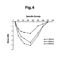
- the assembly of a pneumatic tyre, a wheel rim and a damper was mounted on a test car and run on a noise test course (rough asphalt road) at a speed of 60 km/hr, and the sound pressure was measured near the driver's seat to obtain the overall noise level of 226, 240 and 253 Hz.
- the results are indicated in dB as a difference from a reference tyre provided with no damper, wherein the minus sign means that the noise was reduced.
- Tables 1A, 1B and 1C each show a change in the noise level when only the specific gravity of the damper was changed.
- Each damper was made of open-cell type polyurethane foam and disposed in the cavity without being fixed. These data are also plotted on a graph shown in Fig.4 .
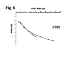
- Tables 2A and 2B show a change in the noise level when the size of the damper was changed with maintaining a specific gravity of 0.022.
- Each damper was made of open-cell type polyurethane foam and disposed in the cavity without being fixed.
- Table 2A Damper Volume S2(cm 3 ) 198 330 660 990 1320 1518 5500 7700 Thickness (mm) 10 10 10 10 10 50 70 Width (mm) 110 110 110 110 110 110 110 110 Length (mm) 180 300 600 900 1200 1380 1000 1000 S2/S1 (%) 0.52 0.87 1.74 2.62 3.49 4.01 14.53 20.34 Noise (dB) -2.3 -2.6 -3.6 -4.7 -5.6 -5.9 -8.9 -9.1 Test car: Japanese 4000cc FR passenger car Wheel rim size: 16X7JJ Tyre size: 225/60R16 98H Inner pressure: 200 KPa Cross section area of cavity: 23174 mm 2 Maximum width of cavity: 214 mm Test car: Japanese 1500cc FF passenger car Wheel rim size: 15X5JJ Tyre size: 165/65R15
- Table 3 shows the test results when the damper was fixed or secured.
- the damper was made of open-cell type polyurethane foam having a specific gravity of 0.022.
- the effectual surface area of the damper decreases when one side of the damper is bonded to the tyre or rim. Therefore, there is a possibility that the noise reduction becomes less when compared with a free damper. In case of a loosely looped damper as shown in Fig.3 , it is possible to increase the effectual surface area without increasing a load on the inside of the tyre.
- Table 4 shows the test results when a damper of open-cell type polyurethane foam which was not fully expanded in its edge portion of about 5 mm width was disposed in the cavity without being fixed.
- the specific gravity was 0.022.
Claims (7)
- Reifengeräuschverringerungssystem, umfassend
eine Radfelge (3a),
einen Luftreifen (2), der auf die Radfelge (3a) aufzuziehen ist, und
einen Geräuschdämpfer (6), der in einem kreisringförmigen Reifenhohlraum (4), der durch die Radfelge (3a) und den darauf aufgezogenen Luftreifen (2) umschlossen ist, anzuordnen ist, wobei
der Geräuschdämpfer (6) ein Streifen aus mehrzelligem Material (5) ist, der
eine Länge von nicht weniger als 250 mm,
eine Breite (BW) von nicht weniger als 20 % der maximalen Querschnittsbreite (W) des Reifenhohlraums und
ein Volumen (S2) von nicht weniger als 0,4 % des Volumens (S1) des kreisringförmigen Reifenhohlraums (4) aufweist, und
die gesamte Länge des Geräuschdämpfers (6) an dem Reifen oder der Radfelge unter Verwendung eines Klebstoffes befestigt ist,
dadurch gekennzeichnet, dass
die Länge des an dem Reifen (2) befestigten Geräuschdämpfers (6) kürzer ist als der Umfang des Reifens (2) oder
die Länge des an der Felge (3a) befestigten Geräuschdämpfers (6) kürzer ist als der Umfang der Felge (3a). - Reifengeräuschverringerungssystem nach Anspruch 1,
dadurch gekennzeichnet, dass
die gesamte Länge des Geräuschdämpfers (6) an der Innenfläche eines Laufflächenabschnitts des Reifens befestigt ist. - Reifengeräuschverringerungssystem nach Anspruch 1 oder 2,
dadurch gekennzeichnet, dass
das Volumen (S2) nicht größer als 20 % des Volumens (S1) ist. - Reifengeräuschverringerungssystem nach Anspruch 1, 2 oder 3,
dadurch gekennzeichnet, dass
die relative Dichte des Geräuschdämpfers (6) in einem Bereich von 0,005 bis 0,06 liegt. - Reifengeräuschverringerungssystem nach Anspruch 1, 2 oder 3,
dadurch gekennzeichnet, dass
die relative Dichte des Geräuschdämpfers (6) in einem Bereich von 0,016 bis 0,05 liegt. - Reifengeräuschverringerungssystem nach Anspruch 1,
dadurch gekennzeichnet, dass
die gesamte Länge des Geräuschdämpfers (6) an einem Felgenbett der Radfelge (3a) befestigt ist. - Luftreifen (2), der auf die Radfelge (3a) aufzuziehen ist, umfassend
einen Laufflächenabschnitt und
einen Geräuschdämpfer (6), der in einem kreisringförmigen Reifenhohlraum (4), der bei aufgezogenem Reifen durch die Radfelge (3a) und den Luftreifen (2) umschlossen ist, anzuordnen ist, wobei
der Geräuschdämpfer (6) ein Streifen aus mehrzelligem Material (5) ist, der
eine Länge von nicht weniger als 250 mm,
eine Breite (BW) von nicht weniger als 20 % der maximalen Querschnittsbreite (W) des Reifenhohlraums und
ein Volumen (S2) von nicht weniger als 0,4 % des Volumens (S1) des kreisringförmigen Reifenhohlraums (4) aufweist, und
die gesamte Länge des Geräuschdämpfers (6) an der Innenfläche des Laufflächenabschnitts unter Verwendung eines Klebstoffes befestigt ist,
dadurch gekennzeichnet, dass
die Länge des Geräuschsdämpfers (6) kürzer ist als der Umfang des Reifens (2).
Applications Claiming Priority (6)
| Application Number | Priority Date | Filing Date | Title |
|---|---|---|---|
| JP2000263518 | 2000-08-31 | ||
| JP2000263519A JP3953264B2 (ja) | 2000-08-31 | 2000-08-31 | 空気入りタイヤとリムとの組立体 |
| JP2000263518 | 2000-08-31 | ||
| JP2000263519 | 2000-08-31 | ||
| JP2000314100 | 2000-10-13 | ||
| JP2000314100A JP3990533B2 (ja) | 2000-08-31 | 2000-10-13 | 空気入りタイヤとリムとの組立体 |
Publications (3)
| Publication Number | Publication Date |
|---|---|
| EP1184207A2 EP1184207A2 (de) | 2002-03-06 |
| EP1184207A3 EP1184207A3 (de) | 2003-08-06 |
| EP1184207B1 true EP1184207B1 (de) | 2008-06-18 |
Family
ID=27344491
Family Applications (1)
| Application Number | Title | Priority Date | Filing Date |
|---|---|---|---|
| EP01307320A Expired - Lifetime EP1184207B1 (de) | 2000-08-31 | 2001-08-29 | Reifengeräuschreduzierungsvorrichtung |
Country Status (3)
| Country | Link |
|---|---|
| US (1) | US6729373B2 (de) |
| EP (1) | EP1184207B1 (de) |
| DE (1) | DE60134447D1 (de) |
Cited By (1)
| Publication number | Priority date | Publication date | Assignee | Title |
|---|---|---|---|---|
| WO2014174454A3 (en) * | 2013-04-23 | 2015-02-19 | Padmini Vna Mechatronics Pvt. Ltd | Noise dampening module for a vacuum modulator in a motor vehicle |
Families Citing this family (25)
| Publication number | Priority date | Publication date | Assignee | Title |
|---|---|---|---|---|
| JP3400787B2 (ja) * | 2000-12-26 | 2003-04-28 | 住友ゴム工業株式会社 | タイヤのアンバランス修正方法 |
| US6777037B2 (en) * | 2001-02-21 | 2004-08-17 | Hitachi, Ltd. | Plasma processing method and apparatus |
| JP4044526B2 (ja) | 2004-01-27 | 2008-02-06 | 住友ゴム工業株式会社 | 空気入りタイヤとリムとの組立体 |
| DE602004009533T2 (de) | 2004-03-16 | 2008-07-24 | Sumitomo Rubber Industries Ltd., Kobe | Reifen mit Schalldämpfer |
| JP4224432B2 (ja) * | 2004-06-14 | 2009-02-12 | 住友ゴム工業株式会社 | 空気入りタイヤとリムとの組立体 |
| ATE371546T1 (de) * | 2005-10-07 | 2007-09-15 | Pietro Garavaglia | Selbsttragender reifen für fahrradräder, motorradräder und ähnliche |
| CN101547798B (zh) * | 2006-11-21 | 2012-11-21 | 株式会社普利司通 | 轮胎-轮辋组件和用于该轮胎-轮辋组件中的海绵构件 |
| US7841370B2 (en) * | 2007-07-25 | 2010-11-30 | The Goodyear Tire & Rubber Company | Foaming liquid material and use thereof for reducing noise in mounted tires |
| US20100071820A1 (en) * | 2008-09-24 | 2010-03-25 | Bridgestone Americas Tire Operations, Llc | Tire and noise reducer |
| LT5780B (lt) | 2010-01-28 | 2011-10-25 | Aleksandras Selezniovas | Amortizuojantis ratlankis, skirtas automobilių arba kitų transporto priemonių ratų gamybai |
| US8608126B2 (en) * | 2011-03-07 | 2013-12-17 | Philip Ng | Vibration isolation brackets for roller blinds |
| DE102012021574A1 (de) * | 2012-11-02 | 2014-05-08 | Volkswagen Aktiengesellschaft | Formkörper zur Reduzierung der im Betrieb eines Reifens auftretenden Schallemissionen |
| CN106687306A (zh) | 2014-09-12 | 2017-05-17 | 株式会社普利司通 | 充气轮胎 |
| US9545820B2 (en) * | 2014-10-31 | 2017-01-17 | GM Global Technology Operations LLC | Wheel with aluminum foam for tire cavity noise suppression |
| WO2017223173A1 (en) * | 2016-06-21 | 2017-12-28 | Bridgestone Americas Tire Operations, Llc | Methods for treating inner liner surface, inner liners resulting therefrom and tires containing such inner liners |
| US11697260B2 (en) | 2016-06-30 | 2023-07-11 | Bridgestone Americas Tire Operations, Llc | Methods for treating inner liners, inner liners resulting therefrom and tires containing such inner liners |
| WO2018112125A1 (en) | 2016-12-15 | 2018-06-21 | Bridgestone Americas Tire Operations, Llc | Sealant-containing tire and related processes |
| CN106739784A (zh) * | 2017-01-03 | 2017-05-31 | 上海共佰克智能科技有限公司 | 一种车轮 |
| KR101861476B1 (ko) * | 2017-03-23 | 2018-07-05 | 한국타이어 주식회사 | 공명음 저감 공기압 타이어 |
| EP3793846A4 (de) | 2018-05-15 | 2022-01-19 | Bridgestone Americas Tire Operations, LLC | Reifen mit mehrschichtigem einsatz |
| EP3766709B1 (de) | 2019-07-18 | 2023-09-06 | Pirelli Tyre S.p.A. | Felge für fahrzeugräder mit rauschminderungssystem |
| WO2023021300A1 (en) | 2021-08-19 | 2023-02-23 | Carbon Air Limited | A vehicle wheel |
| DE102021213748A1 (de) | 2021-12-03 | 2023-06-07 | Continental Reifen Deutschland Gmbh | Fahrzeugluftreifen für geräuscharmes Fahren |
| FR3125249A1 (fr) | 2022-01-17 | 2023-01-20 | Compagnie Generale Des Etablissements Michelin | Procede de fabrication d’un assemblage a uniformite amelioree |
| FR3125253A1 (fr) | 2022-01-17 | 2023-01-20 | Compagnie Generale Des Etablissements Michelin | Assemblage a uniformite amelioree |
Family Cites Families (8)
| Publication number | Priority date | Publication date | Assignee | Title |
|---|---|---|---|---|
| DE3042350A1 (de) * | 1980-11-10 | 1982-05-27 | Teroson Gmbh, 6900 Heidelberg | Fahrzeugluftreifen |
| JPS6250203A (ja) * | 1985-08-29 | 1987-03-04 | Bridgestone Corp | 低騒音タイヤ車輪 |
| JPH0714682B2 (ja) * | 1986-11-28 | 1995-02-22 | 住友ゴム工業株式会社 | タイヤおよびリムの組立体 |
| JP3244542B2 (ja) * | 1992-09-29 | 2002-01-07 | マツダ株式会社 | 低ロードノイズホイールの製造方法 |
| JPH0752616A (ja) * | 1993-08-19 | 1995-02-28 | Bridgestone Corp | タイヤ車輪 |
| DE19746649A1 (de) * | 1997-10-22 | 1999-04-29 | Continental Ag | Kraftfahrzeug mit einem auf einer Felge aufgebrachten Reifen und Verfahren zum Herstellen eines schallabsorbierenden Einbaus |
| DE19806935C2 (de) * | 1998-02-19 | 2001-10-18 | Continental Ag | Verfahren zum Herstellen eines Fahrzeugluftreifens mit einer an seiner Innenseele anhaftenden schallabsorbierenden Schaumstoffschicht sowie gemäß diesem Verfahren hergestellter Fahrzeugluftreifen |
| JP2001239804A (ja) * | 1999-12-24 | 2001-09-04 | Sumitomo Rubber Ind Ltd | 空気入りタイヤとリムとの組立体 |
-
2001
- 2001-08-29 DE DE60134447T patent/DE60134447D1/de not_active Expired - Lifetime
- 2001-08-29 EP EP01307320A patent/EP1184207B1/de not_active Expired - Lifetime
- 2001-08-30 US US09/941,565 patent/US6729373B2/en not_active Expired - Lifetime
Cited By (1)
| Publication number | Priority date | Publication date | Assignee | Title |
|---|---|---|---|---|
| WO2014174454A3 (en) * | 2013-04-23 | 2015-02-19 | Padmini Vna Mechatronics Pvt. Ltd | Noise dampening module for a vacuum modulator in a motor vehicle |
Also Published As
| Publication number | Publication date |
|---|---|
| DE60134447D1 (de) | 2008-07-31 |
| US6729373B2 (en) | 2004-05-04 |
| EP1184207A3 (de) | 2003-08-06 |
| US20020059971A1 (en) | 2002-05-23 |
| EP1184207A2 (de) | 2002-03-06 |
Similar Documents
| Publication | Publication Date | Title |
|---|---|---|
| EP1184207B1 (de) | Reifengeräuschreduzierungsvorrichtung | |
| EP1253025B1 (de) | Reifengeräusch reduzierende Vorrichtung | |
| EP1607243B1 (de) | Geräuschreduzierendes System für Fahrzeugreifen | |
| EP1574360B1 (de) | Schalldämpfer | |
| EP1559590B1 (de) | Reifenlärmminderungssystem | |
| EP1876038B2 (de) | Aus einem luftreifen und einer felge bestehende anordnung | |
| EP2017092B1 (de) | Luftreifensatz | |
| EP2067633B1 (de) | Reifenlärmverringerungsvorrichtung und luftreifen | |
| JP3953264B2 (ja) | 空気入りタイヤとリムとの組立体 | |
| US7360570B2 (en) | Low noise tire support ring | |
| EP1992501B1 (de) | Reifenlärmverringerungsvorrichtung und luftreifen | |
| JP3974437B2 (ja) | 空気入りタイヤ | |
| US20020124921A1 (en) | Method of correcting tire unbalance | |
| EP1125771B1 (de) | Reifengeräuschreduzierungsvorrichtung | |
| JP2975438B2 (ja) | 空気入りタイヤ | |
| EP1214205B1 (de) | Verfahren und dämpfungsvorrichtung zur reduzierung des fahrzeugrollgeräusches,und reifen mit derselben vorrichtung | |
| US20020144760A1 (en) | Method and deadening device for reducing the noise in a vehicle during travel, and tyre wheel provided with the said device | |
| JPH07115563B2 (ja) | 低騒音化した空気入りタイヤ及びその製法 | |
| JP3990533B2 (ja) | 空気入りタイヤとリムとの組立体 | |
| JP2002120511A (ja) | 空気入りタイヤ | |
| JP2002103926A (ja) | 安全空気入りタイヤ | |
| JP2002067631A (ja) | 安全空気入りタイヤ |
Legal Events
| Date | Code | Title | Description |
|---|---|---|---|
| PUAI | Public reference made under article 153(3) epc to a published international application that has entered the european phase |
Free format text: ORIGINAL CODE: 0009012 |
|
| AK | Designated contracting states |
Kind code of ref document: A2 Designated state(s): AT BE CH CY DE DK ES FI FR GB GR IE IT LI LU MC NL PT SE TR |
|
| AX | Request for extension of the european patent |
Free format text: AL;LT;LV;MK;RO;SI |
|
| PUAL | Search report despatched |
Free format text: ORIGINAL CODE: 0009013 |
|
| AK | Designated contracting states |
Designated state(s): AT BE CH CY DE DK ES FI FR GB GR IE IT LI LU MC NL PT SE TR |
|
| AX | Request for extension of the european patent |
Extension state: AL LT LV MK RO SI |
|
| 17P | Request for examination filed |
Effective date: 20040120 |
|
| AKX | Designation fees paid |
Designated state(s): DE FR GB |
|
| 17Q | First examination report despatched |
Effective date: 20050629 |
|
| GRAP | Despatch of communication of intention to grant a patent |
Free format text: ORIGINAL CODE: EPIDOSNIGR1 |
|
| GRAS | Grant fee paid |
Free format text: ORIGINAL CODE: EPIDOSNIGR3 |
|
| GRAA | (expected) grant |
Free format text: ORIGINAL CODE: 0009210 |
|
| AK | Designated contracting states |
Kind code of ref document: B1 Designated state(s): DE FR GB |
|
| REG | Reference to a national code |
Ref country code: GB Ref legal event code: FG4D |
|
| REF | Corresponds to: |
Ref document number: 60134447 Country of ref document: DE Date of ref document: 20080731 Kind code of ref document: P |
|
| PLBE | No opposition filed within time limit |
Free format text: ORIGINAL CODE: 0009261 |
|
| STAA | Information on the status of an ep patent application or granted ep patent |
Free format text: STATUS: NO OPPOSITION FILED WITHIN TIME LIMIT |
|
| 26N | No opposition filed |
Effective date: 20090319 |
|
| PGFP | Annual fee paid to national office [announced via postgrant information from national office to epo] |
Ref country code: GB Payment date: 20090826 Year of fee payment: 9 |
|
| GBPC | Gb: european patent ceased through non-payment of renewal fee |
Effective date: 20100829 |
|
| PG25 | Lapsed in a contracting state [announced via postgrant information from national office to epo] |
Ref country code: GB Free format text: LAPSE BECAUSE OF NON-PAYMENT OF DUE FEES Effective date: 20100829 |
|
| REG | Reference to a national code |
Ref country code: FR Ref legal event code: PLFP Year of fee payment: 16 |
|
| REG | Reference to a national code |
Ref country code: FR Ref legal event code: PLFP Year of fee payment: 17 |
|
| REG | Reference to a national code |
Ref country code: FR Ref legal event code: PLFP Year of fee payment: 18 |
|
| PGFP | Annual fee paid to national office [announced via postgrant information from national office to epo] |
Ref country code: FR Payment date: 20200715 Year of fee payment: 20 Ref country code: DE Payment date: 20200819 Year of fee payment: 20 |
|
| REG | Reference to a national code |
Ref country code: DE Ref legal event code: R071 Ref document number: 60134447 Country of ref document: DE |