EP1184104A1 - Feeder insert - Google Patents
Feeder insert Download PDFInfo
- Publication number
- EP1184104A1 EP1184104A1 EP01117412A EP01117412A EP1184104A1 EP 1184104 A1 EP1184104 A1 EP 1184104A1 EP 01117412 A EP01117412 A EP 01117412A EP 01117412 A EP01117412 A EP 01117412A EP 1184104 A1 EP1184104 A1 EP 1184104A1
- Authority
- EP
- European Patent Office
- Prior art keywords
- feeder
- feeder insert
- molding
- elements
- shaped element
- Prior art date
- Legal status (The legal status is an assumption and is not a legal conclusion. Google has not performed a legal analysis and makes no representation as to the accuracy of the status listed.)
- Granted
Links
Images

Classifications
-
- B—PERFORMING OPERATIONS; TRANSPORTING
- B22—CASTING; POWDER METALLURGY
- B22C—FOUNDRY MOULDING
- B22C9/00—Moulds or cores; Moulding processes
- B22C9/08—Features with respect to supply of molten metal, e.g. ingates, circular gates, skim gates
- B22C9/088—Feeder heads
Definitions
- the present invention relates primarily to a closed one Feeder insert, also called feeder for short, for use with Pouring metals into molds, with a cavity for receiving liquid Metal.
- Such feeder inserts are used in the manufacture of a mold integrated into this and form a space surrounded by molding material, the has a passage (passage) to the mold cavity and during casting is filled by the pouring stream with liquid metal that during the Flow solidification process back to the casting and the volume deficit to compensate for the solidification of the casting. In this way the Formation of so-called blowholes (these are shrinkage cavities caused by the Metal volume contraction during the solidification process) prevented.
- the metal in the feeder solidifies later than the metal of the casting, i.e. the module (ratio of volume to surface) of the feeder must be larger than that of the casting.
- the modules (ratio of volume to surface) of the feeder must be larger than that of the casting.
- the walls of the feeder become frequent made of an exothermic material, for example an aluminothermic Mixture, formed.
- an exothermic material for example an aluminothermic Mixture
- the molding material usually molding sand, in individual cases also other granular materials
- Feeder inserts are often designed to be very small.
- the feeder insert tapers thus considerably towards its top surface, and at Applying the molding material to the molding plate often gives rise to the subsequent problem on that the compression of the molding material in the vicinity of the esophagus insufficiently close to the top surface, which is disadvantageous when casting is.
- Spring mandrels as well as fixed (rigid) mandrels are designed to to hold a feeder insert in a predetermined position.
- she typically include (a) a tubular member for attachment a model plate, (b) one arranged in the tubular element Spring and (c) a resting on the spring, in the longitudinal direction within the tubular element telescopically displaceable mandrel tip element.
- Such a spring mandrel is usually on the model plate (model surface) attached, and then a feeder insert is placed on it, the lower surface of which is in the starting arrangement before the filling of the Molding material is located at a predetermined distance from the model surface.
- the subsequent filling of the molding material therefore also runs between model surface and feeder (bottom surface).
- the feeder insert placed on the spring mandrel acts a force in the direction of the model plate that causes the feeder insert against the action of the spring force in the direction of the Model plate is pressed. The in the gap between feeder insert and The molded material layer on the model plate is compressed.
- the footprint of the feeder insert to be specified should be included preferably be dimensioned small without relevant stability disadvantages can.
- the feeder insert to be specified should also be together can be used with a crushing core that separates the residual feeder relieved by the casting.
- a crushing core is in the Framework of the present text as part of the use of food understood and not as a separate component.
- the task is solved by specifying a closed one Feeder insert of the type mentioned, wherein the feeder insert at least two into one another along a longitudinal axis of the feeder (telescopic) comprises displaceable shaped elements which liquid the cavity for receiving Enclose metal on the side.
- a first shaped element is closer to Passage of the feeder insert arranged as an associated second Feature.
- the displaceability of the first and second shaped elements into one another causes that during a normal compression process in the longitudinal direction of the feeder high acting on the feeder insert according to the invention Compression pressures (compression forces) do not lead to its destruction, but only to a tolerated, by the compressibility of the surrounding molding material (molding sand) limited insertion of a molding element into the other.
- Compression pressures compression forces
- the footprint of the feeder insert can small and the wall of the feeder is comparatively thin.
- the shaped elements should be out of their initial arrangement, i.e. out the relative arrangement out for the molded elements before wrapping the Feeder insert with molding material is provided, at least by 5 mm, can preferably be pushed into each other by 10 mm.
- the feeder insert can meet the requirements of the individual case correspondingly, for example, in the manner of a compact or ball feeder designed or with an almost cylindrical feeder cap in the upper area be provided.
- spring mandrels with the feeder inserts according to the invention is therefore not excluded, but usually can on it to be dispensed with.
- a preferred feeder insert according to the invention is therefore set up for use with a centering mandrel, in particular can be designed as a self-centering feeder.
- a self-centering Suer has one or more wall sections that towards the upper one in operation (opposite the feeder passage) Taper the end wall of the feeder so that a thorn tip when positioning the feeder insert in these along these sections Target position is performed.
- Is a self-centering feeder according to the invention especially suitable for use on fast molding lines.
- First and second shaped element of a feeder insert according to the invention can be glued together or otherwise after their manufacture get connected.
- the shaped elements can also be used as separate parts stored and combined (stacked) as needed.
- Identical first (or second) form elements can also be constructed (e.g. in size) different second (or first) form elements can be combined into respective feeder inserts according to the invention.
- the holding elements are preferably an integral part of the respective formula element, and they can be used in the manufacture of each Form elements can be molded onto this without an additional step. It can with them in particular around standing or clamping projections, rotating Stand rings, pins that can be brought into engagement with complementary recesses or act like that. It is important that the holding elements are designed to operate in the foundry when the first and second
- the molding element is still roughly in its initial arrangement, the molding material but is already filled in the mold box by the subsequent one Molding material compression process from its associated shaped element can be separated or at least deformed to the extent that the first and can slide one another into each other.
- the holding elements are therefore preferably only via small connecting surfaces with their associated one Form element connected.
- a Spring mandrel As an alternative to using holding elements, the use of a Spring mandrel.
- One such can namely be a second one, the upper one in operation Form element in the intended starting position relative to the model surface and hold to the first shaped element without the inventive Feeder insert itself includes holding elements. Since spring mandrels, however, like mentioned at the outset are quite expensive and prone to wear, their use be limited to exceptional cases.
- This is preferably closer to the passage of the feeder insert this forming the first shaped element so that it (if necessary after separating or deforming holding elements) into the second shaped element can be inserted.
- the outer dimensions of the first, in Operation of lower form elements closer to the casting are therefore preferred smaller than the internal dimensions of the associated second, upper in operation Form element.
- This configuration is the reverse of that (Also according to the invention) embodiment in which the upper in operation Shaped element can be inserted into the lower shaped element, advantageous because it ensures that no disturbing quantities are present during the filling process Penetrate molding material into the first molding element.
- An embodiment is particularly advantageous in which the first, in Operation lower mold element is designed so that it (telescopic) in the second shaped element can be inserted, the outer wall of the first form elements in the inner wall of the second form element intervenes.
- the gap width between the outer wall of the first Form elements and the inner wall of the second form element is in the intended starting arrangement of the shaped elements, which if necessary is characterized by the position of the holding elements, preferably maximum 3 mm, advantageously not more than 1.5 mm.
- the shaped elements should come from their intended, if necessary output arrangement defined by the holding elements in the longitudinal direction of the feeder by at least 5 mm, preferably by at least 10 mm leave before pushing due to further nesting Forces occurring between the shaped elements to tear or Breaking of the first or second feature comes.
- the first and / or the second shaped element comprises one or more guide elements which are set up tilting or tilting of the two shaped elements relative to one another to prevent at least essentially when this (from the output arrangement out) shifted into each other along the longitudinal axis of the feeder become.
- These guide elements preferably have the shape themselves Thin strips or ridges extending along the length of the feeder, and them are advantageously located on the outer wall of that molded element, which can be inserted into the partner form element; in So in a lot of cases they are on the outside of the first Formula elements arranged.
- the first molded element is an inventive one Feeder insert integrated a breaking edge, which if necessary Is part of a crushing core, which is then directly on the model plate during operation can be put on.
- This integration of a breaking edge ensures a significant reduction in Cleaning effort in comparison with the known feeder inserts used for Use with spring mandrels are provided and therefore no breaking edge (no crusher core).
- the footprint of the feeder according to the invention can be very difficult, especially when using a crushing edge (a crushing core) be kept small.
- the feeder insert according to the invention or the associated shaped elements can partially or completely from insulating or exothermic molding compounds be made. If a crushing core is integrated in the first shaped element, so this is typically not exothermic, the associated second The shaped element will then often be exothermic.
- the feeder inserts according to the invention comprise two or more Form elements that can be combined as required when stored separately can.
- the invention therefore also relates to a kit for manufacturing of a feeder insert according to the invention, comprising a first shaped element and a second shaped element which can be arranged so that they can be moved into one another along a longitudinal axis of the feeder.
- preferred Embodiments of the form elements belonging to the kit are the above statements to remove the feeder insert according to the invention.
- the molding machine usually includes a model plate (i.e. a model device for molding machines, usually consisting of a flat plate with cast-in or mechanically fastened models), and the first mold element is preferably arranged so that it is in front the compression process in direct contact with the model plate (the Model surface). This is especially true if in the first Forming element is integrated into a crushing core.
- a model plate i.e. a model device for molding machines, usually consisting of a flat plate with cast-in or mechanically fastened models
- the first mold element is preferably arranged so that it is in front the compression process in direct contact with the model plate (the Model surface). This is especially true if in the first Forming element is integrated into a crushing core.
- Feeder insert 2 comprises a first (lower) molded element 4 and a second (Upper) shaped element 6, both shaped elements being essentially rotationally symmetrical are trained.
- the longitudinal axis of rotation the Spelser insert 2 is shown by a dashed line Line 20 marked.
- the first shaped element 4 is again separately in FIG. 1b Longitudinal section and shown in Fig. 1b in plan view. It's over a molding compound (e.g. insulating or exothermic) shaped and relative thin-walled.
- the footprint of the first form element 4, with the this sits on a model plate 22 is small, the footprint diameter is only about 40 mm, the diameter of the inside of the footprint lying feeder passage only about 20 mm.
- the first shaped element widens to the maximum outside Diameter of about 77 mm conical, and the conical so defined Section 34 then merges into an upper section 44, which follows very slightly conical up to a diameter of about 76 mm rejuvenated.
- Retaining projections 12 are formed.
- the (imaginary) connection surfaces between Retaining projections 12 and shaped element 4 are each quite small, so that the Holding projections 12 mechanically from the molded element with little effort can be separated.
- a total of four are also assigned to the holding projections 12 Guide and spacer strips 14, which start from the holding projections extend in the longitudinal direction of the feeder insert 2 and opposite the outer wall of the upper section 44 of the lower molding 4 each project by about 2 mm.
- the second (upper) molding element 6 is the second (upper) molding element 6. It is molded from an exothermic molding compound and is also quite thin-walled educated. The outer contour of the upper molded element 6 tapers upwards slightly towards one on the outside essentially flat upper wall termination 36.
- the inner wall of the upper Formula elements 4 initially proceed from its lower edge 26 parallel to the outer wall of the upper section 44 of the lower molding 4 and then goes into a conically tapering wall section 46 above, along which the tip of a centering mandrel at Positioning the feeder insert can be performed.
- the conical Wall section 46 finally opens into one in the feed axis lying, through the end 36 centering recess 56 for Picking up a mandrel tip.
- the two shaped elements 4, 6 are designed so that the four Guide strips 14 of the lower molding 4 frictionally on the inner wall of the upper molding element 6, if this, as in Fig. 1a shown in the starting arrangement on the four retaining projections of the lower form elements 4 rests. They therefore cause an interference fit and prevent an undesirable lateral displacement of the two shaped elements; they also define a uniform width of the gap between the lower (here inner) and upper (here outer) form element.
- a centering mandrel 16 is also shown in FIG. which is attached to the model plate 22 and from there (always in the feeder axis of rotation 20 lying) through the feeder passage 10 and through the feeder cavity into the centering recess 56 extends.
- the two shaped elements 4, 6 of the feeder insert 2 can be Slide telescopically into each other if parallel to the axis of rotation 20 a force directed onto the model plate 22 (arrow F) on the feeder insert acts, as for example after the filling of molding material Compression molding is the case (see Fig. 3a-d).
- the force just needs to do this be sufficiently large to hold the retaining projections 12 from the lower mold element 4 separate.
- the inner wall of the second (upper, outer) molded element approaches itself when pushed onto the first (lower, inner) form element Outer wall continuously and finally arrives after a displacement path of approx. 15 mm, all around in contact with it. Such a shift path sufficient for many compaction processes.
- the end position of the lower edge 26 of the upper molded element 6 after covering the above Displacement path is indicated by a dashed line.
- the Guide strips 14 are 4.6 when pushing the form elements deformed or separated and / or cut into the inner wall of the outer (upper) form elements 6.
- the centering recess 56 extends through the upper end wall of the feeder insert 2 and the tip of the centering mandrel includes a cylindrical section that is significantly longer than 15 mm and the diameter of which corresponds to the inner diameter of the centering recess 56 is adjusted. That is why it happens when telescoping the upper one on the lower form element does not cause disability; the thorn tip kicks rather, emerge unhindered from the feeder insert.
- the lower edge 26 of the wall projecting beyond the lower shaped element 4 of the upper molding element 6 acts like one during a compression process Stamp surface on the molding material to be compressed between edge 26 and Model plate 22.
- the (also) using a compression process The operations of the feeder insert 2 are described below with reference to FIG. 3a-d explained in more detail.
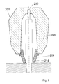
- FIG. 2 shows an alternative feeder insert 202 according to the invention shown in longitudinal section.
- the feeder insert 202 is more compact and thicker walled than the feeder insert 2.
- the existing one here Centering recess 256 does not pass through the upper feeder end, but extends so far in the longitudinal direction of the feeder insert that an assigned centering pin is inserted far enough into it can be, if the upper mold element 206 telescopically on the lower Form element 204 is moved in the direction of the model plate.
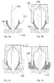
- 3a-d is an inventive method for arrangement of a feeder insert according to the invention in a casting mold schematically shown.
- the following explanations apply to the use of feeders 1a-c as well as for the feeder insert from FIG. 2.
- a first shaped element 104 is placed on a centering mandrel 116 placed, which is attached to a model plate 122.
- the form element 104 is in direct contact with the model plate 122 brought.
- a second shaped element 106 is then placed on the first shaped element 104 placed so that it is supported by this.
- To holding projections 112 are provided, for example, in their shape and function of the holding projections 12 explained with reference to FIGS. 1a-c correspond.
- a composite feeder insert 102 in its starting arrangement, cf. Fig. 1a.
- the feeder insert is used 102 coated with molding sand 150 or another molding material (wrapping only indicated in the lower area).
- the holding projections 112 are from the first Molded element 104 broken off, the second (upper) shaped element 106 telescopically a little bit onto the first (lower) shaped element 104 postponed.
- the displacement path D of the second molding element 106 on the the first shaped element 104 fixed in position is determined by the dimension predetermined and limited the compression of molding material.
Landscapes
- Engineering & Computer Science (AREA)
- Mechanical Engineering (AREA)
- Molds, Cores, And Manufacturing Methods Thereof (AREA)
- Moulds For Moulding Plastics Or The Like (AREA)
- Eye Examination Apparatus (AREA)
- Valve-Gear Or Valve Arrangements (AREA)
- Mechanical Treatment Of Semiconductor (AREA)
- Injection Moulding Of Plastics Or The Like (AREA)
Abstract
Description
Die vorliegende Erfindung betrifft primär einen geschlossenen Speisereinsatz, nachfolgend auch kurz Speiser genannt, zur Verwendung beim Gießen von Metallen in Gießformen, mit einem Hohlraum zur Aufnahme flüssigen Metalls.The present invention relates primarily to a closed one Feeder insert, also called feeder for short, for use with Pouring metals into molds, with a cavity for receiving liquid Metal.
Derartige Speisereinsätze werden bei der Herstellung einer Gießform in diese integriert und bilden einen von Formstoff umgebenen Raum, der einen Durchlaß (Durchtritt) zum Formhohlraum hin aufweist und beim Gießen von der Gießströmung mit flüssigem Metall gefüllt wird, das während des Erstarrungvorganges zum Gußstück zurückströmen und das Volumendefizit bei der Erstarrung des Gußstücks kompensieren soll. Auf diese Weise wird die Bildung sogenannter Lunker (das sind Schwindungshohlräume, die durch die Metallvolumen-Kontraktion beim Erstarrungsvorgang entstehen) verhindert.Such feeder inserts are used in the manufacture of a mold integrated into this and form a space surrounded by molding material, the has a passage (passage) to the mold cavity and during casting is filled by the pouring stream with liquid metal that during the Flow solidification process back to the casting and the volume deficit to compensate for the solidification of the casting. In this way the Formation of so-called blowholes (these are shrinkage cavities caused by the Metal volume contraction during the solidification process) prevented.
Um einen ordnungsgemäßen Speisungsvorgang zu gewährleisten, muß das im Speiser befindliche Metall später erstarren als das Metall des Gußstücks, d.h. der Modul (Verhältnis von Volumen zu Oberfläche) des Speisers muß größer als das des Gußstücks sein. Zugleich soll nach der Erstarrung aus Kostengründen eine möglichst geringe Restmenge an Metall im Speiser verbleiben, und zu diesem Zweck werden die Wandungen des Speisers häufig aus einem exothermen Material, beispielsweise einer aluminothermischen Mischung, gebildet. Ein solches Material wird durch das flüssige Metall gezündet, und es läuft deshalb nach dem Eindringen der Gießströmung in einen solchen Speiser eine exotherme Reaktion ab, durch die dem im Speiserinnenraum befindlichen Metall Wärme zugeführt wird. Dieses bleibt durch die Wärmezufuhr länger flüssig als das Metall im Formhohlraum der Gießform und ist dadurch besser für die Speisung nutzbar.In order to ensure a proper feeding process, the metal in the feeder solidifies later than the metal of the casting, i.e. the module (ratio of volume to surface) of the feeder must be larger than that of the casting. At the same time, after solidification For cost reasons, the smallest possible amount of metal in the feeder remain, and for this purpose the walls of the feeder become frequent made of an exothermic material, for example an aluminothermic Mixture, formed. Such a material is made by the liquid metal ignited, and therefore it runs in after the pouring flow such a feeder exotherms, resulting in the inside of the feeder existing metal heat is supplied. This remains through the Heat supply liquid longer than the metal in the mold cavity of the mold and is therefore better usable for feeding.
Viele Gießformen werden mit Hilfe einer Modellplatte hergestellt, welche die Innenkontur des Formhohlraumes vorgibt. An den Stellen, an denen ein Speisereinsatz erforderlich ist, ist dann häufig jeweils eine Halteeinrichtung für den Speisereinsatz vorgesehen, z.B. ein Dorn zur Fixierung der Lage des Speisereinsatzes.Many molds are made using a model plate, which specifies the inner contour of the mold cavity. In the places where a feeder insert is required, then is often a holding device intended for use in feeders, e.g. a thorn to fix the Location of the feeder insert.
Nach dem Aufsetzen der Speiser auf die Modellplatte (mit oder ohne Dorn) wird dann der Formstoff (in der Regel Formsand, in Einzelfällen auch andere körnige Materialien) so auf die Modellplatte aufgebracht, daß er den Speisereinsatz umhüllt. In einem weiteren Schritt wird der Formstoff dann verdichtet und der Speiser dabei mehr oder weniger fest vom verdichteten Formstoff eingeschlossen. Man spricht insoweit auch von Formpressung.After placing the feeders on the model plate (with or without Thorn) then becomes the molding material (usually molding sand, in individual cases also other granular materials) so applied to the model plate that he the Covered feeder insert. In a further step, the molding material is then condensed and the feeder more or less firmly from the condensed Molded material included. In this respect, one speaks of compression molding.
Im Bestreben, eine punktuelle Dichtspeisung auch kleiner Gußstückbereiche zu erreichen, werden die Stell- oder Aufsatzflächen moderner Speisereinsätze häufig sehr klein ausgelegt. Der Speisereinsatz verjüngt sich somit in Richtung auf seine Aufsatzfläche beträchtlich, und beim Aufbringen des Formstoffs auf die Formplatte tritt häufig das Folgeproblem auf, daß die Verdichtung des Formstoffs in der Umgebung des Speiserhalses nahe der Aufsatzfläche nur unzureichend erfolgt, was beim Abguß nachteilig ist.In the endeavor to selectively feed even small areas of castings to achieve, the space or top areas are more modern Feeder inserts are often designed to be very small. The feeder insert tapers thus considerably towards its top surface, and at Applying the molding material to the molding plate often gives rise to the subsequent problem on that the compression of the molding material in the vicinity of the esophagus insufficiently close to the top surface, which is disadvantageous when casting is.
Ein weiteres Problem besteht darin, daß insbesondere exotherme aber auch isolierende Speiser den mit dem Vorgang der Formstoff-Verdichtung verbundenen Stauchkräften häufig nicht standhalten können und daher zerbrechen. Ein solches Zerbrechen führt dann unvermeidlich zu einer unkontrollierten Speisung des Gußstücks.Another problem is that in particular exothermic insulating feeders also with the process of molding compression associated upsetting forces often cannot withstand and therefore break. Such a break will inevitably lead to one uncontrolled feeding of the casting.
Trotz dieses seit längerem bekannten Problems geht der Trend zu immer höheren Verdichtungsdrücken, was die Hersteller von Speisereinsätzen bereits dazu gezwungen hat, besonders stabile, dickwandige Speisereinsätze anzubieten, die aufgrund des erhöhten Materialbedarfs allerdings recht teuer sind. Despite this problem, which has been known for a long time, the trend is forever higher compression pressures, what the manufacturers of feeder inserts has already forced particularly stable, thick-walled feeder inserts to offer, but due to the increased material requirements quite are expensive.
Seit einigen Jahren wird versucht, den mit der Erhöhung des Verdichtungsdrucks verknüpften Problemen mittels sogenannter Federdorne zu begegnen. Federdorne sind ebenso wie feste (starre) Dorne dazu bestimmt, einen Speisereinsatz in einer vorbestimmten Position zu halten. Sie umfassen in der Regel (a) ein röhrenförmiges Element zur Befestigung auf einer Modellplatte, (b) eine in dem röhrenförmigen Element angeordnete Feder und (c) ein auf der Feder ruhendes, in Längsrichtung innerhalb des röhrenförmigen Elements teleskopartig verschiebbares Dornspitzen-Element. Ein solcher Federdorn wird üblicherweise auf der Modellplatte (Modelloberfläche) befestigt, und auf ihn wird dann ein Speisereinsatz aufgesetzt, dessen Unterfläche sich in der Ausgangsanordnung vor dem Einfüllen des Formstoffs in einem vorbestimmten Abstand zur Modelloberfläche befindet. Beim anschließenden Einfüllen des Formstoffs läuft dieser daher auch zwischen Modelloberfläche und Speiser(-unterfläche). Und somit besteht bei der anschließenden Verdichtung (Formpressung) kein direkter Kontakt zwischen Speiser und Modelloberfläche, so daß eine Zerstörung des Speisers auch bei Applikation hoher Verdichtungsdrücke in der Regel verhindert wird. Auf den auf den Federdorn aufgesetzten Speiser-Einsatz wirkt beim Formpressen eine Kraft in Richtung auf die Modellplatte, die dazu führt, daß der Speiser-Einsatz gegen die Wirkung der Federkraft in Richtung auf die Modellplatte gepresst wird. Die in dem Spalt zwischen Speiser-Einsatz und Modellplatte befindliche Formstoff-Schicht wird dabei verdichtet.For some years now, attempts have been made to increase the compression pressure linked problems using so-called spring mandrels to encounter. Spring mandrels as well as fixed (rigid) mandrels are designed to to hold a feeder insert in a predetermined position. she typically include (a) a tubular member for attachment a model plate, (b) one arranged in the tubular element Spring and (c) a resting on the spring, in the longitudinal direction within the tubular element telescopically displaceable mandrel tip element. Such a spring mandrel is usually on the model plate (model surface) attached, and then a feeder insert is placed on it, the lower surface of which is in the starting arrangement before the filling of the Molding material is located at a predetermined distance from the model surface. The subsequent filling of the molding material therefore also runs between model surface and feeder (bottom surface). And so there is at the subsequent compression (compression molding) no direct contact between feeder and model surface, so that destruction of the feeder is usually prevented even when applying high compression pressures. During compression molding, the feeder insert placed on the spring mandrel acts a force in the direction of the model plate that causes the feeder insert against the action of the spring force in the direction of the Model plate is pressed. The in the gap between feeder insert and The molded material layer on the model plate is compressed.
Der Einsatz von Federdornen hat zwar zur Linderung der vorstehend geschilderten Probleme beigetragen, bringt aber wiederum eine Reihe anderer Probleme mit sich.The use of spring mandrels does alleviate the above problems described, but again brings a number of others Problems with themselves.
So erfolgt die Trennung des sogenannten Restspeisers (d.h. des nach dem Guß im Speisereinsatz verbleibenden, erstarrten Metalls) vom Gußstück häufig nicht unmittelbar an der Sollbruchstelle, d.h. der gedanklichen Grenzfläche zwischen Gußstück und Speiser, sondern in einem beträchtlichen Abstand vom Gußstück, irgendwo im Bereich des häufig mehrere Zemtimeter breiten Sandspalts zwischen Gußstück und Speisereinsatz.This is how the so-called residual feeder (i.e. the downstream) is separated solidified metal remaining in the feeder insert) from the casting often not directly at the predetermined breaking point, i.e. the mental Interface between casting and feeder, but in a considerable Distance from the casting, somewhere in the range of often several centimeters wide sand gap between the casting and feeder insert.
Ein sinnvoller Einsatz von Brechkernen (auch als Einschnür-, Abschlag- oder Kragenkerne bezeichnet), die im Bereich der Gießereitechnik ansonsten eingesetzt werden, um eine präzise lokalisierte Trennung von Restspeiser und Gußstück zu erreichen, war bei Verwendung von Federdornen bislang nicht möglich. Der Putzaufwand ist daher im Regelfall recht hoch. Federdorne sind überdies recht teuer und verschleißanfällig.A sensible use of crushing cores (also as constricting, or collar cores) used in the field of foundry technology otherwise used to precisely localize separation from Reaching the remaining feeder and casting was done using spring mandrels so far not possible. The cleaning effort is therefore usually quite high. Spring mandrels are also quite expensive and prone to wear.
Angesichts der vorstehend geschilderten Probleme war es die primäre Aufgabe der vorliegenden Erfindung, einen Speisereinsatz anzugeben, der im Gießereibetrieb auch hohen Verdichtungsdrücken standhält.Given the problems outlined above, it was the primary one Object of the present invention to provide a feeder insert that in Foundry operation also withstands high compression pressures.
Die Stellfläche des anzugebenden Speisereinsatzes sollte dabei vorzugsweise ohne relevante Stabilitätsnachteile klein bemessen werden können.The footprint of the feeder insert to be specified should be included preferably be dimensioned small without relevant stability disadvantages can.
Außerdem sollte der Einsatz der teuren und verschleißanfälligen Federdorne zumindest im Regelfall entbehrlich sein.In addition, the use of expensive and prone to wear Spring mandrels are at least generally not necessary.
Und schließlich sollte der anzugebende Speisereinsatz auch zusammen mit einem Brechkern eingesetzt werden können, der die Trennung des Restspeisers vom Gußstück erleichtert. Ein derartiger Brechkern wird dabei im Rahmen des vorliegenden Textes als Bestandteil des Speisereinsatzes aufgefaßt und nicht als separates Bauteil.And finally, the feeder insert to be specified should also be together can be used with a crushing core that separates the residual feeder relieved by the casting. Such a crushing core is in the Framework of the present text as part of the use of food understood and not as a separate component.
Die gestellte Aufgabe wird gelöst durch Angabe eines geschlossenen Speisereinsatzes der eingangs genannten Art, wobei der Speisereinsatz zumindest zwei entlang einer Speiser-Längsachse (teleskopartig) ineinander verschiebbare Formelemente umfaßt, die den Hohlraum zur Aufnahme flüssigen Metalls seitlich umschließen. Ein erstes Formelement ist dabei näher am Durchtritt des Speisereinsatzes angeordnet als ein zugeordnetes zweites Formelement.The task is solved by specifying a closed one Feeder insert of the type mentioned, wherein the feeder insert at least two into one another along a longitudinal axis of the feeder (telescopic) comprises displaceable shaped elements which liquid the cavity for receiving Enclose metal on the side. A first shaped element is closer to Passage of the feeder insert arranged as an associated second Feature.
Die Verschiebbarkeit von erstem und zweitem Formelement ineinander bewirkt, daß die während eines üblichen Verdichtungsvorgangs in Speiser-Längsrichtung auf den erfindungsgemäßen Speisereinsatz wirkenden hohen Verdichtungsdrücke (Stauchkräfte) nicht zu dessen Zerstörung führen, sondern lediglich zu einem tolerierten, durch die Verdichtbarkeit des umgebenden Formmaterials (Formsands) begrenzten Einschub des einen Formelements in das andere. Die Stellfläche des Speisereinsatzes kann dabei klein und die Speiserwandung vergleichsweise dünn sein. The displaceability of the first and second shaped elements into one another causes that during a normal compression process in the longitudinal direction of the feeder high acting on the feeder insert according to the invention Compression pressures (compression forces) do not lead to its destruction, but only to a tolerated, by the compressibility of the surrounding molding material (molding sand) limited insertion of a molding element into the other. The footprint of the feeder insert can small and the wall of the feeder is comparatively thin.
Die Formelemente sollten aus ihrer Ausgangsanordnung heraus, d.h. aus der Relativanordnung heraus, die für die Formelemente vor dem Umhüllen des Speisereinsatzes mit Formmaterial vorgesehen ist, zumindest um 5 mm, vorzugsweise um 10 mm ineinandergeschoben werden können.The shaped elements should be out of their initial arrangement, i.e. out the relative arrangement out for the molded elements before wrapping the Feeder insert with molding material is provided, at least by 5 mm, can preferably be pushed into each other by 10 mm.
Der Speisereinsatz kann dabei den Erfordernissen des Einzelfalls entsprechend beispielsweise nach Art eines Kompakt- oder Kugelspeisers ausgelegt oder mit einer im oberen Bereich nahezu zylindrischen Speiserkappe versehen sein.The feeder insert can meet the requirements of the individual case correspondingly, for example, in the manner of a compact or ball feeder designed or with an almost cylindrical feeder cap in the upper area be provided.
Bei Verwendung eines erfindungsgemäßen Speisereinsatzes wird es nur in Ausnahmefällen vorteilhaft sein, einen Federdorn einzusetzen, denn dessen oben beschriebene Wirkung entspricht im wesentlichen der durch den erfindungsgemäßen Speisereinsatz erreichten.When using a feeder insert according to the invention, it only becomes in exceptional cases it may be advantageous to use a spring mandrel, because the effect described above corresponds essentially to that of the reached feed insert according to the invention.
Der Einsatz von Federdornen mit den erfindungsgemäßen Speisereinsätzen ist daher zwar nicht ausgeschlossen, in der Regel kann aber auf sie verzichtet werden.The use of spring mandrels with the feeder inserts according to the invention is therefore not excluded, but usually can on it to be dispensed with.
Die Verwendung eines festen Zentrierdornes ist hingegen in vielen Fällen sinnvoll. Ein bevorzugter erfindungsgemäßer Speisereinsatz ist daher zur Verwendung mit einem Zentrierdorn eingerichtet, wobei er insbesondere als selbstzentrierender Speiser ausgebildet sein kann. Ein solcher selbstzentrierender Speiser besitzt einen oder mehrere Wandungsabschnitte, die sich in Richtung der im Betrieb oberen (dem Speiserdurchtritt gegenüberliegenden) Abschluß-Wandung des Speisers so verjüngen, daß eine Dornspitze beim Positionieren des Speisereinsatzes entlang dieser Abschnitte in ihre Sollposition geführt wird. In dem (oberen) Wandungsteil, welches dem Speiserdurchtritt gegenüberliegt, ist dann häufig eine Zentrierausnehmung zur Aufnahme der Dornspitze vorgesehen, vgl. unsere DE-Gebrauchsmusterschrift 93 03 392. Ein selbstzentrierender erfindungsgemäßer Speiser ist insbesondere für den Einsatz an schnellen Formanlagen geeignet.However, the use of a fixed centering mandrel is common in many Cases make sense. A preferred feeder insert according to the invention is therefore set up for use with a centering mandrel, in particular can be designed as a self-centering feeder. Such a self-centering Speiser has one or more wall sections that towards the upper one in operation (opposite the feeder passage) Taper the end wall of the feeder so that a thorn tip when positioning the feeder insert in these along these sections Target position is performed. In the (upper) wall part, which the Opposing feeder passage is then often a centering recess intended to accommodate the mandrel tip, cf. our DE utility model 93 03 392. Is a self-centering feeder according to the invention especially suitable for use on fast molding lines.
Erstes und zweites Formelement eines erfindungsgemäßen Speisereinsatzes können nach ihrer Herstellung miteinander verklebt oder sonstwie verbunden werden. Die Formelemente können aber auch als separate Teile gelagert und je nach Bedarf kombiniert (aufeinandergestellt) werden. Baugleiche erste (oder zweite) Formelemente können dabei mit bauartlich (z.B. in ihrer Größe) unterschiedlichen zweiten (oder ersten) Formelementen zu jeweiligen erfindungsgemäßen Speisereinsätzen kombiniert werden.First and second shaped element of a feeder insert according to the invention can be glued together or otherwise after their manufacture get connected. The shaped elements can also be used as separate parts stored and combined (stacked) as needed. Identical first (or second) form elements can also be constructed (e.g. in size) different second (or first) form elements can be combined into respective feeder inserts according to the invention.
Besonders bevorzugt sind erfindungsgemäße Speisereinsätze, bei denen am ersten und/oder zweiten Formelement ein oder mehrere Halteelemente angeordnet sind,
- über die das erste Formelement (in der Ausgangsanordnung) das zweite Formelement trägt und
- die so abtrennbar oder deformierbar sind, daß ein ineinander Verschieben der zwei Formelemente (aus der Ausgangsanordnung heraus) entlang der Speiser-Längsachse möglich ist.
- via which the first shaped element (in the starting arrangement) carries the second shaped element and
- which can be separated or deformed in such a way that the two shaped elements can be moved into one another (out of the starting arrangement) along the longitudinal axis of the feeder.
Die Halteelemente sind vorzugsweise integraler Bestandteil des jeweiligen Formelelements, und sie können bei der Herstellung des jeweiligen Formelements ohne Zusatzschritt an dieses angeformt werden. Es kann sich bei ihnen insbesondere um Stand- oder Klemmvorsprünge, umlaufende Standringe, in Eingriff mit komplementären Vertiefungen bringbare Stifte oder dergleichen handeln. Wichtig ist dabei jeweils, daß die Halteelemente so ausgelegt sind, daß sie im Gießereibetrieb, wenn erstes und zweites Formelement noch in etwa in ihrer Ausgangsanordnung vorliegen, der Formstoff aber bereits in den Formkasten eingefüllt ist, durch den anschließenden Formstoff-Verdichtungsvorgang von ihrem zugehörigen Formelement abgetrennt oder zumindest soweit deformiert werden können, daß sich erstes und zweites Formelement ineinanderschieben können. Die Halteelemente sind daher vorzugsweise nur über kleine Verbindungsflächen mit ihrem zugehörigen Formelement verbunden.The holding elements are preferably an integral part of the respective formula element, and they can be used in the manufacture of each Form elements can be molded onto this without an additional step. It can with them in particular around standing or clamping projections, rotating Stand rings, pins that can be brought into engagement with complementary recesses or act like that. It is important that the holding elements are designed to operate in the foundry when the first and second The molding element is still roughly in its initial arrangement, the molding material but is already filled in the mold box by the subsequent one Molding material compression process from its associated shaped element can be separated or at least deformed to the extent that the first and can slide one another into each other. The holding elements are therefore preferably only via small connecting surfaces with their associated one Form element connected.
Alternativ zum Einsatz von Halteelementen ist die Verwendung eines Federdorns. Ein solcher kann nämlich ein zweites, im Betrieb oberes Formelement in der vorgesehenen Ausgangsposition relativ zur Modelloberfläche und zum ersten Formelement halten, ohne daß der erfindungsgemäße Speisereinsatz selbst Halteelemente umfaßt. Da Federdorne jedoch wie eingangs erwähnt recht teuer und verschleißanfällig sind, wird ihr Einsatz auf Ausnahmefälle begrenzt sein. As an alternative to using holding elements, the use of a Spring mandrel. One such can namely be a second one, the upper one in operation Form element in the intended starting position relative to the model surface and hold to the first shaped element without the inventive Feeder insert itself includes holding elements. Since spring mandrels, however, like mentioned at the outset are quite expensive and prone to wear, their use be limited to exceptional cases.
Vorzugsweise ist das dem Durchtritt des Speisereinsatzes nähere oder diesen bildende erste Formelement so ausgestaltet, daß es (gegebenenfalls nach Abtrennung oder Deformierung von Halteelementen) in das zweite Formelement eingeschoben werden kann. Die Außenabmessungen des ersten, im Betrieb unteren, dem Gußstück näheren Formelements sind also vorzugsweise kleiner als die Innenabmessungen des zugehörigen zweiten, im Betrieb oberen Formelements. Diese Ausgestaltung ist im Vergleich mit der umgekehrten (ebenfalls erfindungsgemäßen) Ausgestaltung, bei der das im Betrieb obere Formelement in das untere Formelement einschiebbar ist, vorteilhaft, weil sie sicherstellt, daß während des Einfüllvorgangs keine störenden Mengen an Formmaterial in das erste Formelement eindringen.This is preferably closer to the passage of the feeder insert this forming the first shaped element so that it (if necessary after separating or deforming holding elements) into the second shaped element can be inserted. The outer dimensions of the first, in Operation of lower form elements closer to the casting are therefore preferred smaller than the internal dimensions of the associated second, upper in operation Form element. This configuration is the reverse of that (Also according to the invention) embodiment in which the upper in operation Shaped element can be inserted into the lower shaped element, advantageous because it ensures that no disturbing quantities are present during the filling process Penetrate molding material into the first molding element.
Besonders vorteilhaft ist eine Ausgestaltung, bei der das erste, im Betrieb untere Formelement so ausgebildet ist, daß es (teleskopartig) in das zweite Formelement eingeschoben werden kann, wobei die Außenwandung des ersten Formelements formschlüssig in die Innenwandung des zweiten Formelements eingreift. Die Spaltbreite zwischen der Außenwandung des ersten Formelements und der Innenwandung des zweiten Formelements beträgt dabei in der vorgesehenen Ausgangsanordnung der Formelemente, die gegebenenenfalls durch die Position der Halteelemente gekennzeichnet ist, vorzugsweise maximal 3 mm, vorteilhafterweise nicht mehr als 1,5 mm. Bei dieser Ausgestaltung können während des Formstoff-Einfüllens keine relevanten Formstoffmengen in den Spalt zwischen den Formelementen eindringen, so daß deren Relativ-Verschiebbarkeit zumindest nicht wesentlich beeinträchtigt wird.An embodiment is particularly advantageous in which the first, in Operation lower mold element is designed so that it (telescopic) in the second shaped element can be inserted, the outer wall of the first form elements in the inner wall of the second form element intervenes. The gap width between the outer wall of the first Form elements and the inner wall of the second form element is in the intended starting arrangement of the shaped elements, which if necessary is characterized by the position of the holding elements, preferably maximum 3 mm, advantageously not more than 1.5 mm. With this configuration can not relevant quantities of molding material during the molding material filling penetrate into the gap between the shaped elements, so that at least not significantly impaired their relative displaceability becomes.
Die Formelemente sollten sich aus ihrer vorgesehenen, gegebenenfalls durch die Halteelemente definierten Ausgangsanordnung heraus in Speiser-Längsrichtung um mindestens 5 mm, vorzugsweise um mindestens 10 mm ineinanderschieben lassen, bevor es aufgrund der bei weiterem Ineinanderschieben zwischen den Formelementen auftretenden Kräfte zu einem Reißen oder Zerbrechen des ersten oder zweiten Formelements kommt.The shaped elements should come from their intended, if necessary output arrangement defined by the holding elements in the longitudinal direction of the feeder by at least 5 mm, preferably by at least 10 mm leave before pushing due to further nesting Forces occurring between the shaped elements to tear or Breaking of the first or second feature comes.
Besonders günstig ist es, wenn das erste und/oder das zweite Formelement ein oder mehrere Führungselemente umfaßt, die eingerichtet sind, ein Verkanten oder Verkippen der zwei Formelemente relativ zueinander zumindest im wesentlichen zu verhindern, wenn diese (aus der Ausgangsanordnung heraus) entlang der Speiser-Längsachse ineinander verschoben werden. Diese Führungselemente besitzen vorzugsweise die Form sich in Speiser-Längsrichtung erstreckender dünner Leisten oder Wülste, und sie befinden sich vorteilhafterweise auf der Außenwandung desjenigen Formelements, welches in das Partner-Formelement eingeschoben werden kann; in einer Vielzahl von Fällen sind sie also auf der Außenseite des ersten Formelements angeordnet.It is particularly favorable if the first and / or the second shaped element comprises one or more guide elements which are set up tilting or tilting of the two shaped elements relative to one another to prevent at least essentially when this (from the output arrangement out) shifted into each other along the longitudinal axis of the feeder become. These guide elements preferably have the shape themselves Thin strips or ridges extending along the length of the feeder, and them are advantageously located on the outer wall of that molded element, which can be inserted into the partner form element; in So in a lot of cases they are on the outside of the first Formula elements arranged.
Vorteilhafterweise ist in das erste Formelement eines erfindungsgemäßen Speisereinsatzes eine Brechkante integriert, die gegebenenfalls Teil eines Brechkerns ist, der dann im Betrieb direkt auf die Modellplatte aufgesetzt werden kann. Diese Integration einer Brechkante (eines Brechkerns) sorgt im Gießereibetrieb für eine deutliche Verringerung des Putzaufwands im Vergleich mit den bekannten Speisereinsätzen, die zur Verwendung mit Federdornen vorgesehen sind und deshalb keine Brechkante (keinen Brechkern) besitzen. Die Stellfläche des erfindungsgemäßen Speisers kann insbesondere bei Verwendung einer Brechkante (eines Brechkerns) sehr klein gehalten werden.Advantageously, the first molded element is an inventive one Feeder insert integrated a breaking edge, which if necessary Is part of a crushing core, which is then directly on the model plate during operation can be put on. This integration of a breaking edge (a breaking core) ensures a significant reduction in Cleaning effort in comparison with the known feeder inserts used for Use with spring mandrels are provided and therefore no breaking edge (no crusher core). The footprint of the feeder according to the invention can be very difficult, especially when using a crushing edge (a crushing core) be kept small.
Der erfindungsgemäße Speisereinsatz bzw. die zugehörigen Formelemente können teilweise oder vollständig aus isolierenden oder exothermen Formmassen hergestellt sein. Wird in das erste Formelement ein Brechkern integriert, so ist dieser typischerweise nicht exotherm, das zugehörige zweite Formelement wird dann aber häufig exotherm sein.The feeder insert according to the invention or the associated shaped elements can partially or completely from insulating or exothermic molding compounds be made. If a crushing core is integrated in the first shaped element, so this is typically not exothermic, the associated second The shaped element will then often be exothermic.
Die erfindungsgemäßen Speisereinsätze umfassen zwei oder mehr Formelemente, die bei separater Lagerung bedarfsabhängig kombiniert werden können. Die Erfindung betrifft daher auch einen Bausatz zum Herstellen eines erfindungsgemäßen Speisereinsatzes, umfassend ein erstes Formelement und ein zweites Formelement, die so angeordnet werden können, daß sie entlang einer Speiser-Längsachse ineinander verschiebbar sind. Bevorzugte Ausgestaltungen der zum Bausatz gehörigen Formelemente sind den obigen Ausführungen zum erfindungsgemäßen Speisereinsatz zu entnehmen.The feeder inserts according to the invention comprise two or more Form elements that can be combined as required when stored separately can. The invention therefore also relates to a kit for manufacturing of a feeder insert according to the invention, comprising a first shaped element and a second shaped element which can be arranged so that they can be moved into one another along a longitudinal axis of the feeder. preferred Embodiments of the form elements belonging to the kit are the above statements to remove the feeder insert according to the invention.
Gemäß einem weiteren Aspekt betrifft die Erfindung ein Verfahren zur Anordnung eines Speisereinsatzes in einer Gießform, mit folgenden Schritten:
- Bereitstellen eines erfindungsgemäßen Speisereinsatzes in einer seiner vorstehend beschriebenen Ausgestaltungen,
- Anordnen des Speisereinsatzes in einer Formmaschine (dem Raum über einer Modellplatte, der in der Regel von einem aufgesetzten Formkasten umgrenzt wird) so daß das erste und das zweite Formelement eine (Ausgangs-)Anordnung einnehmen, aus der heraus die zwei Formelemente entlang einer Speiser-Längsachse ineinander verschiebbar sind,
- Einfüllen von Formstoff in die Formmaschine (den auf die Modellplatte aufgesetzten Formkasten), so daß die Außenwandungen des Speisereinsatzes mit dem Formmaterial kontaktiert sind,
- Verdichten des Formstoffs (Formpressung), so daß das erste und das zweite Formelement (gegebenenfalls nach Abtrennung oder Deformierung von Halteelementen) entlang der Speiser-Längsachse ineinander verschoben werden.
- Providing a feeder insert according to the invention in one of its configurations described above,
- Arranging the feeder insert in a molding machine (the space above a model plate, which is usually delimited by an attached molding box), so that the first and the second molding element assume an (initial) arrangement from which the two molding elements are arranged along a feeder Longitudinal axis are displaceable,
- Pouring molding material into the molding machine (the molding box placed on the model plate) so that the outer walls of the feeder insert are in contact with the molding material,
- Compression of the molding material (compression molding) so that the first and the second molding element (if necessary after separating or deforming holding elements) are pushed into one another along the longitudinal axis of the feeder.
Die Formmaschine umfaßt dabei in üblicher Weise eine Modellplatte (d.h. eine Modelleinrichtung für Formmaschinen, in der Regel bestehend aus einer flachen Platte mit eingegossenen oder mechanisch befestigten Modellen), und das erste Formelement wird vorzugsweise so angeordnet, daß es vor dem Verdichtungsvorgang in unmittelbarem Kontakt mit der Modellplatte (der Modelloberfläche) steht. Dies gilt insbesondere dann, wenn in das erste Formelement ein Brechkern integriert ist.The molding machine usually includes a model plate (i.e. a model device for molding machines, usually consisting of a flat plate with cast-in or mechanically fastened models), and the first mold element is preferably arranged so that it is in front the compression process in direct contact with the model plate (the Model surface). This is especially true if in the first Forming element is integrated into a crushing core.
Hinsichtlich weiterer bevorzugter Ausgestaltungen des erfindungsgemäßen Verfahrens wird auf die obigen Erläuterungen zu bevorzugten Speisereinsätzen verwiesen.With regard to further preferred embodiments of the invention Process is preferred to the above explanations Referrer inserts referenced.
Nachfolgend werden bevorzugte Ausgestaltungen der Erfindung anhand der beigefügten Figuren näher erläutert. Es stellen dar:
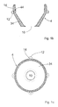
- Fig. 1a
- Längsschnitt durch einen erfindungsgemäßen Speisereinsatz in seiner Ausgangsanordnung, mit zwei ineinander verschiebbaren Formelementen, wobei der Speisereinsatz mittels eines Zentrierdorns auf einer Modellplatte befestigt ist,
- Fig. 1b
- Länsgsschnitt durch das untere (erste) Formelement des Speisereinsatzes gemäß Fig. 1a,
- Fig. 1c
- Draufsicht auf das untere (erste) Formelement des Speisereinsatzes gemäß Fig. 1a,
- Fig. 2
- Längsschnitt durch einen alternativen Speisereinsatz mit eingeformter Brechkante
- Fig. 3a - d
- Schematische Darstellung eines erfindungsgemäßen Verfahrens zur Anordnung eines erfindungsgemäßen Speisereinsatzes in einer Gießform.
- Fig. 1a
- Longitudinal section through a feeder insert according to the invention in its starting arrangement, with two form elements which can be pushed into one another, the feeder insert being fastened to a model plate by means of a centering mandrel,
- Fig. 1b
- Longitudinal section through the lower (first) shaped element of the feeder insert according to FIG. 1a,
- Fig. 1c
- Top view of the lower (first) shaped element of the feeder insert according to FIG. 1a,
- Fig. 2
- Longitudinal section through an alternative feeder insert with a molded breaking edge
- 3a-d
- Schematic representation of a method according to the invention for arranging a feeder insert according to the invention in a casting mold.
Der in Fig. 1a in seiner Ausgangsanordnung (vor dem Einfüllen von
Formstoff und vor dem Verdichtungsvorgang) dargestellte erfindungsgemäße
Speisereinsatz 2 umfaßt ein erstes (unteres) Formelement 4 und ein zweites
(oberes) Formelement 6, wobei beide Formelemente im wesentlichen rotationssymmetrisch
ausgebildet sind. Die in Längsrichtung verlaufende Rotationsachse
des Spelsereinsatzes 2 (Speiser-Längsachse) ist durch eine gestrichelte
Linie 20 gekennzeichnet.The in its initial arrangement in Fig. 1a (before the filling of
Molding material and shown before the compression process) according to the
Das erste Formelement 4 ist in Fig. 1b noch einmal separat im
Länsgsschnitt und in Fig. 1b in der Draufsicht dargestellt. Es ist aus
einer Formmasse (z.B. isolierend oder exotherm) geformt und relativ
dünnwandig ausgeführt. Die Stellfläche des ersten Formelements 4, mit der
dieses auf einer Modellplatte 22 aufsitzt ist klein, der Stellflächendurchmesser
beträgt nur etwa 40 mm, der Durchmesser des innerhalb der Stellfläche
liegenden Speiserdurchtritts nur etwa 20 mm. Ausgehend von seiner
Stellfläche weitet sich das erste Formelement außen bis auf einen maximalen
Durchmesser von etwa 77 mm konisch auf, und der so definierte konische
Abschnitt 34 geht dann in einen oberen Abschnitt 44 über, der sich nach
oben hin sehr geringfügig bis auf einen Durchmesser von etwa 76 mm konisch
verjüngt.The first shaped
Schon im Bereich des oberen Abschnitts 44, aber dem unteren konischen
Abschnitt 34 benachbart, sind an das erste Formelement 4 insgesamt vier
Haltevorsprünge 12 angeformt. Die (gedachten) Verbindungsflächen zwischen
Haltevorsprüngen 12 und Formelement 4 sind jeweils recht klein, so daß die
Haltevorsprünge 12 mit geringem Kraftaufwand mechanisch vom Formelement
abgetrennt werden können.Already in the area of the
Den Haltevorsprüngen 12 zugeordnet sind ebenfalls insgesamt vier
Führungs- und Abstandhalterleisten 14, die sich ausgehend von den Haltevorsprüngen
in Längsrichtung des Speisereinsatzes 2 aufwärts erstrecken und
gegenüber der Außenwandung des oberen Abschnitts 44 des unteren Formelements
4 jeweils um etwa 2 mm vorspringen.A total of four are also assigned to the holding
Gemäß Fig. 1a mit seinem unteren Rand 26 auf die Haltevorsprünge 12
des unteren Formelements 4 aufgesetzt ist das zweite (obere) Formelement 6.
Es ist aus einer exothermen Formmasse geformt und ebenfalls recht dünnwandig
ausgebildet. Die Außenkontur des oberen Formelements 6 verjüngt sich
nach oben hin leicht in Richtung auf einen auf der Außenseite im wesentlichen
flachen oberen Wandungs-Abschluß 36. Die Innenwandung des oberen
Formelements 4 verläuft, ausgehend von dessen unterem Rand 26 zunächst
parallel zur Außenwandung des oberen Abschnitts 44 des unteren Formelements
4 und geht dann in einen sich konisch nach oben verjüngenden Wandungsabschnitt
46 über, an dem entlang die Spitze eines Zentrierdorns beim
Positionieren des Speisereinsatzes geführt werden kann. Der konische
Wandungsabschnitt 46 mündet schließlich in eine in der Speiserachse
liegende, durch den Abschluß 36 hindurchgehende Zentrierausnehmung 56 zur
Aufnahme einer Dornspitze.1a with its
Die beiden Formelemente 4, 6 sind so ausgestaltet, daß die vier
Führungsleisten 14 des unteren Formelements 4 reibschlüssig an der Innenwandung
des oberen Formelements 6 anliegen, wenn dieses, wie in Fig. 1a
dargestellt, in der Ausgangsanordnung auf den vier Haltevorsprüngen des
unteren Formelements 4 ruht. Sie bewirken daher einen Preßsitz und verhindern
eine unerwünschte Lateralverschiebung der beiden Formelemente;
außerdem definieren sie eine einheitliche Breite des Spalts zwischen dem
unteren (hier inneren) und dem oberen (hier äußeren) Formelement.The two shaped
In Fig. 1a ist schließlich auch ein Zentrierdorn 16 eingezeichnet,
der an der Modellplatte 22 befestigt ist und sich von dort aus (immer in
der Speiser-Rotationsachse 20 liegend) durch den Speiserdurchtritt 10 und
den Speiser-Hohlraum hindurch bis in die Zentrierausnehmung 56 hinein
erstreckt.Finally, a centering
Die zwei Formelemente 4, 6 des Speisereinsatzes 2 lassen sich
teleskopartig ineineinanderschieben, wenn parallel zur Rotationsachse 20
eine auf die Modellplatte 22 gerichtete Kraft (Pfeil F) auf den Speisereinsatz
wirkt, wie dies beispielsweise nach dem Einfüllen von Formstoff beim
Formpressen der Fall ist (vgl. Fig. 3a-d). Die Kraft muß hierzu nur
ausreichend groß sein, um die Haltevorsprünge 12 vom unteren Formelement 4
abzutrennen.The two shaped
Die Innenwandung des zweiten (oberen, äußeren) Formelements nähert
sich beim Aufschieben auf das erste (untere, innere) Formelement dessen
Außenwandung kontinuierlich und gelangt schließlich, nach einem Verschiebungsweg
von ca. 15 mm, rundum in Anlage mit ihr. Ein solcher Verschiebungsweg
reicht für viele Verdichtungsvorgänge aus. Die Endposition des
unteren Randes 26 des oberen Formelements 6 nach Zurücklegen des genannten
Verschiebungsweges ist durch eine gestrichelte Linie angedeutet. Die
Führungsleisten 14 werden beim Ineinanderschieben der Formelemente 4,6
deformiert oder abgetrennt und/oder sie schneiden in die Innenwandung des
äußeren (oberen) Formelements 6 ein.The inner wall of the second (upper, outer) molded element approaches
itself when pushed onto the first (lower, inner) form element
Outer wall continuously and finally arrives after a displacement path
of approx. 15 mm, all around in contact with it. Such a shift path
sufficient for many compaction processes. The end position of the
Die Zentrierausnehmung 56 erstreckt sich durch die obere Abschlußwandung
des Speisereinsatzes 2 hindurch und die Spitze des Zentrierdorns
umfaßt einen zylindrischen Abschnitt, der deutlich länger ist als 15 mm und
dessen Durchmesser an den Innendurchmesser der Zentrierausnehmung 56
angepaßt ist. Deshalb kommt es beim teleskopartigen Aufschieben des oberen
auf das untere Formelement nicht zu einer Behinderung; die Dornspitze tritt
dabei vielmehr ungehindert aus dem Speisereinsatz hervor.The centering
Der untere Rand 26 der das untere Formelement 4 überkragenden Wandung
des oberen Formelements 6 wirkt während eines Verdichtungsvorgangs wie eine
Stempelfläche auf den zu verdichtenden Formstoff zwischen Rand 26 und
Modellplatte 22. Die (auch) bei einem Verdichtungsvorgang unter Verwendung
des Speisereinsatzes 2 ablaufenden Vorgänge werden unten anhand der Fig.
3a-d noch näher erläutert. The
In Fig. 2 ist ein alternativer erfindungsgemäßer Speisereinsatz 202
im Längsschnitt dargestellt. Im Unterschied zu dem Speisereinsatz 2 aus den
Fig. 1a-c umfaßt das erste (untere) Formelement 204 des Speisereinsatzes
202 eine Brechkante 214. Der Speisereinsatz 202 ist überdies kompakter und
dickwandiger ausgebildet als der Speisereinsatz 2. Die auch hier vorhandene
Zentrierausnehmung 256 geht nicht durch den oberen Speiserabschluß hindurch,
erstreckt sich aber in Längsrichtung des Speisereinsatzes so weit,
daß ein zugeordneter Zentrierdorn ausreichend weit in sie eingeschoben
werden kann, wenn das obere Formelement 206 teleskopartig auf dem unteren
Formelement 204 in Richtung Modellplatte verschoben wird.2 shows an
In den Fig. 3a-d ist ein erfindungsgemäßes Verfahrens zur Anordnung eines erfindungsgemäßen Speisereinsatzes in einer Gießform schematisch dargestellt. Die nachfolgenden Erläuterungen treffen für den Speisereinsatz gemäß den Fig. 1a-c ebenso zu wie für den Speisereinsatz aus Fig. 2.3a-d is an inventive method for arrangement of a feeder insert according to the invention in a casting mold schematically shown. The following explanations apply to the use of feeders 1a-c as well as for the feeder insert from FIG. 2.
Gemäß Fig. 3a wird ein erstes Formelement 104 auf einen Zentrierdorn
116 aufgesetzt, der auf einer Modellplatte 122 befestigt ist. Das Formelement
104 wird dabei in unmittelbaren Kontakt mit der Modellplatte 122
gebracht.3a, a first shaped
Anschließend wird gemäß Fig. 3b ein zweites Formelement 106 auf das
erste Formelement 104 so aufgesetzt, daß es von diesem getragen wird. Dazu
sind beispielsweise Haltevorsprünge 112 vorgesehen, die in ihrer Gestalt
und Funktion den anhand der Fig. 1a-c erläuterten Haltevorsprüngen 12
entsprechen. Es liegt nun ein zusammengesetzter Speisereinsatz 102 in
seiner Ausgangsanordnung vor, vgl. Fig. 1a.3b, a second shaped
In einem in Fig. 3c wiedergegebenen Folgeschritt wird der Speisereinsatz
102 mit Formsand 150 oder einem anderen Formstoff umhüllt (Umhüllung
nur im unteren Bereich angedeutet).In a subsequent step shown in FIG. 3c, the feeder insert is used
102 coated with
Nach einem nicht näher dargestellten Verdichtungsvorgang ergibt sich
die Anordnung gemäß Fig. 3d. Die Haltevorsprünge 112 sind vom ersten
Formelement 104 abgebrochen, das zweite (obere) Formelement 106 ist
teleskopartig ein Stück weit auf das erste (untere) Formelement 104
aufgeschoben. Der Verschiebungsweg D des zweiten Formelements 106 auf dem
in seiner Position fixierten ersten Formelement 104 ist dabei durch das Maß
der Formstoffverdichtung vorgegeben und begrenzt.After a compression process, not shown, results
the arrangement of FIG. 3d. The holding
Da die das erste Formelement 104 überkragende Außenwandung des
zweiten Formelements 106 auf die zwischen ihr und der Modellplatte 122
während des Verdichtungsvorganges wie ein Stempel wirkt, kommt es in diesem
Bereich zu einer hervorragenden Formstoffverdichtung (in Fig. 3d durch eine
im Vergleich mit Fig. 3c dichtere Punktierung des Formsandes 150 angedeutet).Since the outer wall of the
Claims (10)
Priority Applications (1)
| Application Number | Priority Date | Filing Date | Title |
|---|---|---|---|
| DE20122062U DE20122062U1 (en) | 2000-08-08 | 2001-07-19 | Feeder insert used for casting metals comprises mold elements which slide into each other along a longitudinal axis to surround a hollow space for liquid metal |
Applications Claiming Priority (2)
| Application Number | Priority Date | Filing Date | Title |
|---|---|---|---|
| DE10039519A DE10039519B4 (en) | 2000-08-08 | 2000-08-08 | feeder sleeve |
| DE10039519 | 2000-08-08 |
Publications (2)
| Publication Number | Publication Date |
|---|---|
| EP1184104A1 true EP1184104A1 (en) | 2002-03-06 |
| EP1184104B1 EP1184104B1 (en) | 2004-12-01 |
Family
ID=7652277
Family Applications (1)
| Application Number | Title | Priority Date | Filing Date |
|---|---|---|---|
| EP01117412A Expired - Lifetime EP1184104B1 (en) | 2000-08-08 | 2001-07-19 | Feeder insert |
Country Status (4)
| Country | Link |
|---|---|
| EP (1) | EP1184104B1 (en) |
| AT (1) | ATE283740T1 (en) |
| DE (2) | DE10039519B4 (en) |
| ES (1) | ES2232543T3 (en) |
Cited By (27)
| Publication number | Priority date | Publication date | Assignee | Title |
|---|---|---|---|---|
| WO2005051568A1 (en) * | 2003-10-28 | 2005-06-09 | Foseco International Limited | Feeder element for metal casting |
| EP1728570A1 (en) | 2005-06-04 | 2006-12-06 | GTP-Schäfer Giesstechnische Produkte GmbH | Feeder having a compliant bottom part |
| EP1775045A2 (en) | 2005-10-14 | 2007-04-18 | Hofmann Ceramic GmbH | Feeder insert for a casting mold |
| EP1920859A1 (en) * | 2006-10-31 | 2008-05-14 | GTP-Schäfer Giesstechnische Produkte GmbH | Two part feeder insert having a compliant bottom part |
| EP1985392A1 (en) * | 2007-04-18 | 2008-10-29 | GTP-Schäfer Giesstechnische Produkte GmbH | Feeder insert with floor area with metal cladding |
| AU2007324542B2 (en) * | 2006-11-24 | 2011-06-02 | Chemex Gmbh | Feeder insert and feeder element |
| DE10059481B4 (en) * | 2000-11-30 | 2012-02-23 | AS Lüngen GmbH | Feeder with a tube-like body |
| DE202011103718U1 (en) | 2011-02-17 | 2012-07-31 | Foseco International Ltd. | feeder element |
| DE202012102546U1 (en) | 2012-04-30 | 2012-08-07 | Foseco International Ltd. | Neck feeder (neck-down feeder) |
| DE202012102418U1 (en) | 2012-05-15 | 2013-05-16 | Foseco International Ltd. | feeder element |
| WO2014083155A1 (en) | 2012-11-29 | 2014-06-05 | Gtp Schäfer Giesstechnische Produkte Gmbh | Method for producing a feeder having an exothermic feeder body, and a feeder having an insulating external shell |
| WO2014191423A1 (en) * | 2013-05-27 | 2014-12-04 | Chemex Gmbh | Feeder sleeve, forming element for the feeder sleeve and method for casting metal using the same |
| CN104994973A (en) * | 2013-02-15 | 2015-10-21 | 凯美克斯有限责任公司 | Feeder insert and method for arranging same in a casting mold |
| CN105364013A (en) * | 2014-08-07 | 2016-03-02 | 胡坦斯·阿尔伯图斯化学厂有限公司 | Arrangement for use in the production of a separable casting mould |
| DE202016104786U1 (en) | 2015-09-02 | 2016-11-21 | Foseco International Ltd. | feeder element |
| DE202016104787U1 (en) | 2015-09-02 | 2016-11-28 | Foseco International Ltd. | feeder system |
| WO2017025702A1 (en) * | 2015-09-02 | 2017-02-16 | Foseco International Limited | Feeder system |
| CN106660111A (en) * | 2014-09-02 | 2017-05-10 | 福塞科国际有限公司 | Feeder system |
| DE102016202795A1 (en) | 2016-02-23 | 2017-08-24 | HÜTTENES-ALBERTUS Chemische Werke Gesellschaft mit beschränkter Haftung | Use of a composition as a binder component for the preparation of feeder elements by the cold-box process, corresponding processes and feeder elements |
| DE202017103989U1 (en) | 2017-04-28 | 2017-09-11 | Foseco International Limited | feeder system |
| RU2717433C2 (en) * | 2016-06-17 | 2020-03-23 | Фосеко Интернэшнл Лимитед | Modular feed system |
| WO2020156770A1 (en) | 2019-01-31 | 2020-08-06 | Chemex Foundry Solutions Gmbh | Single-piece feeder body for use in metal casting |
| CN113369442A (en) * | 2021-05-25 | 2021-09-10 | 庆铃汽车(集团)有限公司 | Injection riser and riser device for improving internal defects of castings |
| WO2022117242A1 (en) | 2020-12-04 | 2022-06-09 | Chemex Foundry Solutions Gmbh | Feeder for use in the casting of metals in casting molds |
| DE102021104435A1 (en) | 2021-02-24 | 2022-08-25 | Chemex Foundry Solutions Gmbh | Vertically split feeder for use in casting metals in molds and method of making same |
| DE202021106147U1 (en) | 2021-11-10 | 2022-11-14 | Ask Chemicals Gmbh | feeder |
| US11717879B2 (en) | 2016-04-08 | 2023-08-08 | HÜTTENES-ALBERTUS Chemische Werke Gesellschaft mit beschränkter Haftung | Use of closed-pore microspheres of expanded pearlite as a filler for the production of mouldings for the foundry industry |
Families Citing this family (17)
| Publication number | Priority date | Publication date | Assignee | Title |
|---|---|---|---|---|
| DE20115140U1 (en) | 2000-11-30 | 2002-01-31 | AS Lüngen GmbH & Co. KG, 56170 Bendorf | Feeder with a tubular body |
| DE10156571C1 (en) * | 2001-11-20 | 2003-01-16 | Gtp Schaefer Giestechnische Pr | Feeder, used for inserting into a casting mold for casting metals, comprises a hat-like cap enclosing the outer wall of a feeder body forming an insulating gap and fixed against the body |
| EP1526645B1 (en) | 2003-10-20 | 2011-11-23 | Werner Turck GmbH & Co. KG | Inductive proximity switch with differential coils |
| US20080230201A1 (en) * | 2004-03-31 | 2008-09-25 | Udo Skerdi | Feeder Provided with a Deformable Socket |
| DE102004017062A1 (en) * | 2004-04-02 | 2005-10-20 | Luengen Gmbh & Co Kg As | Umbrella or dowel feeder |
| DE102005019385A1 (en) * | 2005-04-26 | 2006-11-02 | AS Lüngen GmbH & Co. KG | Foundry casting funnel feeding molten metal into mold, includes supported ceramic filter insert near top opening above feeder chamber |
| DE102008009730A1 (en) * | 2008-02-19 | 2009-08-20 | AS Lüngen GmbH | Feeder with inserted breaker core |
| EP2489540B1 (en) | 2009-10-16 | 2014-11-19 | Honda Motor Co., Ltd. | Vehicle instrument panel structure |
| EP2489449B1 (en) | 2011-02-18 | 2015-12-02 | GTP-Schäfer Giesstechnische Produkte GmbH | Feeder with exothermic feeder body and external insulation jacket |
| DE202013001933U1 (en) | 2013-02-15 | 2014-05-20 | Chemex Gmbh | feeder sleeve |
| DE102015101912A1 (en) | 2015-02-10 | 2016-08-11 | Foseco International Limited | Injection feeder with integrated loose filter, casting system consisting of the sprue feeder and a mold model and method for producing a casting mold and casting method using this casting system |
| DE102015101913B3 (en) * | 2015-02-10 | 2016-05-12 | Foseco International Limited | Injector with integrated loose filter, casting system consisting of the insert feeder and a mold model and method for producing a casting mold |
| DE102017119443B3 (en) | 2017-08-24 | 2018-10-11 | Foseco International Limited | Infeed feeder with integrated filter |
| DE102017131280A1 (en) * | 2017-12-22 | 2019-06-27 | Chemex Foundry Solutions Gmbh | A method of manufacturing a molded article and a feeder insert for use in such a method |
| DE102019104180A1 (en) | 2019-02-19 | 2020-08-20 | Chemex Foundry Solutions Gmbh | One-piece feeder body for use in casting metals |
| DE202019005681U1 (en) | 2019-11-06 | 2021-06-16 | GTP Schäfer Gießtechnische Produkte GmbH | Feeder insert with springy metal base |
| EP3819042A1 (en) | 2019-11-06 | 2021-05-12 | GTP Schäfer Gießtechnische Produkte GmbH | Feeder insert with resilient metal foot |
Citations (4)
| Publication number | Priority date | Publication date | Assignee | Title |
|---|---|---|---|---|
| US4141406A (en) * | 1977-03-01 | 1979-02-27 | Foseco Trading Ag. | Breaker cores |
| DE4200183A1 (en) * | 1991-01-14 | 1992-07-16 | Erich Kuehn | Two=part feeder esp. for iron castings - comprising bottom part of exothermic material with elongated oval feed opening and fitting hollow top part forming cavity |
| DE4219632A1 (en) * | 1992-01-07 | 1994-01-20 | Erich Kuehn | Two-part feeder unit for a metal casting plant - with grooves in the connector opening in the feeder bottom |
| US5462106A (en) * | 1994-05-31 | 1995-10-31 | Hanna; Paul E. | Method of producing a mold open riser in mold during casting |
Family Cites Families (2)
| Publication number | Priority date | Publication date | Assignee | Title |
|---|---|---|---|---|
| DE1519320U (en) * | ||||
| DE9303392U1 (en) * | 1993-03-09 | 1994-03-03 | Chemex GmbH, 58300 Wetter | Feeder insert |
-
2000
- 2000-08-08 DE DE10039519A patent/DE10039519B4/en not_active Expired - Lifetime
-
2001
- 2001-07-19 ES ES01117412T patent/ES2232543T3/en not_active Expired - Lifetime
- 2001-07-19 AT AT01117412T patent/ATE283740T1/en not_active IP Right Cessation
- 2001-07-19 EP EP01117412A patent/EP1184104B1/en not_active Expired - Lifetime
- 2001-07-19 DE DE50104669T patent/DE50104669D1/en not_active Expired - Lifetime
Patent Citations (4)
| Publication number | Priority date | Publication date | Assignee | Title |
|---|---|---|---|---|
| US4141406A (en) * | 1977-03-01 | 1979-02-27 | Foseco Trading Ag. | Breaker cores |
| DE4200183A1 (en) * | 1991-01-14 | 1992-07-16 | Erich Kuehn | Two=part feeder esp. for iron castings - comprising bottom part of exothermic material with elongated oval feed opening and fitting hollow top part forming cavity |
| DE4219632A1 (en) * | 1992-01-07 | 1994-01-20 | Erich Kuehn | Two-part feeder unit for a metal casting plant - with grooves in the connector opening in the feeder bottom |
| US5462106A (en) * | 1994-05-31 | 1995-10-31 | Hanna; Paul E. | Method of producing a mold open riser in mold during casting |
Cited By (70)
| Publication number | Priority date | Publication date | Assignee | Title |
|---|---|---|---|---|
| DE10059481B4 (en) * | 2000-11-30 | 2012-02-23 | AS Lüngen GmbH | Feeder with a tube-like body |
| US7500509B2 (en) | 2003-10-28 | 2009-03-10 | Foseco International Limited | Feeder element for metal casting |
| CN100408225C (en) * | 2003-10-28 | 2008-08-06 | 福塞科国际有限公司 | Feeder element for metal casting |
| WO2005051568A1 (en) * | 2003-10-28 | 2005-06-09 | Foseco International Limited | Feeder element for metal casting |
| NO342323B1 (en) * | 2003-10-28 | 2018-05-07 | Foseco Int | Feeding element for metal casting |
| DE102005025701A1 (en) * | 2005-06-04 | 2006-12-14 | GTP Schäfer Gießtechnische Produkte GmbH | Feeder with yielding feeder base |
| DE102005025701B4 (en) * | 2005-06-04 | 2007-03-08 | GTP Schäfer Gießtechnische Produkte GmbH | Feeder with yielding feeder base |
| EP1728570A1 (en) | 2005-06-04 | 2006-12-06 | GTP-Schäfer Giesstechnische Produkte GmbH | Feeder having a compliant bottom part |
| EP1775045A2 (en) | 2005-10-14 | 2007-04-18 | Hofmann Ceramic GmbH | Feeder insert for a casting mold |
| EP1775045A3 (en) * | 2005-10-14 | 2008-09-10 | Hofmann Ceramic GmbH | Feeder insert for a casting mold |
| EP1920859A1 (en) * | 2006-10-31 | 2008-05-14 | GTP-Schäfer Giesstechnische Produkte GmbH | Two part feeder insert having a compliant bottom part |
| AU2007324542B2 (en) * | 2006-11-24 | 2011-06-02 | Chemex Gmbh | Feeder insert and feeder element |
| CN101563177B (en) * | 2006-11-24 | 2011-11-09 | 凯美克斯有限责任公司 | Feeder insert and feeder element |
| EP1985392A1 (en) * | 2007-04-18 | 2008-10-29 | GTP-Schäfer Giesstechnische Produkte GmbH | Feeder insert with floor area with metal cladding |
| WO2012110753A1 (en) | 2011-02-17 | 2012-08-23 | Foseco International Limited | Feeder element |
| EP2489450A1 (en) | 2011-02-17 | 2012-08-22 | Foseco International Limited | Feeder element |
| DE202011103718U1 (en) | 2011-02-17 | 2012-07-31 | Foseco International Ltd. | feeder element |
| JP2015515929A (en) * | 2012-04-30 | 2015-06-04 | フォセコ インターナショナル リミテッドFoseco International Limited | Neck down feeder |
| KR101976527B1 (en) | 2012-04-30 | 2019-05-09 | 포세코 인터내셔널 리미티드 | Neck-down feeder |
| WO2013164596A1 (en) | 2012-04-30 | 2013-11-07 | Foseco International Limited | Neck-down feeder |
| US9737928B2 (en) | 2012-04-30 | 2017-08-22 | Foseco International Limited | Neck-down feeder |
| EP2659996A1 (en) | 2012-04-30 | 2013-11-06 | Foseco International Limited | Feeder sleeve |
| DE202012102546U1 (en) | 2012-04-30 | 2012-08-07 | Foseco International Ltd. | Neck feeder (neck-down feeder) |
| KR20150005918A (en) * | 2012-04-30 | 2015-01-15 | 포세코 인터내셔널 리미티드 | Neck-down feeder |
| WO2013171439A1 (en) | 2012-05-15 | 2013-11-21 | Foseco International Limited | Feeder element |
| US9027801B2 (en) | 2012-05-15 | 2015-05-12 | Foseco International Limited | Feeder element |
| DE202012102418U1 (en) | 2012-05-15 | 2013-05-16 | Foseco International Ltd. | feeder element |
| CN103418749A (en) * | 2012-05-15 | 2013-12-04 | 福塞科国际有限公司 | Feeder element |
| CN103418749B (en) * | 2012-05-15 | 2017-03-22 | 福塞科国际有限公司 | Feeder element and feeder system for metal casting |
| EP2664396A1 (en) * | 2012-05-15 | 2013-11-20 | Foseco International Limited | Arched DISA-K feeder sleeve |
| WO2014083155A1 (en) | 2012-11-29 | 2014-06-05 | Gtp Schäfer Giesstechnische Produkte Gmbh | Method for producing a feeder having an exothermic feeder body, and a feeder having an insulating external shell |
| CN104994973A (en) * | 2013-02-15 | 2015-10-21 | 凯美克斯有限责任公司 | Feeder insert and method for arranging same in a casting mold |
| US9987676B2 (en) | 2013-02-15 | 2018-06-05 | Chemex Gmbh | Feeder insert and method for arranging same in a casting mold |
| US10124401B2 (en) | 2013-05-27 | 2018-11-13 | Chemex Gmbh | Feeder insert |
| EP3003601B1 (en) | 2013-05-27 | 2017-10-25 | Chemex GmbH | Feeder sleeve, forming element for the feeder sleeve and method for casting metal using the same |
| WO2014191423A1 (en) * | 2013-05-27 | 2014-12-04 | Chemex Gmbh | Feeder sleeve, forming element for the feeder sleeve and method for casting metal using the same |
| CN105246618A (en) * | 2013-05-27 | 2016-01-13 | 凯美克斯有限责任公司 | Feeder sleeve, forming element for the feeder sleeve and method for casting metal using the same |
| CN105246618B (en) * | 2013-05-27 | 2017-06-13 | 凯美克斯有限责任公司 | Feeder insert, the forming element for feeder insert and the method by using its casting metal |
| JP2016522753A (en) * | 2013-05-27 | 2016-08-04 | ヘメックス ゲゼルシャフト ミット ベシュレンクテル ハフツング | Feeder sleeve, forming element for feeder sleeve and method of casting metal using feeder sleeve |
| CN105364013A (en) * | 2014-08-07 | 2016-03-02 | 胡坦斯·阿尔伯图斯化学厂有限公司 | Arrangement for use in the production of a separable casting mould |
| CN106660111A (en) * | 2014-09-02 | 2017-05-10 | 福塞科国际有限公司 | Feeder system |
| US9968993B2 (en) | 2014-09-02 | 2018-05-15 | Foseco International Limited | Feeder system |
| US10286445B2 (en) | 2015-09-02 | 2019-05-14 | Foseco International Limited | Feeder system |
| US10639706B2 (en) | 2015-09-02 | 2020-05-05 | Foseco International Limited | Feeder system |
| CN107921526A (en) * | 2015-09-02 | 2018-04-17 | 福塞科国际有限公司 | Feeder system |
| DE202016104786U1 (en) | 2015-09-02 | 2016-11-21 | Foseco International Ltd. | feeder element |
| US10022783B2 (en) | 2015-09-02 | 2018-07-17 | Foseco International Limited | Feeder system |
| DE202016104787U1 (en) | 2015-09-02 | 2016-11-28 | Foseco International Ltd. | feeder system |
| WO2017025702A1 (en) * | 2015-09-02 | 2017-02-16 | Foseco International Limited | Feeder system |
| RU168290U1 (en) * | 2015-09-02 | 2017-01-26 | Фосеко Интернэшнл Лимитед | FEEDING ELEMENT |
| US10500634B2 (en) | 2015-09-02 | 2019-12-10 | Foseco International Limited | Feeder system |
| WO2017144363A1 (en) | 2016-02-23 | 2017-08-31 | HÜTTENES-ALBERTUS Chemische Werke Gesellschaft mit beschränkter Haftung | Use of a composition as a binder component for producing feeder elements according to the cold box process, corresponding method, and feeder elements |
| DE102016202795A1 (en) | 2016-02-23 | 2017-08-24 | HÜTTENES-ALBERTUS Chemische Werke Gesellschaft mit beschränkter Haftung | Use of a composition as a binder component for the preparation of feeder elements by the cold-box process, corresponding processes and feeder elements |
| US11717879B2 (en) | 2016-04-08 | 2023-08-08 | HÜTTENES-ALBERTUS Chemische Werke Gesellschaft mit beschränkter Haftung | Use of closed-pore microspheres of expanded pearlite as a filler for the production of mouldings for the foundry industry |
| RU2717433C2 (en) * | 2016-06-17 | 2020-03-23 | Фосеко Интернэшнл Лимитед | Modular feed system |
| EP3395470A1 (en) | 2017-04-28 | 2018-10-31 | Foseco International Limited | Feeder system |
| DE202017103989U1 (en) | 2017-04-28 | 2017-09-11 | Foseco International Limited | feeder system |
| WO2020156770A1 (en) | 2019-01-31 | 2020-08-06 | Chemex Foundry Solutions Gmbh | Single-piece feeder body for use in metal casting |
| DE102019102449A1 (en) | 2019-01-31 | 2020-08-06 | Chemex Foundry Solutions Gmbh | One-piece feeder body for use in casting metals |
| KR20210122781A (en) * | 2019-01-31 | 2021-10-12 | 케멕스 파운드리 솔루션스 게엠베하 | Integral feeder body for use in metal casting |
| JP2022518559A (en) * | 2019-01-31 | 2022-03-15 | ヘメックス ファウンドリー ソリューションズ ゲゼルシャフト ミット ベシュレンクテル ハフツング | Integrated feeder body for use in metal casting |
| DE102020132342A1 (en) | 2020-12-04 | 2022-06-09 | Chemex Foundry Solutions Gmbh | Feeder sleeve for use in casting metals in moulds |
| WO2022117242A1 (en) | 2020-12-04 | 2022-06-09 | Chemex Foundry Solutions Gmbh | Feeder for use in the casting of metals in casting molds |
| DE202021004374U1 (en) | 2020-12-04 | 2023-12-15 | Chemex Foundry Solutions Gmbh | Riser insert for use in casting metals into molds |
| DE102021104435A1 (en) | 2021-02-24 | 2022-08-25 | Chemex Foundry Solutions Gmbh | Vertically split feeder for use in casting metals in molds and method of making same |
| WO2022180103A1 (en) | 2021-02-24 | 2022-09-01 | Chemex Foundry Solutions Gmbh | Vertically divided feeder for being used when pouring metals into casting moulds, and method for the production thereof |
| CN113369442B (en) * | 2021-05-25 | 2022-11-04 | 庆铃汽车(集团)有限公司 | Injection riser and riser device for improving internal defects of castings |
| CN113369442A (en) * | 2021-05-25 | 2021-09-10 | 庆铃汽车(集团)有限公司 | Injection riser and riser device for improving internal defects of castings |
| DE202021106147U1 (en) | 2021-11-10 | 2022-11-14 | Ask Chemicals Gmbh | feeder |
| WO2023083404A1 (en) | 2021-11-10 | 2023-05-19 | Ask Chemicals Gmbh | Feeder |
Also Published As
| Publication number | Publication date |
|---|---|
| EP1184104B1 (en) | 2004-12-01 |
| DE10039519B4 (en) | 2007-05-31 |
| ATE283740T1 (en) | 2004-12-15 |
| DE50104669D1 (en) | 2005-01-05 |
| ES2232543T3 (en) | 2005-06-01 |
| DE10039519A1 (en) | 2002-02-21 |
Similar Documents
| Publication | Publication Date | Title |
|---|---|---|
| EP1184104B1 (en) | Feeder insert | |
| EP2097193B1 (en) | Feeder insert and feeder element | |
| DE3113294C2 (en) | ||
| EP3003601B2 (en) | Feeder sleeve, forming element for the feeder sleeve and method for casting metal using the same | |
| EP0077897A2 (en) | Press for making dimensionally stable pressed articles from powdery material | |
| EP0241009B1 (en) | Method and moulding device for producing climbing-irons for insertion into masonry work | |
| DE20115140U1 (en) | Feeder with a tubular body | |
| EP2982458A1 (en) | Assembly for use in the manufacture of a divisible mould | |
| EP3056297B1 (en) | Use of a feeder insert and method of preparing a casting mould with vertical mould splitting | |
| DE202013001933U1 (en) | feeder sleeve | |
| EP3727723A1 (en) | Method for producing a moulded part and feeder insert for use in such a method | |
| DE10064300C1 (en) | Casting mold used for die casting metal components having a cylindrical geometry comprises an in-gate, a molding region, and a casting run with two channels formed as a mold plug receiving chamber | |
| EP2956256A1 (en) | Feeder insert and method for arranging same in a casting mold | |
| DE20122062U1 (en) | Feeder insert used for casting metals comprises mold elements which slide into each other along a longitudinal axis to surround a hollow space for liquid metal | |
| EP3917698B1 (en) | Single-piece feeder body for use in metal casting | |
| EP3551419B1 (en) | Device and method for producing objects from a solidifying moulding compound with a pusher device | |
| DE10000580A1 (en) | Production of a writing instrument front part with a one-piece deformation | |
| DE102010022834B4 (en) | Spring thorn and casting model with spring thorn | |
| EP3368234B1 (en) | Pin having an expandable casing, and casting model having a pin, and method for casting metals | |
| DE1952968B2 (en) | DIE CASTING MACHINE FOR PASTING HIGH MELTING METALS | |
| DE2357309B2 (en) | Press mold for the powder metallurgical production of contact nozzles for welding machines | |
| DE60307685T2 (en) | METHOD AND DEVICE FOR CASTING VARIOUS FORMS IN A CONTINUOUS CASTING SYSTEM IN A SINGLE CASTING PROCESS | |
| DE19710604A1 (en) | Device and method for producing a cast workpiece with a cast insert | |
| DE102022106807A1 (en) | Risers and riser systems for molds | |
| DE2337806A1 (en) | METHOD AND DEVICE FOR INJECTION MOLDING |
Legal Events
| Date | Code | Title | Description |
|---|---|---|---|
| PUAI | Public reference made under article 153(3) epc to a published international application that has entered the european phase |
Free format text: ORIGINAL CODE: 0009012 |
|
| AK | Designated contracting states |
Kind code of ref document: A1 Designated state(s): AT BE CH CY DE DK ES FI FR GB GR IE IT LI LU MC NL PT SE TR |
|
| AX | Request for extension of the european patent |
Free format text: AL;LT;LV;MK;RO;SI |
|
| 17P | Request for examination filed |
Effective date: 20020906 |
|
| AKX | Designation fees paid |
Free format text: AT BE CH CY DE DK ES FI FR GB GR IE IT LI LU MC NL PT SE TR |
|
| 17Q | First examination report despatched |
Effective date: 20021211 |
|
| GRAP | Despatch of communication of intention to grant a patent |
Free format text: ORIGINAL CODE: EPIDOSNIGR1 |
|
| GRAS | Grant fee paid |
Free format text: ORIGINAL CODE: EPIDOSNIGR3 |
|
| GRAA | (expected) grant |
Free format text: ORIGINAL CODE: 0009210 |
|
| AK | Designated contracting states |
Kind code of ref document: B1 Designated state(s): AT BE CH CY DE DK ES FI FR GB GR IE IT LI LU MC NL PT SE TR |
|
| PG25 | Lapsed in a contracting state [announced via postgrant information from national office to epo] |
Ref country code: NL Free format text: LAPSE BECAUSE OF FAILURE TO SUBMIT A TRANSLATION OF THE DESCRIPTION OR TO PAY THE FEE WITHIN THE PRESCRIBED TIME-LIMIT Effective date: 20041201 Ref country code: IE Free format text: LAPSE BECAUSE OF FAILURE TO SUBMIT A TRANSLATION OF THE DESCRIPTION OR TO PAY THE FEE WITHIN THE PRESCRIBED TIME-LIMIT Effective date: 20041201 Ref country code: FI Free format text: LAPSE BECAUSE OF FAILURE TO SUBMIT A TRANSLATION OF THE DESCRIPTION OR TO PAY THE FEE WITHIN THE PRESCRIBED TIME-LIMIT Effective date: 20041201 Ref country code: TR Free format text: LAPSE BECAUSE OF FAILURE TO SUBMIT A TRANSLATION OF THE DESCRIPTION OR TO PAY THE FEE WITHIN THE PRESCRIBED TIME-LIMIT Effective date: 20041201 |
|
| REG | Reference to a national code |
Ref country code: GB Ref legal event code: FG4D Free format text: NOT ENGLISH |
|
| REG | Reference to a national code |
Ref country code: CH Ref legal event code: EP |
|
| GBT | Gb: translation of ep patent filed (gb section 77(6)(a)/1977) |
Effective date: 20041201 |
|
| REG | Reference to a national code |
Ref country code: IE Ref legal event code: FG4D Free format text: GERMAN |
|
| REF | Corresponds to: |
Ref document number: 50104669 Country of ref document: DE Date of ref document: 20050105 Kind code of ref document: P |
|
| PG25 | Lapsed in a contracting state [announced via postgrant information from national office to epo] |
Ref country code: GR Free format text: LAPSE BECAUSE OF FAILURE TO SUBMIT A TRANSLATION OF THE DESCRIPTION OR TO PAY THE FEE WITHIN THE PRESCRIBED TIME-LIMIT Effective date: 20050301 Ref country code: SE Free format text: LAPSE BECAUSE OF FAILURE TO SUBMIT A TRANSLATION OF THE DESCRIPTION OR TO PAY THE FEE WITHIN THE PRESCRIBED TIME-LIMIT Effective date: 20050301 Ref country code: DK Free format text: LAPSE BECAUSE OF FAILURE TO SUBMIT A TRANSLATION OF THE DESCRIPTION OR TO PAY THE FEE WITHIN THE PRESCRIBED TIME-LIMIT Effective date: 20050301 |
|
| NLV1 | Nl: lapsed or annulled due to failure to fulfill the requirements of art. 29p and 29m of the patents act | ||
| REG | Reference to a national code |
Ref country code: ES Ref legal event code: FG2A Ref document number: 2232543 Country of ref document: ES Kind code of ref document: T3 |
|
| ET | Fr: translation filed | ||
| PG25 | Lapsed in a contracting state [announced via postgrant information from national office to epo] |
Ref country code: LU Free format text: LAPSE BECAUSE OF NON-PAYMENT OF DUE FEES Effective date: 20050719 Ref country code: CY Free format text: LAPSE BECAUSE OF FAILURE TO SUBMIT A TRANSLATION OF THE DESCRIPTION OR TO PAY THE FEE WITHIN THE PRESCRIBED TIME-LIMIT Effective date: 20050719 Ref country code: AT Free format text: LAPSE BECAUSE OF NON-PAYMENT OF DUE FEES Effective date: 20050719 |
|
| REG | Reference to a national code |
Ref country code: IE Ref legal event code: FD4D |
|
| PG25 | Lapsed in a contracting state [announced via postgrant information from national office to epo] |
Ref country code: CH Free format text: LAPSE BECAUSE OF NON-PAYMENT OF DUE FEES Effective date: 20050731 Ref country code: BE Free format text: LAPSE BECAUSE OF NON-PAYMENT OF DUE FEES Effective date: 20050731 Ref country code: MC Free format text: LAPSE BECAUSE OF NON-PAYMENT OF DUE FEES Effective date: 20050731 Ref country code: LI Free format text: LAPSE BECAUSE OF NON-PAYMENT OF DUE FEES Effective date: 20050731 |
|
| PLBE | No opposition filed within time limit |
Free format text: ORIGINAL CODE: 0009261 |
|
| STAA | Information on the status of an ep patent application or granted ep patent |
Free format text: STATUS: NO OPPOSITION FILED WITHIN TIME LIMIT |
|
| 26N | No opposition filed |
Effective date: 20050902 |
|
| REG | Reference to a national code |
Ref country code: CH Ref legal event code: PL |
|
| BERE | Be: lapsed |
Owner name: *CHEMEX G.M.B.H. Effective date: 20050731 |
|
| PG25 | Lapsed in a contracting state [announced via postgrant information from national office to epo] |
Ref country code: PT Free format text: LAPSE BECAUSE OF NON-PAYMENT OF DUE FEES Effective date: 20050501 |
|
| REG | Reference to a national code |
Ref country code: FR Ref legal event code: PLFP Year of fee payment: 16 |
|
| REG | Reference to a national code |
Ref country code: FR Ref legal event code: PLFP Year of fee payment: 17 |
|
| REG | Reference to a national code |
Ref country code: FR Ref legal event code: PLFP Year of fee payment: 18 |
|
| REG | Reference to a national code |
Ref country code: DE Ref legal event code: R082 Ref document number: 50104669 Country of ref document: DE Representative=s name: EISENFUEHR SPEISER PATENTANWAELTE RECHTSANWAEL, DE Ref country code: DE Ref legal event code: R081 Ref document number: 50104669 Country of ref document: DE Owner name: CHEMEX FOUNDRY SOLUTIONS GMBH, DE Free format text: FORMER OWNER: CHEMEX GMBH, 58300 WETTER, DE |
|
| PGFP | Annual fee paid to national office [announced via postgrant information from national office to epo] |
Ref country code: ES Payment date: 20200818 Year of fee payment: 20 Ref country code: GB Payment date: 20200724 Year of fee payment: 20 Ref country code: FR Payment date: 20200727 Year of fee payment: 20 Ref country code: DE Payment date: 20200804 Year of fee payment: 20 |
|
| PGFP | Annual fee paid to national office [announced via postgrant information from national office to epo] |
Ref country code: IT Payment date: 20200731 Year of fee payment: 20 |
|
| REG | Reference to a national code |
Ref country code: DE Ref legal event code: R071 Ref document number: 50104669 Country of ref document: DE |
|
| REG | Reference to a national code |
Ref country code: GB Ref legal event code: PE20 Expiry date: 20210718 |
|
| REG | Reference to a national code |
Ref country code: ES Ref legal event code: FD2A Effective date: 20211026 |
|
| PG25 | Lapsed in a contracting state [announced via postgrant information from national office to epo] |
Ref country code: GB Free format text: LAPSE BECAUSE OF EXPIRATION OF PROTECTION Effective date: 20210718 |
|
| PG25 | Lapsed in a contracting state [announced via postgrant information from national office to epo] |
Ref country code: ES Free format text: LAPSE BECAUSE OF EXPIRATION OF PROTECTION Effective date: 20210720 |