EP1183452B1 - Verfahren zur regelung des ladedrucks an einer kolbenbrennkraftmaschine mit turbolader - Google Patents
Verfahren zur regelung des ladedrucks an einer kolbenbrennkraftmaschine mit turbolader Download PDFInfo
- Publication number
- EP1183452B1 EP1183452B1 EP00991580A EP00991580A EP1183452B1 EP 1183452 B1 EP1183452 B1 EP 1183452B1 EP 00991580 A EP00991580 A EP 00991580A EP 00991580 A EP00991580 A EP 00991580A EP 1183452 B1 EP1183452 B1 EP 1183452B1
- Authority
- EP
- European Patent Office
- Prior art keywords
- load
- gradient
- pedal
- proportional
- air supply
- Prior art date
- Legal status (The legal status is an assumption and is not a legal conclusion. Google has not performed a legal analysis and makes no representation as to the accuracy of the status listed.)
- Expired - Lifetime
Links
- 238000002485 combustion reaction Methods 0.000 title claims abstract description 30
- 238000000034 method Methods 0.000 title claims abstract description 28
- 230000001133 acceleration Effects 0.000 claims abstract description 12
- 230000000977 initiatory effect Effects 0.000 claims abstract description 5
- 238000011144 upstream manufacturing Methods 0.000 claims abstract description 5
- 230000001276 controlling effect Effects 0.000 claims description 6
- 230000008569 process Effects 0.000 claims description 6
- 230000001105 regulatory effect Effects 0.000 claims description 6
- 230000033228 biological regulation Effects 0.000 claims description 4
- 230000008054 signal transmission Effects 0.000 claims description 2
- 230000000694 effects Effects 0.000 abstract description 3
- 230000008859 change Effects 0.000 description 14
- 238000010586 diagram Methods 0.000 description 8
- 239000000446 fuel Substances 0.000 description 7
- 230000001052 transient effect Effects 0.000 description 5
- 238000001514 detection method Methods 0.000 description 4
- 230000003111 delayed effect Effects 0.000 description 3
- 238000002347 injection Methods 0.000 description 3
- 239000007924 injection Substances 0.000 description 3
- 230000004044 response Effects 0.000 description 3
- 230000002123 temporal effect Effects 0.000 description 3
- 230000005540 biological transmission Effects 0.000 description 2
- 230000004069 differentiation Effects 0.000 description 2
- 230000000750 progressive effect Effects 0.000 description 2
- 230000009467 reduction Effects 0.000 description 2
- 239000002699 waste material Substances 0.000 description 2
- 238000013016 damping Methods 0.000 description 1
- 230000007423 decrease Effects 0.000 description 1
- 230000001419 dependent effect Effects 0.000 description 1
- 230000000994 depressogenic effect Effects 0.000 description 1
- 238000005259 measurement Methods 0.000 description 1
- 239000000203 mixture Substances 0.000 description 1
- 230000035484 reaction time Effects 0.000 description 1
- 238000009987 spinning Methods 0.000 description 1
Images
Classifications
-
- F—MECHANICAL ENGINEERING; LIGHTING; HEATING; WEAPONS; BLASTING
- F02—COMBUSTION ENGINES; HOT-GAS OR COMBUSTION-PRODUCT ENGINE PLANTS
- F02D—CONTROLLING COMBUSTION ENGINES
- F02D41/00—Electrical control of supply of combustible mixture or its constituents
- F02D41/02—Circuit arrangements for generating control signals
- F02D41/04—Introducing corrections for particular operating conditions
- F02D41/10—Introducing corrections for particular operating conditions for acceleration
-
- F—MECHANICAL ENGINEERING; LIGHTING; HEATING; WEAPONS; BLASTING
- F02—COMBUSTION ENGINES; HOT-GAS OR COMBUSTION-PRODUCT ENGINE PLANTS
- F02B—INTERNAL-COMBUSTION PISTON ENGINES; COMBUSTION ENGINES IN GENERAL
- F02B37/00—Engines characterised by provision of pumps driven at least for part of the time by exhaust
- F02B37/12—Control of the pumps
- F02B37/18—Control of the pumps by bypassing exhaust from the inlet to the outlet of turbine or to the atmosphere
-
- F—MECHANICAL ENGINEERING; LIGHTING; HEATING; WEAPONS; BLASTING
- F02—COMBUSTION ENGINES; HOT-GAS OR COMBUSTION-PRODUCT ENGINE PLANTS
- F02D—CONTROLLING COMBUSTION ENGINES
- F02D41/00—Electrical control of supply of combustible mixture or its constituents
- F02D41/0002—Controlling intake air
- F02D41/0007—Controlling intake air for control of turbo-charged or super-charged engines
-
- F—MECHANICAL ENGINEERING; LIGHTING; HEATING; WEAPONS; BLASTING
- F02—COMBUSTION ENGINES; HOT-GAS OR COMBUSTION-PRODUCT ENGINE PLANTS
- F02D—CONTROLLING COMBUSTION ENGINES
- F02D13/00—Controlling the engine output power by varying inlet or exhaust valve operating characteristics, e.g. timing
- F02D13/02—Controlling the engine output power by varying inlet or exhaust valve operating characteristics, e.g. timing during engine operation
- F02D13/0203—Variable control of intake and exhaust valves
-
- F—MECHANICAL ENGINEERING; LIGHTING; HEATING; WEAPONS; BLASTING
- F02—COMBUSTION ENGINES; HOT-GAS OR COMBUSTION-PRODUCT ENGINE PLANTS
- F02D—CONTROLLING COMBUSTION ENGINES
- F02D13/00—Controlling the engine output power by varying inlet or exhaust valve operating characteristics, e.g. timing
- F02D13/02—Controlling the engine output power by varying inlet or exhaust valve operating characteristics, e.g. timing during engine operation
- F02D13/0253—Fully variable control of valve lift and timing using camless actuation systems such as hydraulic, pneumatic or electromagnetic actuators, e.g. solenoid valves
-
- F—MECHANICAL ENGINEERING; LIGHTING; HEATING; WEAPONS; BLASTING
- F02—COMBUSTION ENGINES; HOT-GAS OR COMBUSTION-PRODUCT ENGINE PLANTS
- F02D—CONTROLLING COMBUSTION ENGINES
- F02D41/00—Electrical control of supply of combustible mixture or its constituents
- F02D41/0002—Controlling intake air
- F02D2041/001—Controlling intake air for engines with variable valve actuation
-
- Y—GENERAL TAGGING OF NEW TECHNOLOGICAL DEVELOPMENTS; GENERAL TAGGING OF CROSS-SECTIONAL TECHNOLOGIES SPANNING OVER SEVERAL SECTIONS OF THE IPC; TECHNICAL SUBJECTS COVERED BY FORMER USPC CROSS-REFERENCE ART COLLECTIONS [XRACs] AND DIGESTS
- Y02—TECHNOLOGIES OR APPLICATIONS FOR MITIGATION OR ADAPTATION AGAINST CLIMATE CHANGE
- Y02T—CLIMATE CHANGE MITIGATION TECHNOLOGIES RELATED TO TRANSPORTATION
- Y02T10/00—Road transport of goods or passengers
- Y02T10/10—Internal combustion engine [ICE] based vehicles
- Y02T10/12—Improving ICE efficiencies
Definitions
- the invention is based on the object, a method for to create a boost pressure control that the boost pressure build-up more comfortable, yet responding to sudden load requirements reacts quickly.
- the object is achieved with a method having the features of claim 1 and with a transient operable motor vehicle piston internal combustion engine with the features of Claim 7 solved.
- An inventive method provides a method for controlling the boost pressure at a transiently operated motor vehicle piston internal combustion engine, which is an exhaust tract and an air supply tract and which is provided with a turbocharger having a connected to the exhaust tract loading turbine and driven by the loading turbine Compressor which is connected to the air supply tract, and a motor control For controlling one of the charging turbine in the exhaust system upstream Abblaseventils has.
- the blow-off valve When exceeding a predefinable limit for the load-proportional gradient, the blow-off valve is controlled in the opening direction, that a specifiable controlled increase in pressure takes place in the air supply tract, wherein for the Threshold of the load-proportional gradient of the pedal gradient d ⁇ / dt considered becomes.
- a device provides a transiently operable motor vehicle piston internal combustion engine before, which has an exhaust tract and an air supply tract and which is provided with a turbocharger having a charging turbine connected to the exhaust tract and a compressor driven by the loading turbine, which is connected to the Air supply tract is connected, and a motor controller for controlling one of Charging turbine in the exhaust tract upstream blow-off valve and a regulation of a Boost pressure of the turbocharger has.
- a sensor for detecting a load-proportional Pedal gradient when initiating an acceleration process by a driver to actuating pedal for setting a load request is provided and a Signal transmission path for transmission of the load-proportional pedal gradients characterizing signals to the engine control for consideration for the control of Boost pressure.
- a device is provided which, when a predefinable Limit value for the load-proportional pedal gradient, the blow-off valve in Opening direction controls so that a predetermined regulated pressure increase in the air supply tract he follows.
- each measured value on the piston internal combustion engine to be recorded as a function of time mainly include the temporal change the boost pressure in the air supply tract, the change over time the air mass flow or a directly or indirectly determined Engine torque. Also a from measuring and control variables in the model to be formed for a temporal Detection of the engine load can be specified.
- the operating conditions of the reciprocating internal combustion engine and the turbocharger after certain Change laws is in an advantageous embodiment the invention provided that the respective predeterminable Limits for the load-proportional gradient of a map be removed from the engine control.
- the pedal in a small Gear fully penetrated at low speeds, then yield for the behavior of the turbocharger, and thus for the Change in the torque of the reciprocating internal combustion engine, but also for the influence of this change on the sense of comfort the driver's values other than when this process at a higher speed in a different gear.
- the pedal gradient is taken into account.
- the change means the pedal position as a function of time. So is from the Driver the pedal to increase the vehicle speed only slowly passed, or held in a constant position, then the driver expects only a slow change of the motor component, the limit for the load-proportional Gradients must be chosen small. Will the pedal passed quickly, then expects the driver also one correspondingly fast change of the motor component. A large load proportional gradient can be without sacrificing comfort or safety be allowed.
- the respective limit the map over the taken in the negative direction low-pass filtered pedal gradient becomes.
- a load-proportional gradient of the boost pressure gradient in Air supply tract is detected.
- the air mass flow in the air supply tract is proportional to the pressure in the air supply tract and also proportional to load.
- boost pressure is already “intercepted" in the air supply tract, and so on a desired strong acceleration a sudden strong increase in boost pressure avoided. Accordingly becomes in a reciprocating internal combustion engine with throttle-free load control, for example via variably controllable gas exchange valves, the undesired boost pressure increase due to change the valve timing "intercepted" via the engine control.
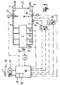
- Fig. 1 shows in the form of a block diagram of a reciprocating internal combustion engine 1 with associated turbocharger 2 to increase the charge pressure of the combustion air is above its exhaust tract 3 with the supercharger turbine 4 of the turbocharger 2 in conjunction.
- a controllable Blow-off valve 5 is arranged in the exhaust system 3 in front of the supercharger 4 .
- the piston internal combustion engine 1 is also available with its air supply tract 6 with the compressor 7 of the turbocharger 2 in conjunction.
- it is a throttle-controlled piston internal combustion engine, in the air supply tract 6 on the pressure side of the charger. 7 a controllable throttle valve 8 is arranged.
- the fuel supply takes place, as schematically indicated here, for example via controllable injectors 9, via the fuel in the individual leading to the cylinders air intake ducts is injected.
- controllable injectors 9 via the fuel in the individual leading to the cylinders air intake ducts is injected.
- the detail described below Method is applicable to all forms of fuel supply, so also for the direct fuel injection.
- the piston internal combustion engine 1 is associated with a motor controller 10, which supplies all measured values relevant for engine operation and all of which are required for engine operation Signals issued after appropriate processing become.
- the reciprocating internal combustion engine with its control are those control and regulation interventions as known provided and therefore not described, for normal operation the reciprocating internal combustion engine are necessary. Below are only described the tax and regulatory relationships that for carrying out the method according to the invention for boost pressure control required are.
- a pressure transmitter 11 is arranged in the air supply tract 6, its measured value in a computing unit 12 both as an absolute value as well as after differentiation as charge pressure gradient dp / dt is detected, with both values separately from the engine control 10 are available.
- the throttle valve 8 with its associated actuator has furthermore, an encoder 8.1, via which the respective throttle position ⁇ can be detected.
- an encoder 8.1 via which the respective throttle position ⁇ can be detected.
- the absolute value of the respective throttle position ascertained and by differentiation too the throttle gradient d ⁇ / dt determined. Also these two Values are assigned to the motor control as separate values Available.
- the load request is supplied to the motor control via a pedal 14, via a corresponding unit 15 on the one hand actual pedal position ⁇ and on the other hand, the temporal Change of pedal position, d. H. the pedal gradient d ⁇ / dt outputs as input to the motor control. The value the pedal gradient is still over one of the engine control 10 associated low-pass filter 16 taken into account.
- crankshaft speed the reciprocating internal combustion engine 1 in usually detected by a transmitter 17 and the engine control 10th made available.
- a throttle-free controlled reciprocating internal combustion engine eliminates the throttle valve 8 shown in the block diagram with their control, since the gas exchange valves over fully variable controllable valve trains, such as electromagnetic Actuators are actuated via the motor control 10 are controlled directly. By influencing the Opening times, but also the opening time of the gas exchange valves can work in the same way as over a throttle the load of the reciprocating internal combustion engine are controlled.
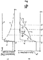
- Fig. 2 the preferred embodiment of the method for two different load states in their procedural linkage of the detection of a low-pass filtered pedal gradient with the detection of the respectively associated boost pressure gradient is shown.
- Fig. 2 shows the diagram I in the curve a in percent the course of the pedal value and identical to the value of the associated throttle position. The driver is fully depressed for an acceleration process at time t 0 within a short time, the pedal 14, so that the pedal 14 is held at full throttle position.
- the curve b shows the associated pedal gradient. Since the pedal angle is traversed from the pedal output position at t 0 to the end position at time t 1 in a very short time, results for the Pedalgradienten, as shown in the curve b, a steep rise, with reaching the Pedalend too and thus the end of Pedal movement immediately drops to zero again. About the motor controller 10 of this pedal gradient is detected, as will be described in more detail below, held as a measured value. This measured value is applied to the motor control as a low-pass filtered signal, as shown in the curve c, so that, starting from the originally large pedal gradients, the value decreases with increasing time and thus a change in the predetermined limit for the load-proportional gradient is possible.
- the pressure first increases linearly. Thereafter, there is a further increase in the pressure in the intake by the run-up of the turbocharger. In a first load case, this is done quickly, so that the boost pressure continues to rise quickly, with conventional control according to the Kurvenast e 2 with a very steep course in the last part before reaching the target pressure. In a second load case, a strongly delayed response of the turbocharger is shown. Here, the further pressure rise but then is delayed, without the intervention according to the described method due to the feedback of the system is also very steep corresponding to curve f 2.
- This increase over time can be considered a gradient be detected.
- a stored in the engine control map is, as described above, given a maximum allowable boost pressure gradient, which is represented by the slope of the dashed curve branches e 1 and f 1 . If the gradient of the curve e or f) reaches the limit value, shown at the time t 1 or t 3 , the charge pressure buildup is counteracted to the extent that a guided charge pressure curve corresponding to the Curve load e 1 or f 1 results.
Landscapes
- Engineering & Computer Science (AREA)
- Chemical & Material Sciences (AREA)
- Combustion & Propulsion (AREA)
- Mechanical Engineering (AREA)
- General Engineering & Computer Science (AREA)
- Supercharger (AREA)
- Output Control And Ontrol Of Special Type Engine (AREA)
- Combined Controls Of Internal Combustion Engines (AREA)
- Electrical Control Of Air Or Fuel Supplied To Internal-Combustion Engine (AREA)
Applications Claiming Priority (3)
| Application Number | Priority Date | Filing Date | Title |
|---|---|---|---|
| DE19960166 | 1999-12-14 | ||
| DE19960166A DE19960166A1 (de) | 1999-12-14 | 1999-12-14 | Verfahren zur Regelung des Ladedrucks an einer Kolbenbrennkraftmaschine mit Turbolader |
| PCT/EP2000/012144 WO2001044641A2 (de) | 1999-12-14 | 2000-12-02 | Verfahren zur regelung des ladedrucks an einer kolbenbrennkraftmaschine mit turbolader |
Publications (2)
| Publication Number | Publication Date |
|---|---|
| EP1183452A2 EP1183452A2 (de) | 2002-03-06 |
| EP1183452B1 true EP1183452B1 (de) | 2005-05-25 |
Family
ID=7932557
Family Applications (1)
| Application Number | Title | Priority Date | Filing Date |
|---|---|---|---|
| EP00991580A Expired - Lifetime EP1183452B1 (de) | 1999-12-14 | 2000-12-02 | Verfahren zur regelung des ladedrucks an einer kolbenbrennkraftmaschine mit turbolader |
Country Status (6)
| Country | Link |
|---|---|
| US (1) | US6615584B2 (enExample) |
| EP (1) | EP1183452B1 (enExample) |
| JP (1) | JP2003517137A (enExample) |
| AT (1) | ATE296400T1 (enExample) |
| DE (2) | DE19960166A1 (enExample) |
| WO (1) | WO2001044641A2 (enExample) |
Families Citing this family (28)
| Publication number | Priority date | Publication date | Assignee | Title |
|---|---|---|---|---|
| LU90848B1 (en) * | 2001-10-15 | 2003-04-16 | Delphi Tchnologies Inc | Method for controlling an exhaust-gas turbocharger with a variable turbine geometry |
| JP2005180226A (ja) * | 2003-12-17 | 2005-07-07 | Hitachi Constr Mach Co Ltd | 建設機械のエンジン給気系異常検出装置及び異常検出方法 |
| US6904353B1 (en) * | 2003-12-18 | 2005-06-07 | Honeywell International, Inc. | Method and system for sliding mode control of a turbocharger |
| JP4557205B2 (ja) * | 2004-02-20 | 2010-10-06 | 株式会社小松製作所 | 油圧機器の制御装置 |
| DE102004061424A1 (de) | 2004-12-21 | 2006-06-29 | Daimlerchrysler Ag | Kühleinrichtung in einem Brennstoffzellen-Fahrzeug |
| US7467614B2 (en) | 2004-12-29 | 2008-12-23 | Honeywell International Inc. | Pedal position and/or pedal change rate for use in control of an engine |
| AU302969S (en) * | 2005-02-08 | 2005-08-31 | Txs Pty Ltd | Blow off valve |
| US7389773B2 (en) | 2005-08-18 | 2008-06-24 | Honeywell International Inc. | Emissions sensors for fuel control in engines |
| DE102006009864A1 (de) * | 2006-03-03 | 2007-09-06 | Dr.Ing.H.C. F. Porsche Ag | Verfahren und Steuergerät zur Einstellung eines Turbinenströmungsquerschnitts eines Turboladers |
| US8060290B2 (en) | 2008-07-17 | 2011-11-15 | Honeywell International Inc. | Configurable automotive controller |
| US8620461B2 (en) | 2009-09-24 | 2013-12-31 | Honeywell International, Inc. | Method and system for updating tuning parameters of a controller |
| DE102009055734A1 (de) * | 2009-11-26 | 2011-06-01 | Fev Motorentechnik Gmbh | Multifuel-Diesel-Verbrennungskraftmaschine |
| US8504175B2 (en) | 2010-06-02 | 2013-08-06 | Honeywell International Inc. | Using model predictive control to optimize variable trajectories and system control |
| US9677493B2 (en) | 2011-09-19 | 2017-06-13 | Honeywell Spol, S.R.O. | Coordinated engine and emissions control system |
| US9650934B2 (en) | 2011-11-04 | 2017-05-16 | Honeywell spol.s.r.o. | Engine and aftertreatment optimization system |
| US20130111905A1 (en) | 2011-11-04 | 2013-05-09 | Honeywell Spol. S.R.O. | Integrated optimization and control of an engine and aftertreatment system |
| JP5773026B2 (ja) | 2013-04-30 | 2015-09-02 | トヨタ自動車株式会社 | 過給機付きエンジンの制御装置 |
| DE102014210026B4 (de) * | 2014-05-26 | 2025-10-09 | Volkswagen Aktiengesellschaft | Verfahren und Steuerung zum Steuern eines Aufladungssystems für eine Verbrennungskraftmaschine |
| EP3051367B1 (en) | 2015-01-28 | 2020-11-25 | Honeywell spol s.r.o. | An approach and system for handling constraints for measured disturbances with uncertain preview |
| EP3056706A1 (en) | 2015-02-16 | 2016-08-17 | Honeywell International Inc. | An approach for aftertreatment system modeling and model identification |
| EP3091212A1 (en) | 2015-05-06 | 2016-11-09 | Honeywell International Inc. | An identification approach for internal combustion engine mean value models |
| EP3125052B1 (en) | 2015-07-31 | 2020-09-02 | Garrett Transportation I Inc. | Quadratic program solver for mpc using variable ordering |
| US10272779B2 (en) | 2015-08-05 | 2019-04-30 | Garrett Transportation I Inc. | System and approach for dynamic vehicle speed optimization |
| US10415492B2 (en) | 2016-01-29 | 2019-09-17 | Garrett Transportation I Inc. | Engine system with inferential sensor |
| US10036338B2 (en) | 2016-04-26 | 2018-07-31 | Honeywell International Inc. | Condition-based powertrain control system |
| US10124750B2 (en) | 2016-04-26 | 2018-11-13 | Honeywell International Inc. | Vehicle security module system |
| US11199120B2 (en) | 2016-11-29 | 2021-12-14 | Garrett Transportation I, Inc. | Inferential flow sensor |
| US11057213B2 (en) | 2017-10-13 | 2021-07-06 | Garrett Transportation I, Inc. | Authentication system for electronic control unit on a bus |
Family Cites Families (8)
| Publication number | Priority date | Publication date | Assignee | Title |
|---|---|---|---|---|
| US4928489A (en) * | 1987-12-29 | 1990-05-29 | Honda Giken Kogyo K.K. | Supercharging pressure control method for turbocharged internal combustion engines |
| US4961319A (en) * | 1988-12-22 | 1990-10-09 | Chrysler Corporation | Method of turbocharger control |
| DE4025901C1 (enExample) * | 1990-08-16 | 1992-01-30 | Mercedes-Benz Aktiengesellschaft, 7000 Stuttgart, De | |
| US5228292A (en) * | 1990-08-16 | 1993-07-20 | Mercedes-Benz Ag | Arrangement for controlling the boost pressure in an internal-combustion engine supercharged by an exhaust-gas turbocharger of adjustable turbine geometry |
| DE69433853T2 (de) * | 1993-12-28 | 2005-07-14 | Hitachi, Ltd. | Verfahren und Vorrichtung zur Steuerung einer Brennkraftmaschine |
| IT1284345B1 (it) | 1996-01-26 | 1998-05-18 | Fiat Ricerche | Metodo e unita' di controllo della pressione di sovralimentazione per un motore turbodiesel con turbina a geometria variabile |
| DE19750445C1 (de) * | 1997-11-14 | 1999-06-24 | Daimler Chrysler Ag | Verfahren zur Steuerung eines VTG-Abgasturboladers |
| DE19844214C1 (de) * | 1998-09-26 | 1999-05-27 | Daimler Chrysler Ag | Verfahren zur Regelung oder Steuerung einer aufgeladenen Brennkraftmaschine |
-
1999
- 1999-12-14 DE DE19960166A patent/DE19960166A1/de not_active Withdrawn
-
2000
- 2000-12-02 US US09/913,395 patent/US6615584B2/en not_active Expired - Fee Related
- 2000-12-02 JP JP2001545706A patent/JP2003517137A/ja active Pending
- 2000-12-02 EP EP00991580A patent/EP1183452B1/de not_active Expired - Lifetime
- 2000-12-02 DE DE50010404T patent/DE50010404D1/de not_active Expired - Lifetime
- 2000-12-02 AT AT00991580T patent/ATE296400T1/de not_active IP Right Cessation
- 2000-12-02 WO PCT/EP2000/012144 patent/WO2001044641A2/de not_active Ceased
Also Published As
| Publication number | Publication date |
|---|---|
| JP2003517137A (ja) | 2003-05-20 |
| WO2001044641A3 (de) | 2001-12-13 |
| US6615584B2 (en) | 2003-09-09 |
| US20020134080A1 (en) | 2002-09-26 |
| DE50010404D1 (de) | 2005-06-30 |
| EP1183452A2 (de) | 2002-03-06 |
| ATE296400T1 (de) | 2005-06-15 |
| DE19960166A1 (de) | 2001-06-21 |
| WO2001044641A2 (de) | 2001-06-21 |
Similar Documents
| Publication | Publication Date | Title |
|---|---|---|
| EP1183452B1 (de) | Verfahren zur regelung des ladedrucks an einer kolbenbrennkraftmaschine mit turbolader | |
| DE10329763B4 (de) | Koordinierte Regelung einer elektronischen Drosselklappe und eines Turboladers mit variabler Geometrie in ladedruckverstärkten und stöchiometrisch betriebenen Ottomotoren | |
| DE19531871C1 (de) | Verfahren zur Regelung des Ladedrucks bei einer mittels eines Abgasturboladers mit verstellbarer Turbinengeometrie aufgeladenen Brennkraftmaschine | |
| DE3020493A1 (de) | Verfahren zum steuern des ansaugluftdurchsatzes bei einem brennkraftmotor | |
| EP0831216A2 (de) | Verfahren zum Betreiben einer Motorbremse und Vorrichtung zur Durchführung des Verfahrens | |
| DE102016011078A1 (de) | Steuerungsvorrichtung für einen Motor, Verfahren zum Steuern eines Motors und Computerprogrammprodukt | |
| DE4330368A1 (de) | Verfahren und Vorrichtung zur Steuerung der Antriebsleistung eines Fahrzeugs | |
| DE2751125A1 (de) | Steuereinrichtung fuer eine brennkraftmaschine | |
| DE112011104717B4 (de) | Steuerungsvorrichtung für eine Verbrennungskraftmaschine mit Auflader | |
| DE102010043897B4 (de) | Verfahren und Vorrichtung zum Betreiben eines Verbrennungsmotors | |
| DE102008018193B3 (de) | Verfahren zur Luftmassenstromregelung | |
| EP3594480B1 (de) | Verfahren zur steuerung eines aufladungssystems | |
| DE3939754A1 (de) | Verfahren zur regelung des druckes in der ansaugleitung vor den einlassventilen bei einer mittels eines abgasturboladers aufgeladenen luftverdichtenden einspritzbrennkraftmaschine | |
| DE2943950C2 (enExample) | ||
| DE3106579A1 (de) | Einrichtung zum bestimmen von steuergroessen einer mit aufladung betriebenen brennkraftmaschine | |
| DE10328786A1 (de) | Verfahren zum Betreiben eines Kraftfahrzeuges | |
| DE102008042783A1 (de) | Verfahren und Vorrichtung zum Betreiben einer Antriebseinheit | |
| EP1830049B1 (de) | Verfahren und Steuergerät zur Einstellung eines Turbinenströmungsquerschnitts eines Turboladers | |
| DE60024852T2 (de) | Verfahren zum regeln von drehmomentänderungen in brennkraftmaschinen und brennkraftmaschine mit entsprechender regelung | |
| DE102011081949B4 (de) | Verfahren und Vorrichtung zur Durchführung einer Regelung, insbesondere zum Einsatz in einem Kraftfahrzeug | |
| WO1991008922A1 (de) | System zur elektronischen steuerung und/oder regelung der leistung einer brennkraftmaschine eines kraftfahrzeugs | |
| DE4426972B4 (de) | Verfahren und Vorrichtung zur Steuerung einer Brennkraftmaschine | |
| DE3928833C2 (enExample) | ||
| DE102004061110B4 (de) | Verfahren zum Betreiben einer Brennkraftmaschine | |
| EP0952324B1 (de) | Anordnung zum Wiederaufbauen des Drehmoments einer aufgeladenen Brennkraftmaschine nach einem ASR-Eingriff |
Legal Events
| Date | Code | Title | Description |
|---|---|---|---|
| PUAI | Public reference made under article 153(3) epc to a published international application that has entered the european phase |
Free format text: ORIGINAL CODE: 0009012 |
|
| 17P | Request for examination filed |
Effective date: 20010818 |
|
| AK | Designated contracting states |
Kind code of ref document: A2 Designated state(s): AT BE CH CY DE DK ES FI FR GB GR IE IT LI LU MC NL PT SE TR |
|
| AX | Request for extension of the european patent |
Free format text: AL;LT;LV;MK;RO;SI |
|
| 17Q | First examination report despatched |
Effective date: 20030909 |
|
| GRAP | Despatch of communication of intention to grant a patent |
Free format text: ORIGINAL CODE: EPIDOSNIGR1 |
|
| GRAS | Grant fee paid |
Free format text: ORIGINAL CODE: EPIDOSNIGR3 |
|
| GRAA | (expected) grant |
Free format text: ORIGINAL CODE: 0009210 |
|
| AK | Designated contracting states |
Kind code of ref document: B1 Designated state(s): AT BE CH CY DE DK ES FI FR GB GR IE IT LI LU MC NL PT SE TR |
|
| PG25 | Lapsed in a contracting state [announced via postgrant information from national office to epo] |
Ref country code: IT Free format text: LAPSE BECAUSE OF FAILURE TO SUBMIT A TRANSLATION OF THE DESCRIPTION OR TO PAY THE FEE WITHIN THE PRESCRIBED TIME-LIMIT;WARNING: LAPSES OF ITALIAN PATENTS WITH EFFECTIVE DATE BEFORE 2007 MAY HAVE OCCURRED AT ANY TIME BEFORE 2007. THE CORRECT EFFECTIVE DATE MAY BE DIFFERENT FROM THE ONE RECORDED. Effective date: 20050525 Ref country code: GB Free format text: LAPSE BECAUSE OF FAILURE TO SUBMIT A TRANSLATION OF THE DESCRIPTION OR TO PAY THE FEE WITHIN THE PRESCRIBED TIME-LIMIT Effective date: 20050525 Ref country code: IE Free format text: LAPSE BECAUSE OF FAILURE TO SUBMIT A TRANSLATION OF THE DESCRIPTION OR TO PAY THE FEE WITHIN THE PRESCRIBED TIME-LIMIT Effective date: 20050525 Ref country code: FI Free format text: LAPSE BECAUSE OF FAILURE TO SUBMIT A TRANSLATION OF THE DESCRIPTION OR TO PAY THE FEE WITHIN THE PRESCRIBED TIME-LIMIT Effective date: 20050525 Ref country code: NL Free format text: LAPSE BECAUSE OF FAILURE TO SUBMIT A TRANSLATION OF THE DESCRIPTION OR TO PAY THE FEE WITHIN THE PRESCRIBED TIME-LIMIT Effective date: 20050525 Ref country code: TR Free format text: LAPSE BECAUSE OF FAILURE TO SUBMIT A TRANSLATION OF THE DESCRIPTION OR TO PAY THE FEE WITHIN THE PRESCRIBED TIME-LIMIT Effective date: 20050525 |
|
| REG | Reference to a national code |
Ref country code: GB Ref legal event code: FG4D Free format text: NOT ENGLISH |
|
| REG | Reference to a national code |
Ref country code: CH Ref legal event code: EP |
|
| REG | Reference to a national code |
Ref country code: IE Ref legal event code: FG4D Free format text: LANGUAGE OF EP DOCUMENT: GERMAN |
|
| REF | Corresponds to: |
Ref document number: 50010404 Country of ref document: DE Date of ref document: 20050630 Kind code of ref document: P |
|
| PG25 | Lapsed in a contracting state [announced via postgrant information from national office to epo] |
Ref country code: GR Free format text: LAPSE BECAUSE OF FAILURE TO SUBMIT A TRANSLATION OF THE DESCRIPTION OR TO PAY THE FEE WITHIN THE PRESCRIBED TIME-LIMIT Effective date: 20050825 Ref country code: DK Free format text: LAPSE BECAUSE OF FAILURE TO SUBMIT A TRANSLATION OF THE DESCRIPTION OR TO PAY THE FEE WITHIN THE PRESCRIBED TIME-LIMIT Effective date: 20050825 Ref country code: SE Free format text: LAPSE BECAUSE OF FAILURE TO SUBMIT A TRANSLATION OF THE DESCRIPTION OR TO PAY THE FEE WITHIN THE PRESCRIBED TIME-LIMIT Effective date: 20050825 |
|
| PG25 | Lapsed in a contracting state [announced via postgrant information from national office to epo] |
Ref country code: ES Free format text: LAPSE BECAUSE OF FAILURE TO SUBMIT A TRANSLATION OF THE DESCRIPTION OR TO PAY THE FEE WITHIN THE PRESCRIBED TIME-LIMIT Effective date: 20050905 |
|
| PG25 | Lapsed in a contracting state [announced via postgrant information from national office to epo] |
Ref country code: PT Free format text: LAPSE BECAUSE OF FAILURE TO SUBMIT A TRANSLATION OF THE DESCRIPTION OR TO PAY THE FEE WITHIN THE PRESCRIBED TIME-LIMIT Effective date: 20051027 |
|
| NLV1 | Nl: lapsed or annulled due to failure to fulfill the requirements of art. 29p and 29m of the patents act | ||
| PG25 | Lapsed in a contracting state [announced via postgrant information from national office to epo] |
Ref country code: CY Free format text: LAPSE BECAUSE OF FAILURE TO SUBMIT A TRANSLATION OF THE DESCRIPTION OR TO PAY THE FEE WITHIN THE PRESCRIBED TIME-LIMIT Effective date: 20051202 Ref country code: AT Free format text: LAPSE BECAUSE OF NON-PAYMENT OF DUE FEES Effective date: 20051202 |
|
| GBV | Gb: ep patent (uk) treated as always having been void in accordance with gb section 77(7)/1977 [no translation filed] |
Effective date: 20050525 |
|
| REG | Reference to a national code |
Ref country code: IE Ref legal event code: FD4D |
|
| PG25 | Lapsed in a contracting state [announced via postgrant information from national office to epo] |
Ref country code: CH Free format text: LAPSE BECAUSE OF NON-PAYMENT OF DUE FEES Effective date: 20051231 Ref country code: MC Free format text: LAPSE BECAUSE OF NON-PAYMENT OF DUE FEES Effective date: 20051231 Ref country code: LI Free format text: LAPSE BECAUSE OF NON-PAYMENT OF DUE FEES Effective date: 20051231 Ref country code: BE Free format text: LAPSE BECAUSE OF NON-PAYMENT OF DUE FEES Effective date: 20051231 Ref country code: LU Free format text: LAPSE BECAUSE OF NON-PAYMENT OF DUE FEES Effective date: 20051231 |
|
| PLBE | No opposition filed within time limit |
Free format text: ORIGINAL CODE: 0009261 |
|
| STAA | Information on the status of an ep patent application or granted ep patent |
Free format text: STATUS: NO OPPOSITION FILED WITHIN TIME LIMIT |
|
| 26N | No opposition filed |
Effective date: 20060228 |
|
| EN | Fr: translation not filed | ||
| REG | Reference to a national code |
Ref country code: CH Ref legal event code: PL |
|
| BERE | Be: lapsed |
Owner name: FEV MOTORENTECHNIK G.M.B.H. Effective date: 20051231 |
|
| PG25 | Lapsed in a contracting state [announced via postgrant information from national office to epo] |
Ref country code: FR Free format text: LAPSE BECAUSE OF NON-PAYMENT OF DUE FEES Effective date: 20051231 |
|
| PG25 | Lapsed in a contracting state [announced via postgrant information from national office to epo] |
Ref country code: FR Free format text: LAPSE BECAUSE OF NON-PAYMENT OF DUE FEES Effective date: 20050525 |
|
| PGFP | Annual fee paid to national office [announced via postgrant information from national office to epo] |
Ref country code: DE Payment date: 20091222 Year of fee payment: 10 |
|
| REG | Reference to a national code |
Ref country code: DE Ref legal event code: R119 Ref document number: 50010404 Country of ref document: DE Effective date: 20110701 |
|
| PG25 | Lapsed in a contracting state [announced via postgrant information from national office to epo] |
Ref country code: DE Free format text: LAPSE BECAUSE OF NON-PAYMENT OF DUE FEES Effective date: 20110701 |