EP1182972B1 - Osteosynthetische knochenplatte - Google Patents
Osteosynthetische knochenplatte Download PDFInfo
- Publication number
- EP1182972B1 EP1182972B1 EP00926626A EP00926626A EP1182972B1 EP 1182972 B1 EP1182972 B1 EP 1182972B1 EP 00926626 A EP00926626 A EP 00926626A EP 00926626 A EP00926626 A EP 00926626A EP 1182972 B1 EP1182972 B1 EP 1182972B1
- Authority
- EP
- European Patent Office
- Prior art keywords
- plate
- bone
- compression
- struts
- brace
- Prior art date
- Legal status (The legal status is an assumption and is not a legal conclusion. Google has not performed a legal analysis and makes no representation as to the accuracy of the status listed.)
- Expired - Lifetime
Links
- 210000000988 bone and bone Anatomy 0.000 title claims abstract description 142
- 230000001097 osteosynthetic effect Effects 0.000 title claims abstract description 13
- 230000006835 compression Effects 0.000 claims abstract description 54
- 238000007906 compression Methods 0.000 claims abstract description 54
- 239000012634 fragment Substances 0.000 claims abstract description 38
- 206010017076 Fracture Diseases 0.000 claims description 42
- 208000010392 Bone Fractures Diseases 0.000 claims description 25
- 208000006153 Mandibular Fractures Diseases 0.000 claims description 4
- RTAQQCXQSZGOHL-UHFFFAOYSA-N Titanium Chemical compound [Ti] RTAQQCXQSZGOHL-UHFFFAOYSA-N 0.000 claims description 3
- 229910052719 titanium Inorganic materials 0.000 claims description 3
- 239000010936 titanium Substances 0.000 claims description 3
- 239000000463 material Substances 0.000 claims description 2
- 206010023149 Jaw fracture Diseases 0.000 description 4
- 230000035876 healing Effects 0.000 description 4
- 240000003517 Elaeocarpus dentatus Species 0.000 description 3
- 210000005036 nerve Anatomy 0.000 description 3
- 210000003128 head Anatomy 0.000 description 2
- 208000026817 47,XYY syndrome Diseases 0.000 description 1
- 208000024779 Comminuted Fractures Diseases 0.000 description 1
- 230000002159 abnormal effect Effects 0.000 description 1
- 230000003042 antagnostic effect Effects 0.000 description 1
- 238000004519 manufacturing process Methods 0.000 description 1
- 230000003340 mental effect Effects 0.000 description 1
- 230000004048 modification Effects 0.000 description 1
- 238000012986 modification Methods 0.000 description 1
- 230000035515 penetration Effects 0.000 description 1
- 239000007787 solid Substances 0.000 description 1
- 238000001356 surgical procedure Methods 0.000 description 1
- 238000011144 upstream manufacturing Methods 0.000 description 1
Images


Classifications
-
- A—HUMAN NECESSITIES
- A61—MEDICAL OR VETERINARY SCIENCE; HYGIENE
- A61B—DIAGNOSIS; SURGERY; IDENTIFICATION
- A61B17/00—Surgical instruments, devices or methods
- A61B17/56—Surgical instruments or methods for treatment of bones or joints; Devices specially adapted therefor
- A61B17/58—Surgical instruments or methods for treatment of bones or joints; Devices specially adapted therefor for osteosynthesis, e.g. bone plates, screws or setting implements
- A61B17/68—Internal fixation devices, including fasteners and spinal fixators, even if a part thereof projects from the skin
- A61B17/80—Cortical plates, i.e. bone plates; Instruments for holding or positioning cortical plates, or for compressing bones attached to cortical plates
- A61B17/8085—Cortical plates, i.e. bone plates; Instruments for holding or positioning cortical plates, or for compressing bones attached to cortical plates with pliable or malleable elements or having a mesh-like structure, e.g. small strips
-
- A—HUMAN NECESSITIES
- A61—MEDICAL OR VETERINARY SCIENCE; HYGIENE
- A61B—DIAGNOSIS; SURGERY; IDENTIFICATION
- A61B17/00—Surgical instruments, devices or methods
- A61B17/56—Surgical instruments or methods for treatment of bones or joints; Devices specially adapted therefor
- A61B17/58—Surgical instruments or methods for treatment of bones or joints; Devices specially adapted therefor for osteosynthesis, e.g. bone plates, screws or setting implements
- A61B17/68—Internal fixation devices, including fasteners and spinal fixators, even if a part thereof projects from the skin
- A61B17/80—Cortical plates, i.e. bone plates; Instruments for holding or positioning cortical plates, or for compressing bones attached to cortical plates
- A61B17/8004—Cortical plates, i.e. bone plates; Instruments for holding or positioning cortical plates, or for compressing bones attached to cortical plates with means for distracting or compressing the bone or bones
-
- A—HUMAN NECESSITIES
- A61—MEDICAL OR VETERINARY SCIENCE; HYGIENE
- A61B—DIAGNOSIS; SURGERY; IDENTIFICATION
- A61B17/00—Surgical instruments, devices or methods
- A61B17/56—Surgical instruments or methods for treatment of bones or joints; Devices specially adapted therefor
- A61B17/58—Surgical instruments or methods for treatment of bones or joints; Devices specially adapted therefor for osteosynthesis, e.g. bone plates, screws or setting implements
- A61B17/68—Internal fixation devices, including fasteners and spinal fixators, even if a part thereof projects from the skin
- A61B17/80—Cortical plates, i.e. bone plates; Instruments for holding or positioning cortical plates, or for compressing bones attached to cortical plates
- A61B17/8061—Cortical plates, i.e. bone plates; Instruments for holding or positioning cortical plates, or for compressing bones attached to cortical plates specially adapted for particular bones
- A61B17/8071—Cortical plates, i.e. bone plates; Instruments for holding or positioning cortical plates, or for compressing bones attached to cortical plates specially adapted for particular bones for the jaw
Definitions
- the present invention relates to an osteosynthetic bone plate for the treatment of fractures, especially for the reconstruction of mandibular fractures.
- Such bone plates are used intraoperatively to Fix bone fragments together. This can happen after accidents a bone is broken into bone fragments within an osteosynthesis may be required or within an orthognatic or maxillofaciale Surgical treatment for abnormal positions after an osteotomy and then correcting the position of the bone fragments.
- a bone plate With such a bone plate, one primarily bridges and fixes two Bone fragments with each other, each with a lot of the bone plate a bone fragment is detachably connected.
- the bone plates should be able to be bent to fit the bone geometry, but nevertheless ensure sufficient stability. Both demands stand basically antagonistic to each other.
- the bone plates should Building an interfragmentary pressure enable what is opposed by lying arrangement of so-called compression holes is achieved.
- this plate Due to its stiffness, this plate hardly matches the existing bone geometry customizable. An insufficiently bent jaw stiff plate, however, leads to the fact that the bone fragment is less anchored in the jaw is moved towards the plate, so dislocations occur. Even minor ones However, faults in the fracture area lead to the loss of the interfragmentary ones Support which results in greater mobility in the fracture area.
- the simple hole pattern on the plate also allows little variability for the Attachment to the bone fragments. For example also in PREIN, J. (Ed.): Manual of Internal Fixation in the Cranio-Facial Skeleton. Springer-Verlag Berlin and others 1998, p. 30, become single-lined straight or arched Bone plates with compression holes for the treatment of fractured Lower jaws shown, which have a thickness of 1.65mm or 2.0mm and for Bone screws designed with an external thread diameter of 2.4mm are.
- Thinner bone plates e.g. the thickness between 0.5mm and 0.9mm, which is better to bend are known from craniofacial applications (cf. PREIN, op. Cit., P. 28).
- different configurations e.g. as an L-plate, Y-plate, T-plate, H-plate, X-plate, double-Y-plate or frame plate, developed.
- bone screws with an external thread diameter are used from 1.0mm to 2.0mm.
- these bone plates have no compression holes, just simple cylindrical screw holes with countersinks for partial mounting of the screw head.
- it was previously thought for the establishment of an interfacmentary Pressure is a greater plate thickness, e.g. 1.65mm or 2.0mm required.
- the invention is based on bone plates, a bone plate especially for the treatment of lower jaw fractures that create due to easier deformability well to the given contour of the bone fragments can bend, but still a secure positionally stable fixation of the Bone fragments guaranteed. That on the one hand, the bone plate must be good be deformable and on the other hand have sufficient rigidity. In addition, the bone plate should have compression holes in order to Promote bone healing an interfragmentary pressure - in the sense of a Compression osteosynthesis - to be able to produce. Furthermore, the one to be created Bone plate do not squeeze the nerve emerging from the lower jaw and in the case of comminuted fractures, small bone fragments should also be attached individually to the Bone plate can be fixed. Finally, the bone plate needs to be Apply with conventional bone screws and in efficiently Have the series produced.
- the osteosynthetic bone plate is used to treat fractures, in particular for the reconstruction of mandibular fractures.
- the plate has elongated holes Compression holes with eccentric countersinks. Leave on the plate a longitudinal and a transverse axis as well as a top and a bottom of the plate define, the latter facing the bone fragments.
- the Bone plate consists of a compression part, which two at least in the has plate struts extending substantially parallel to the longitudinal axis. Both Plate struts are connected to each other by bridge webs, which the Cut the longitudinal axis.
- a plate strut has at least one of the outer flanks of the compression part one eye, the other eyes in front of it could be.
- An eye is preferably arranged on both outer flanks.
- the bone plate according to the invention have the compression holes with its longitudinal extension an orientation in the direction of the strut axis or take an angle ⁇ 0 ° to the strut axis and point at the Eccentric countersinks on the top of the plate.
- the compression part attach connecting bridges to the eyes, which soften on the strut axes extend.
- There is a fixing hole in each of the plate links intended to accommodate a bone screw.
- the connecting bridges between the eyes are wider than that connecting webs leading to the plate links. Own on the top of the plate the fixing holes a counterbore for partially recessed reception of the Heads of the bone screws.
- There are preferably two on the bone plate Bridges are provided that are symmetrical or asymmetrical to the transverse axis run. With a symmetrical arrangement of the bridges, extend both bridges bridge laterally from the outer flank of one eye one strut axis towards the outer flank of the opposite eye on the other strut axis. With an asymmetrical arrangement of the Bridge bridges are deviating from one bridge bridge to the transverse axis and seen from this, in front of the pair of eyes that focus on the lie opposite both strut axes.
- the bone plate has a material thickness in the range of 0.5mm to 1.5mm and is preferably made of grade 1 or grade 2 titanium Compression holes and bone screws inserted in the fixing holes are intended for monocortical screwing to the bone fragments.
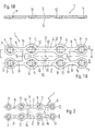
- the bone plate 1 which is constructed symmetrically to the longitudinal axis X and to the transverse axis Y, has two plate struts 2 running parallel to the longitudinal axis X and spaced apart from one another.
- the plate struts 2 extend on the strut axes Z.
- each plate strut 2 ends with a plate-shaped plate member 3 , in the middle of which a cylindrical fixing hole 4 is provided, which has a countersink 7 on the plate top 5 for partially recessed reception of a screw head.
- the fixing hole 4 opens out cylindrically.
- a connecting web 8 extends from the plate members 3 to the transverse axis Y on the strut axes Z.
- the four connecting webs 8 each connect to an eye 9 of the compression part 10 of the bone plate 1 .
- each eye 9 there is a conventional elongated compression hole 11 , the longitudinal extension of which lies on the strut axis Z.
- the individual compression hole 11 On the part of the transverse axis Y , the individual compression hole 11 has a countersink 12 on the top side 5 of the plate, which countersink in the compression hole 11 with increasing distance from the transverse axis Y.
- a bone screw quasi eccentric used in the compression hole 11 with penetration is urged her head into the compression hole 11 in a known manner to the transverse axis Y towards and in this case takes the screwed bone fragment.
- the connecting web 13 running on the respective strut axis Z , which connects both eyes 9 to one another.
- the connecting webs 13 have a greater width than the connecting webs 8 and therefore also have a higher rigidity.
- the two plate struts 2 are connected to one another by two bridge webs 14 which are symmetrical to the transverse axis Y.
- the bridge webs 14 each extend laterally from the opening of the connecting web 8 to one eye 9 on one strut axis Z to the opening of the connecting web 8 at the opposite eye 9 on the other strut axis Z.
- the bone plate 1 By designing the 1.0 mm thick bone plate 1, for example Titanium grade 1 or grade 2 with two plate struts 2 and the bridge webs 14 , the bone plate 1 can be bent to fit the respective geometry of the bone fragments and is at the same time of sufficient rigidity for the positionally stable fixation of the bone fragments.
- the modification compared to the bone plate 1 in FIG. 1 is that in the bone plate 1 shown here the bridge webs 14 connecting the two plate struts 2 are arranged asymmetrically to the transverse axis Y.
- the right bridge web 14 extends laterally unchanged from the opening of the connecting web 8 to an eye 9 on one strut axis Z to the opening of the connecting web 8 at the opposite eye 9 on the other strut axis Z.
- the left bridge web 14, however, is offset to the transverse axis Y ; this bridge web 14 extends laterally from before the junction of the connecting web 13 with an eye 9 on one strut axis Z to a position before the junction of the connecting web 13 with the opposite eye 9 on the other strut axis Z.
- a bone plate 1 configured in this way is primarily in the case of of the application for a paramedian fracture on the lower jaw, where the emerging nerve must not be pressed by a plate part (see the description of FIG. 7B).
- the bridge webs 14 each extend from the outer flank of one eye 9 on one strut axis Z to the outer flank of the opposite eye 9 on the other strut axis Z.
- An exemplary application of this bone plate 1 is shown in 6A.
- the special feature of this symmetrical embodiment compared to the basic variant according to FIG. 1 is that the two elongated compression holes 11 with the eyes 9 on the lower plate strut 2 do not extend in their longitudinal extent on the strut axis Z or parallel to the longitudinal axis X , but rather the angle ⁇ take in. This is useful if an interfragmentary pressure is to be built up from the lower plate strut 2 in an oblique direction to the longitudinal axis X in the case of a special course of fracture.
- the two figures illustrate the functional principle of compression osteosynthesis using an example of a bone plate 1 according to FIG. 3.
- the bone plate 1 is of the so-called mini-plate type.
- the bone screws 30 are introduced into the oblong-shaped compression holes 11 facing away from the countersinks 12 , ie, viewed on the respective plate strut 2 and on the associated strut axis Z, at the greatest possible distance from one another.
- the screw heads 31 of the bone screws 30 which are preferably monocortically screwed into the bone fragments, are further away from the fracture gap 22 and the transverse axis Y.
- FIG. 5B shows, with increasing screwing in of the bone screws 30 into the bone fragments 20, 21, the screw heads 31 - through the specially contoured countersinks 12 in the compression holes 11 - get into the countersinks 12 .
- the bone fragments 20, 21 hanging on the bone screws 30 are taken along in the direction of the transverse axis Y and the fracture gap 22 until finally the fracture gap 22 is closed and the bone fragments 20, 21 are joined together with compression.
Landscapes
- Health & Medical Sciences (AREA)
- Orthopedic Medicine & Surgery (AREA)
- Surgery (AREA)
- Life Sciences & Earth Sciences (AREA)
- Heart & Thoracic Surgery (AREA)
- Animal Behavior & Ethology (AREA)
- Engineering & Computer Science (AREA)
- Biomedical Technology (AREA)
- Neurology (AREA)
- Medical Informatics (AREA)
- Molecular Biology (AREA)
- Nuclear Medicine, Radiotherapy & Molecular Imaging (AREA)
- General Health & Medical Sciences (AREA)
- Public Health (AREA)
- Veterinary Medicine (AREA)
- Surgical Instruments (AREA)
- Materials For Medical Uses (AREA)
- Pharmaceuticals Containing Other Organic And Inorganic Compounds (AREA)
Description
- Frakturen in atrophischen Kiefern;
- instabilen Schräg-Frakturen;
- infizierten Unterkiefer-Frakturen;
- instabilen Kieferwinkel-Frakturen; und für
- Unterkiefer-Frakturen bei nicht-kooperativen Patienten.
- Figur 1A -
- eine symmetrische Knochenplatte mit 4 Kompressionslöchern und 4 zylindrischen Fixierlöchern in Draufsicht;
- Figur 1B -
- die Darstellung gemäss Figur 1A als Schnitt auf der Linie A-A;
- Figur 2 -
- eine asymmetrische Knochenplatte mit 4 Kompressionslöchern und 4 zylindrischen Fixierlöchern in Draufsicht;
- Figur 3 -
- eine symmetrische Knochenplatte mit 4 Kompressionslöchern in Draufsicht;
- Figur 4 -
- eine symmetrische Knochenplatte gemäss Figur 1A mit 2 winkling zur Längsachse orientierten Kompressionslöchern in Draufsicht;
- Figur 5A -
- die symmetrische Knochenplatte gemäss Figur 3 am Beginn einer Kompressions-Osteosynthese mit offenem Knochenspalt;
- Figur 5B -
- die Darstellung gemäss Figur 5A während der Kompressions-Osteosynthese mit geschlossenem Knochenspalt;
- Figur 6A -
- die symmetrische Knochenplatte gemäss Figur 3 bei einer Kieferwinkel-Fraktur lateral am Unterkiefer eingesetzt;
- Figur 6B -
- die symmetrische Knochenplatte gemäss Figur 1A bei einer Kieferwinkel-Fraktur lateral am Unterkiefer eingesetzt;
- Figur 7A -
- die symmetrische Knochenplatte gemäss Figur 1A bei einer Median-Fraktur frontal am Unterkiefer eingesetzt; und
- Figur 7B -
- die asymmetrische Knochenplatte gemäss Figur 2 bei einer Paramedian-Fraktur seitlich am Unterkiefer eingesetzt.
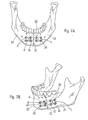
- Fig. 6A:
- Mit einer Knochenplatte 1 in der Konfiguration gemäss Fig. 3, welche nur das Kompressionsteil 10 aufweist, wird eine Kieferwinkel-Fraktur behandelt. Die mit vier Knochenschrauben 30 fixierte Knochenplatte 1 überbrückt den Frakturspalt 22 und verbindet als Knochenfragmente 20,21 den Corpus mandibulae mit dem Ramus mandibulae.
- Fig. 6B:
- Mit einer symmetrischen Knochenplatte 1 in der Konfiguration gemäss Fig. 1, welche das Kompressionsteil 10 und die sich darüber hinaus erstreckenden Anschlussstege 8 und die äusseren Plattenglieder 3 umfasst, wird ebenfalls eine Kieferwinkel-Fraktur behandelt. Über den Frakturspalt 22 verbunden sind wiederum als Knochenfragmente 20,21 der Corpus mandibulae mit dem Ramus mandibulae. Zusätzlich zu den vier Knochenschrauben 30 im Kompressionsteil 10 sind die Knochenfragmente 20,21 mit jeweils zwei in den äusseren Plattengliedern 3 eingesetzten Knochenschrauben 30 gesichert.
- Fig. 7A:
- Ebenfalls mit einer symmetrischen Knochenplatte 1 in der Konfiguration gemäss Fig. 1, welche das Kompressionsteil 10 und die sich darüber hinaus erstreckenden Anschlussstege 8 und die äusseren Plattenglieder 3 umfasst, wird eine Median-Fraktur am Unterkiefer be- handelt. Über den median liegenden Frakturspalt 22 sind als Knochenfragmente 20,21 zwei Teile des gebrochenen Corpus mandibulae miteinander verbunden. Auch hier sind zusätzlich zu den vier Knochenschrauben 30 im Kompressionsteil 10 die Knochenfragmente 20,21 mit den jeweils zwei in den äusseren Plattengliedern 3 eingesetzten Knochenschrauben 30 lagestabil fixiert.
- Fig. 7B:
- Zur gezeigten Behandlung einer Paramedian-Fraktur am Unterkiefer wird eine asymmetrischen Knochenplatte 1 in der Konfiguration gemäss Fig. 2 verwendet. Diese Knochenplatte 1 besteht aus dem Kompressionsteil 10, den sich darüber hinaus erstreckenden Anschlussstegen 8, den äusseren Plattengliedern 3 und den asymmetrisch angeordneten Brückenstegen 14 zwischen den beiden Plattenstreben 2. Mittels der Knochenplatte 1 sind über den paramedian liegenden Frakturspalt 22 als Knochenfragmente 20,21 zwei Teile des aussermittig gebrochenen Corpus mandibulae miteinander verbunden. Der austretende Nerv 40 (Foramen mentale) liegt frei und wird von keinem der Plattenteile gequetscht. Insgesamt sind die Knochenfragmente 20,21 jeweils mit vier Knochenschrauben 30 gesichert.
Claims (8)
- Osteosynthetische Knochenplatte (1) zur Behandlung von Frakturen, insbesondere zur Rekonstruktion von Unterkiefer-Frakturen, wobei die Knochenplatte (1):a) dazu bestimmt ist, mittels herkömmlichen Knochenschrauben (30), die Schraubenköpfe (31) haben, auf die nach dem Prinzip der Kompressions-Osteosynthese an einem Frakturspalt (22) zusammen zu fügenden Knochenfragmente (20,21) aufgeschraubt zu werden;b) langlochförmige Kompressionslöcher (11) mit exzentrischen Ansenkungen (12) aufweist;c) eine Längsachse (X) und eine Querachse (Y) besitzt; undd) eine Plattenoberseite (5) und eine den Knochenfragmenten (20,21) zugewandte Plattenunterseite (6) besitzt, dadurch gekennzeichnet, dasse) die Knochenplatte (1) aus einem Kompressionsteil (10) besteht, welches zwei zumindest im wesentlichen parallel zur Längsachse (X) verlaufende Plattenstreben (2) besitzt;f) die beiden Plattenstreben (2) durch Brückenstege (14) miteinander verbunden sind, welche die Längsachse (X) schneiden;g) eine Plattenstrebe (2) an einer der Aussenflanken oder an beiden Aussenflanken des Kompressionsteils (10) ein Auge (9) hat, dem weitere Augen ( 9 ) vorgelagert sein können;h) sich in den Augen ( 9 ) jeweils ein Kompressionsloch (11) befindet; undi) sich zwischen den auf einer Plattenstrebe (2) gelegenen Augen (9) jeweils ein Verbindungssteg (13) erstreckt, der die Querachse (Y) schneidetj) die Knochenplatte eine Materialstärke im Bereich von 0,5mm bis 1,5mm aufweist.
- Osteosynthetische Knochenplatte (1) nach Anspruch 1, dadurch gekennzeichnet, dass die Kompressionslöcher (11)a) mit ihrer Längserstreckung eine Orientierung in Richtung der Strebenachse (Z) haben; oderb) zur Strebenachse (Z) einen Winkel (α) 0° einnehmen; undc) an der Plattenoberseite (4) exzentrische Ansenkungen (12) aufweisen.
- Osteosynthetische Knochenplatte (1) nach Anspruch 1 oder 2, dadurch gekenntzeichnet, dassa) in Verlängerung des Kompressionsteils (10) an die Augen (9) Anschlussstege (8) ansetzen, welche sich auf den Strebenachsen (Z) erstrecken;b) sich am Ende der Anschlussstege (8) jeweils ein tellerförmiges Plattenglied ( 3 ) befindet, denen weitere durch Anschlussstege ( 8 ) verbundene Plattenglieder (3) vorgelagert sein können; undc) in den Plattengliedern (3) je ein Fixierloch (4) zur Aufnahme einer Knochenschraube (30) vorgesehen ist.
- Osteosynthetische Knochenplatte (1) nach Anspruch 3, dadurch gekennzeichnet, dassa) die Verbindungsstege (13) zwischen den Augen (9) von grösserer Breite sind als die zu den Plattengliedern (3) führenden Anschlussstege (8) und;b) die Fixierlöcher (4) auf der Plattenoberseite (5) eine Ansenkung (12) zur partiell versenkten Aufnahme der Köpfe (31) der Knochenschrauben (30) haben.
- Osteosynthetische Knochenplatte (1) nach einem,der Ansprüche 1 bis 4, dadurch gekennzeichnet, dass zwei Brückenstege (14) vorgesehen sind, die sich zur Querachse (Y) symmetrisch oder asymmetrisch erstrecken.
- Osteosynthetische Knochenplatte (1) nach Anspruch 5, dadurch gekennzeichnet, dassa) bei einer symmetrischen Anordnung der Brückenstege (14) sich beide Brückenstege (14) jeweils lateral von der Aussenflanke eines Auges (9) auf der einen Strebenachse (Z) hin zur Aussenflanke des gegenüber liegenden Auges (9) auf der anderen Strebenachse (Z) erstrecken; undb) bei einer asymmetrischen Anordnung der Brückenstege (14) abweichend ein Brückensteg (14) zur Querachse (Y) hin versetzt ist und von dieser aus betrachtet, vor dem Paar von Augen (9), die sich auf den beiden Strebenachsen (Z) gegenüber liegen, verläuft.
- Osteosynthetische Knochenplatte (1) nach einem der Ansprüche 1 bis 6, dadurch gekennzeichnet, dass diese aus Titan, vorzugsweise der Güte Grad 1 oder Grad 2, besteht.
- Osteosynthetische Knochenplatte (1) nach einem der Ansprüche 1 bis 7, dadurch gekennzeichnet, dass die in die Kompressionslöcher (11) und in die Fixierlöcher (4) eingesetzten Knochenschrauben (30) zum monokortikalen Verschrauben mit den Knochenfragmenten (20,21) vorgesehen sind,
Applications Claiming Priority (3)
| Application Number | Priority Date | Filing Date | Title |
|---|---|---|---|
| DE29909025U DE29909025U1 (de) | 1999-05-25 | 1999-05-25 | Osteosynthetische Knochenplatte |
| DE29909025U | 1999-05-25 | ||
| PCT/CH2000/000299 WO2000071031A1 (de) | 1999-05-25 | 2000-05-25 | Osteosynthetische knochenplatte |
Publications (2)
| Publication Number | Publication Date |
|---|---|
| EP1182972A1 EP1182972A1 (de) | 2002-03-06 |
| EP1182972B1 true EP1182972B1 (de) | 2003-10-15 |
Family
ID=8073857
Family Applications (1)
| Application Number | Title | Priority Date | Filing Date |
|---|---|---|---|
| EP00926626A Expired - Lifetime EP1182972B1 (de) | 1999-05-25 | 2000-05-25 | Osteosynthetische knochenplatte |
Country Status (7)
| Country | Link |
|---|---|
| US (2) | US6960211B1 (de) |
| EP (1) | EP1182972B1 (de) |
| JP (1) | JP2003530138A (de) |
| AT (1) | ATE251869T1 (de) |
| DE (2) | DE29909025U1 (de) |
| ES (1) | ES2207506T3 (de) |
| WO (1) | WO2000071031A1 (de) |
Cited By (2)
| Publication number | Priority date | Publication date | Assignee | Title |
|---|---|---|---|---|
| WO2016095978A1 (de) | 2014-12-17 | 2016-06-23 | Medartis Holding Ag | Knochenplatte, chirurgische sets und rekonstruktionssets |
| US10751100B2 (en) | 2014-12-17 | 2020-08-25 | Medartis Holding Ag | Bone screws and surgical sets comprising bone screws |
Families Citing this family (73)
| Publication number | Priority date | Publication date | Assignee | Title |
|---|---|---|---|---|
| US7235077B1 (en) * | 2001-11-09 | 2007-06-26 | Board Of Regents Of The University And Community College System Of Nevada On Behalf Of The University Of Nevada, Reno | Bone fixation device and method |
| WO2003068091A1 (de) * | 2002-02-15 | 2003-08-21 | Medartis Ag | Knochenplatte |
| US20050065521A1 (en) * | 2002-02-22 | 2005-03-24 | Steger Shon D. | Method and apparatus for bone fracture fixation |
| DE10301692B4 (de) * | 2003-01-17 | 2006-07-27 | Stryker Leibinger Gmbh & Co. Kg | Biegezange für gelochte Knochenplatten und Knochenplattenbiegesortiment |
| AU2003249940A1 (en) * | 2003-07-03 | 2005-01-21 | Ebid Rainer | Osteosynthesis spiral / osteosynthesis spiral system |
| WO2005023127A1 (de) * | 2003-09-08 | 2005-03-17 | Synthes Ag Chur | Vorrichtung zur knochenfixation |
| US8172886B2 (en) | 2004-12-14 | 2012-05-08 | Depuy Products, Inc. | Bone plate with pre-assembled drill guide tips |
| US7771433B2 (en) * | 2004-12-14 | 2010-08-10 | Depuy Products, Inc. | Bone fracture fixation plate shaping system |
| US7771457B2 (en) * | 2005-01-28 | 2010-08-10 | Orthohelix Surgical Designs, Inc. | Orthopedic plate for use in small bone repair |
| ATE464011T1 (de) * | 2005-03-24 | 2010-04-15 | Medartis Ag | Knochenplatte |
| US20060235397A1 (en) * | 2005-03-31 | 2006-10-19 | Roy Sanders | Navicular fixation device |
| US7905909B2 (en) | 2005-09-19 | 2011-03-15 | Depuy Products, Inc. | Bone stabilization system including multi-directional threaded fixation element |
| US9119677B2 (en) | 2005-12-09 | 2015-09-01 | DePuy Synthes Products, Inc. | Spinal plate and drill guide |
| US20070198016A1 (en) * | 2006-02-21 | 2007-08-23 | Osteomed, L.P. | Compression stabilizing spacers |
| US7935126B2 (en) * | 2006-03-20 | 2011-05-03 | Depuy Products, Inc. | Bone plate shaping system |
| US7740634B2 (en) * | 2006-03-20 | 2010-06-22 | Depuy Products, Inc. | Method of bone plate shaping |
| US8308770B2 (en) * | 2006-09-22 | 2012-11-13 | Depuy Spine, Inc. | Dynamic stabilization system |
| EP1982652A1 (de) * | 2007-04-20 | 2008-10-22 | Medicim NV | Verfahren zum Ableiten von Forminformationen |
| US8449581B2 (en) * | 2007-05-07 | 2013-05-28 | Stryker Trauma Gmbh | Sliding plate with reinforced slot |
| US8192472B2 (en) | 2007-11-02 | 2012-06-05 | Depuy Products, Inc. | Fracture fixation plate for the coronoid of the proximal ulna |
| EP2254522B1 (de) * | 2008-02-19 | 2019-12-25 | Orthohelix Surgical Designs, Inc. | Orthopädische platten zur verwendung im mittelfuss |
| DE102008034300A1 (de) * | 2008-07-23 | 2010-01-28 | Lucas Automotive Gmbh | Fahrzeugscheibenbremse |
| FR2936700B1 (fr) | 2008-10-02 | 2012-04-13 | Memometal Technologies | Implant orthopedique sous forme d'une plaque destinee a etre fixee entre deux parties d'os |
| RU2403882C2 (ru) * | 2008-12-22 | 2010-11-20 | Государственное образовательное учреждение высшего профессионального образования "Московский государственный медико-стоматологический университет Федерального агентства по здравоохранению и социальному развитию РФ" | Компрессионная мини-пластина для остеосинтеза нижней челюсти, способ ее установки и набор инструментов для установки |
| FR2942125B1 (fr) * | 2009-02-17 | 2012-02-17 | Obl | Ensemble sur mesure d'au moins deux plaques d'osteosynthese, elles-memes preparees sur mesure, et procede de mise en place desdites plaques |
| US8435265B2 (en) | 2009-03-18 | 2013-05-07 | Depuy Spine, Inc. | Laminoplasty methods using hinge device |
| US20100256687A1 (en) | 2009-04-01 | 2010-10-07 | Merete Medical Gmbh | Fixation Device and Method of Use for a Ludloff Osteotomy Procedure |
| DE102009016394B4 (de) * | 2009-04-07 | 2016-02-11 | Merete Medical Gmbh | Vorrichtung zur winkelstabilen Fixation und Kompression einer Bruchstelle bzw. Osteotomie an einem Knochen |
| US9622800B2 (en) * | 2009-04-08 | 2017-04-18 | Stryker European Holdings I, Llc | Hybrid bone plate |
| RU2012115476A (ru) * | 2009-09-18 | 2013-10-27 | Biomet C.V. | Одноразовый набор и компоненты для хирургической ортопедии |
| US10390867B2 (en) | 2009-09-18 | 2019-08-27 | Biomet C.V. | Bone plate system and method |
| US8496692B2 (en) | 2009-09-21 | 2013-07-30 | Jmea Corporation | Locking securing member |
| US8551107B2 (en) | 2009-10-15 | 2013-10-08 | Biomet, C.V. | Bending tool and method for reshaping a bone plate |
| US8348980B2 (en) * | 2009-10-15 | 2013-01-08 | Biomet C.V. | Method and plate for fusing the medial column bones of the foot |
| BR112012013652B1 (pt) | 2009-12-11 | 2022-01-04 | Synthes Gmbh | Placa de fixação de osso mandibular e kit incluindo uma pluralidade de placas de fixação de osso |
| WO2011076205A1 (de) | 2009-12-22 | 2011-06-30 | Merete Medical Gmbh | Knochenplattensystem für die osteosynthese |
| EP2340777B1 (de) * | 2009-12-30 | 2014-11-05 | Medartis AG | Osteosyntheseplatte zur Versorgung gelenksnaher Frakturen oder Osteotomien |
| US8419745B2 (en) | 2010-04-23 | 2013-04-16 | Biomet C.V. | Bone plate bender system |
| CA2795668C (en) * | 2010-04-29 | 2017-05-16 | Synthes Usa, Llc | Orthognathic implant and methods of use |
| US8435270B2 (en) | 2010-04-29 | 2013-05-07 | Synthes Usa, Llc | Orthognathic implant and methods of use |
| US9066733B2 (en) | 2010-04-29 | 2015-06-30 | DePuy Synthes Products, Inc. | Orthognathic implant and methods of use |
| EP3228269B1 (de) | 2011-04-01 | 2018-05-23 | Synthes GmbH | Hinteres wirbelplatten system |
| DE202011050305U1 (de) | 2011-05-31 | 2011-07-25 | Merete Medical Gmbh | Knochenplatte für die Osteotomie |
| DE202011051165U1 (de) | 2011-08-31 | 2011-11-14 | Merete Medical Gmbh | Anatomisch angepasste, plantare Knochenplatte sowie Knochenplattensystem |
| DE102012103894B4 (de) | 2012-05-03 | 2016-10-27 | Merete Medical Gmbh | Knochenplattensystem für Osteosynthese |
| US9545276B2 (en) | 2013-03-15 | 2017-01-17 | Aristotech Industries Gmbh | Fixation device and method of use for a lapidus-type plantar hallux valgus procedure |
| CN103393459B (zh) * | 2013-07-16 | 2016-03-02 | 江苏双羊医疗器械有限公司 | 锁定颌面重建型接骨板 |
| CN103767782A (zh) * | 2014-01-17 | 2014-05-07 | 上海市第六人民医院 | 一种新型骶髂关节锁定钢板 |
| USD745162S1 (en) | 2014-01-27 | 2015-12-08 | Merete Medical Gmbh | Bone plate |
| US9987063B2 (en) * | 2014-04-22 | 2018-06-05 | Stryker European Holdings I, Llc | Plates with countersinks |
| DE102015107484A1 (de) | 2015-05-12 | 2016-11-17 | Karl Leibinger Medizintechnik Gmbh & Co. Kg | Orthogonatisches Säge- und Positionierungsimplantat |
| EP3344173B1 (de) | 2015-09-04 | 2020-09-02 | DePuy Synthes Products, Inc. | Patellaknochenplatte |
| USD786436S1 (en) * | 2016-02-17 | 2017-05-09 | Karl Leibinger Medizintechnik Gmbh & Co. Kg | Cheekbone implant |
| USD785178S1 (en) * | 2016-02-17 | 2017-04-25 | Karl Leibinger Medizintechnik Gmbh & Co. Kg | Zygomatic bone implant |
| USD787060S1 (en) * | 2016-02-17 | 2017-05-16 | Karl Leibinger Medizintechnik Gmbh & Co. Kg | Jawbone implant |
| USD785798S1 (en) * | 2016-02-17 | 2017-05-02 | Karl Leibinger Medizintechnik Gmbh & Co. Kg | Jawbone implant |
| USD786435S1 (en) * | 2016-02-17 | 2017-05-09 | Karl Leibinger Medizintechnik Gmbh & Co. Kg | Jawbone implant |
| USD787059S1 (en) * | 2016-02-17 | 2017-05-16 | Karl Leibinger Medzintechnik GmbH & Co. KG | Jawbone implant |
| USD787058S1 (en) * | 2016-02-17 | 2017-05-16 | Karl Leibinger Medizintechnik Gmbh & Co. Kg | Eye-socket implant |
| USD869657S1 (en) * | 2017-07-31 | 2019-12-10 | Crossroads Extremity Systems, Llc | Bone plate |
| US10765462B2 (en) | 2018-09-11 | 2020-09-08 | DePuy Synthes Products, Inc. | Patella bone plate and methods of fixation |
| USD874004S1 (en) * | 2018-09-26 | 2020-01-28 | Paragon 28, Inc. | Bone plate |
| BE1026696A9 (nl) * | 2018-10-08 | 2020-05-14 | Tita Link B V B A | Botanker voor een boven- of onderkaak met een bijhorende boormal |
| USD874650S1 (en) * | 2018-10-23 | 2020-02-04 | DePuy Synthes Products, Inc. | Distal femur plate |
| CN109567920A (zh) * | 2018-12-28 | 2019-04-05 | 上海交通大学医学院附属第九人民医院 | 下颌肋骨移植接骨板及其制作方法 |
| RU194186U1 (ru) * | 2019-05-29 | 2019-12-02 | Мохамед Аббас Хелми Хассан | Многозвеньевая реконструктивная пластина нижней челюсти |
| EP3747384B1 (de) | 2019-06-03 | 2022-12-14 | Stryker European Holdings I, LLC | Rippenplatte und rippenplattensystem |
| US11389209B2 (en) | 2019-07-19 | 2022-07-19 | Medos International Sarl | Surgical plating systems, devices, and related methods |
| JP2020036904A (ja) * | 2019-10-16 | 2020-03-12 | メダルティス・ホールディング・アクチェンゲゼルシャフトMedartis Holding Ag | 骨プレート、外科手術セットおよび再建セット |
| US11160589B1 (en) * | 2020-09-21 | 2021-11-02 | Randall F. Lee | System and method for joining boney structures |
| US20220087821A1 (en) * | 2020-09-21 | 2022-03-24 | Randall F. Lee | System and method for joining boney structures |
| DE102020130333A1 (de) * | 2020-11-17 | 2022-05-19 | Joachim Brinkmeier | Kieferimplantat |
| CN114699135B (zh) * | 2022-03-24 | 2025-11-04 | 上海交通大学医学院附属第九人民医院 | 自体喙突行髁突及下颌骨重建术骨支持式导板及钛板组件 |
Family Cites Families (16)
| Publication number | Priority date | Publication date | Assignee | Title |
|---|---|---|---|---|
| AT387711B (de) * | 1986-07-15 | 1989-03-10 | David Thomas | Knochenfixationsplatte |
| DE8706912U1 (de) * | 1987-05-14 | 1987-08-27 | Howmedica GmbH, 2314 Schönkirchen | Kleinknochenplatte und Schrauben, insbesondere für die Versorgung von Frakturen des Schädel- und Gesichtsskeletts o. dgl. |
| US4905679A (en) | 1988-02-22 | 1990-03-06 | M P Operation, Inc. | Bone fracture reduction device and method of internal fixation of bone fractures |
| DE4028021C1 (en) | 1989-12-22 | 1991-05-29 | Oswald Leibinger Gmbh, 7202 Muehlheim, De | Grid for osteosynthesis - has cross bars with bores at nodes to receive fixing screws |
| JPH0748247Y2 (ja) * | 1992-11-16 | 1995-11-08 | 株式会社タグチ | 骨接合具 |
| EP0599640B1 (de) * | 1992-11-25 | 1998-08-26 | CODMAN & SHURTLEFF INC. | Knochenplattensystem |
| US5718705A (en) * | 1996-07-16 | 1998-02-17 | Sammarco; Giacomo J. | Internal fixation plate |
| US5690631A (en) | 1996-09-11 | 1997-11-25 | Walter Lorenz Surgical, Inc. | Multi-configurable plating system |
| FR2766353B1 (fr) * | 1997-07-28 | 1999-11-26 | Dimso Sa | Implant, notamment plaque anterieure cervicale |
| US5954722A (en) * | 1997-07-29 | 1999-09-21 | Depuy Acromed, Inc. | Polyaxial locking plate |
| US6129728A (en) * | 1998-02-18 | 2000-10-10 | Walter Lorenz Surgical, Inc. | Method and apparatus for mandibular osteosynthesis |
| CA2341553A1 (en) * | 1998-08-25 | 1998-10-15 | Medartis Ag | Osteosynthetic fixation device |
| US6129730A (en) * | 1999-02-10 | 2000-10-10 | Depuy Acromed, Inc. | Bi-fed offset pitch bone screw |
| HK1039267B (zh) * | 1999-03-09 | 2004-12-31 | Synthes Gmbh | 骨板 |
| ATE286678T1 (de) * | 1999-05-03 | 2005-01-15 | Medartis Ag | Verblockbare knochenplatte |
| TW499953U (en) * | 2000-12-19 | 2002-08-21 | Jr-Yi Lin | Spine fastening reposition device |
-
1999
- 1999-05-25 DE DE29909025U patent/DE29909025U1/de not_active Expired - Lifetime
-
2000
- 2000-05-25 JP JP2000619347A patent/JP2003530138A/ja active Pending
- 2000-05-25 DE DE50004082T patent/DE50004082D1/de not_active Expired - Lifetime
- 2000-05-25 WO PCT/CH2000/000299 patent/WO2000071031A1/de not_active Ceased
- 2000-05-25 EP EP00926626A patent/EP1182972B1/de not_active Expired - Lifetime
- 2000-05-25 ES ES00926626T patent/ES2207506T3/es not_active Expired - Lifetime
- 2000-05-25 AT AT00926626T patent/ATE251869T1/de not_active IP Right Cessation
- 2000-05-25 US US09/979,252 patent/US6960211B1/en not_active Expired - Fee Related
-
2005
- 2005-03-31 US US11/094,344 patent/US20050182408A1/en not_active Abandoned
Cited By (4)
| Publication number | Priority date | Publication date | Assignee | Title |
|---|---|---|---|---|
| WO2016095978A1 (de) | 2014-12-17 | 2016-06-23 | Medartis Holding Ag | Knochenplatte, chirurgische sets und rekonstruktionssets |
| US10751100B2 (en) | 2014-12-17 | 2020-08-25 | Medartis Holding Ag | Bone screws and surgical sets comprising bone screws |
| US10828068B2 (en) | 2014-12-17 | 2020-11-10 | Medartis Holding Ag | Bone plate, surgical sets and reconstruction sets |
| EP4197466A1 (de) | 2014-12-17 | 2023-06-21 | Medartis Holding AG | Knochenplatte, chirurgische sets und rekonstruktionssets |
Also Published As
| Publication number | Publication date |
|---|---|
| DE29909025U1 (de) | 1999-11-04 |
| WO2000071031A1 (de) | 2000-11-30 |
| US6960211B1 (en) | 2005-11-01 |
| EP1182972A1 (de) | 2002-03-06 |
| ATE251869T1 (de) | 2003-11-15 |
| DE50004082D1 (de) | 2003-11-20 |
| ES2207506T3 (es) | 2004-06-01 |
| JP2003530138A (ja) | 2003-10-14 |
| US20050182408A1 (en) | 2005-08-18 |
Similar Documents
| Publication | Publication Date | Title |
|---|---|---|
| EP1182972B1 (de) | Osteosynthetische knochenplatte | |
| EP1107699B1 (de) | Osteosynthetische fixationsvorrichtung | |
| DE4318150C2 (de) | Osteosynthese-Hilfsmittel zur Versorgung subtrochanterer und pertrochanterer Frakturen sowie von Schenkelhalsfrakturen | |
| EP1211993B1 (de) | Fixationssystem für knochen | |
| EP1613227B1 (de) | Osteosyntheseplatte zur operativen versorgung von knochenfrakturen | |
| EP1006915B1 (de) | Symmetrische knochenplatte | |
| EP1389963B1 (de) | Knochenplatte zur fixation von proximalen humerusfrakturen | |
| EP0347874B1 (de) | Vorrichtung zum Verbinden eines, insbesondere im Bereich des Oberschenkelhalses, gebrochenen Knochens | |
| DE60125928T2 (de) | Äusserer einwegfixateur | |
| DE60320617T2 (de) | Stabilisierende Stütze, für Osteotomien mit einem Öffnungskeil | |
| EP1474055B1 (de) | Knochenplatte | |
| EP1901671B1 (de) | Osteosyntheseplatte mit schräg zur plattenebene verlaufenden durchgangsöffnungen | |
| DE3132520C2 (de) | Spondylodese-Stabilisator | |
| EP1684651A1 (de) | Platte zum stabilisieren distaler radiusfrakturen | |
| EP1273271B1 (de) | Chirurgisches Instrument | |
| DE19750493A1 (de) | Implantat zur Stabilisierung einer Fraktur und Schraube zur Verwendung in der Chirurgie | |
| DE9321544U1 (de) | Osteosynthetische Platte | |
| EP0207884A2 (de) | Selbstspannende gerade Knochenplatte | |
| DE102005004841B4 (de) | Osteosyntheseplatte mit einer Vielzahl von Bohrungen zur Aufnahme von Knochenschrauben | |
| DE102005043285B3 (de) | Knochenplatte zur Versorgung von proximalen Humerusfrakturen | |
| EP1648318B1 (de) | Vorrichtung zur fixierung eines längsträgers mit einem knochenfixationselement | |
| DE202007002190U1 (de) | Teilzylindrische Knochenplatte zur winkelstabilen Fixation | |
| DE10320124B3 (de) | Osteosyntheseplatte, insbesondere winkelstabile Radiusplatte, zur operativen Versorgung von Knochenfrakturen | |
| DE3139575C2 (de) | ||
| DE1800150C (de) | Chirurgische Vorrichtung zur Behänd lung eines Schenkelhalsbruches |
Legal Events
| Date | Code | Title | Description |
|---|---|---|---|
| PUAI | Public reference made under article 153(3) epc to a published international application that has entered the european phase |
Free format text: ORIGINAL CODE: 0009012 |
|
| 17P | Request for examination filed |
Effective date: 20011029 |
|
| AK | Designated contracting states |
Kind code of ref document: A1 Designated state(s): AT BE CH CY DE DK ES FI FR GB GR IE IT LI LU MC NL PT SE |
|
| AX | Request for extension of the european patent |
Free format text: AL;LT;LV;MK;RO;SI |
|
| GRAH | Despatch of communication of intention to grant a patent |
Free format text: ORIGINAL CODE: EPIDOS IGRA |
|
| GRAH | Despatch of communication of intention to grant a patent |
Free format text: ORIGINAL CODE: EPIDOS IGRA |
|
| GRAA | (expected) grant |
Free format text: ORIGINAL CODE: 0009210 |
|
| AK | Designated contracting states |
Kind code of ref document: B1 Designated state(s): AT BE CH CY DE DK ES FI FR GB GR IE IT LI LU MC NL PT SE |
|
| PG25 | Lapsed in a contracting state [announced via postgrant information from national office to epo] |
Ref country code: FI Free format text: LAPSE BECAUSE OF FAILURE TO SUBMIT A TRANSLATION OF THE DESCRIPTION OR TO PAY THE FEE WITHIN THE PRESCRIBED TIME-LIMIT Effective date: 20031015 Ref country code: IE Free format text: LAPSE BECAUSE OF FAILURE TO SUBMIT A TRANSLATION OF THE DESCRIPTION OR TO PAY THE FEE WITHIN THE PRESCRIBED TIME-LIMIT Effective date: 20031015 Ref country code: CY Free format text: LAPSE BECAUSE OF FAILURE TO SUBMIT A TRANSLATION OF THE DESCRIPTION OR TO PAY THE FEE WITHIN THE PRESCRIBED TIME-LIMIT Effective date: 20031015 Ref country code: NL Free format text: LAPSE BECAUSE OF FAILURE TO SUBMIT A TRANSLATION OF THE DESCRIPTION OR TO PAY THE FEE WITHIN THE PRESCRIBED TIME-LIMIT Effective date: 20031015 |
|
| REG | Reference to a national code |
Ref country code: CH Ref legal event code: EP Ref country code: GB Ref legal event code: FG4D Free format text: NOT ENGLISH |
|
| GBT | Gb: translation of ep patent filed (gb section 77(6)(a)/1977) |
Effective date: 20031015 |
|
| REG | Reference to a national code |
Ref country code: IE Ref legal event code: FG4D Free format text: GERMAN |
|
| REG | Reference to a national code |
Ref country code: CH Ref legal event code: NV Representative=s name: A. BRAUN, BRAUN, HERITIER, ESCHMANN AG PATENTANWAE |
|
| REF | Corresponds to: |
Ref document number: 50004082 Country of ref document: DE Date of ref document: 20031120 Kind code of ref document: P |
|
| PG25 | Lapsed in a contracting state [announced via postgrant information from national office to epo] |
Ref country code: SE Free format text: LAPSE BECAUSE OF FAILURE TO SUBMIT A TRANSLATION OF THE DESCRIPTION OR TO PAY THE FEE WITHIN THE PRESCRIBED TIME-LIMIT Effective date: 20040115 Ref country code: GR Free format text: LAPSE BECAUSE OF FAILURE TO SUBMIT A TRANSLATION OF THE DESCRIPTION OR TO PAY THE FEE WITHIN THE PRESCRIBED TIME-LIMIT Effective date: 20040115 Ref country code: DK Free format text: LAPSE BECAUSE OF FAILURE TO SUBMIT A TRANSLATION OF THE DESCRIPTION OR TO PAY THE FEE WITHIN THE PRESCRIBED TIME-LIMIT Effective date: 20040115 |
|
| NLV1 | Nl: lapsed or annulled due to failure to fulfill the requirements of art. 29p and 29m of the patents act | ||
| PG25 | Lapsed in a contracting state [announced via postgrant information from national office to epo] |
Ref country code: LU Free format text: LAPSE BECAUSE OF NON-PAYMENT OF DUE FEES Effective date: 20040525 |
|
| PG25 | Lapsed in a contracting state [announced via postgrant information from national office to epo] |
Ref country code: BE Free format text: LAPSE BECAUSE OF NON-PAYMENT OF DUE FEES Effective date: 20040531 Ref country code: MC Free format text: LAPSE BECAUSE OF NON-PAYMENT OF DUE FEES Effective date: 20040531 |
|
| REG | Reference to a national code |
Ref country code: ES Ref legal event code: FG2A Ref document number: 2207506 Country of ref document: ES Kind code of ref document: T3 |
|
| ET | Fr: translation filed | ||
| REG | Reference to a national code |
Ref country code: IE Ref legal event code: FD4D |
|
| PLBE | No opposition filed within time limit |
Free format text: ORIGINAL CODE: 0009261 |
|
| STAA | Information on the status of an ep patent application or granted ep patent |
Free format text: STATUS: NO OPPOSITION FILED WITHIN TIME LIMIT |
|
| 26N | No opposition filed |
Effective date: 20040716 |
|
| BERE | Be: lapsed |
Owner name: *MEDARTIS A.G. Effective date: 20040531 |
|
| PG25 | Lapsed in a contracting state [announced via postgrant information from national office to epo] |
Ref country code: PT Free format text: LAPSE BECAUSE OF NON-PAYMENT OF DUE FEES Effective date: 20040315 |
|
| REG | Reference to a national code |
Ref country code: CH Ref legal event code: PFA Owner name: MEDARTIS AG Free format text: MEDARTIS AG#STEINENGRABEN 22#4051 BASEL (CH) -TRANSFER TO- MEDARTIS AG#STEINENGRABEN 22#4051 BASEL (CH) |
|
| PGFP | Annual fee paid to national office [announced via postgrant information from national office to epo] |
Ref country code: CH Payment date: 20080523 Year of fee payment: 9 Ref country code: ES Payment date: 20080507 Year of fee payment: 9 |
|
| PGFP | Annual fee paid to national office [announced via postgrant information from national office to epo] |
Ref country code: AT Payment date: 20080507 Year of fee payment: 9 |
|
| PGFP | Annual fee paid to national office [announced via postgrant information from national office to epo] |
Ref country code: FR Payment date: 20080528 Year of fee payment: 9 Ref country code: IT Payment date: 20080528 Year of fee payment: 9 |
|
| PGFP | Annual fee paid to national office [announced via postgrant information from national office to epo] |
Ref country code: GB Payment date: 20080515 Year of fee payment: 9 |
|
| REG | Reference to a national code |
Ref country code: CH Ref legal event code: NV Representative=s name: HEPP WENGER RYFFEL AG |
|
| REG | Reference to a national code |
Ref country code: CH Ref legal event code: PL |
|
| GBPC | Gb: european patent ceased through non-payment of renewal fee |
Effective date: 20090525 |
|
| PG25 | Lapsed in a contracting state [announced via postgrant information from national office to epo] |
Ref country code: AT Free format text: LAPSE BECAUSE OF NON-PAYMENT OF DUE FEES Effective date: 20090525 Ref country code: LI Free format text: LAPSE BECAUSE OF NON-PAYMENT OF DUE FEES Effective date: 20090531 Ref country code: CH Free format text: LAPSE BECAUSE OF NON-PAYMENT OF DUE FEES Effective date: 20090531 |
|
| REG | Reference to a national code |
Ref country code: FR Ref legal event code: ST Effective date: 20100129 |
|
| PG25 | Lapsed in a contracting state [announced via postgrant information from national office to epo] |
Ref country code: FR Free format text: LAPSE BECAUSE OF NON-PAYMENT OF DUE FEES Effective date: 20090602 |
|
| PG25 | Lapsed in a contracting state [announced via postgrant information from national office to epo] |
Ref country code: GB Free format text: LAPSE BECAUSE OF NON-PAYMENT OF DUE FEES Effective date: 20090525 |
|
| REG | Reference to a national code |
Ref country code: ES Ref legal event code: FD2A Effective date: 20090526 |
|
| PG25 | Lapsed in a contracting state [announced via postgrant information from national office to epo] |
Ref country code: ES Free format text: LAPSE BECAUSE OF NON-PAYMENT OF DUE FEES Effective date: 20090526 |
|
| PG25 | Lapsed in a contracting state [announced via postgrant information from national office to epo] |
Ref country code: IT Free format text: LAPSE BECAUSE OF NON-PAYMENT OF DUE FEES Effective date: 20090525 |
|
| PGFP | Annual fee paid to national office [announced via postgrant information from national office to epo] |
Ref country code: DE Payment date: 20110518 Year of fee payment: 12 |
|
| REG | Reference to a national code |
Ref country code: DE Ref legal event code: R119 Ref document number: 50004082 Country of ref document: DE Effective date: 20121201 |
|
| PG25 | Lapsed in a contracting state [announced via postgrant information from national office to epo] |
Ref country code: DE Free format text: LAPSE BECAUSE OF NON-PAYMENT OF DUE FEES Effective date: 20121201 |