EP1181740B1 - Dielektrisches mikrowellenfilter - Google Patents
Dielektrisches mikrowellenfilter Download PDFInfo
- Publication number
- EP1181740B1 EP1181740B1 EP00925070A EP00925070A EP1181740B1 EP 1181740 B1 EP1181740 B1 EP 1181740B1 EP 00925070 A EP00925070 A EP 00925070A EP 00925070 A EP00925070 A EP 00925070A EP 1181740 B1 EP1181740 B1 EP 1181740B1
- Authority
- EP
- European Patent Office
- Prior art keywords
- resonator body
- dielectric
- filter
- accordance
- resonator
- Prior art date
- Legal status (The legal status is an assumption and is not a legal conclusion. Google has not performed a legal analysis and makes no representation as to the accuracy of the status listed.)
- Expired - Lifetime
Links
- 239000000463 material Substances 0.000 claims description 8
- 230000008878 coupling Effects 0.000 claims description 6
- 238000010168 coupling process Methods 0.000 claims description 6
- 238000005859 coupling reaction Methods 0.000 claims description 6
- 238000000034 method Methods 0.000 claims description 6
- 239000003989 dielectric material Substances 0.000 claims description 5
- 230000009977 dual effect Effects 0.000 claims description 2
- 230000010355 oscillation Effects 0.000 claims description 2
- 238000000227 grinding Methods 0.000 description 6
- 238000004519 manufacturing process Methods 0.000 description 4
- 229910052746 lanthanum Inorganic materials 0.000 description 3
- -1 lanthanum aluminate Chemical class 0.000 description 3
- 239000013078 crystal Substances 0.000 description 2
- 229910052751 metal Inorganic materials 0.000 description 2
- 239000002184 metal Substances 0.000 description 2
- 239000002994 raw material Substances 0.000 description 2
- 230000009467 reduction Effects 0.000 description 2
- 230000007704 transition Effects 0.000 description 2
- 150000001875 compounds Chemical class 0.000 description 1
- 239000004020 conductor Substances 0.000 description 1
- 230000001419 dependent effect Effects 0.000 description 1
- 230000006866 deterioration Effects 0.000 description 1
- 230000000694 effects Effects 0.000 description 1
- 230000005684 electric field Effects 0.000 description 1
- 230000005672 electromagnetic field Effects 0.000 description 1
- 238000001914 filtration Methods 0.000 description 1
- 238000002360 preparation method Methods 0.000 description 1
- 230000008569 process Effects 0.000 description 1
- 238000003672 processing method Methods 0.000 description 1
- 239000007858 starting material Substances 0.000 description 1
- 239000002887 superconductor Substances 0.000 description 1
- 230000001629 suppression Effects 0.000 description 1
Images


Classifications
-
- H—ELECTRICITY
- H01—ELECTRIC ELEMENTS
- H01P—WAVEGUIDES; RESONATORS, LINES, OR OTHER DEVICES OF THE WAVEGUIDE TYPE
- H01P7/00—Resonators of the waveguide type
- H01P7/10—Dielectric resonators
Definitions
- the invention relates to a dielectric filter with an input and an output for a microwave signal and one by the microwave signal to electromagnetic oscillations excitable, rotationally symmetric dielectric resonator body.
- a dielectric filter with an input and an output for a microwave signal and one by the microwave signal to electromagnetic oscillations excitable, rotationally symmetric dielectric resonator body.
- Such a filter is for example in DE 196 176 98 Cl.
- These filters are due to a symmetry of its geometric shape degenerated Modes on, one of each over the signal input of the filter is excited.
- a slight deviation of the shape of the filter from the absolute symmetry causes a coupling of the excited fashion into a degenerate, orthogonal Fashion.
- the so excited fashion can - in the case a dual-mode filter - at its output as Output signal tapped, or - in the case of higher Multiple-mode filters - to stimulate a be used further degenerate mode.
- the effect of such a multiple-mode filter corresponds to a series connection of several single-mode filters at a fraction of their volume and Mass.
- the resonator body Due to its low dielectric losses is preferably used as the material for the resonator body single crystal lanthanum aluminate or the like used.
- the production of a hemispherical dielectric body made of this material is not easy for several reasons. There the material is very hard and brittle, the Form can only be made by grinding. To one must grind exactly curved surface, one must high-precision, numerically controlled grinding machine be used. This type of production is very time consuming and very expensive.
- the resonance frequency the resonator body is sensitive to it Shape and the dielectric constant of its material dependent. A fine-tuning of this resonance frequency is on a hemispherical resonator body only possible within narrow limits.
- a dielectric Microwave filter created that cost can be made and in a simple Way tunable to a required resonant frequency is.
- the proportions of the ground and side surfaces are expediently chosen so that the resonator body a hemisphere resembles a fashion structure to achieve the natural vibrations of the resonator body, which resembles that of a hemisphere and correspondingly small field portions outside the resonator body having.
- the resonator body a truncated cone or a stump of a pyramid with basically any page number.
- the resonator body bears on one its bases, preferably the large base area a foot for fixing the resonator body in a housing with a gap between the foot-bearing base and a metallic housing wall serves.
- the filter according to the invention is a Multiple-mode filter.
- a symmetry disturbing element or mode coupler can be in a conventional manner to serve a screw in the housing of the filter is attached and in a resonator body engages surrounding interior of the filter.
- symmetry disorder can also be created be that one of the bases of the resonator body at least partially minor with respect to the other slants.
- a dielectric body with at least one plane Base surface such as the resonator body of the invention Filters, is good for fine tuning its resonant frequency by removing Material at the base. It is therefore possible Such resonator as blanks in large Produce quantity, with these blanks Scattering of the resonant frequency, for example due of differences in the dielectric constant of the starting material used, accepted can be, and then each blank by Removal of material at the base on one be fine tuned desired resonance frequency can.
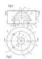
- Figures 1 and 2 show sections through an inventive Filter 1, here a dual-mode two-pole filter.
- Lines II-II in Figure 1 and I-I in Figure 2 indicate the sectional plane of each another figure.
- the filter 1 has a cylindrical metallic Shielding housing 2.
- a resonator 3 from Lanthanum aluminate is disposed inside the housing 2 and with its bottom 4 by a foot 5 connected, which together with the resonator 3 is formed in one piece.
- the resonator body 3 has the shape of a truncated cone with a large base 6, a small one Base 7 and a cross-section of the Figure 1 extending in a straight line, kegelmanteiförmigen Side surface 8.
- the proportions of the surfaces 6,7,8 are chosen so that the of the resonator body 3 modes supported those of a hemispherical Body are similar; the diameter of the small base 7 and the height of the resonator body 3 are each in the range of 0.4 to 0.6 times the diameter of the large footprint 6. This can be for example for a working frequency of the filter in the range of 23 to 25 mm.
- An input 9 and an output 10 for a microwave signal extend through the bottom 4 of the housing 2. They have the form of coaxial cables with an inner conductor 11, which penetrates the housing 2 and in the housing interior at a small distance from the large base 6 of the resonator body ends.
- the resonator body 3 has a rotation axis of symmetry 12. About the entrance 9 is in the resonator body 3 a field with an electric field vector 13 induced along the compound between the input 9 and the symmetry axis 12 oriented, as in particular in the plan view to recognize the resonator body 3 in Figure 2.
- a through the bottom 4 into the housing interior intervening Screw 14 represents a mode coupler, the one with the proportion of over the entrance 9 excited Mode interacts, located outside the resonator body and so the symmetry of the Filters 1 disturbs and a transition from microwave energy in an orthogonal to the excited mode Mode with field vector 15 causes. microwave energy from this mode is via the output 10 of the filter decoupled.
- Figure 3 shows a perspective view of a variant a resonator body for a dielectric Filter.
- This resonator body 3 has the Shape of a truncated pyramid with square Base surfaces 6 ', 7' and four side surfaces 8 '.
- On Foot 5 ' is also in the form of a - smaller - Truncated pyramid formed.
- this resonator body has a rotation axis of symmetry 12, the axis is fourfold, so that the resonator body 3 'orthogonal sets of degenerate Modes supported.
- the bevel could also over the entire small footprint 7 ' extend.
- the number of side surfaces of the resonator body 3 ' can also be greater than 4. ever the larger the number of side surfaces, the larger is the similarity to that proposed in Figure 1 Variant.
- the Resonator body also in one piece of two or more consist of stacked cones or truncated pyramids, so that one of the bases along two or more straight lines connecting side surface results. This allows a better approximation of the Hemispherical shape.
- FIG. 5 illustrates the production of dielectric filters with exactly predetermined resonance frequency according to the invention.
- the blank as shown in Figure 5a) is ground from a dielectric material such as single crystal lanthanum aluminate.
- This blank has a relative permittivity ⁇ r a resonance frequency f 0 .
- a blank having the dimensions shown in FIG. 5 a) can also be produced.
- this blank it is sufficient to remove its small base area 7 slightly further than shown in FIG. 5 c) (see FIG. 5 d)).
- the chamfering of the base surface 7 described in connection with FIG. 3 may expediently be generated for the purpose of mode locking.
- the blank can therefore cost in large Quantity manufactured and put in stock. ever After request can be very flexible and quickly a filter with a desired resonance frequency getting produced.
- all filters for a multiplexer be made from a raw form.
- the delivery time of such a multiplexer can be substantial be reduced, since after announcement of the Frequency planner by the customer's dielectric Body for all channels quickly by grinding one Area can be provided.
Landscapes
- Control Of Motors That Do Not Use Commutators (AREA)
Description
- Figur 1
- zeigt ein erfindungsgemäßes dielektrisches Filter im axialen Schnitt;
- Figur 2
- zeigt das Filter im Schnitt entlang der Linie II-II aus Figur 1;
- Figur 3
- zeigt eine perspektivische Ansicht eines Resonatorkörpers gemäß einer zweiten Ausgestaltung der Erfindung;
- Figur 4
- zeigt Querschnitte von zur Unterdrückung von unerwünschten Moden bearbeiteten Resonatorkörpern; und
- Figur 5
- veranschaulicht die Abstimmung der dielektrischen Filter auf eine gegebene Resonanzfrequenz.
Claims (9)
- Dielektrisches Filter mit einem Eingang und einem Ausgang für ein Mikrowellensignal und einem durch das Mikrowellensignal zu elektromagnetischen Schwingungen anregbaren, rotationssymmetrischen dielektrischen Resonatorkörper, dadurch gekennzeichnet, daß der Resonatorkörper (3;3') zwei verschieden große Grundflächen (6,7;6',7') senkrecht zu der Rotations-Symmetrieachse (12) und die Grundfläche (6,7;6',7') entlang gerader Linien verbindende Seitenflächen (8;8') hat.
- Dielektrisches Filter nach Anspruch 1, dadurch gekennzeichnet, daß der Resonatorkörper (3) ein Kegelstumpf ist.
- Dielektrisches Filter nach Anspruch 1, dadurch gekennzeichnet, daß der Resonatorkörper (3') ein Pyramidenstumpf ist.
- Dielektrisches Filter nach einem der vorhergehenden Ansprüche, dadurch gekennzeichnet, daß der dielektrische Resonatorkörper (3,3') an einer Grundfläche (6,6') einen Fuß (5,5') für die Befestigung des Resonatorkörpers in einem Gehäuse (2) trägt.
- Dielektrisches Filter nach einem der vorhergehenden Ansprüche, dadurch gekennzeichnet, daß es ein Multiple-Mode-Filter ist.
- Dielektrisches Filter nach Anspruch 5, dadurch gekennzeichnet, daß es ein Dual-Mode-Filter ist und daß eine der Grundflächen (7) bezogen auf die andere (6) geringfügig abgeschrägt ist, um eine Modenkopplung zu erzielen.
- Dielektrisches Filter nach einem der vorhergehenden Ansprüche, dadurch gekennzeichnet, daß an dem Resonatorkörper (3) lokal dielektrisches Material auf- und/oder abgetragen ist, um unerwünschte Moden zu unterdrücken oder ihre Frequenz zu verschieben.
- Dielekrisches Filter nach Anspruch 7, dadurch gekennzeichnet, daß der Resonatorkörper (3) so vorgefertigt ist, daß er eine niedrigere als die vorgegebene Resonanzfrequenz aufweist, um durch Abtragen von Material an der Grundfläche (7) die Resonanzfrequenz des Resonatorkörpers (3) so einstellen zu können, bis sie mit der vorgegebenen Resonanzfrequenz übereinstimmt.
- Verfahren zur Einstellung der Modenkopplung in einem dielektrischen Resonatorkörper (3') eines dielektrischen Multiple-Modefilters, bei dem von zwei gegenüberliegenden Grundflächen (6',7') des Resonatorkörpers (3') eine (7') abgeschrägt wird.
Applications Claiming Priority (3)
| Application Number | Priority Date | Filing Date | Title |
|---|---|---|---|
| DE19921926 | 1999-05-12 | ||
| DE19921926A DE19921926A1 (de) | 1999-05-12 | 1999-05-12 | Dielektrisches Mikrowellenfilter |
| PCT/DE2000/001085 WO2000070706A1 (de) | 1999-05-12 | 2000-04-07 | Dielektrisches mikrowellenfilter |
Publications (2)
| Publication Number | Publication Date |
|---|---|
| EP1181740A1 EP1181740A1 (de) | 2002-02-27 |
| EP1181740B1 true EP1181740B1 (de) | 2003-03-12 |
Family
ID=7907852
Family Applications (1)
| Application Number | Title | Priority Date | Filing Date |
|---|---|---|---|
| EP00925070A Expired - Lifetime EP1181740B1 (de) | 1999-05-12 | 2000-04-07 | Dielektrisches mikrowellenfilter |
Country Status (5)
| Country | Link |
|---|---|
| US (1) | US6717490B1 (de) |
| EP (1) | EP1181740B1 (de) |
| CA (1) | CA2373501C (de) |
| DE (2) | DE19921926A1 (de) |
| WO (1) | WO2000070706A1 (de) |
Cited By (8)
| Publication number | Priority date | Publication date | Assignee | Title |
|---|---|---|---|---|
| EP1575118A1 (de) * | 2004-03-12 | 2005-09-14 | M/A-Com, Inc. | Verfahren und Vorrichtung zur Abstimmung von Schaltungen mit dielektrischen Resonatoren |
| US7088203B2 (en) | 2004-04-27 | 2006-08-08 | M/A-Com, Inc. | Slotted dielectric resonators and circuits with slotted dielectric resonators |
| US7352264B2 (en) | 2005-10-24 | 2008-04-01 | M/A-Com, Inc. | Electronically tunable dielectric resonator circuits |
| US7388457B2 (en) | 2005-01-20 | 2008-06-17 | M/A-Com, Inc. | Dielectric resonator with variable diameter through hole and filter with such dielectric resonators |
| US7456712B1 (en) | 2007-05-02 | 2008-11-25 | Cobham Defense Electronics Corporation | Cross coupling tuning apparatus for dielectric resonator circuit |
| US7583164B2 (en) | 2005-09-27 | 2009-09-01 | Kristi Dhimiter Pance | Dielectric resonators with axial gaps and circuits with such dielectric resonators |
| US7705694B2 (en) | 2006-01-12 | 2010-04-27 | Cobham Defense Electronic Systems Corporation | Rotatable elliptical dielectric resonators and circuits with such dielectric resonators |
| US7719391B2 (en) | 2006-06-21 | 2010-05-18 | Cobham Defense Electronic Systems Corporation | Dielectric resonator circuits |
Families Citing this family (7)
| Publication number | Priority date | Publication date | Assignee | Title |
|---|---|---|---|---|
| US7310031B2 (en) | 2002-09-17 | 2007-12-18 | M/A-Com, Inc. | Dielectric resonators and circuits made therefrom |
| US7057480B2 (en) * | 2002-09-17 | 2006-06-06 | M/A-Com, Inc. | Cross-coupled dielectric resonator circuit |
| US20040257176A1 (en) * | 2003-05-07 | 2004-12-23 | Pance Kristi Dhimiter | Mounting mechanism for high performance dielectric resonator circuits |
| WO2005045985A1 (en) * | 2003-10-08 | 2005-05-19 | M/A-Com, Inc. | Tunable filter with cross-coupled dielectric resonators |
| DE112004000131T5 (de) * | 2003-12-24 | 2005-10-27 | Murata Manufacturing Co., Ltd., Nagaokakyo | Dielektrischer Resonator und diesen verwendendes Kommunikationsgerät |
| EP2031693B1 (de) * | 2007-08-28 | 2014-04-30 | ACE Technology | Frequenzabstimmbarer Filter |
| EP3280000B1 (de) * | 2015-04-29 | 2021-06-02 | Huawei Technologies Co., Ltd. | Dielektrisches filter |
Family Cites Families (8)
| Publication number | Priority date | Publication date | Assignee | Title |
|---|---|---|---|---|
| GB2222315B (en) * | 1988-08-24 | 1993-04-07 | Murata Manufacturing Co | Dielectric resonator |
| RU1793501C (ru) * | 1989-01-26 | 1993-02-07 | Научно-исследовательский институт прикладных физических проблем им.А.Н.Севченко | Диэлектрический резонатор |
| JP2509162Y2 (ja) * | 1989-08-31 | 1996-08-28 | 日本特殊陶業株式会社 | 誘電体共振器装置 |
| JP3425704B2 (ja) * | 1993-11-30 | 2003-07-14 | 株式会社村田製作所 | 誘電体共振器及び誘電体共振器の共振周波数調整方法 |
| JP3309379B2 (ja) * | 1994-09-09 | 2002-07-29 | 宇部興産株式会社 | デュアルモード誘電体導波管型フィルタ及びその特性調整方法 |
| FR2734084B1 (fr) * | 1995-05-12 | 1997-06-13 | Alcatel Espace | Resonateur dielectrique pour filtre hyperfrequence, et filtre comportant un tel resonateur |
| US6002311A (en) * | 1997-10-23 | 1999-12-14 | Allgon Ab | Dielectric TM mode resonator for RF filters |
| JP3506076B2 (ja) * | 1999-11-24 | 2004-03-15 | 株式会社村田製作所 | 多重モード誘電体共振器装置、フィルタ、デュプレクサおよび通信装置 |
-
1999
- 1999-05-12 DE DE19921926A patent/DE19921926A1/de not_active Withdrawn
-
2000
- 2000-04-07 US US10/019,863 patent/US6717490B1/en not_active Expired - Lifetime
- 2000-04-07 DE DE50001449T patent/DE50001449D1/de not_active Expired - Fee Related
- 2000-04-07 EP EP00925070A patent/EP1181740B1/de not_active Expired - Lifetime
- 2000-04-07 WO PCT/DE2000/001085 patent/WO2000070706A1/de not_active Ceased
- 2000-04-07 CA CA002373501A patent/CA2373501C/en not_active Expired - Fee Related
Cited By (9)
| Publication number | Priority date | Publication date | Assignee | Title |
|---|---|---|---|---|
| EP1575118A1 (de) * | 2004-03-12 | 2005-09-14 | M/A-Com, Inc. | Verfahren und Vorrichtung zur Abstimmung von Schaltungen mit dielektrischen Resonatoren |
| US7352263B2 (en) | 2004-03-12 | 2008-04-01 | M/A-Com, Inc. | Method and mechanism for tuning dielectric resonator circuits |
| US7088203B2 (en) | 2004-04-27 | 2006-08-08 | M/A-Com, Inc. | Slotted dielectric resonators and circuits with slotted dielectric resonators |
| US7388457B2 (en) | 2005-01-20 | 2008-06-17 | M/A-Com, Inc. | Dielectric resonator with variable diameter through hole and filter with such dielectric resonators |
| US7583164B2 (en) | 2005-09-27 | 2009-09-01 | Kristi Dhimiter Pance | Dielectric resonators with axial gaps and circuits with such dielectric resonators |
| US7352264B2 (en) | 2005-10-24 | 2008-04-01 | M/A-Com, Inc. | Electronically tunable dielectric resonator circuits |
| US7705694B2 (en) | 2006-01-12 | 2010-04-27 | Cobham Defense Electronic Systems Corporation | Rotatable elliptical dielectric resonators and circuits with such dielectric resonators |
| US7719391B2 (en) | 2006-06-21 | 2010-05-18 | Cobham Defense Electronic Systems Corporation | Dielectric resonator circuits |
| US7456712B1 (en) | 2007-05-02 | 2008-11-25 | Cobham Defense Electronics Corporation | Cross coupling tuning apparatus for dielectric resonator circuit |
Also Published As
| Publication number | Publication date |
|---|---|
| DE19921926A1 (de) | 2000-11-16 |
| US6717490B1 (en) | 2004-04-06 |
| EP1181740A1 (de) | 2002-02-27 |
| CA2373501A1 (en) | 2000-11-23 |
| DE50001449D1 (de) | 2003-04-17 |
| WO2000070706A1 (de) | 2000-11-23 |
| CA2373501C (en) | 2005-11-22 |
Similar Documents
| Publication | Publication Date | Title |
|---|---|---|
| DE3877235T2 (de) | Filter mit elementen mit verteilten parametern, wobei zwei arten von kopplungsvorrichtungen vorhanden sind. | |
| DE69317235T2 (de) | Wenig Raum beanspruchende, breitbandige Antenne mit zugehörigem Sendeempfänger | |
| EP1181740A1 (de) | Dielektrisches mikrowellenfilter | |
| DE69431412T2 (de) | Dielektrischer Resonator, dielektrisches Bandsperrfilter und dielektrisches Filter | |
| DE2538614C3 (de) | Dielektrischer Resonator | |
| DE68920496T2 (de) | Mit Dielektrikum belasteter Hohlraumresonator. | |
| EP0768725A2 (de) | Dielektrischer Resonator sowie Verwendung | |
| DE2510854A1 (de) | Bandpassfilter fuer mikrowellen | |
| WO2008009326A1 (de) | Hochfrequenzfilter in koaxialer bauweise | |
| DE10025262A1 (de) | Antennenvorrichtung | |
| DE3888456T2 (de) | Dielektrischer Resonator. | |
| DE69630163T2 (de) | Dielektrischer Resonator für Mikrowellenfilter und Filter damit | |
| EP1721359B1 (de) | Hochfrequenzfilter | |
| DE60036701T2 (de) | Temperaturkompensierter stabresonator | |
| EP0973227B1 (de) | Dual-Mode Ringresonator | |
| DE69418579T2 (de) | Dielektrischer koaxialer Resonator | |
| DE68911333T2 (de) | Filter mit einem dielektrischen Resonator. | |
| DE68917373T2 (de) | Magnetisch abstimmbares Bandpassfilter. | |
| DE60103406T2 (de) | Mit dielektrikum belasteter hohlraumresonator für hochfrequenzfilter | |
| DE69615961T2 (de) | Hermetisch abgedichtete Struktur zum Verbinden von zwei Wellenleitern | |
| DE69420368T2 (de) | Bikonischer Mehrmodenresonator | |
| EP1603187B1 (de) | Hohlraumresonator, Verwendung eines Hohlraumresonators und Oszillatorschaltung | |
| EP0883202A2 (de) | Vorrichtung zur Filterung von Hochfrequenzsignalen | |
| DE102015012401B4 (de) | Polarisations-bewahrendes Filter für einen dual polarisierten Hohlleiter | |
| DE69425235T2 (de) | Dielektrischer Resonator und Herstellunsverfahren dafür |
Legal Events
| Date | Code | Title | Description |
|---|---|---|---|
| PUAI | Public reference made under article 153(3) epc to a published international application that has entered the european phase |
Free format text: ORIGINAL CODE: 0009012 |
|
| 17P | Request for examination filed |
Effective date: 20011212 |
|
| AK | Designated contracting states |
Kind code of ref document: A1 Designated state(s): AT BE CH CY DE DK ES FI FR GB GR IE IT LI LU MC NL PT SE |
|
| GRAH | Despatch of communication of intention to grant a patent |
Free format text: ORIGINAL CODE: EPIDOS IGRA |
|
| RAP1 | Party data changed (applicant data changed or rights of an application transferred) |
Owner name: TESAT-SPACECOM GMBH & CO. KG |
|
| GRAH | Despatch of communication of intention to grant a patent |
Free format text: ORIGINAL CODE: EPIDOS IGRA |
|
| GRAA | (expected) grant |
Free format text: ORIGINAL CODE: 0009210 |
|
| AK | Designated contracting states |
Designated state(s): DE FR SE |
|
| REG | Reference to a national code |
Ref country code: IE Ref legal event code: FG4D Free format text: GERMAN |
|
| REF | Corresponds to: |
Ref document number: 50001449 Country of ref document: DE Date of ref document: 20030417 Kind code of ref document: P |
|
| PG25 | Lapsed in a contracting state [announced via postgrant information from national office to epo] |
Ref country code: SE Free format text: LAPSE BECAUSE OF FAILURE TO SUBMIT A TRANSLATION OF THE DESCRIPTION OR TO PAY THE FEE WITHIN THE PRESCRIBED TIME-LIMIT Effective date: 20030612 |
|
| REG | Reference to a national code |
Ref country code: IE Ref legal event code: FD4D Ref document number: 1181740E Country of ref document: IE |
|
| PG25 | Lapsed in a contracting state [announced via postgrant information from national office to epo] |
Ref country code: DE Free format text: LAPSE BECAUSE OF NON-PAYMENT OF DUE FEES Effective date: 20031101 |
|
| ET | Fr: translation filed | ||
| PLBE | No opposition filed within time limit |
Free format text: ORIGINAL CODE: 0009261 |
|
| STAA | Information on the status of an ep patent application or granted ep patent |
Free format text: STATUS: NO OPPOSITION FILED WITHIN TIME LIMIT |
|
| 26N | No opposition filed |
Effective date: 20031215 |
|
| PGFP | Annual fee paid to national office [announced via postgrant information from national office to epo] |
Ref country code: FR Payment date: 20040421 Year of fee payment: 5 |
|
| PG25 | Lapsed in a contracting state [announced via postgrant information from national office to epo] |
Ref country code: FR Free format text: LAPSE BECAUSE OF NON-PAYMENT OF DUE FEES Effective date: 20051230 |
|
| REG | Reference to a national code |
Ref country code: FR Ref legal event code: ST Effective date: 20051230 |