EP1179747A1 - Optische Anordnung zum Ablenkenn eines Lichtstrahls - Google Patents
Optische Anordnung zum Ablenkenn eines Lichtstrahls Download PDFInfo
- Publication number
- EP1179747A1 EP1179747A1 EP01116383A EP01116383A EP1179747A1 EP 1179747 A1 EP1179747 A1 EP 1179747A1 EP 01116383 A EP01116383 A EP 01116383A EP 01116383 A EP01116383 A EP 01116383A EP 1179747 A1 EP1179747 A1 EP 1179747A1
- Authority
- EP
- European Patent Office
- Prior art keywords
- mirror
- axis
- mirrors
- light beam
- arrangement according
- Prior art date
- Legal status (The legal status is an assumption and is not a legal conclusion. Google has not performed a legal analysis and makes no representation as to the accuracy of the status listed.)
- Granted
Links
- 230000003287 optical effect Effects 0.000 title claims abstract description 45
- 238000004519 manufacturing process Methods 0.000 description 3
- 238000005096 rolling process Methods 0.000 description 3
- 238000004140 cleaning Methods 0.000 description 1
- 238000011109 contamination Methods 0.000 description 1
- 230000003247 decreasing effect Effects 0.000 description 1
- 239000000428 dust Substances 0.000 description 1
- 230000037431 insertion Effects 0.000 description 1
- 238000003780 insertion Methods 0.000 description 1
- 238000003754 machining Methods 0.000 description 1
- 239000000463 material Substances 0.000 description 1
- 239000002245 particle Substances 0.000 description 1
- 238000005070 sampling Methods 0.000 description 1
- 238000004621 scanning probe microscopy Methods 0.000 description 1
- 238000007493 shaping process Methods 0.000 description 1
Images


Classifications
-
- G—PHYSICS
- G02—OPTICS
- G02B—OPTICAL ELEMENTS, SYSTEMS OR APPARATUS
- G02B21/00—Microscopes
- G02B21/0004—Microscopes specially adapted for specific applications
- G02B21/002—Scanning microscopes
- G02B21/0024—Confocal scanning microscopes (CSOMs) or confocal "macroscopes"; Accessories which are not restricted to use with CSOMs, e.g. sample holders
- G02B21/0036—Scanning details, e.g. scanning stages
- G02B21/0048—Scanning details, e.g. scanning stages scanning mirrors, e.g. rotating or galvanomirrors, MEMS mirrors
Definitions
- the present invention relates to an optical arrangement for deflection of a light beam in particular in two substantially perpendicular to each other lying directions, with two by means of a rotary drive each axes perpendicular to each other - x-axis and y-axis - rotatable first and third mirrors, one of the two mirrors being a second Mirror is assigned non-rotatably in a predetermined angular position so that the mutually assigned first and second mirrors together around the y-axis rotate while rotating the light beam around a pivot point that is on the axis of rotation - x-axis - of the third mirror.
- An optical arrangement of the generic type is from DE 196 54 210 C2 known.
- the arrangement for scanning known from this document of a beam advantageously enables high scan rates when deflecting of the light beam.
- a disadvantage of the known arrangement are scan errors that occur especially after scanning an object with a confocal Scanning microscope in the form of a hyperbolic distortion results.
- the Warping can be corrected arithmetically, but that is under Under certain circumstances problematic, especially when scanning an object that the sampling theorem is not fulfilled, the image is not clearly mathematical can be reconstructed.
- the present invention is therefore based on the object generic arrangement for deflecting a light beam in two im to indicate essentially perpendicular directions in this way and further develop that generated by the arrangement Distortion errors can be minimized and ideally eliminated.
- the arrangement of the first two mirrors according to the invention relative to the third mirror enables such a decoupling, since the optical axis of the reflected from the second mirror and to the third mirror running light beam always strikes the third mirror and the Impact point of the optical axis of the light beam on the axis of rotation of the third mirror - x-axis - and in the manner according to the invention during the rotation of the two mutually associated mirrors always in the perpendicular plane to the Y axis.
- the mirrors are arranged such that the optical axis of from the second mirror to the third mirror running light beam always essentially at one point on the Mirror surface of the third mirror hits, which is the intersection of the two Axes of rotation.
- This arrangement of the mirrors is when the the first two mirrors, regardless of their swivel angle, the optical Axis of the light beam reflected by the second mirror always around the pivoted the same point, which is advantageously a telecentric Beam path maintained even after the mirror arrangement.
- the third mirror is the one reflected or deflected by the third mirror.
- the light beam is always pivoted around the point on the mirror surface of the third mirror and is the intersection of the two axes of rotation. Consequently the light beam deflected by the three mirrors is particularly in two in deflected substantially perpendicular directions.
- the optical axis is at first Mirror incident light beam and the optical axis of that of the third Mirror of reflected light beam is essentially colinear.
- the third mirror is in the undeflected position located, i.e. the rotary drive rotating the third mirror is located in his rest position.
- the colinear arrangement of the optical axes is Particularly advantageous when adjusting or assembling the arrangement, because the incident light beam without the three mirrors of the deflection arrangement on the the same point that arises when the three mirrors of the Deflection arrangement are introduced into the optical beam path.
- the axis of rotation of the first two mirrors in essentially colinear to the optical axis of the first mirror incident light beam.
- the first two mirrors rotate around the y-axis the point of incidence of the optical axis of the incident Beam on the first mirror regardless of the angular position of the two first mirror always the same.
- the prerequisite for this is that the first mirror is arranged such that the axis of rotation of the two Mirror - the y-axis - and the mirror surface of the first mirror one Have intersection.
- the axis of rotation of the first two mirrors substantially colinear with the optical axis of that of the third Mirror of reflected light beam. This also only applies if the third mirror is not in the deflected position.
- the two first mirror rotating around the y-axis spatially between the first and the third mirror is arranged.
- This can also in advantageously a colinearity between the optical axis of the the first mirror incident light beam and the optical axis of the the third mirror of reflected light beam.
- the optical Arrangement for deflecting the light beam could be used without further deflection deflect or swivel a light beam running in one direction, the fulcrum of the deflected light beam on the optical axis of the originally running light beam.
- the distraction that can be achieved in this way would still have a central axis that aligns with the direction of the original running light beam coincides, so to speak, an "straight out” Distraction or fanning out.
- the first two Mirror rotating around the y-axis and the first mirror fourth mirror arranged.
- This mirror allows a distraction of the Light beam through almost any angle, so that through the optical Arrangement of deflected or fanned out light beam a central axis has that with the original direction of propagation of the light beam the reflection at the fourth mirror does not match.
- the fourth mirror is arranged stationary. If necessary, it is closed Adjustment purposes or adjustable during production, however after adjustment it is locked in position.
- the first two mirrors are arranged in a housing.
- the housing has at least two openings through which the light rays come in or can exit.
- the housing has corresponding receiving means to which the two mirrors are glued or attached in some other way can be.
- the housing is preferably made of light material and ideally shows through after its shaping production - for example Machining - Adequate accuracy so that after insertion of the two mirrors no further adjustment of the mirrors relative to that Housing is necessary. This advantageously makes it reproducible and enables fast production. It enters through one opening light striking the first mirror into the housing. Through the other The light reflected from the second mirror emerges from the opening out. Additional openings in the housing are for reasons of avoidance Contamination by dust particles is not provided.
- the housing however, could have a removable side wall that can be used for cleaning purposes, can be opened even after a long period of operation.
- the housing is connected directly to the rotary drive, preferably directly on its mechanical axis of rotation.
- it would be an indirect one Connection of the housing to the rotary drive is conceivable, for example via a gear, Cardan joint or a rolling leaf element.
- On rolling sheet element as is usually the case with magnetic heads from Computer hard drives are used - the case could be around an axis turn, which does not have to be colinear with the axis of rotation of the rotary drive.
- the third mirror could either directly or indirectly be connected to another rotary drive.
- the third is Mirror preferably directly on the mechanical axis of rotation further Rotary drive - which rotates about the x-axis - connected, in the latter case could the third mirror via a gear, universal joint or a rolling Leaf element to be connected to the further rotary drive.
- the two rotary drives can either directly or indirectly on one Recording device may be attached.
- the cradle could it is, for example, a plate to which the two rotary drives are attached are. This ensures that the two rotary drives in one well-defined position are arranged relative to each other.
- the cradle as an angle plate, a double angle plate or a housing can be formed with corresponding openings.
- the receiving device is advantageously rotatably arranged.
- the two Rotary drives of the three mirrors together around the axis of the receiving device rotated so that the orientation of the beam deflection directions is changeable.
- This is particularly advantageous because of this the orientation of the deflection direction of the third mirror rotating alone can be changed.
- the third mirror which rotates on its own, generally becomes operated at a much higher scanning speed than that two mirror-receiving housing, which is a much larger mass having. Accordingly, by rotating the cradle, the rapid direction of beam deflection of the third mirror, rotating by itself, as desired be oriented, which is particularly useful for confocal applications Scanning microscopy is of great advantage.
- the housing receiving the first two mirrors has a pivot bearing on.
- This pivot bearing could be stored in the receiving device. If no common receiving device is provided for the two rotary drives is, the pivot bearing could directly in the arrangement for deflection a housing receiving a light beam.
- the embodiment of the pivot bearing is colinear with the axis of rotation of the first two mirrors.
- the receiving device has at least one Has pivot bearing that a rotation of the receiving device by Axis allows.
- the pivot of the housing of the two mirrors could be mounted in a rotary bearing of the receiving device.
- the axis of the pivot of the housing of the two mirrors could be colinear be arranged to the axis of the rotary bearing of the receiving device.
- the individual Components are modular and easy to replace.
- the housing receiving the two mirrors and the housing rotating rotary drive combined to form an interchangeable module his.
- the third mirror and the rotary drive rotating it could an interchangeable module.
- the housing with the first two mirrors and its rotary drive be exchanged, for example, the angular range of the deflection about the y-axis to change.
- the third mirror and the rotary drive that rotates it could be exchanged as a module, for example a rotary drive use higher or lower scan rate in the optical arrangement.
- the field of application of the invention can be advantageously Arrangement can be expanded flexibly. Furthermore, the entire Receiving device in the form of an exchangeable module, so that the complete arrangement according to the invention for deflecting a Light beam is interchangeable.
- the interchangeable modules and / or the modular ones Receiving device has means for exact positioning. This means could, for example, in the form of guide elements and / or stop elements be executed.
- a rotary drive for the housing housing the first two mirrors or a galvanometer could be used for the third mirror.
- a resonant galvanometer could also achieve a high scan or deflection rate be used.
- a resonant galvanometer is preferred used as a rotary drive for the third mirror rotating alone.
- a stepper motor could also be used for the rotary drive.
- One of the following could also be used to achieve a high scan or deflection rate Mirror can be replaced by an active optical component.
- This could e.g. an AOD (Acousto-Optical-Deflector), EOD (Electro-Optical-Deflector) or a DMD (digital micro mirror device) can be used.
- AOD Acoustic-Optical-Deflector
- EOD Electro-Optical-Deflector
- DMD digital micro mirror device
- optical arrangement for deflecting a light beam i.e. the three mirrors, forward and / or at least one optically active component be subordinate.
- optically active component be an AOD, EOD or DMD.
- the optical arrangement has two by means of a rotary drive 4, 5 um axes perpendicular to each other - x-axis 6 and y-axis 7 - rotatable Mirror 8, 10, with the first mirror 8 having a further mirror 9 in a predetermined angular position is assigned non-rotatably, so that the each other associated mirrors 8, 9, i.e. first and second mirror, together around the turn y-axis 7 and thereby turn light beam 1 around a pivot point 11, which lies on the axis of rotation 6 - x axis - of the third mirror 10.
- the mirror 8, 9, 10 are arranged such that the optical Axis of the one running between the second and the third mirrors 9, 10 Light beam 12 always essentially in a x-axis 6, is perpendicular to the y-axis 7 plane.
- the mirrors 8, 9, 10 are arranged such that the optical axis of the second mirror 9 to the third mirror 10 extending light beam 12 always essentially at a point 11 on the mirror surface of the third mirror 10 strikes, which is the intersection of the two axes of rotation 6, 7. Accordingly, the deflected light beam 13 always pivots or rotates about the pivot point 11.
- the optical axis of the light beam 14 incident on the first mirror 8 and the optical axis of the light beam 13 reflected by the third mirror 10 is essentially colinear when the third mirror 10 is in the undeflected state Position, which is shown in Figs. 1 to 3, is located.
- the axis of rotation 7 of the first two mirrors 8, 9 is essentially colinear with the optical one Axis of the light beam 14 incident on the first mirror 8 the axis of rotation 7 of the first two mirrors 8, 9 is essentially colinear to the optical axis of the light beam reflected by the third mirror 10 13 when the third mirror 10 is in the undeflected position located.
- a fourth mirror 15 is arranged stationary.
- the first two Mirrors 8, 9 are arranged in a housing 16.
- the housing 16 has two openings 17, 18. Through the opening 17, the first Mirror 8 incident light beam 14 can pass through the opening 18 the light beam 12 reflected by the second mirror 9 to the third mirror 10 run.
- the housing 16 is connected directly to the rotary drive 5, specifically directly on its mechanical axis of rotation.
- the third mirror 10 is directly connected to that Rotary drive 4 connected to its mechanical axis of rotation.
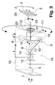
- the two rotary drives 4, 5 are directly on the receiving device shown in FIG. 3 19 attached.
- the receiving device 19 is rotatable arranged and rotates about the y-axis 7. By rotation of the receiving device 19 around the y-axis 7 it is possible to orient the beam deflection directions 2, 3 and thus to change the deflection pattern 20. Consequently can the fast beam deflection realized in this embodiment along direction 2 through the rotating mirror 10 in be advantageously oriented as desired.
- the axis of rotation 7 of the two first mirrors 8, 9 is essentially colinear to the optical axis of the light beam 14 incident on the first mirror 8. Furthermore, the axis of rotation 7 of the two first mirrors 8, 9 is essentially colinear to the optical axis of that reflected by the third mirror 10 Light beam 13 when the third mirror 10 is in the undeflected position located.
- a fourth mirror 15 is arranged stationary.
- the first two Mirrors 8, 9 are arranged in a housing 16.
- the housing 16 has two openings 17, 18. Through the opening 17, the first Mirror 8 incident light beam 14 can pass through the opening 18 the light beam 12 reflected by the second mirror 9 to the third mirror 10 run.
- Fig. 2 shows an embodiment according to the invention, in which the housing 16 accommodating the two first mirrors 8, 9 has a rotary bearing 21.
- the pivot bearing 21 has a passage 22 through which the deflected Light beam 13 can pass through.
- Fig. 2 can be seen that the pivot bearing 21 is mounted in the receiving device 19.
- the housing is thus 16 on the one hand by the rotary drive 5 and on the other hand by the rotary bearing 21 stored during the rotary movement about the y-axis 7.
- the pivot bearing 21 of the housing 16 of the two mirrors 8, 9 is in a pivot bearing 23 of the receiving device 19 stored.
- the pivot bearing 23 is not shown Housing that the inventive arrangement for deflecting a light beam absorbs, connected.
- the components of the optical arrangement for deflecting a light beam are shown in Modular, easily replaceable components. in this connection form the housing 16 and the two first mirrors 8, 9 the housing 16 rotating rotary drive 5, as shown in FIGS. 1 and 2 interchangeable module.
- the third mirror 10 and the rotary drive rotating it 4 form another interchangeable module.
- the total shown in Fig. 3 Receiving device 19 is also modular.
- the housing 16 rotating rotary drive 5 is designed as a galvanometer, the Can perform vibrations in a frequency range from 10 to 800 Hz.
- the rotary drive 4 rotating the third mirror 10 is a resonant galvanometer executed and vibrates at a frequency of 4 kHz.
- the Receiving device 19 is driven by a stepper motor, not shown rotated around the y-axis.
Landscapes
- Physics & Mathematics (AREA)
- Chemical & Material Sciences (AREA)
- Analytical Chemistry (AREA)
- General Physics & Mathematics (AREA)
- Optics & Photonics (AREA)
- Microscoopes, Condenser (AREA)
- Mechanical Light Control Or Optical Switches (AREA)
- Mechanical Optical Scanning Systems (AREA)
Abstract
Description
- Fig. 1
- eine schematische Darstellung eines ersten Ausführungsbeispiels einer erfindungsgemäßen optischen Anordnung zum Ablenken eines Lichtstrahls,
- Fig. 2
- eine schematische Darstellung eines zweiten erfindungsgemäßen Ausführungsbeispiels und
- Fig. 3
- eine schematische Darstellung eines dritten erfindungsgemäßen Ausführungsbeispiels.
Claims (16)
- Optische Anordnung zum Ablenken eines Lichtstrahls (1, 14) insbesondere in zwei im wesentlichen senkrecht zueinander liegenden Richtungen (2, 3), mit zwei mittels jeweils eines Drehantriebs (4, 5) um senkrecht zueinander liegende Achsen - x-Achse (6) und y-Achse (7) - drehbaren ersten und dritten Spiegel (8, 10), wobei einem der beiden Spiegel (8, 10) ein zweiter Spiegel (9) in einer vorgegebenen Winkelposition drehfest zugeordnet ist, so dass die einander zugeordneten ersten und zweiten Spiegel (8, 9) gemeinsam um die y-Achse (7) drehen und dabei den Lichtstrahl (1, 14) um einen Drehpunkt (11) drehen, der auf der Drehachse (6) - x-Achse - des dritten Spiegels (10) liegt,
dadurch gekennzeichnet, dass die Spiegel (8, 9, 10) derart angeordnet sind, dass die optische Achse des zwischen dem zweiten und dem dritten Spiegel (9, 10) verlaufenden Lichtstrahls (12) stets im wesentlichen in einer die x-Achse (6) umfassenden, senkrecht zur y-Achse (7) stehenden Ebene liegt. - Anordnung nach Anspruch 1, dadurch gekennzeichnet, dass die Spiegel (8, 9, 10) derart angeordnet sind, dass die optische Achse des von dem zweiten Spiegel (9) zu dem dritten Spiegel (10) verlaufenden Lichtstrahls stets im wesentlichen in einem Punkt (11) auf der Spiegelfläche des dritten Spiegels (10) auftrifft, der der Schnittpunkt der beiden Drehachsen (6, 7) ist.
- Anordnung nach Anspruch 1 oder 2, dadurch gekennzeichnet, dass die optische Achse des auf den ersten Spiegel (8) einfallenden Lichtstrahls (14) und die optische Achse des von dem dritten Spiegel (10) reflektierten Lichtstrahls (13) im wesentlichen kolinear ist, wenn sich der dritte Spiegel (10) unausgelenkt ist.
- Anordnung nach einem der Ansprüche 1 bis 3, dadurch gekennzeichnet, dass die Drehachse (7) der beiden ersten Spiegel (8, 9) im wesentlichen kolinear zu der optischen Achse des auf den ersten Spiegel (8) einfallenden Lichtstrahls (14) ist.
- Anordnung nach einem der Ansprüche 1 bis 4, dadurch gekennzeichnet, dass die Drehachse (7) des ersten und zweiten Spiegels (8, 9) im wesentlichen kolinear zu der optischen Achse des von dem dritten Spiegel (10) reflektierten Lichtstrahls (13) ist, wenn sich der dritte Spiegel (10) unausgelenkt ist.
- Anordnung nach einem der Ansprüche 1 bis 5, dadurch gekennzeichnet, dass zwischen dem den ersten und zweiten Spiegel (8, 9) um die y-Achse (7) drehenden Drehantrieb (5) und dem ersten Spiegel (8) ein vierter Spiegel (15) ortsfest angeordnet ist.
- Anordnung nach einem der Ansprüche 1 bis 6, dadurch gekennzeichnet, dass der erste und der zweite Spiegel (8, 9) in einem Gehäuse (16) angeordnet sind, dass das. Gehäuse (16) mindestens zwei Öffnungen (17, 18) aufweist, durch die Lichtstrahlen (14, 12) ein- bzw. austreten, und dass das Gehäuse (16) direkt mit dem Drehantrieb (5) verbunden ist.
- Anordnung nach einem der Ansprüche 1 bis 7, dadurch gekennzeichnet, dass der dritte Spiegel (10) direkt mit einem weiteren Drehantrieb (4) verbunden ist.
- Anordnung nach einem der Ansprüche 1 bis 8, dadurch gekennzeichnet, dass die beiden Drehantriebe (4, 5) unmittelbar an einer Aufnahmevorrichtung (19) angebracht sind und dass die Aufnahmevorrichtung (19) drehbar angeordnet ist..
- Anordnung nach Anspruch 9, dadurch gekennzeichnet, dass die Aufnahmevorrichtung (19) um die y-Achse (7) dreht, und dass durch Drehen der Aufnahmevorrichtung (19) die Orientierung der Strahlablenkrichtungen (2, 3) veränderbar ist..
- Anordnung nach einem der Ansprüche 7 bis 10, dadurch gekennzeichnet, dass das den ersten und zweiten Spiegel (8, 9) aufnehmende Gehäuse (16) ein Drehlager (21) aufweist, und dass das Drehlager (21) in der Aufnahmevorrichtung (19) gelagert ist.
- Anordnung nach Anspruch 21, dadurch gekennzeichnet, dass das Drehlager (21) des Gehäuses (16) der beiden Spiegel (8, 9) in einem Drehlager (23) der Aufnahmevorrichtung (19) gelagert ist.
- Anordnung nach einem der Ansprüche 7 bis 12, dadurch gekennzeichnet, dass das die beiden ersten Spiegel (8, 9) aufnehmende Gehäuse (16) und der das Gehäuse (16) drehende Drehantrieb (5) zu einem austauschbaren Modul zusammengefasst ist, dass der dritte Spiegel (10) und der ihn drehende Drehantrieb (4) zu einem austauschbaren Modul zusammengefasst ist und dass die Aufnahmevorrichtung (19) in Form eines austauschbaren Moduls ausgeführt ist.
- Anordnung nach einem der Anspruch 13, dadurch gekennzeichnet, dass die austauschbaren Module und/oder die modular ausgeführte Aufnahmevorrichtung (19) Führungselemente und/oder Anschlagelemente aufweisen.
- Anordnung nach einem der Ansprüche 1 bis 14, dadurch gekennzeichnet, dass als Drehantrieb (4, 5) ein Galvanometer oder ein Schrittmotor dient.
- Anordnung nach einem der Ansprüche 1 bis 15, dadurch gekennzeichnet, dass mindestens einer der Spiegel (8, 9, 10) durch ein optisch aktives Bauteil, beispielsweise ein AOD (Acousto-Optical-Deflector), EOD (Electro-Optical-Deflector) oder DMD (Digital Micro-Mirror-Device) ersetzbar ist.
Applications Claiming Priority (2)
| Application Number | Priority Date | Filing Date | Title |
|---|---|---|---|
| DE10033549 | 2000-07-11 | ||
| DE10033549A DE10033549A1 (de) | 2000-07-11 | 2000-07-11 | Optische Anordnung zum Ablenken eines Lichtstrahls insbesondere in zwei im wesentlichen senkrecht zueinander liegenden Richtungen |
Publications (2)
| Publication Number | Publication Date |
|---|---|
| EP1179747A1 true EP1179747A1 (de) | 2002-02-13 |
| EP1179747B1 EP1179747B1 (de) | 2006-02-15 |
Family
ID=7648467
Family Applications (1)
| Application Number | Title | Priority Date | Filing Date |
|---|---|---|---|
| EP01116383A Expired - Lifetime EP1179747B1 (de) | 2000-07-11 | 2001-07-06 | Optische Anordnung zum Ablenken eines Lichtstrahls |
Country Status (4)
| Country | Link |
|---|---|
| US (1) | US6618178B2 (de) |
| EP (1) | EP1179747B1 (de) |
| JP (1) | JP4467841B2 (de) |
| DE (2) | DE10033549A1 (de) |
Families Citing this family (25)
| Publication number | Priority date | Publication date | Assignee | Title |
|---|---|---|---|---|
| DE10039520A1 (de) | 2000-08-08 | 2002-02-21 | Leica Microsystems | Vorrichtung zur Untersuchung und Manipulation von mikroskopischen Objekten |
| DE10137154A1 (de) * | 2001-07-30 | 2003-02-20 | Leica Microsystems | Scanmikroskop und optisches Element |
| DE10209321A1 (de) * | 2002-03-02 | 2003-09-25 | Leica Microsystems | Vorrichtung zum Ablenken eines Lichtstrahles und Scanmikroskop |
| DE10209322A1 (de) * | 2002-03-02 | 2003-09-25 | Leica Microsystems | Vorrichtung zum Ablenken eines Lichtstrahles und Scanmikroskop |
| DE10231475A1 (de) | 2002-07-12 | 2004-01-22 | Leica Microsystems Heidelberg Gmbh | Scanmikroskop mit optischem Bauteil und optisches Bauteil |
| JP4642397B2 (ja) * | 2004-07-12 | 2011-03-02 | オリンパス株式会社 | 光走査型顕微鏡装置 |
| DE102004058263A1 (de) * | 2004-12-03 | 2006-06-08 | Rehau Ag + Co | Einrichtung zur Führung eines Strahles, insbesondere eines Laserstrahles, Vorrichtung zur optischen Bearbeitung, insbesondere zur Laserbearbeitung, und Verfahren zum Führen eines Strahles, insbesondere eines Laserstrahles |
| US7345800B2 (en) | 2005-02-04 | 2008-03-18 | Leica Microsystems Cms Gmbh | Optical arrangement for deflecting a light beam |
| US7576837B2 (en) * | 2006-08-29 | 2009-08-18 | The United States Of America As Represented By The Secretary Of The Army | Micro-mirror optical tracking and ranging system |
| US7918563B2 (en) * | 2007-08-01 | 2011-04-05 | Texas Instruments Incorporated | System and method for utilizing a scanning beam to display an image |
| US8400619B1 (en) * | 2008-08-22 | 2013-03-19 | Intelligent Automation, Inc. | Systems and methods for automatic target tracking and beam steering |
| WO2010069987A1 (de) * | 2008-12-19 | 2010-06-24 | Deutsches Krebsforschungszentrum | Verfahren und vorrichtung zur dynamischen verlagerung eines lichtstrahls gegenüber einer den lichtstrahl fokussierenden optik |
| JP5325640B2 (ja) * | 2009-04-08 | 2013-10-23 | オリンパス株式会社 | 内視鏡装置及びその光走査方法 |
| DE102010007727A1 (de) | 2010-02-12 | 2011-08-18 | Leica Microsystems CMS GmbH, 35578 | Vorrichtung nach Art eines Scan-Mikroskops, Vorrichtung in Form einer Baueinheit für ein Mikroskop und Verfahren und Vorrichtung zum optischen Abtasten einer oder mehrerer Proben |
| DE102010037786A1 (de) | 2010-09-27 | 2012-03-29 | Leica Microsystems Cms Gmbh | Verfahren zur Detektion von transmittiertem Licht im konfokalen Laserscan-Mikroskop und konfokales Laserscan-Mikroskop |
| JP5603749B2 (ja) * | 2010-11-18 | 2014-10-08 | オリンパス株式会社 | 顕微鏡装置 |
| DE102010061612B4 (de) * | 2010-12-29 | 2023-12-28 | Leica Microsystems Cms Gmbh | Verfahren zum Ermitteln von Scankoordinaten zum Betreiben einer Scaneinheit eines konfokalen Scan-Mikroskops und konfokales Scan-Mikroskop |
| DE102012101778A1 (de) * | 2012-03-02 | 2013-09-05 | Leica Microsystems Cms Gmbh | Scanmikroskopisches Verfahren und Scanmikroskop |
| US9200887B2 (en) | 2012-10-12 | 2015-12-01 | Thorlabs, Inc. | Compact, low dispersion, and low aberration adaptive optics scanning system |
| CN105980927B (zh) | 2013-12-10 | 2018-09-18 | 杜比实验室特许公司 | 用于投影系统的声光光束转向调制器 |
| TWI659227B (zh) | 2017-06-20 | 2019-05-11 | Academia Sinica | 以影像導引之顯微照射的顯微鏡系統及方法 |
| EP3588163B1 (de) * | 2018-06-21 | 2024-10-16 | Academia Sinica | Mikroskopbasiertes system und verfahren zur bildgeführten mikroskopbeleuchtung |
| DE102018118699A1 (de) * | 2018-08-01 | 2020-02-06 | Carl Zeiss Microscopy Gmbh | Scanneranordnung für optische Strahlung |
| JP7738302B2 (ja) * | 2020-07-28 | 2025-09-12 | カール ツァイス マイクロスコピー ゲーエムベーハー | 光子計数検出器要素の複数のアレイを有する光学顕微鏡とその方法 |
| DE102021122662A1 (de) | 2021-09-01 | 2023-03-02 | Scanlab Gmbh | Optikeinheit für eine Laserbearbeitungsvorrichtung |
Citations (3)
| Publication number | Priority date | Publication date | Assignee | Title |
|---|---|---|---|---|
| US4196461A (en) * | 1979-03-06 | 1980-04-01 | Chartglen, Ltd. | Pattern generating entertainment device |
| US4874215A (en) * | 1987-04-23 | 1989-10-17 | General Scanning, Inc. | Tunable resonant mechanical system |
| US5561544A (en) * | 1995-03-06 | 1996-10-01 | Macken; John A. | Laser scanning system with reflecting optics |
Family Cites Families (4)
| Publication number | Priority date | Publication date | Assignee | Title |
|---|---|---|---|---|
| US3718761A (en) * | 1968-03-27 | 1973-02-27 | Hughes Aircraft Co | Omnidirectional planar optical code reader |
| US4264152A (en) * | 1979-02-26 | 1981-04-28 | Sri International | Visual stimulus deflector |
| JPH0778574B2 (ja) * | 1986-06-05 | 1995-08-23 | オリンパス光学工業株式会社 | 実体顕微鏡用可変傾斜角双眼鏡筒 |
| DE19654210C2 (de) | 1996-12-24 | 1999-12-09 | Leica Microsystems | Optische Anordnung zum Scannen eines Strahls in zwei im wesentlichen senkrecht zueinander liegenden Achsen |
-
2000
- 2000-07-11 DE DE10033549A patent/DE10033549A1/de not_active Withdrawn
-
2001
- 2001-07-04 JP JP2001203644A patent/JP4467841B2/ja not_active Expired - Lifetime
- 2001-07-06 DE DE50108931T patent/DE50108931D1/de not_active Expired - Lifetime
- 2001-07-06 EP EP01116383A patent/EP1179747B1/de not_active Expired - Lifetime
- 2001-07-09 US US09/901,274 patent/US6618178B2/en not_active Expired - Lifetime
Patent Citations (3)
| Publication number | Priority date | Publication date | Assignee | Title |
|---|---|---|---|---|
| US4196461A (en) * | 1979-03-06 | 1980-04-01 | Chartglen, Ltd. | Pattern generating entertainment device |
| US4874215A (en) * | 1987-04-23 | 1989-10-17 | General Scanning, Inc. | Tunable resonant mechanical system |
| US5561544A (en) * | 1995-03-06 | 1996-10-01 | Macken; John A. | Laser scanning system with reflecting optics |
Also Published As
| Publication number | Publication date |
|---|---|
| US6618178B2 (en) | 2003-09-09 |
| EP1179747B1 (de) | 2006-02-15 |
| JP2002062504A (ja) | 2002-02-28 |
| DE50108931D1 (de) | 2006-04-20 |
| US20020008904A1 (en) | 2002-01-24 |
| JP4467841B2 (ja) | 2010-05-26 |
| DE10033549A1 (de) | 2002-01-24 |
Similar Documents
| Publication | Publication Date | Title |
|---|---|---|
| EP1179747B1 (de) | Optische Anordnung zum Ablenken eines Lichtstrahls | |
| EP0950208B1 (de) | Optische anordnung zum scannen eines strahls in zwei im wesentlichen senkrecht zueinander liegenden achsen | |
| EP0179275B1 (de) | Einrichtung zur Ablenkung eines Lichtstrahls | |
| DE19737172A1 (de) | Optisches Kaskade-Abtastsystem | |
| DE4140710A1 (de) | Positioniersystem | |
| DE20320269U1 (de) | Optisches System zur variablen Fokussierung eines Lichtstrahls | |
| DE102009054888A1 (de) | Optisches Element mit einer Mehrzahl von refletiven Facettenelementen | |
| DE102018221203A1 (de) | Laserbearbeitungsmaschine mit einem Wobbelscanner | |
| DE4001745C2 (de) | ||
| DE102012102566B4 (de) | Übertragungselement für eine Stellbewegung eines optischen Elementes, Positioniereinrichtung sowie Bearbeitungskopf für eine Laserbearbeitungsmaschine | |
| EP1485762A2 (de) | Vorrichtung zur manipulation der winkellage eines gegenstands gegen ber einer festen struktur | |
| DE69712470T2 (de) | Lasermarkierungs- oder laserperforierungssystem | |
| EP1113301B1 (de) | Vorrichtung zur Strahlablenkung | |
| DE19960807C1 (de) | Vorrichtung zum Ablenken eines Strahls | |
| WO1997015855A2 (de) | Optisches gerät | |
| DE102005040834A1 (de) | Einrichtung zum Wechseln von Objektiven an optischen Geräten, insbesondere an Mikroskopen | |
| DE102022107324A1 (de) | Auslenkvorrichtung für einen Laserbearbeitungskopf und Laserbearbeitungskopf mit derselben | |
| DE2752145C2 (de) | Vorrichtung zur Erzeugung einer Auflichtanzeige auf einer zu bestückenden Leiterplatte | |
| DE10130199B4 (de) | Scannervorrichtung für einen Leistungslaser | |
| EP1055948B1 (de) | Vorrichtung zur Feinpositionierung eines Bauteils | |
| DE102008041818B4 (de) | Optisches System zum Zusammenführen eines ersten und eines zweiten jeweils von einem Objekt ausgehenden Teilbildstrahls zu einem Ergebnisbildstrahl | |
| DE3820783C2 (de) | ||
| DE102018001570A1 (de) | Vorrichtung und Verfahren zum Bearbeiten eines Werkstücks mittels eines Laserstrahls | |
| EP0422151A1 (de) | Vorrichtung zur definierten farb- und richtungsbeeinflussung eines weisslicht-laserstrahls | |
| DE4215128C2 (de) | Spaltlampe mit veränderbarem Spaltlicht-Einstrahlwinkel |
Legal Events
| Date | Code | Title | Description |
|---|---|---|---|
| PUAI | Public reference made under article 153(3) epc to a published international application that has entered the european phase |
Free format text: ORIGINAL CODE: 0009012 |
|
| AK | Designated contracting states |
Kind code of ref document: A1 Designated state(s): CH DE FR GB LI NL Kind code of ref document: A1 Designated state(s): AT BE CH CY DE DK ES FI FR GB GR IE IT LI LU MC NL PT SE TR |
|
| AX | Request for extension of the european patent |
Free format text: AL;LT;LV;MK;RO;SI |
|
| 17P | Request for examination filed |
Effective date: 20020809 |
|
| AKX | Designation fees paid |
Free format text: CH DE FR GB LI NL |
|
| 17Q | First examination report despatched |
Effective date: 20041028 |
|
| GRAP | Despatch of communication of intention to grant a patent |
Free format text: ORIGINAL CODE: EPIDOSNIGR1 |
|
| RIN1 | Information on inventor provided before grant (corrected) |
Inventor name: ENGELHARDT, JOHANN, DR. |
|
| GRAS | Grant fee paid |
Free format text: ORIGINAL CODE: EPIDOSNIGR3 |
|
| GRAA | (expected) grant |
Free format text: ORIGINAL CODE: 0009210 |
|
| AK | Designated contracting states |
Kind code of ref document: B1 Designated state(s): CH DE FR GB LI NL |
|
| PG25 | Lapsed in a contracting state [announced via postgrant information from national office to epo] |
Ref country code: NL Free format text: LAPSE BECAUSE OF FAILURE TO SUBMIT A TRANSLATION OF THE DESCRIPTION OR TO PAY THE FEE WITHIN THE PRESCRIBED TIME-LIMIT Effective date: 20060215 |
|
| REG | Reference to a national code |
Ref country code: GB Ref legal event code: FG4D Free format text: NOT ENGLISH Ref country code: CH Ref legal event code: EP |
|
| GBT | Gb: translation of ep patent filed (gb section 77(6)(a)/1977) |
Effective date: 20060329 |
|
| REF | Corresponds to: |
Ref document number: 50108931 Country of ref document: DE Date of ref document: 20060420 Kind code of ref document: P |
|
| RAP2 | Party data changed (patent owner data changed or rights of a patent transferred) |
Owner name: LEICA MICROSYSTEMS CMS GMBH |
|
| NLT2 | Nl: modifications (of names), taken from the european patent patent bulletin |
Owner name: LEICA MICROSYSTEMS CMS GMBH Effective date: 20060517 |
|
| PG25 | Lapsed in a contracting state [announced via postgrant information from national office to epo] |
Ref country code: CH Free format text: LAPSE BECAUSE OF NON-PAYMENT OF DUE FEES Effective date: 20060731 Ref country code: LI Free format text: LAPSE BECAUSE OF NON-PAYMENT OF DUE FEES Effective date: 20060731 |
|
| NLV1 | Nl: lapsed or annulled due to failure to fulfill the requirements of art. 29p and 29m of the patents act | ||
| PLBE | No opposition filed within time limit |
Free format text: ORIGINAL CODE: 0009261 |
|
| STAA | Information on the status of an ep patent application or granted ep patent |
Free format text: STATUS: NO OPPOSITION FILED WITHIN TIME LIMIT |
|
| 26N | No opposition filed |
Effective date: 20061116 |
|
| REG | Reference to a national code |
Ref country code: CH Ref legal event code: PL |
|
| EN | Fr: translation not filed | ||
| PG25 | Lapsed in a contracting state [announced via postgrant information from national office to epo] |
Ref country code: FR Free format text: LAPSE BECAUSE OF FAILURE TO SUBMIT A TRANSLATION OF THE DESCRIPTION OR TO PAY THE FEE WITHIN THE PRESCRIBED TIME-LIMIT Effective date: 20070105 |
|
| PG25 | Lapsed in a contracting state [announced via postgrant information from national office to epo] |
Ref country code: FR Free format text: LAPSE BECAUSE OF FAILURE TO SUBMIT A TRANSLATION OF THE DESCRIPTION OR TO PAY THE FEE WITHIN THE PRESCRIBED TIME-LIMIT Effective date: 20060215 |
|
| PGFP | Annual fee paid to national office [announced via postgrant information from national office to epo] |
Ref country code: GB Payment date: 20200724 Year of fee payment: 20 Ref country code: DE Payment date: 20200928 Year of fee payment: 20 |
|
| REG | Reference to a national code |
Ref country code: DE Ref legal event code: R071 Ref document number: 50108931 Country of ref document: DE |
|
| REG | Reference to a national code |
Ref country code: GB Ref legal event code: PE20 Expiry date: 20210705 |
|
| PG25 | Lapsed in a contracting state [announced via postgrant information from national office to epo] |
Ref country code: GB Free format text: LAPSE BECAUSE OF EXPIRATION OF PROTECTION Effective date: 20210705 |