EP1179689A1 - Courroie pour transmission continûment variable - Google Patents
Courroie pour transmission continûment variable Download PDFInfo
- Publication number
- EP1179689A1 EP1179689A1 EP01119002A EP01119002A EP1179689A1 EP 1179689 A1 EP1179689 A1 EP 1179689A1 EP 01119002 A EP01119002 A EP 01119002A EP 01119002 A EP01119002 A EP 01119002A EP 1179689 A1 EP1179689 A1 EP 1179689A1
- Authority
- EP
- European Patent Office
- Prior art keywords
- metal
- ring assembly
- belt
- metal ring
- radially
- Prior art date
- Legal status (The legal status is an assumption and is not a legal conclusion. Google has not performed a legal analysis and makes no representation as to the accuracy of the status listed.)
- Granted
Links
Images


Classifications
-
- F—MECHANICAL ENGINEERING; LIGHTING; HEATING; WEAPONS; BLASTING
- F16—ENGINEERING ELEMENTS AND UNITS; GENERAL MEASURES FOR PRODUCING AND MAINTAINING EFFECTIVE FUNCTIONING OF MACHINES OR INSTALLATIONS; THERMAL INSULATION IN GENERAL
- F16G—BELTS, CABLES, OR ROPES, PREDOMINANTLY USED FOR DRIVING PURPOSES; CHAINS; FITTINGS PREDOMINANTLY USED THEREFOR
- F16G5/00—V-belts, i.e. belts of tapered cross-section
- F16G5/16—V-belts, i.e. belts of tapered cross-section consisting of several parts
Definitions
- the present invention relates to a belt for a continuously variable transmission, which is wound around a drive pulley and a driven pulley for transmitting a driving force between both the pulleys, and which comprises a metal ring assembly formed of a plurality of endless metal rings laminated one on another, and a large number of metal elements each having a ring slot into which the metal ring assembly is fitted.
- the metal elements 32 are supported on the metal ring assemblies 31, 31 which are fitted into the ring slots 35, 35. If the metal elements 32 are inclined forwards in a travel direction, rear ends a of saddle faces 38L, 38L in the travel direction abut against inner peripheral surfaces of the metal ring assemblies 31, 31, and front ends b of the lower faces 38U, 38U of an ear abut against the outer peripheral surfaces of the metal ring assemblies 31, 31. For this reason, there is a possibility that a large stress ⁇ H (Hertz's stress) is generated at such abutment portions and as a result, the metal ring assemblies 31, 31 are worn.
- ⁇ H Hertz's stress
- the forward inclination of the metal elements 32 in the travel direction is caused by a tangent frictional force F received by the metal elements 32 at their contact faces with the pulleys, and an urging force between the metal elements 32, and is particularly significant at an exit portion of the driven pulley. The reason will be described below.
- a moment generated in a direction of an arrow M by the tangent frictional force F acts to incline the metal elements 32 forwards in the travel direction about a swinging center C.
- a radial frictional force ⁇ E generated by the urging force E between the metal elements 32 generates a moment in a direction of an arrow M' on the metal elements 32. This moment acts to incline the metal elements 32 rearwards in the travel direction about the swinging center C.
- the tangent frictional force F received by the metal elements 32 from the pulleys 6 and 11 is large at the exit portions of the drive pulley 6 and the driven pulley 11 as shown in Fig.9A, and its value reaches four times a value provided when it is supposed that the tangent frictional force F has been averagely distributed over the entire wound regions of the pulleys 6 and 11.
- the urging force between the metal elements 32 has a larger value at the exit portion of the drive pulley 6, but assumes 0 (zero) at the exit portion of the driven pulley 11.
- the metal elements 32 are liable to be inclined forwards in the travel direction to the largest extent at a location where the tangent frictional force F inclining the metal element 32 forwards in the travel direction is largest and the urging force E inhibiting the forward inclination of the metal element 32 in the travel direction is 0 (zero), i.e., at the exit portion of the driven pulley 11 (see Fig.10).
- the longitudinal shapes of the saddle face of the metal element are formed asymmetrically in such a manner that the rear portion of the saddle face in the travel direction is lower in height level than the front portion in the travel direction, for the purpose of preventing the inclination of the metal element in the longitudinal direction by a pitching moment.
- These belts suffer from a problem of an increase in processing cost for the metal element, because the shape of the saddle face is complicated.
- the belts described in the above Japanese Patent Publication Nos. 2-19338 and 7-12177, and Japanese Patent Publication No. 2,617,784 are for suppressing a rolling of the metal elements, and cannot solve the problem of wear in the metal ring assemblies due to a pitching of the metal elements.
- the present invention has been accomplished with the above circumstance in view, and it is an object of the present invention to prevent the wear of the metal ring assembly due to the inclination of the metal element without increasing of the processing cost for the metal element.
- a belt for a continuously variable transmission which is wound around a drive pulley and a driven pulley for transmitting a driving force between both the pulleys
- the belt comprising a metal ring assembly formed of a plurality of endless metal rings laminated one on another, and a large number of metal elements each having a ring slot into which the metal ring assembly is fitted, wherein an endless resilient member which is deformable radially is disposed between a radially outer edge of the ring slot in the metal element and a radially outer peripheral surface of the metal ring assembly.
- the endless resilient member which is deformable radially is disposed between the radially outer edge of the ring slot in the metal element and the radially outer peripheral surface of the metal ring assembly. Therefore, when the metal elements are inclined in such a manner that they are fallen forwards in the vicinity of an exit portion of the driven pulley of the metal belt type continuously variable transmission, the metal ring assembly can be prevented from strongly interfering with the radially outer and inner edges of the ring slot in the metal ring assembly by a buffering action provided when the resilient member is deformed radially, thereby preventing wear of the metal belt to enhance the durability thereof.
- the belt is of a simple structure in which the resilient member is only added without subjecting the metal element to a special processing, and hence, the belt can be realized at an extremely low cost.
- the peripheral length of the radially inner peripheral surface of the resilient member is set longer than that of the radially outer peripheral surface of the metal ring assembly.
- the peripheral length of the radially inner peripheral surface of the resilient member is longer than that of the radially outer peripheral surface of the metal ring assembly, and hence, a clearance can be created between the resilient member and the metal ring assembly, to thereby further increase the buffering action of the resilient member.
- Figs.1 to 7 shows a first embodiment of the present invention.
- Fig.1 schematically shows the structure of a metal belt type continuously variable transmission T mounted on an automobile.
- An input shaft 3 connected to a crankshaft 1 of an engine E through a damper 2 is connected to a driving shaft 5 of the metal belt type continuously variable transmission T through a starting clutch 4.
- a drive pulley 6 provided on the driving shaft 5 comprises a stationary pulley half 7 secured to the driving shaft 5, and a movable pulley half 8 capable of moving toward and away from the stationary pulley half 7.
- the movable pulley half 8 is forced toward the stationary pulley half 7 by a hydraulic pressure applied to an oil chamber 9.
- a driven pulley 11 is provided on a driven shaft 10 disposed in parallel to the driving shaft 5, and comprises a stationary pulley half 12 secured to the driven shaft 10, and a movable pulley half 13 capable of moving toward and away from the stationary pulley half 12.
- the movable pulley half 13 is forced toward the stationary pulley half 12 by a hydraulic pressure applied to an oil chamber 14.
- a metal belt 15 is wound around the drive pulley 6 and the driven pulley 11, and comprises a large number of metal elements 32 supported on a pair of left and right metal ring assemblies 31, 31 (see Fig.2).
- Each of the metal ring assemblies 31, 31 comprises, for example, 12 metal rings 33 which are laminated on one another.
- a forward drive gear 16 and a backward drive gear 17 are relatively rotatably supported on the driven shaft 10.
- the forward drive gear 16 and the backward drive gear 17 can be coupled selectively to the driven shaft 10 by a selector 18.
- a forward driven gear 20 meshed with the forward drive gear 16 and a backward driven gear 22 meshed with the backward drive gear 17 through a backward idling gear 21 are secured to an output shaft 19 which is disposed in parallel to the driven shaft 10.
- the rotation of the output shaft 19 is input to a differential 25 through a final drive gear 23 and a final driven gear 24, and is transmitted therefrom through left and right axles 26, 26 to driven wheels W, W.
- a driving force of the engine E is transmitted to the driven shaft 10 through the crankshaft 1, the damper 2, the input shaft 3, the start clutch 4, the drive shaft 5, the driven pulley 6, the metal belt 15 and the driven pulley 11.
- the driving force of the driven shaft 10 is transmitted to the output shaft 19 through the forward drive gear 16 and the forward driven gear 20, thereby allowing the vehicle to travel forwards.
- the driving force of the driven shaft 10 is transmitted to the output shaft 19 through the backward drive gear 17, the backward idling gear 21 and the backward driven gear 22, thereby allowing the vehicle to travel backwards.
- this metal belt type continuously variable transmission T hydraulic pressures applied to the oil chamber 9 of the drive pulley 6 and the oil chamber 14 of the driven pulley 11 are controlled by a hydraulic pressure control unit U2 which is operated by a command from an electronic control unit U1, thereby continuously adjusting the change gear ratio. Specifically, if a hydraulic pressure applied to the oil chamber 14 of the driven pulley 11 is increased relative to a hydraulic pressure applied to the oil chamber 9 of the drive pulley 6, the grove width of the driven pulley 11 is reduced, leading to an increased effective radius, and correspondingly, the groove width of the drive pulley 6 is increased, leading to a reduced effective radius. Therefore, the change gear ratio of the metal belt type continuous variable transmission T is continuously varied toward "LOW".
- each of the metal elements 32 formed from a metal plate by punching includes a substantially trapezoidal element body 34, a neck 36 located between a pair of left and right ring slots 35, 35 into which the metal ring assemblies 31, 31 are fitted, and a substantially triangular ear 37 connected to an upper portion of the element body 34 through the neck 36.
- the metal ring assemblies 31, 31 are sandwiched between saddle faces 38L, 38L constituting radially inner edges of the ring slots 35, 35 and lower faces 38U, 38U of the ear constituting radially outer edges of the ring slots 35, 35.
- the innermost metal rings 33, 33 of the metal ring assemblies 31, 31 are supported on the saddle faces 38L, 38L, and clearances are defined between the outermost metal rings 33, 33 of the metal ring assemblies 31, 31 and the lower faces 38U, 38U of the ear.
- Retainers 44, 44 formed into an endless band-shape from an resilient material are disposed in the clearances.
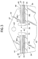
- the peripheral length of an inner surface of each of the retainers 44, 44 is set larger than that of an outer surface of each of the outermost metal rings 33, 33 and hence, a clearance ⁇ is defined between each of the retainers 44 and each of the outermost metal rings 33, 33 (see Fig.3).
- a clearance ⁇ is also defined between each of the retainers 44, 44 and each of the lower faces 38U, 38U of the ear (see Fig.3).
- the clearance ⁇ is set at 0.10 mm, and the clearance ⁇ is set at 0.05 mm. Setting the clearance ⁇ smaller than the clearance ⁇ ensures that the clearances can be defined between the outermost metal rings 33, 33 and the retainers 44, 44 over the entire peripheries of the metal belt assemblies, thereby providing a buffering effect.
- Each of the metal ring assemblies 31, 31 comprises a laminate of eleven metal rings 33, and each of the retainers 44, 44 comprises two metal rings 45, 45 longer than the peripheral length of the outer surface of the outermost metal ring 33.
- the retainer 44 constitutes a resilient member of the present invention.
- a pair of pulley-abutment faces 39, 39 are formed at laterally opposite ends of the element body 34 and capable of abutting against V-faces of the drive pulley 6 and the driven pulley 11.
- Formed on the front and rear portions of the metal element 32 is a pair of front and rear main surfaces 40, 40 which are perpendicular to the travel direction and parallel to each other.
- An inclined face 42 is formed below the front main surface 40 with a laterally extending locking edge 41 located therebetween.
- a projection 43f and a recess 43r are formed on the front and rear surfaces of the ear 37 for connecting the metal elements 32, 32 in the forward and backward directions
- the metal elements 32 are inclined in such a manner that they are fallen forwards.
- the conventional metal belt 15 having no retainers 44, 44 there is a possibility that rear ends a of the saddle faces 38L, 38L of the ring slots 35, 35 in the metal element 32 and front ends b of the lower faces 38U, 38U of the ear as viewed in the travel direction strongly abut against the inner and outer peripheral surfaces of the metal ring assemblies 31, 31, respectively, as shown in Fig.8, and the metal rings 33 are worn by a stress ⁇ H generated at such abutment portions (see Fig.8).
- the outer peripheral surfaces of the metal ring assemblies 31, 31 are put into contact with the front ends b of the lower faces 38U, 38U of the ear via the retainers 44, 44, as shown in Fig. 4, and the retainers 44, 44 can be resiliently deformed to absorb a shock (see Fig.4), because the clearances ⁇ and ⁇ exist radially inside and outside the retainers 44, 44.
- the metal element 32 can be smoothly meshed with the drive pulley 6, thereby inhibiting the generation of the abnormal wear and noise, to enhance the durability of the metal element 32 and the drive pulley 6.
- the flexural rigidity of the retainers 44, 44 is set lower than that of the metal ring assemblies 31, 31 so that there is no influence on the efficiency.
- the retainer 44 in the first embodiment comprises the laminate of the two metal rings 45, 45, but a retainer 44 in the second embodiment comprises a single metal ring.
- the thickness of a material can be set as desired according to the resilience performance of the metal ring.
- the thickness of the metal ring of the retainer 44 in the present embodiment is larger than that of the metal ring 33 of the metal ring assembly 31, but the metal ring of the retainer 44 in the present embodiment may be formed to have a thickness smaller than that of the metal ring 33 by using a material having a higher rigidity.
- a retainer 44 in the third embodiment also comprises a single metal ring, but has a widthwise-central portion curved radially outwards in a convex shape. This curved portion can exert a shock-absorbing function to achieve an effect similar to that in each of the first and second embodiments.
- the retainer 44 may be in contact with the metal ring assembly 31 and the lower face 38U of the ear.
- the endless resilient member which is deformable radially is disposed between the radially outer edge of the ring slot in the metal element and the radially outer peripheral surface of the metal ring assembly. Therefore, when the metal elements are inclined in such a manner that they are fallen forwards in the vicinity of an exit portion of the driven pulley of the metal belt-type continuously variable transmission, the metal element can be prevented from strongly interfering with the radially outer and inner edges of the ring slot in the metal ring assembly by a buffering action provided when the resilient member is deformed radially, thereby preventing the wear of the metal belt to enhance the durability thereof.
- the belt is of a simple structure in which the resilient member is only added without subjecting the metal element to a special processing, and hence, the belt can be realized at an extremely low cost.
- the peripheral length of the radially inner peripheral surface of the resilient member is longer than that of the radially outer peripheral surface of the metal ring assembly, and hence, a clearance can be created between the resilient member and the metal ring assembly, to thereby further increase the buffering action of the resilient member.
- a metal belt for a continuously variable transmission includes many metal elements assembled to an endless metal ring assembly, and is wound around drive and driven pulleys to transmit a driving force.
- a retainer comprising an endless resilient member deformable radially is disposed between a lower face of an ear of a ring slot in the metal element and a radially outer peripheral surface of the metal ring assembly.
Applications Claiming Priority (2)
| Application Number | Priority Date | Filing Date | Title |
|---|---|---|---|
| JP2000238184 | 2000-08-07 | ||
| JP2000238184A JP2002054690A (ja) | 2000-08-07 | 2000-08-07 | 無段変速機用ベルト |
Publications (3)
| Publication Number | Publication Date |
|---|---|
| EP1179689A1 true EP1179689A1 (fr) | 2002-02-13 |
| EP1179689B1 EP1179689B1 (fr) | 2006-03-08 |
| EP1179689B8 EP1179689B8 (fr) | 2007-01-24 |
Family
ID=18729927
Family Applications (1)
| Application Number | Title | Priority Date | Filing Date |
|---|---|---|---|
| EP01119002A Expired - Lifetime EP1179689B8 (fr) | 2000-08-07 | 2001-08-06 | Courroie pour transmission continûment variable |
Country Status (4)
| Country | Link |
|---|---|
| US (1) | US7077775B2 (fr) |
| EP (1) | EP1179689B8 (fr) |
| JP (1) | JP2002054690A (fr) |
| DE (1) | DE60117647T8 (fr) |
Cited By (1)
| Publication number | Priority date | Publication date | Assignee | Title |
|---|---|---|---|---|
| WO2006068462A1 (fr) * | 2004-12-24 | 2006-06-29 | Robert Bosch Gmbh | Procede pour fabriquer des courroies de poussee d'un type distinctif, et composition de ces courroies |
Families Citing this family (9)
| Publication number | Priority date | Publication date | Assignee | Title |
|---|---|---|---|---|
| JP2014141976A (ja) * | 2011-03-28 | 2014-08-07 | Jatco Ltd | ベルト式無段変速機のエレメントとベルト |
| WO2014006744A1 (fr) * | 2012-07-06 | 2014-01-09 | 本田技研工業株式会社 | Élément pour courroie métallique |
| JP6506062B2 (ja) * | 2015-03-24 | 2019-04-24 | 本田技研工業株式会社 | 無段変速機用金属エレメントの製造方法 |
| JP6444355B2 (ja) * | 2016-11-04 | 2018-12-26 | 本田技研工業株式会社 | 無段変速機用金属エレメントおよび無段変速機用金属エレメントの製造方法 |
| NL1042192B1 (en) * | 2016-12-22 | 2018-06-29 | Bosch Gmbh Robert | A drive belt for a continuously variable transmission with transverse segments and a ring stack and its manufacutring method |
| US11149820B2 (en) * | 2017-03-03 | 2021-10-19 | Aisin Aw Co., Ltd. | Element designing method and power transfer belt |
| JP6747377B2 (ja) * | 2017-05-16 | 2020-08-26 | アイシン・エィ・ダブリュ株式会社 | 無段変速機および伝動ベルト |
| JP6523381B2 (ja) * | 2017-07-28 | 2019-05-29 | 本田技研工業株式会社 | 無段変速機用金属エレメントの製造方法 |
| JP2020070809A (ja) * | 2018-10-29 | 2020-05-07 | トヨタ自動車株式会社 | 伝動ベルト |
Citations (12)
| Publication number | Priority date | Publication date | Assignee | Title |
|---|---|---|---|---|
| DE2414989A1 (de) * | 1974-03-28 | 1975-10-09 | Heynau Gmbh Hans | Gliederkeilriemen |
| JPS5979653A (ja) | 1982-10-27 | 1984-05-08 | Fujitsu Ltd | 多数決回路 |
| US4498892A (en) * | 1983-03-14 | 1985-02-12 | Borg-Warner Corporation | Power transmission belt |
| JPS60107444A (ja) | 1983-11-12 | 1985-06-12 | Nissin Kogyo Kk | タンデム型マスタシリンダ用油圧式倍力装置 |
| EP0151396A2 (fr) * | 1984-01-24 | 1985-08-14 | Van Doorne's Transmissie B.V. | Courroies pour transmissions à palier et courroies en V |
| JPH0219338A (ja) | 1988-06-29 | 1990-01-23 | Century Lab Inc | 天燃源からポリ不飽和脂肪酸を抽出精製する方法 |
| EP0367620A1 (fr) * | 1988-11-04 | 1990-05-09 | Fuji Jukogyo Kabushiki Kaisha | Cournoie pour variateur continu de vitesse |
| EP0510990A2 (fr) * | 1991-04-25 | 1992-10-28 | Matsumoto Sangyo Kabushiki Kaisha | Courroie de transmission pour transmission continûment variable |
| EP0562654A1 (fr) * | 1992-03-24 | 1993-09-29 | Van Doorne's Transmissie B.V. | Elément transversal pour courroie de transmission |
| JPH06317353A (ja) | 1993-05-07 | 1994-11-15 | Sekisui Chem Co Ltd | 電気温水器 |
| EP0626526A1 (fr) * | 1993-05-24 | 1994-11-30 | Van Doorne's Transmissie B.V. | Courroie de transmission |
| JP2617784B2 (ja) * | 1988-11-04 | 1997-06-04 | 富士重工業株式会社 | 無段変速機用ベルト |
Family Cites Families (9)
| Publication number | Priority date | Publication date | Assignee | Title |
|---|---|---|---|---|
| DE2414891C3 (de) * | 1974-03-28 | 1982-09-23 | Hans Heynau GmbH, 8000 München | Gliederriemen |
| DE2557724B2 (de) * | 1975-12-20 | 1978-10-12 | Hans Heynau Gmbh, 8000 Muenchen | Gliederkeilriemen |
| IT1197513B (it) * | 1979-10-26 | 1988-11-30 | S I R A Societe Ind Ricerche A | Cinghia metallica per la trasmissione di potenza |
| JPS59197641A (ja) * | 1983-04-23 | 1984-11-09 | Honda Motor Co Ltd | Vベルト伝動装置 |
| JPS5950252A (ja) * | 1983-07-18 | 1984-03-23 | Honda Motor Co Ltd | Vベルト伝動装置 |
| FR2625783B1 (fr) * | 1988-01-11 | 1990-05-11 | Caoutchouc Manuf Plastique | Organe de transmission pour variateur continu de vitesse, a maillons transversaux poussants et ame souple, fonctionnant par frottement sec |
| JPH0723643Y2 (ja) * | 1989-11-16 | 1995-05-31 | 本田技研工業株式会社 | 金属vベルト |
| JP3524766B2 (ja) * | 1998-06-08 | 2004-05-10 | 本田技研工業株式会社 | 金属vベルト |
| WO2000028237A1 (fr) * | 1998-11-05 | 2000-05-18 | Fukuju Kogyo Kabushiki Kaisha | Element de courroie metallique, courroie metallique et procede d'assemblage de la courroie metallique |
-
2000
- 2000-08-07 JP JP2000238184A patent/JP2002054690A/ja active Pending
-
2001
- 2001-08-06 DE DE60117647T patent/DE60117647T8/de not_active Expired - Fee Related
- 2001-08-06 EP EP01119002A patent/EP1179689B8/fr not_active Expired - Lifetime
- 2001-08-06 US US09/921,996 patent/US7077775B2/en not_active Expired - Fee Related
Patent Citations (15)
| Publication number | Priority date | Publication date | Assignee | Title |
|---|---|---|---|---|
| DE2414989A1 (de) * | 1974-03-28 | 1975-10-09 | Heynau Gmbh Hans | Gliederkeilriemen |
| JPS5979653A (ja) | 1982-10-27 | 1984-05-08 | Fujitsu Ltd | 多数決回路 |
| US4498892A (en) * | 1983-03-14 | 1985-02-12 | Borg-Warner Corporation | Power transmission belt |
| JPS60107444A (ja) | 1983-11-12 | 1985-06-12 | Nissin Kogyo Kk | タンデム型マスタシリンダ用油圧式倍力装置 |
| JPH0219338B2 (fr) * | 1984-01-24 | 1990-05-01 | Doornes Transmissie Bv | |
| EP0151396A2 (fr) * | 1984-01-24 | 1985-08-14 | Van Doorne's Transmissie B.V. | Courroies pour transmissions à palier et courroies en V |
| JPH0219338A (ja) | 1988-06-29 | 1990-01-23 | Century Lab Inc | 天燃源からポリ不飽和脂肪酸を抽出精製する方法 |
| EP0367620A1 (fr) * | 1988-11-04 | 1990-05-09 | Fuji Jukogyo Kabushiki Kaisha | Cournoie pour variateur continu de vitesse |
| JP2617784B2 (ja) * | 1988-11-04 | 1997-06-04 | 富士重工業株式会社 | 無段変速機用ベルト |
| EP0510990A2 (fr) * | 1991-04-25 | 1992-10-28 | Matsumoto Sangyo Kabushiki Kaisha | Courroie de transmission pour transmission continûment variable |
| EP0562654A1 (fr) * | 1992-03-24 | 1993-09-29 | Van Doorne's Transmissie B.V. | Elément transversal pour courroie de transmission |
| JPH0610993A (ja) | 1992-03-24 | 1994-01-21 | Van Doornes Transmissie Bv | 駆動ベルト用の横部材 |
| JPH06317353A (ja) | 1993-05-07 | 1994-11-15 | Sekisui Chem Co Ltd | 電気温水器 |
| EP0626526A1 (fr) * | 1993-05-24 | 1994-11-30 | Van Doorne's Transmissie B.V. | Courroie de transmission |
| JPH0712177A (ja) | 1993-05-24 | 1995-01-17 | Van Doornes Transmissie Bv | 駆動用ベルト |
Cited By (2)
| Publication number | Priority date | Publication date | Assignee | Title |
|---|---|---|---|---|
| WO2006068462A1 (fr) * | 2004-12-24 | 2006-06-29 | Robert Bosch Gmbh | Procede pour fabriquer des courroies de poussee d'un type distinctif, et composition de ces courroies |
| CN101084388B (zh) * | 2004-12-24 | 2010-04-28 | 罗伯特·博世有限公司 | 可区分型号的推送带制造方法及多型号推送带的成组产品 |
Also Published As
| Publication number | Publication date |
|---|---|
| DE60117647T2 (de) | 2006-11-23 |
| DE60117647T8 (de) | 2007-03-08 |
| DE60117647D1 (de) | 2006-05-04 |
| JP2002054690A (ja) | 2002-02-20 |
| EP1179689B8 (fr) | 2007-01-24 |
| US7077775B2 (en) | 2006-07-18 |
| EP1179689B1 (fr) | 2006-03-08 |
| US20020025872A1 (en) | 2002-02-28 |
Similar Documents
| Publication | Publication Date | Title |
|---|---|---|
| EP1061285B1 (fr) | Courroie pour transmission continûment variable | |
| US6440025B1 (en) | Belt for continuously variable transmission | |
| EP1067311B1 (fr) | Courroie pour transmission continuellement variable | |
| EP1162387B1 (fr) | Courroie pour transmissions continues | |
| EP1178240A2 (fr) | Procédé d'assemblage de courroie pour transmission continûment variable | |
| EP1179690B1 (fr) | Courroie pour transmission continûment variable | |
| CA2372245C (fr) | Courroie de transmission variable continue | |
| EP1179689B1 (fr) | Courroie pour transmission continûment variable | |
| EP1069341B1 (fr) | Courroie pour transmission variable en continu | |
| EP1371876B1 (fr) | Courroie pour transmission continûment variable | |
| EP1199494B1 (fr) | Courroie pour transmission variable en continu | |
| EP1069343A1 (fr) | Courroie de transmission a reglage continu | |
| US6270437B1 (en) | Belt for continuously variable transmission | |
| US20090118042A1 (en) | Power Transmission Chain and Power Transmission Apparatus | |
| EP1566567B1 (fr) | Courroie metallique pour selecteur de vitesse sans fin | |
| EP1231407B1 (fr) | Courroie pour transmission continûment variable | |
| US6336884B1 (en) | Belt for continuously variable transmission | |
| EP1179691B1 (fr) | Courroie pour transmission continûment variable | |
| EP1083366B1 (fr) | Courroie de transmission variable en continu | |
| EP1283378A2 (fr) | Courroie pour transmission continûment variable | |
| JP2009085411A (ja) | 無段変速機用ベルト |
Legal Events
| Date | Code | Title | Description |
|---|---|---|---|
| PUAI | Public reference made under article 153(3) epc to a published international application that has entered the european phase |
Free format text: ORIGINAL CODE: 0009012 |
|
| AK | Designated contracting states |
Kind code of ref document: A1 Designated state(s): AT BE CH CY DE DK ES FI FR GB GR IE IT LI LU MC NL PT SE TR Kind code of ref document: A1 Designated state(s): DE NL |
|
| AX | Request for extension of the european patent |
Free format text: AL;LT;LV;MK;RO;SI |
|
| 17P | Request for examination filed |
Effective date: 20020405 |
|
| AKX | Designation fees paid |
Free format text: DE NL |
|
| 17Q | First examination report despatched |
Effective date: 20040727 |
|
| GRAP | Despatch of communication of intention to grant a patent |
Free format text: ORIGINAL CODE: EPIDOSNIGR1 |
|
| GRAS | Grant fee paid |
Free format text: ORIGINAL CODE: EPIDOSNIGR3 |
|
| GRAA | (expected) grant |
Free format text: ORIGINAL CODE: 0009210 |
|
| AK | Designated contracting states |
Kind code of ref document: B1 Designated state(s): DE NL |
|
| REF | Corresponds to: |
Ref document number: 60117647 Country of ref document: DE Date of ref document: 20060504 Kind code of ref document: P |
|
| PGFP | Annual fee paid to national office [announced via postgrant information from national office to epo] |
Ref country code: NL Payment date: 20060803 Year of fee payment: 6 Ref country code: DE Payment date: 20060803 Year of fee payment: 6 |
|
| RIN2 | Information on inventor provided after grant (corrected) |
Inventor name: SHIBA, TOYOMIC/O K. K. HONDA GIJUTSU KENKYUSHO |
|
| PLBE | No opposition filed within time limit |
Free format text: ORIGINAL CODE: 0009261 |
|
| STAA | Information on the status of an ep patent application or granted ep patent |
Free format text: STATUS: NO OPPOSITION FILED WITHIN TIME LIMIT |
|
| 26N | No opposition filed |
Effective date: 20061211 |
|
| PG25 | Lapsed in a contracting state [announced via postgrant information from national office to epo] |
Ref country code: NL Free format text: LAPSE BECAUSE OF NON-PAYMENT OF DUE FEES Effective date: 20080301 |
|
| NLV4 | Nl: lapsed or anulled due to non-payment of the annual fee |
Effective date: 20080301 |
|
| PG25 | Lapsed in a contracting state [announced via postgrant information from national office to epo] |
Ref country code: DE Free format text: LAPSE BECAUSE OF NON-PAYMENT OF DUE FEES Effective date: 20080301 |