EP1178519B1 - SiO2-Glaskolben mit mindestens einer Stromdurchführung, Verfahren zur Herstellung einer gasdichten Verbindung zwischen beiden sowie ihre Verwendung in einer Gasentladungslampe - Google Patents
SiO2-Glaskolben mit mindestens einer Stromdurchführung, Verfahren zur Herstellung einer gasdichten Verbindung zwischen beiden sowie ihre Verwendung in einer Gasentladungslampe Download PDFInfo
- Publication number
- EP1178519B1 EP1178519B1 EP01116803A EP01116803A EP1178519B1 EP 1178519 B1 EP1178519 B1 EP 1178519B1 EP 01116803 A EP01116803 A EP 01116803A EP 01116803 A EP01116803 A EP 01116803A EP 1178519 B1 EP1178519 B1 EP 1178519B1
- Authority
- EP
- European Patent Office
- Prior art keywords
- sio
- glass bulb
- composite material
- noble metal
- layer
- Prior art date
- Legal status (The legal status is an assumption and is not a legal conclusion. Google has not performed a legal analysis and makes no representation as to the accuracy of the status listed.)
- Expired - Lifetime
Links
- VYPSYNLAJGMNEJ-UHFFFAOYSA-N silicon dioxide Inorganic materials O=[Si]=O VYPSYNLAJGMNEJ-UHFFFAOYSA-N 0.000 title claims description 81
- 238000004519 manufacturing process Methods 0.000 title claims description 9
- 239000010453 quartz Substances 0.000 title 1
- 239000002131 composite material Substances 0.000 claims description 71
- 239000011521 glass Substances 0.000 claims description 58
- 239000000843 powder Substances 0.000 claims description 47
- 229910000510 noble metal Inorganic materials 0.000 claims description 32
- 238000010438 heat treatment Methods 0.000 claims description 20
- 239000000203 mixture Substances 0.000 claims description 18
- 239000002245 particle Substances 0.000 claims description 18
- KJTLSVCANCCWHF-UHFFFAOYSA-N Ruthenium Chemical compound [Ru] KJTLSVCANCCWHF-UHFFFAOYSA-N 0.000 claims description 16
- 238000000034 method Methods 0.000 claims description 16
- 229910052707 ruthenium Inorganic materials 0.000 claims description 16
- QVGXLLKOCUKJST-UHFFFAOYSA-N atomic oxygen Chemical compound [O] QVGXLLKOCUKJST-UHFFFAOYSA-N 0.000 claims description 6
- 239000001301 oxygen Substances 0.000 claims description 6
- 229910052760 oxygen Inorganic materials 0.000 claims description 6
- BASFCYQUMIYNBI-UHFFFAOYSA-N platinum Chemical compound [Pt] BASFCYQUMIYNBI-UHFFFAOYSA-N 0.000 claims description 6
- 229910052741 iridium Inorganic materials 0.000 claims description 4
- GKOZUEZYRPOHIO-UHFFFAOYSA-N iridium atom Chemical compound [Ir] GKOZUEZYRPOHIO-UHFFFAOYSA-N 0.000 claims description 4
- 229910052702 rhenium Inorganic materials 0.000 claims description 4
- WUAPFZMCVAUBPE-UHFFFAOYSA-N rhenium atom Chemical compound [Re] WUAPFZMCVAUBPE-UHFFFAOYSA-N 0.000 claims description 4
- 229910045601 alloy Inorganic materials 0.000 claims description 3
- 239000000956 alloy Substances 0.000 claims description 3
- 238000007654 immersion Methods 0.000 claims description 3
- 238000002844 melting Methods 0.000 claims description 3
- 230000008018 melting Effects 0.000 claims description 3
- 229910052697 platinum Inorganic materials 0.000 claims description 3
- 238000005234 chemical deposition Methods 0.000 claims description 2
- 238000007639 printing Methods 0.000 claims description 2
- 229910052703 rhodium Inorganic materials 0.000 claims description 2
- 239000010948 rhodium Substances 0.000 claims description 2
- MHOVAHRLVXNVSD-UHFFFAOYSA-N rhodium atom Chemical compound [Rh] MHOVAHRLVXNVSD-UHFFFAOYSA-N 0.000 claims description 2
- 238000005507 spraying Methods 0.000 claims description 2
- 238000004544 sputter deposition Methods 0.000 claims description 2
- 239000000725 suspension Substances 0.000 claims description 2
- 238000007751 thermal spraying Methods 0.000 claims description 2
- 229910052681 coesite Inorganic materials 0.000 claims 39
- 229910052906 cristobalite Inorganic materials 0.000 claims 39
- 239000000377 silicon dioxide Substances 0.000 claims 39
- 229910052682 stishovite Inorganic materials 0.000 claims 39
- 229910052905 tridymite Inorganic materials 0.000 claims 39
- 230000006835 compression Effects 0.000 claims 1
- 238000007906 compression Methods 0.000 claims 1
- 238000000151 deposition Methods 0.000 claims 1
- 230000008021 deposition Effects 0.000 claims 1
- 229910004298 SiO 2 Inorganic materials 0.000 description 68
- 239000010410 layer Substances 0.000 description 23
- 229910052751 metal Inorganic materials 0.000 description 21
- 239000002184 metal Substances 0.000 description 21
- XKRFYHLGVUSROY-UHFFFAOYSA-N Argon Chemical compound [Ar] XKRFYHLGVUSROY-UHFFFAOYSA-N 0.000 description 8
- 239000010970 precious metal Substances 0.000 description 8
- ZOKXTWBITQBERF-UHFFFAOYSA-N Molybdenum Chemical compound [Mo] ZOKXTWBITQBERF-UHFFFAOYSA-N 0.000 description 6
- 239000002775 capsule Substances 0.000 description 6
- 239000012153 distilled water Substances 0.000 description 6
- 239000000463 material Substances 0.000 description 6
- 229910052750 molybdenum Inorganic materials 0.000 description 6
- 239000011733 molybdenum Substances 0.000 description 6
- XLYOFNOQVPJJNP-UHFFFAOYSA-N water Chemical compound O XLYOFNOQVPJJNP-UHFFFAOYSA-N 0.000 description 6
- 238000000137 annealing Methods 0.000 description 5
- 238000001816 cooling Methods 0.000 description 5
- WFKWXMTUELFFGS-UHFFFAOYSA-N tungsten Chemical compound [W] WFKWXMTUELFFGS-UHFFFAOYSA-N 0.000 description 5
- 229910052786 argon Inorganic materials 0.000 description 4
- 238000005260 corrosion Methods 0.000 description 3
- 230000007797 corrosion Effects 0.000 description 3
- 230000004927 fusion Effects 0.000 description 3
- 239000007789 gas Substances 0.000 description 3
- 150000002739 metals Chemical class 0.000 description 3
- 229910001925 ruthenium oxide Inorganic materials 0.000 description 3
- WOCIAKWEIIZHES-UHFFFAOYSA-N ruthenium(iv) oxide Chemical compound O=[Ru]=O WOCIAKWEIIZHES-UHFFFAOYSA-N 0.000 description 3
- 229910052721 tungsten Inorganic materials 0.000 description 3
- 239000010937 tungsten Substances 0.000 description 3
- PXHVJJICTQNCMI-UHFFFAOYSA-N Nickel Chemical compound [Ni] PXHVJJICTQNCMI-UHFFFAOYSA-N 0.000 description 2
- KDLHZDBZIXYQEI-UHFFFAOYSA-N Palladium Chemical compound [Pd] KDLHZDBZIXYQEI-UHFFFAOYSA-N 0.000 description 2
- 230000005540 biological transmission Effects 0.000 description 2
- 230000015572 biosynthetic process Effects 0.000 description 2
- 230000003647 oxidation Effects 0.000 description 2
- 238000007254 oxidation reaction Methods 0.000 description 2
- VYZAMTAEIAYCRO-UHFFFAOYSA-N Chromium Chemical compound [Cr] VYZAMTAEIAYCRO-UHFFFAOYSA-N 0.000 description 1
- RYGMFSIKBFXOCR-UHFFFAOYSA-N Copper Chemical compound [Cu] RYGMFSIKBFXOCR-UHFFFAOYSA-N 0.000 description 1
- MYMOFIZGZYHOMD-UHFFFAOYSA-N Dioxygen Chemical compound O=O MYMOFIZGZYHOMD-UHFFFAOYSA-N 0.000 description 1
- UFHFLCQGNIYNRP-UHFFFAOYSA-N Hydrogen Chemical compound [H][H] UFHFLCQGNIYNRP-UHFFFAOYSA-N 0.000 description 1
- BQCADISMDOOEFD-UHFFFAOYSA-N Silver Chemical compound [Ag] BQCADISMDOOEFD-UHFFFAOYSA-N 0.000 description 1
- 230000001427 coherent effect Effects 0.000 description 1
- 238000011109 contamination Methods 0.000 description 1
- 229910052802 copper Inorganic materials 0.000 description 1
- 239000010949 copper Substances 0.000 description 1
- 238000005520 cutting process Methods 0.000 description 1
- 238000007598 dipping method Methods 0.000 description 1
- 230000005611 electricity Effects 0.000 description 1
- 238000001704 evaporation Methods 0.000 description 1
- PCHJSUWPFVWCPO-UHFFFAOYSA-N gold Chemical compound [Au] PCHJSUWPFVWCPO-UHFFFAOYSA-N 0.000 description 1
- 229910052737 gold Inorganic materials 0.000 description 1
- 239000010931 gold Substances 0.000 description 1
- 239000001257 hydrogen Substances 0.000 description 1
- 229910052739 hydrogen Inorganic materials 0.000 description 1
- 238000005259 measurement Methods 0.000 description 1
- 239000007769 metal material Substances 0.000 description 1
- 229910044991 metal oxide Inorganic materials 0.000 description 1
- 150000004706 metal oxides Chemical class 0.000 description 1
- 238000001000 micrograph Methods 0.000 description 1
- 229910052759 nickel Inorganic materials 0.000 description 1
- 229910052763 palladium Inorganic materials 0.000 description 1
- 239000011148 porous material Substances 0.000 description 1
- 239000011241 protective layer Substances 0.000 description 1
- 229910052709 silver Inorganic materials 0.000 description 1
- 239000004332 silver Substances 0.000 description 1
- 238000005245 sintering Methods 0.000 description 1
- 229910052715 tantalum Inorganic materials 0.000 description 1
- GUVRBAGPIYLISA-UHFFFAOYSA-N tantalum atom Chemical compound [Ta] GUVRBAGPIYLISA-UHFFFAOYSA-N 0.000 description 1
- 230000007704 transition Effects 0.000 description 1
- 238000007740 vapor deposition Methods 0.000 description 1
- 229910052845 zircon Inorganic materials 0.000 description 1
- GFQYVLUOOAAOGM-UHFFFAOYSA-N zirconium(iv) silicate Chemical compound [Zr+4].[O-][Si]([O-])([O-])[O-] GFQYVLUOOAAOGM-UHFFFAOYSA-N 0.000 description 1
Images
Classifications
-
- H—ELECTRICITY
- H01—ELECTRIC ELEMENTS
- H01J—ELECTRIC DISCHARGE TUBES OR DISCHARGE LAMPS
- H01J61/00—Gas-discharge or vapour-discharge lamps
- H01J61/02—Details
- H01J61/36—Seals between parts of vessels; Seals for leading-in conductors; Leading-in conductors
-
- H—ELECTRICITY
- H01—ELECTRIC ELEMENTS
- H01J—ELECTRIC DISCHARGE TUBES OR DISCHARGE LAMPS
- H01J5/00—Details relating to vessels or to leading-in conductors common to two or more basic types of discharge tubes or lamps
- H01J5/46—Leading-in conductors
Definitions
- the invention relates to an SiO 2 glass bulb with at least one feedthrough made of a gas-tight composite material, the composite material being formed from a noble metal with a melting point> 1700 ° C. and SiO 2 , and the composite material being at least partially covered with an SiO 2 layer is.
- the invention further relates to a high-power discharge lamp and a method for producing a gas-tight connection between an SiO 2 glass bulb and a current leadthrough.
- EP 0 938 126 A1 describes a leadthrough made of a composite material for a lamp, in particular a discharge lamp, the composite material being formed from SiO 2 and metal and the metal content changing over the length of the leadthrough.
- the metal content can change from 0 to 100%.
- the side with the low molybdenum content is connected gas-tight to the lamp bulb in the direction of the discharge space of the lamp.
- only the end face of the current leadthrough, which consists mainly or entirely of SiO 2 is in direct contact with the gas in the discharge space.
- a metal electrode holder is sintered into the current feedthrough on the side of the low metal content, this holder immersing so far into the current feedthrough that direct contact is made with a composite area in which the SiO 2 content is ⁇ 80%. This creates an electrical contact between the bracket and the metal-rich side of the current feedthrough.
- a metal powder of molybdenum with an average particle size d 50 of 1 ⁇ m and a glass powder with an average particle size d 50 of 5.6 ⁇ m are disclosed for the composite material.
- EP 0 930 639 A1 likewise discloses a current feedthrough with a metal content which changes over its length together with an SiO 2 lamp bulb, tungsten, platinum, nickel, tantalum and zircon being mentioned as suitable metals for the composite material in addition to molybdenum.
- a protective layer made of glass, metal oxide, noble metal or chrome is provided, which partially covers the part of the current lead-through protruding from the lamp bulb. The gas-tight fusion between the current leadthrough and the lamp bulb is arranged in a region of the current leadthrough in which the metal is present in the composite material with less than 2%.
- EP 0 074 507 A2 describes a material for electrical contacts, in particular Low power contacts, and a process for its manufacture.
- the material becomes one Precious metal with 1 to 50 vol .-% glass, preferably a precious metal powder with a Particle size of ⁇ 250 ⁇ m and a glass powder with an average particle size of ⁇ 50 ⁇ m is used.
- Gold, silver, palladium and their alloys are used as precious metals.
- the problem is solved in that the noble metal and the SiO 2 are homogeneously distributed in the composite material, that a noble metal portion is present in the composite material in a range from ⁇ 10% by volume to ⁇ 50% by volume and that the SiO 2 layer the composite material is covered at least in the area of the connection with the SiO 2 glass bulb.
- the SiO 2 used for the formation of the composite material should have a purity of ⁇ 97% by weight. Contamination in SiO 2 , which can be attributed, for example, to alkalis or alkaline earths, can therefore be tolerated up to approximately 3% by weight. Due to the SiO 2 layer, this current feedthrough can be fused gas-tight with the SiO 2 glass bulb over its entire length or even only in any partial area.
- the proportion of noble metal in the current leadthrough can be used to set the thermal expansion coefficient, which is preferably chosen for the current leadthrough in the range from ⁇ 5.10 -6 1 / K. It was recognized as a particularly advantageous property of the current feedthrough that the composite material with SiO 2 and the noble metal component is easily deformable in the range from 10 10% by volume to 50 50% by volume at temperatures of approximately approximately 1200 ° C.
- a measured current transmission capacity of 20 amperes for a rod made of composite material with a diameter of 2 mm indicates a coherent network of the noble metal component, which would normally be stiff and hardly deformable.
- This combination of properties of the composite material, which is formed from the deformation properties of the pure quartz glass and the conductivity of the noble metal enables precise and very simple mounting of electrodes or contact pins on the current leadthrough.
- a tungsten electrode can be attached to the end of the current leadthrough, which points in the direction of the interior of the glass bulb, by heating the electrode together with the powder mixture. Sintering into already formed composite material is also possible.
- an electrode can also be inserted into viscous composite material heated to around 1200 ° C.
- a sufficiently conductive electrical connection is generated in a simple manner.
- the connection of a contact pin to the current bushing on the end facing away from the glass bulb is possible in the same way. Aligning or correcting the position and position of the electrode or the contact pin and correcting the straightness of the current feedthrough itself can also be carried out at temperatures of approximately 1200 ° C.
- the composite material is preferably formed by heating a powder mixture of noble metal powder and SiO 2 glass powder.
- the noble metal can also be formed by a noble metal alloy.
- the noble metals platinum, rhodium, ruthenium, rhenium and iridium have proven to be particularly suitable for the composite material.
- An electrical conductivity of the current feedthrough should preferably be selected in the range of> 0.01 m / ⁇ mm 2 .
- the thickness of the SiO 2 layer should be in the range from 5 to 25 ⁇ m, but in particular in the range from 7 to 15 ⁇ m.
- a noble metal powder which has a specific surface according to BET (Brunauer-Emmett-Teller) in the range from 0.01 to 10 m 2 / g is particularly suitable. It is also advantageous to use a precious metal powder with an average particle size (d 50 ) in the range from 3 to 30 ⁇ m.
- the SiO 2 glass powder preferably has a BET specific surface area in the range from 10 to 100 m 2 / g.
- An average particle size (d 50 ) for the SiO 2 glass powder in the range from 0.1 to 10 ⁇ m has proven successful. It is particularly cost-effective if there is only a noble metal content in the composite material in a range from 10% by volume to 25% by volume.
- SiO 2 glass bulb with current feedthrough for high-performance discharge lamps is ideal because of the high corrosion resistance, conductivity and gas tightness of the feedthrough.
- the problem is solved for a method in that the powder mixture is heated to a maximum of 1200-1600 ° C., that after the heating, the SiO 2 layer is applied to the gas-tight composite material in the region of the connection with the SiO 2 glass bulb Current feedthrough is introduced into an opening of the SiO 2 glass bulb and is gas-tightly connected to the SiO 2 glass bulb in the region of the SiO 2 layer at a temperature> 1600 ° C.
- the SiO 2 layer is preferably applied to the composite material in the form of a paste or a suspension by spraying or printing or dipping, the SiO 2 layer subsequently being baked onto the composite material.
- the SiO 2 layer can also be applied to the composite material by vapor deposition, sputtering, chemical deposition or thermal spraying.
- the problem is also solved in that the powder mixture is heated to a maximum of 1200-1600 ° C., that the gas-tight composite material at least partially after heating Temperature ⁇ 1600 ° C is annealed in an oxygen-containing atmosphere, whereby the noble metal is oxidized and evaporated on the surface of the composite material and at least in the area of connection with the SiO 2 glass bulb of the lamp, the SiO 2 layer is generated that the current feedthrough into a Opening of the SiO 2 glass bulb is introduced and gas-tight connection in the region of the SiO 2 layer at a temperature> 1600 ° C with the SiO 2 glass bulb.
- This process uses the knowledge that the metals ruthenium, rhenium and iridium, which form volatile oxides, oxidize and evaporate on the surface when the composite material is heated to a temperature ⁇ 1600 ° C in an atmosphere containing oxygen.
- a closed thin SiO 2 layer forms around the composite material, which prevents the metal from evaporating further and can be fused perfectly and gas-tight with the SiO 2 of the glass capsule.
- the fusion is mechanically so stable that an atomic bond is presumably formed between the SiO 2 of the glass capsule, the SiO 2 layer produced by annealing and the SiO 2 in the composite material.
- Air is preferably used as the atmosphere containing oxygen, but pure oxygen or other gas mixtures which have an oxygen content can also be used. It is particularly advantageous if the temperature is gradually increased to a maximum of 1200-1600 ° C. when the powder mixture is heated.
- a method in which the powder mixture is shaped before heating is inexpensive. It has proven to be useful to press or extrude the powder mixture before it is heated. If an unshaped powder mixture is heated, which is of course also possible, the resulting composite material must be shaped. Due to the higher strength of the composite material, this usually has to be achieved by means of low-cost cutting processes.
- a noble metal powder made of ruthenium with a BET specific surface area of 0.96 m 2 / g and an average particle size d 50 of 9.4 ⁇ m is used for the powder mixture.
- the SiO 2 is used with a BET specific surface area of 53 m 2 / g and an average particle size d 50 of 4.4 ⁇ m.
- 75 vol .-% SiO 2 powder and 25 vol .-% precious metal powder are mixed homogeneously with the addition of distilled water and processed into a paste. This paste is extruded into a strand with a diameter of 2.5 mm and dried in air. The dried strand is heated to 1500 ° C.
- the cooled composite strand with a diameter of 1.9 mm is coated evenly thinly with a paste consisting only of SiO 2 with a BET specific surface area of 53 m 2 / g and an average particle size d 50 of 4.4 ⁇ m with the addition of distilled water is formed.
- the paste is dried in air and baked on the composite strand at 1550 ° C. for 30 minutes.
- the composite strand coated with a ⁇ 0.1 mm thick SiO 2 layer or the current feedthrough is cut to a length of 25 mm and - if necessary after mounting an electrode and a contact pin - inserted into the tubular opening of an SiO 2 glass capsule, the tubular one Opening has an inner diameter of 2mm and an outer diameter of 5.9mm.
- the area of the tubular opening is locally heated to approximately 1700 ° C., for example with a hydrogen flame. As a result, the tubular opening collapses onto the feedthrough and forms a gas-tight, mechanically stable bond.
- a micrograph of the connection point from the glass capsule to the current lead-through showed no transition lines, which are formed, for example, by inhomogeneities such as pores, cracks or structural differences, between the composite material and the SiO 2 layer or between the SiO 2 layer and the glass capsule, but it was merely a uniform SiO 2 phase.
- Example 1 a composite strand is produced, a final temperature of 1300 ° C. being maintained during the gradual heating.
- the composite strand is annealed at 1620 ° C in air for 30 minutes. At the beginning of the annealing process, ruthenium oxide evaporates briefly. After cooling, the composite material is coated on all sides with a thin SiO 2 layer and the feedthrough can be melted into a tubular opening in the glass capsule according to Example 1.
- a noble metal powder made of ruthenium with a BET specific surface area of 0.29 m 2 / g and an average particle size d 50 of 5.0 ⁇ m is used for the powder mixture.
- the SiO 2 is used with a BET specific surface area of 53 m 2 / g and an average particle size d 50 of 4.4 ⁇ m.
- 88 vol .-% SiO 2 powder and 12 vol .-% precious metal powder are mixed homogeneously with the addition of distilled water and processed into a paste. This paste is extruded into a strand with a diameter of 2.5 mm and dried in air.
- the dried strand is heated to 1300 ° C in an inert atmosphere, preferably in argon, at a heating rate of at most 15 ° C./min, a gradual heating by keeping the temperature constant at 500 ° C., 800 ° C. and 1100 ° C. 30 minutes each. The final temperature of 1300 ° C is held for 2 hours.
- the composite strand is annealed at 1620 ° C in air for 30 minutes. At the beginning of the annealing process, ruthenium oxide evaporates briefly. After cooling, the composite material is coated on all sides with a thin SiO 2 layer. The current feedthrough produced in this way is freed of the SiO 2 layer on the end faces and subjected to an electrical conductivity test.
- the conductivity value was 0.047m / ⁇ mm 2 .
- Example 2 The current feedthrough from Example 2 with a diameter of 1.9 mm was subjected to a current carrying capacity test.
- the rod-shaped feedthrough was clamped between two copper terminals and supplied with electricity in air.
- the current could be increased to a value of 20 amperes, whereby the current feedthrough heated up to approximately 1700 ° C. Only an increase in the current to 22 amperes caused the feedthrough to melt. This results in a possible current density of a remarkable 7.05 A / mm 2 for the tested current implementation.
- a noble metal powder made of ruthenium with a BET specific surface area of 0.96 m 2 / g and an average particle size d 50 of 9.4 ⁇ m is used for the powder mixture.
- the SiO 2 is used with a BET specific surface area of 53 m 2 / g and an average particle size d 50 of 4.4 ⁇ m.
- 75 vol .-% SiO 2 powder and 25 vol .-% precious metal powder are mixed homogeneously with the addition of distilled water and processed into a paste. This paste is extruded into a strand with a diameter of 2.5 mm and dried in air. The dried strand is heated to 1300 ° C.
- the current leadthrough is cut to a length of 15 mm and a blind hole with a depth of 3 mm and a diameter of 1 mm is drilled in the end faces of the composite strand.
- a tungsten wire electrode is inserted into one of the blind holes and a contact pin made of molybdenum into the other.
- the surface of the composite strand is then coated evenly thinly with a paste which is formed only from SiO 2 with a BET specific surface area of 53 m 2 / g and an average particle size d 50 of 4.4 ⁇ m with the addition of distilled water.
- the paste is dried in air and baked at 1550 ° C for 30 minutes on the composite strand, which has the electrode and the contact pin.
- a conductive, mechanically stable connection is created between the composite material and the electrode, as well as the composite material and the contact pin.
- a noble metal powder made of ruthenium with a BET specific surface area of 0.96 m 2 / g and an average particle size d 50 of 9.4 ⁇ m is used for the powder mixture.
- the SiO 2 is used with a BET specific surface area of 53 m 2 / g and an average particle size d 50 of 4.4 ⁇ m.
- 75 vol .-% SiO 2 powder and 25 vol .-% precious metal powder are mixed homogeneously with the addition of distilled water and processed into a paste. This paste is extruded into a strand with a diameter of 2.5 mm and dried in air.
- the dried strand is heated to 1300 ° C in an inert atmosphere, preferably in argon, at a heating rate of at most 15 ° C./min, a gradual heating by keeping the temperature constant at 500 ° C., 800 ° C. and 1100 ° C. 30 minutes each. The final temperature of 1300 ° C is held for 2 hours.
- the composite strand is cooled, cut to a length of 15 mm and then annealed at 1620 ° C. in air for 30 minutes. At the beginning of the annealing process, ruthenium oxide evaporates briefly. After cooling, the composite material is coated on all sides with a thin SiO 2 layer.
- the current feedthrough is heated to 1500 ° C on one end and a tungsten wire electrode is pressed into the viscous composite material by about 2 mm. in the same way, the contact pin is attached to the other end of the feedthrough.
- a conductive, mechanically stable connection is created between the composite material and the electrode, as well as the composite material and the contact pin.
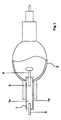
- FIG. 1 shows a discharge lamp in the sense of the inventive solution, which has a current feedthrough 1 and an SiO 2 glass bulb in the form of a discharge vessel 2.
- the discharge vessel 2 has a tubular section 3 in the region of the current leadthrough 1 with an opening into which the current leadthrough 1 is melted.
- the current feedthrough 1 is formed from a composite material 1a, which is surrounded by a thin SiO 2 layer 1b.
- the end of the current feedthrough 1, which projects into the discharge space of the discharge vessel 2, has a tungsten electrode 4.
- the end of the current lead-through 1, which protrudes from the discharge vessel 2, has a contact pin 5 made of molybdenum.
Landscapes
- Vessels And Coating Films For Discharge Lamps (AREA)
- Glass Melting And Manufacturing (AREA)
- Manufacture Of Electron Tubes, Discharge Lamp Vessels, Lead-In Wires, And The Like (AREA)
Description
Die EP 0 930 639 A1 offenbart ebenfalls eine Stromdurchführung mit einem sich über deren Länge ändernden Metall-Gehalt zusammen mit einem SiO2 - Lampenkolben, wobei als geeignete Metalle für das Kompositmaterial neben Molybdän auch Wolfram, Platin, Nickel, Tantal und Zirkon genannt sind. Zum Schutz des Metall-reichen Endes der Stromdurchführung vor Oxidation ist eine Schutzschicht aus Glas, Metalloxid, Edelmetall oder Chrom vorgesehen, die den aus dem Lampenkolben ragenden Teil der Stromdurchführung teilweise bedeckt. Die gasdichte Verschmelzung zwischen Stromdurchführung und Lampenkolben ist in einem Bereich der Stromdurchführung angeordnet, in welchem das Metall mit weniger als 2% im Kompositmaterial vorliegt.
Die Herstellung einer Stromdurchführung mit einer sich über die Länge der Stromdurchführung ändernden Metallkonzentration ist jedoch apparativ aufwendig. Unterschiedliche Pulver müssen hergestellt und in Lagen angeordnet werden. Zudem muss beim Einschmelzen einer Elektrode in die Stromdurchführung auf die elektrische Leitfähigkeit der einzelnen Lagen und damit auf die Eintauchtiefe der Elektrode in die Stromdurchführung geachtet werden, um einen durchgängigen elektrischen Kontakt zu erzeugen. Die Verschmelzung mit dem SiO2-Lampenkolben muss in einem bestimmten Längenabschnitt der Stromdurchführung mit sehr niedriger Metallkonzentration erfolgen, um eine gasdichte Verbindung erreichen zu können. Bei hohen thermischen Belastungen im Bereich der Stromdurchführung kann es zudem bei den nicht oxidationsbeständigen Metallen wie zum Beispiel Molybdän zu Korrosion kommen.
Dabei sollte das SiO2, welches für die Bildung des Kompositmaterials verwendet wird, eine Reinheit von ≥ 97 Gew.-% aufweisen. Verunreinigungen im SiO2, die beispielsweise auf Alkalien oder Erdalkalien zurückzuführen sind, sind demnach bis circa 3 Gew.-% tolerierbar.
Diese Stromdurchführung kann aufgrund der SiO2-Schicht auf ihrer gesamten Länge oder auch nur in einem beliebigen Teilbereich gasdicht mit dem SiO2-Glaskolben verschmolzen werden. Es ist nur ein einziges Kompositpulver zur Herstellung erforderlich. Da die Stromdurchführung über ihre gesamte Länge eine gleichbleibend hohe elektrische Leitfähigkeit aufweist, muss beim Einschmelzen einer Elektrode in die Stromdurchführung nicht auf deren Eintauchtiefe in das Kompositmaterial geachtet werden. Mit dem Anteil an Edelmetall in der Stromdurchführung kann die Einstellung des thermischen Ausdehnungskoeffizienten, der für die Stromdurchführung vorzugsweise im Bereich von < 5.10-6 1/K gewählt wird, erfolgen. Als besonders vorteilhafte Eigenschaft der Stromdurchführung wurde erkannt, dass das Kompositmaterial mit SiO2 und dem Edelmetallanteil in Bereich von ≥ 10 Vol.-% bis ≤ 50 Vol.-% bei Temperaturen von größer circa 1200°C leicht verformbar ist. Bei Temperaturen von größer circa 1600°C biegen sich beispielsweise als Stäbe ausgebildete Stromdurchführungen unter ihrem Eigengewicht rissfrei bis zu einem Winkel von 90° ohne Beeinträchtigung der elektrischen Leitfähigkeit des Materials. Ein Ausrichten beziehungsweise Begradigen einer solchen Stromdurchführung ist dadurch möglich.
Das Auftragen der SiO2-Schicht auf das Kompositmaterial erfolgt vorzugsweise in Form einer Paste oder einer Suspension durch Sprühen oder Drucken oder Tauchen, wobei nachfolgend die SiO2 -Schicht auf dem Kompositmaterial eingebrannt werden sollte.
Der Auftrag der SiO2 -Schicht auf das Kompositmaterial kann aber auch durch Aufdampfen, Sputtem, chemische Abscheidung oder thermisches Spritzen erfolgen.
Dieses Verfahren nutzt die Erkenntnis, dass die Metalle Ruthenium, Rhenium und Iridium, welche flüchtige Oxide bilden, bei Erhitzen des Kompositmaterials auf eine Temperatur ≥ 1600°C in Sauerstoff enthaltender Atmosphäre oberflächlich oxidieren und verdampfen. Es bildet sich während des Glühens eine geschlossene dünne SiO2 -Schicht um das Kompositmaterial aus, die ein weiteres Abdampfen des Metalls verhindert und mit dem SiO2 der Glaskapsel einwandfrei und gasdicht verschmelzbar ist. Die Verschmelzung ist mechanisch so stabil, dass vermutlich ein atomarer Verbund zwischen dem SiO2 der Glaskapsel, der durch Glühen erzeugten SiO2 -Schicht und dem SiO2 im Kompositmaterial gebildet wird.
Besonders vorteilhaft ist es, wenn die Temperatur beim Erhitzen des Pulvergemisches stufenweise auf maximal 1200 - 1600°C erhöht wird.
Kostengünstig ist ein Verfahren, bei welchem das Pulvergemisch vor dem Erhitzen geformt wird. Bewährt hat sich, das Pulvergemisch vor dem Erhitzen formgebend zu pressen oder zu extrudieren. Wird ein ungeformtes Pulvergemisch erhitzt, was selbstverständlich auch möglich ist, so muss das daraus entstandene Kompositmaterial formgebend bearbeitet werden. Aufgrund der höheren Festigkeit des Kompositmaterials muss dies in der Regel durch wenig kostengünstige, spanabhebende Verfahren realisiert werden.
Das SiO2 wird mit einer spezifischen Oberfläche nach BET von 53m2/g und einer mittleren Teilchengröße d50 von 4,4µm eingesetzt. 75Vol.-% SiO2 - Pulver und 25Vol.-% Edelmetallpulver werden unter Zugabe von destilliertem Wasser homogen gemischt und zu einer Paste verarbeitet. Diese Paste wird zu einem Strang mit einem Durchmesser von 2,5mm extrudiert und an Luft getrocknet. Der getrocknete Strang wird in inerter Atmosphäre, vorzugsweise in Argon, mit einer Aufheizgeschwindigkeit von maximal 15°C/min auf 1500°C erhitzt, wobei eine stufenweise Erhitzung durch ein Konstanthalten der Temperatur bei 500°C, 800°C und 1100°C über jeweils 30 min realisiert wird. Die Endtemperatur von 1500°C wird 2h gehalten. Der abgekühlte Kompositstrang mit einem Durchmesser von 1,9mm wird gleichmäßig dünn mit einer Paste belegt, die nur aus dem SiO2 mit einer spezifischen Oberfläche nach BET von 53m2/g und einer mittleren Teilchengröße d50 von 4,4µm unter Zumischung von destilliertem Wasser gebildet ist. Die Paste wird an Luft getrocknet und bei 1550°C über 30min auf dem Kompositstrang eingebrannt. Der mit einer < 0,1 mm dicken SiO2-Schicht beschichtete Kompositstrang beziehungsweise die Stromdurchführung wird auf eine Länge von 25mm geschnitten und ― gegebenenfalls nach Montage einer Elektrode und eines Kontaktstiftes ― in die rohrförmige Öffnung einer SiO2 ― Glaskapsel eingeführt, wobei die rohrförmige Öffnung einen Innendurchmesser von 2mm und einen Außendurchmesser von 5,9mm aufweist. Der Bereich der rohrförmigen Öffnung wird, beispielsweise mit einer Wasserstoff-Flamme, lokal auf circa 1700°C erhitzt. Dadurch kollabiert die rohrförmige Öffnung auf die Stromdurchführung und bildet einen gasdichten, mechanisch stabilen Verbund. Ein Schliffbild der Verbindungsstelle von Glaskapsel zu Stromdurchführung zeigte keine Übergangslinien, die zum Beispiel durch Inhomogenitäten wie Poren, Risse oder Gefügeunterschiede gebildet werden, zwischen Kompositmaterial und SiO2-Schicht beziehungsweise zwischen SiO2-Schicht und Glaskapsel mehr, sondern es war lediglich eine einheitliche SiO2-Phase zu erkennen.
Die so hergestellte Stromdurchführung wird an den Stirnseiten von der SiO2-Schicht befreit und einer elektrischen Leitfähigkeitsprüfung unterzogen. Es ergab sich ein Leitfähigkeits-Wert von 0,047m/Ωmm2.
Das SiO2 wird mit einer spezifischen Oberfläche nach BET von 53m2/g und einer mittleren Teilchengröße d50 von 4,4µm eingesetzt. 75Vol.-% SiO2 ― Pulver und 25Vol.-% Edelmetallpulver werden unter Zugabe von destilliertem Wasser homogen gemischt und zu einer Paste verarbeitet. Diese Paste wird zu einem Strang mit einem Durchmesser von 2,5mm extrudiert und an Luft getrocknet. Der getrocknete Strang wird in inerter Atmosphäre, vorzugsweise in Argon, mit einer Aufheizgeschwindigkeit von maximal 15°C/min auf 1300°C erhitzt, wobei eine stufenweise Erhitzung durch ein Konstanthalten der Temperatur bei 500°C, 800°C und 1100°C über jeweils 30 min realisiert wird. Die Endtemperatur von 1300°C wird 2h gehalten. Nach dem Abkühlen wird die Stromdurchführung auf eine Länge von 15mm geschnitten und in die Stirnseiten des Kompositstranges jeweils ein Sackloch mit einer Tiefe von 3mm und mit einem Durchmesser von 1 mm gebohrt. In eines der Sacklöcher wird eine Wolframdrahtelektrode eingeführt und in das andere ein Kontaktstift aus Molybdän. Die Oberfläche des Kompositstranges wird anschließend gleichmäßig dünn mit einer Paste belegt, die nur aus dem SiO2 mit einer spezifischen Oberfläche nach BET von 53m2/g und einer mittleren Teilchengröße d50 von 4,4µm unter Zumischung von destilliertem Wasser gebildet ist. Die Paste wird an Luft getrocknet und bei 1550°C über 30min auf dem Kompositstrang, der die Elektrode und den Kontaktstift aufweist, eingebrannt.
Es entsteht eine stromleitende, mechanisch stabile Verbindung zwischen Kompositmaterial und Elektrode sowie Kompositmaterial und Kontaktstift.
Das SiO2 wird mit einer spezifischen Oberfläche nach BET von 53m2/g und einer mittleren Teilchengröße d50 von 4,4µm eingesetzt. 75Vol.-% SiO2 ― Pulver und 25Vol.-% Edelmetallpulver werden unter Zugabe von destilliertem Wasser homogen gemischt und zu einer Paste verarbeitet. Diese Paste wird zu einem Strang mit einem Durchmesser von 2,5mm extrudiert und an Luft getrocknet. Der getrocknete Strang wird in inerter Atmosphäre, vorzugsweise in Argon, mit einer Aufheizgeschwindigkeit von maximal 15°C/min auf 1300°C erhitzt, wobei eine stufenweise Erhitzung durch ein Konstanthalten der Temperatur bei 500°C, 800°C und 1100°C über jeweils 30 min realisiert wird. Die Endtemperatur von 1300°C wird 2h gehalten. Der Kompositstrang wird abgekühlt, auf eine Länge von 15mm geschnitten und anschließend bei 1620°C in Luft 30min lang geglüht. Zu Beginn des Glühprozesses ist kurzzeitig ein Abdampfen von Rutheniumoxid festzustellen. Nach dem Abkühlen ist das Kompositmaterial allseitig mit einer dünnen SiO2-Schicht überzogen. Die Stromdurchführung wird an einer Stirnseite auf 1500°C erhitzt und eine Wolframdrahtelektrode circa 2mm in das zähflüssige Kompositmaterial eingedrückt. in gleicher Weise wird der Kontaktstift am anderen Ende der Stromdurchführung befestigt.
Es entsteht eine stromleitende, mechanisch stabile Verbindung zwischen Kompositmaterial und Elektrode sowie Kompositmaterial und Kontaktstift.
Claims (22)
- SiO2-Glaskolben mit mindestens einer Stromdurchführung aus einem gasdichten Kompositmaterial, wobei das Kompositmaterial aus einem Edelmetall mit einem Schmelzpunkt > 1700°C und aus SiO2 gebildet ist und zumindest teilweise mit einer SiO2-Schicht bedeckt ist, dadurch gekennzeichnet, dass das Edelmetall und das SiO2 homogen im Kompositmaterial verteilt sind, dass ein Edelmetallanteil im Kompositmaterial in einem Bereich von ≥ 10Vol% bis ≤ 50Vol% vorhanden ist und dass die SiO2 -Schicht das Kompositmaterial zumindest im Bereich der Verbindung mit dem SiO2 -Glaskolben bedeckt.
- SiO2-Glaskolben nach Anspruch 1, dadurch gekennzeichnet, dass das Kompositmaterial durch Erhitzen eines Pulvergemisches aus Edelmetallpulver und SiO2-Glaspulver gebildet ist.
- SiO2-Glaskolben nach Anspruch 1 oder 2, dadurch gekennzeichnet, dass das Edelmetall aus einer Edelmetall-Legierung gebildet ist.
- SiO2-Glaskolben nach einem der Ansprüche 1 bis 3, dadurch gekennzeichnet, dass das Edelmetall aus Platin und/oder Rhodium gebildet ist.
- SiO2-Glaskolben nach einem der Ansprüche 1 bis 3, dadurch gekennzeichnet, dass das Edelmetall aus Ruthenium und/oder Rhenium und/oder Iridium gebildet ist.
- SiO2 -Glaskolben nach einem der Ansprüche 1 bis 5, dadurch gekennzeichnet, dass die Stromdurchführung eine elektrische Leitfähigkeit von > 0,01m/Ωmm2 aufweist.
- SiO2-Glaskolben nach einem der Ansprüche 1 bis 6, dadurch gekennzeichnet, dass die SiO2 -Schicht eine Dicke im Bereich von 5 - 25µm aufweist.
- SiO2-Glaskolben nach Anspruch 7, dadurch gekennzeichnet, dass die Dicke der SiO2-Schicht 7 - 15µm beträgt.
- SiO2-Glaskolben nach einem der Ansprüche 2 bis 8, dadurch gekennzeichnet, dass das Edelmetallpulver eine spezifische Oberfläche nach BET im Bereich von 0,01. bis 10 m2/g aufweist.
- SiO2-Glaskolben nach einem der Ansprüche 2 bis 9, dadurch gekennzeichnet, dass das Edelmetallpulver eine mittlere Teilchengröße ( d50 ) im Bereich von 3 bis 30µm aufweist.
- SiO2-Glaskolben nach einem der Ansprüche 2 bis 10, dadurch gekennzeichnet, dass das SiO2-Glaspulver eine spezifische Oberfläche nach BET im Bereich von 10 bis 100 m2/g aufweist.
- SiO2-Glaskolben nach einem der Ansprüche 2 bis 11, dadurch gekennzeichnet, dass das SiO2-Glaspulver eine mittlere Teilchengröße ( d50 ) im Bereich von 0,1 bis 10µm aufweist.
- SiO2-Glaskolben nach einem der Ansprüche 1 bis 12, dadurch gekennzeichnet, dass der Edelmetallanteil im Kompositmaterial in einem Bereich von ≥ 10Vol% bis 25Vol% liegt.
- Hochleistungs-Entladungslampe mit einem SiO2 -Glaskolben nach einem der Ansprüche 1 bis 13.
- Verfahren zu Herstellung einer gasdichten Verbindung zwischen einem SiO2 -Glaskolben und einer Stromdurchführung nach einem der Ansprüche 1 bis 13, dadurch gekennzeichnet, dass das Pulvergemisch auf maximal 1200 - 1600°C erhitzt wird, dass nach dem Erhitzen auf das gasdichte Kompositmaterial im Bereich der Verbindung mit dem SiO2 -Glaskolben die SiO2 -Schicht aufgetragen wird, dass die Stromdurchführung in eine Öffnung des SiO2-Glaskolbens eingeführt wird und im Bereich der SiO2-Schicht bei einer Temperatur > 1600°C gasdicht mit dem SiO2 -Glaskolben verbunden wird.
- Verfahren nach Anspruch 15, dadurch gekennzeichnet, dass das Auftragen der SiO2-Schicht auf das Kompositmaterial in Form einer Paste oder einer Suspension durch Sprühen oder Drucken oder Tauchen erfolgt und dass die SiO2 -Schicht auf dem Kompositmaterial eingebrannt wird.
- Verfahren nach Anspruch 15, dadurch gekennzeichnet, dass das Auftragen der SiO2-Schicht auf das Kompositmaterial durch Aufdampfen, Sputtem, chemische Abscheidung oder thermisches Spritzen erfolgt.
- Verfahren zur Herstellung einer gasdichten Verbindung zwischen einem SiO2-Glaskolben und einer Stromdurchführung nach Anspruch 5, dadurch gekennzeichnet, dass das Pulvergemisch auf maximal 1200 - 1600°C erhitzt wird, dass das gasdichte Kompositmaterial nach dem Erhitzen zumindest teilweise bei einer Temperatur ≥ 1600°C in Sauerstoff enthaltender Atmosphäre geglüht wird, wodurch das Edelmetall an der Oberfläche des Kompositmaterials oxidiert und verdampft und zumindest im Bereich der Verbindung mit dem SiO2-Glaskolben der Lampe die SiO2-Schicht erzeugt wird, dass die Stromdurchführung in eine Öffnung des SiO2-Glaskolbens eingeführt wird und im Bereich der SiO2-Schicht bei einer Temperatur > 1600°C gasdicht mit dem SiO2-Glaskolben verbunden wird.
- Verfahren nach Anspruch 18, dadurch gekennzeichnet, dass als Sauerstoff enthaltende Atmosphäre Luft verwendet wird.
- Verfahren nach einem der Ansprüche 15 bis 19, dadurch gekennzeichnet, dass die Temperatur beim Erhitzen stufenweise auf maximal 1200 - 1600°C erhöht wird.
- Verfahren nach einem der Ansprüche 15 bis 20, dadurch gekennzeichnet, dass das Pulvergemisch vor dem Erhitzen geformt wird.
- Verfahren nach Anspruch 21, dadurch gekennzeichnet, dass das Pulvergemisch vor dem Erhitzen gepresst oder extrudiert wird.
Applications Claiming Priority (2)
| Application Number | Priority Date | Filing Date | Title |
|---|---|---|---|
| DE10038841A DE10038841C1 (de) | 2000-08-04 | 2000-08-04 | SiO¶2¶-Glaskolben mit mindestens einer Stromdurchführung, Verfahren zur Herstellung einer gasdichten Verbindung zwischen beiden sowie ihre Verwendung in einer Gasentladungslampe |
| DE10038841 | 2000-08-04 |
Publications (2)
| Publication Number | Publication Date |
|---|---|
| EP1178519A1 EP1178519A1 (de) | 2002-02-06 |
| EP1178519B1 true EP1178519B1 (de) | 2004-02-11 |
Family
ID=7651832
Family Applications (1)
| Application Number | Title | Priority Date | Filing Date |
|---|---|---|---|
| EP01116803A Expired - Lifetime EP1178519B1 (de) | 2000-08-04 | 2001-07-10 | SiO2-Glaskolben mit mindestens einer Stromdurchführung, Verfahren zur Herstellung einer gasdichten Verbindung zwischen beiden sowie ihre Verwendung in einer Gasentladungslampe |
Country Status (4)
| Country | Link |
|---|---|
| US (1) | US6525475B2 (de) |
| EP (1) | EP1178519B1 (de) |
| JP (1) | JP3523617B2 (de) |
| DE (2) | DE10038841C1 (de) |
Families Citing this family (4)
| Publication number | Priority date | Publication date | Assignee | Title |
|---|---|---|---|---|
| JP4613408B2 (ja) * | 1999-10-15 | 2011-01-19 | 日本碍子株式会社 | 高圧放電灯用発光管の製造方法 |
| AT6924U1 (de) * | 2003-05-27 | 2004-05-25 | Plansee Ag | Kaltkathoden-fluoreszenzlampe mit molybdän-stromdurchführungen |
| DE102004015467B4 (de) * | 2004-03-26 | 2007-12-27 | W.C. Heraeus Gmbh | Elektrodensystem mit einer Stromdurchführung durch ein Keramikbauteil |
| RU2465680C2 (ru) * | 2006-12-18 | 2012-10-27 | Конинклейке Филипс Электроникс Н.В. | Газоразрядная лампа высокого давления с керамической газоразрядной оболочкой |
Family Cites Families (11)
| Publication number | Priority date | Publication date | Assignee | Title |
|---|---|---|---|---|
| GB1074124A (en) * | 1963-08-12 | 1967-06-28 | Ass Elect Ind | Improvements in electric devices which have a sealed envelope of vitreous or ceramic insulating refractoy material |
| JPS4625848B1 (de) * | 1966-04-15 | 1971-07-26 | ||
| NL6918746A (de) * | 1969-12-13 | 1971-06-15 | ||
| DE3135035A1 (de) * | 1981-09-04 | 1983-03-24 | Degussa Ag, 6000 Frankfurt | Werkstoff fuer elektrische kontakte und verfahren zu seiner herstellung |
| US5404078A (en) * | 1991-08-20 | 1995-04-04 | Patent-Treuhand-Gesellschaft Fur Elektrische Gluhlampen Mbh | High-pressure discharge lamp and method of manufacture |
| JP3453955B2 (ja) | 1995-10-18 | 2003-10-06 | 東陶機器株式会社 | 放電灯の封止部構造および封止用キャップの製造方法 |
| JPH1040868A (ja) | 1996-07-25 | 1998-02-13 | Ushio Inc | 放電ランプ |
| JP3407564B2 (ja) * | 1996-10-18 | 2003-05-19 | 東陶機器株式会社 | 発光管の封止部用キャップの製造方法 |
| WO1998047169A1 (en) * | 1997-04-11 | 1998-10-22 | Ushio Denki Kabushiki Kaisya | Seal of bulb |
| JP3736710B2 (ja) * | 1997-09-08 | 2006-01-18 | ウシオ電機株式会社 | 管球用電気導入体 |
| US6169366B1 (en) * | 1997-12-24 | 2001-01-02 | Ngk Insulators, Ltd. | High pressure discharge lamp |
-
2000
- 2000-08-04 DE DE10038841A patent/DE10038841C1/de not_active Expired - Fee Related
-
2001
- 2001-07-10 DE DE50101463T patent/DE50101463D1/de not_active Expired - Lifetime
- 2001-07-10 EP EP01116803A patent/EP1178519B1/de not_active Expired - Lifetime
- 2001-07-31 US US09/919,018 patent/US6525475B2/en not_active Expired - Fee Related
- 2001-08-01 JP JP2001234103A patent/JP3523617B2/ja not_active Expired - Fee Related
Also Published As
| Publication number | Publication date |
|---|---|
| DE50101463D1 (de) | 2004-03-18 |
| US20020030446A1 (en) | 2002-03-14 |
| US6525475B2 (en) | 2003-02-25 |
| EP1178519A1 (de) | 2002-02-06 |
| JP2002117809A (ja) | 2002-04-19 |
| DE10038841C1 (de) | 2001-12-20 |
| JP3523617B2 (ja) | 2004-04-26 |
Similar Documents
| Publication | Publication Date | Title |
|---|---|---|
| EP0602530B1 (de) | Verfahren zur Herstellung einer vakuumdichten Abdichtung für ein keramisches Entladungsgefäss und Entladungslampe | |
| EP1111655B1 (de) | Einschmelzfolie und zugehörige Lampe mit dieser Folie | |
| DE2641866A1 (de) | Luftdicht verschlossenes elektrisches einzelteil | |
| DE69920373T2 (de) | Stromzuführungskörper für birne und verfahren zu seiner herstellung | |
| WO2006032522A1 (de) | Verfahren zur herstellung einer abbrandfesten beschichtung, sowie entsprechende schirmung für vakuumschaltkammern | |
| DE112014002069T5 (de) | Keramik-Metall-Bondstruktur und Verfahren zu deren Herstellung | |
| DE10038841C1 (de) | SiO¶2¶-Glaskolben mit mindestens einer Stromdurchführung, Verfahren zur Herstellung einer gasdichten Verbindung zwischen beiden sowie ihre Verwendung in einer Gasentladungslampe | |
| DE2655726C2 (de) | ||
| DE1640218A1 (de) | Thermistor | |
| DE69220865T2 (de) | Werkstoff für Vakuumschalterkontakte und Verfahren zu ihrer Herstellung | |
| DE2747087C2 (de) | Elektrischer Kontakt und Verfahren zu dessen Herstellung | |
| DE69330598T2 (de) | Kontaktmaterial für Vakuumschalter und Herstellungsverfahren dafür | |
| DE10336087A1 (de) | Elektrodensystem mit neuartiger Verbindung, zugehörige Lampe mit dieser Folie und Verfahren zur Herstellung der Verbindung | |
| DE10242035A1 (de) | Einschmelzfolie und zugehörige Lampe mit dieser Folie | |
| DE10257477B4 (de) | Blitzlampe bildender Verbundkörper und Verfahren zum Herstellen eines eine Blitzlampe bildenden Verbundkörpers | |
| DE3043193A1 (de) | Elektrische lampe | |
| DE69409334T2 (de) | Verfahren zur Verbindung einer Molybdän Folie mit einem Teil eines Molybdän Leiters und Herstellungsmethode eines hermetisch eingeschossenen Lampenteils unter Verwendung dieses Verfahrens | |
| DE4308361C2 (de) | Verfahren zur Herstellung einer Verbindung zweier Keramikteile bzw. eines Metall- und eines Keramikteils | |
| EP1351278B1 (de) | Metallhalogenidlampe mit keramischem Entladungsgefäss | |
| DE604107C (de) | Luftdichte Einquetschung der Stromeinfuehrung fuer elektrische Gluehlampen und andere Gefaesse aus Quarzglas | |
| DE2253439C3 (de) | Ternäre Legierung für supraleitende Magneten | |
| DE102005030112A1 (de) | Lötzusatzwerkstoff | |
| DE1812221C3 (de) | Verfahren zum Verbinden eines Leichtmetalles oder Legierungen desselben mit einem nichtmetallischen Material | |
| DE2244241C3 (de) | Verfahren zum Herstellen gasundurchlässiger Röhrenbauteile aus Graphitkörpern | |
| WO2025113752A1 (de) | Hochporöse gerüststruktur-kupferkontakt-herstellungsverfahren und hochporöse gerüststruktur-kupferkontakt-anordnung |
Legal Events
| Date | Code | Title | Description |
|---|---|---|---|
| PUAI | Public reference made under article 153(3) epc to a published international application that has entered the european phase |
Free format text: ORIGINAL CODE: 0009012 |
|
| 17P | Request for examination filed |
Effective date: 20010713 |
|
| AK | Designated contracting states |
Kind code of ref document: A1 Designated state(s): AT BE CH CY DE DK ES FI FR GB GR IE IT LI LU MC NL PT SE TR Kind code of ref document: A1 Designated state(s): BE DE FR GB IT NL |
|
| AX | Request for extension of the european patent |
Free format text: AL;LT;LV;MK;RO;SI |
|
| AKX | Designation fees paid |
Free format text: BE DE FR GB IT NL |
|
| GRAP | Despatch of communication of intention to grant a patent |
Free format text: ORIGINAL CODE: EPIDOSNIGR1 |
|
| GRAS | Grant fee paid |
Free format text: ORIGINAL CODE: EPIDOSNIGR3 |
|
| GRAA | (expected) grant |
Free format text: ORIGINAL CODE: 0009210 |
|
| AK | Designated contracting states |
Kind code of ref document: B1 Designated state(s): BE DE FR GB IT NL |
|
| REG | Reference to a national code |
Ref country code: GB Ref legal event code: FG4D Free format text: NOT ENGLISH |
|
| REG | Reference to a national code |
Ref country code: IE Ref legal event code: FG4D Free format text: GERMAN |
|
| REF | Corresponds to: |
Ref document number: 50101463 Country of ref document: DE Date of ref document: 20040318 Kind code of ref document: P |
|
| GBT | Gb: translation of ep patent filed (gb section 77(6)(a)/1977) |
Effective date: 20040414 |
|
| REG | Reference to a national code |
Ref country code: IE Ref legal event code: FD4D |
|
| ET | Fr: translation filed | ||
| PLBE | No opposition filed within time limit |
Free format text: ORIGINAL CODE: 0009261 |
|
| STAA | Information on the status of an ep patent application or granted ep patent |
Free format text: STATUS: NO OPPOSITION FILED WITHIN TIME LIMIT |
|
| 26N | No opposition filed |
Effective date: 20041112 |
|
| PGFP | Annual fee paid to national office [announced via postgrant information from national office to epo] |
Ref country code: GB Payment date: 20050627 Year of fee payment: 5 |
|
| PGFP | Annual fee paid to national office [announced via postgrant information from national office to epo] |
Ref country code: FR Payment date: 20050712 Year of fee payment: 5 |
|
| NLT1 | Nl: modifications of names registered in virtue of documents presented to the patent office pursuant to art. 16 a, paragraph 1 |
Owner name: W.C. HERAEUS GMBH |
|
| PG25 | Lapsed in a contracting state [announced via postgrant information from national office to epo] |
Ref country code: GB Free format text: LAPSE BECAUSE OF NON-PAYMENT OF DUE FEES Effective date: 20060710 |
|
| PGFP | Annual fee paid to national office [announced via postgrant information from national office to epo] |
Ref country code: IT Payment date: 20060731 Year of fee payment: 6 |
|
| GBPC | Gb: european patent ceased through non-payment of renewal fee |
Effective date: 20060710 |
|
| REG | Reference to a national code |
Ref country code: FR Ref legal event code: ST Effective date: 20070330 |
|
| PG25 | Lapsed in a contracting state [announced via postgrant information from national office to epo] |
Ref country code: FR Free format text: LAPSE BECAUSE OF NON-PAYMENT OF DUE FEES Effective date: 20060731 |
|
| PG25 | Lapsed in a contracting state [announced via postgrant information from national office to epo] |
Ref country code: IT Free format text: LAPSE BECAUSE OF NON-PAYMENT OF DUE FEES Effective date: 20070710 |
|
| REG | Reference to a national code |
Ref country code: NL Ref legal event code: TD Effective date: 20111102 |
|
| REG | Reference to a national code |
Ref country code: DE Ref legal event code: R082 Ref document number: 50101463 Country of ref document: DE Representative=s name: HANS-CHRISTIAN KUEHN, DE |
|
| REG | Reference to a national code |
Ref country code: DE Ref legal event code: R082 Ref document number: 50101463 Country of ref document: DE Representative=s name: KUEHN, HANS-CHRISTIAN, DE Effective date: 20111219 Ref country code: DE Ref legal event code: R081 Ref document number: 50101463 Country of ref document: DE Owner name: HERAEUS MATERIALS TECHNOLOGY GMBH & CO. KG, DE Free format text: FORMER OWNER: W.C. HERAEUS GMBH, 63450 HANAU, DE Effective date: 20111219 |
|
| BECN | Be: change of holder's name |
Owner name: HERAEUS MATERIALS TECHNOLOGY G.M.B.H. & CO. K.G. Effective date: 20120210 |
|
| PGFP | Annual fee paid to national office [announced via postgrant information from national office to epo] |
Ref country code: DE Payment date: 20120720 Year of fee payment: 12 Ref country code: BE Payment date: 20120720 Year of fee payment: 12 |
|
| PGFP | Annual fee paid to national office [announced via postgrant information from national office to epo] |
Ref country code: NL Payment date: 20120719 Year of fee payment: 12 |
|
| BERE | Be: lapsed |
Owner name: HERAEUS MATERIALS TECHNOLOGY G.M.B.H. & CO. K.G. Effective date: 20130731 |
|
| REG | Reference to a national code |
Ref country code: NL Ref legal event code: V1 Effective date: 20140201 |
|
| REG | Reference to a national code |
Ref country code: DE Ref legal event code: R119 Ref document number: 50101463 Country of ref document: DE Effective date: 20140201 |
|
| PG25 | Lapsed in a contracting state [announced via postgrant information from national office to epo] |
Ref country code: BE Free format text: LAPSE BECAUSE OF NON-PAYMENT OF DUE FEES Effective date: 20130731 Ref country code: NL Free format text: LAPSE BECAUSE OF NON-PAYMENT OF DUE FEES Effective date: 20140201 Ref country code: DE Free format text: LAPSE BECAUSE OF NON-PAYMENT OF DUE FEES Effective date: 20140201 |