EP1178223A2 - Hydraulischer Zylinder - Google Patents
Hydraulischer Zylinder Download PDFInfo
- Publication number
- EP1178223A2 EP1178223A2 EP01118223A EP01118223A EP1178223A2 EP 1178223 A2 EP1178223 A2 EP 1178223A2 EP 01118223 A EP01118223 A EP 01118223A EP 01118223 A EP01118223 A EP 01118223A EP 1178223 A2 EP1178223 A2 EP 1178223A2
- Authority
- EP
- European Patent Office
- Prior art keywords
- piston
- hydraulic cylinder
- sealing ring
- cylinder according
- housing
- Prior art date
- Legal status (The legal status is an assumption and is not a legal conclusion. Google has not performed a legal analysis and makes no representation as to the accuracy of the status listed.)
- Withdrawn
Links
- 238000007789 sealing Methods 0.000 claims abstract description 36
- 238000006073 displacement reaction Methods 0.000 claims description 4
- 230000003247 decreasing effect Effects 0.000 description 1
- 230000001627 detrimental effect Effects 0.000 description 1
- 238000011161 development Methods 0.000 description 1
- 230000018109 developmental process Effects 0.000 description 1
- 230000000694 effects Effects 0.000 description 1
- 238000005516 engineering process Methods 0.000 description 1
- 239000012530 fluid Substances 0.000 description 1
- 230000001105 regulatory effect Effects 0.000 description 1
Images


Classifications
-
- F—MECHANICAL ENGINEERING; LIGHTING; HEATING; WEAPONS; BLASTING
- F15—FLUID-PRESSURE ACTUATORS; HYDRAULICS OR PNEUMATICS IN GENERAL
- F15B—SYSTEMS ACTING BY MEANS OF FLUIDS IN GENERAL; FLUID-PRESSURE ACTUATORS, e.g. SERVOMOTORS; DETAILS OF FLUID-PRESSURE SYSTEMS, NOT OTHERWISE PROVIDED FOR
- F15B15/00—Fluid-actuated devices for displacing a member from one position to another; Gearing associated therewith
- F15B15/08—Characterised by the construction of the motor unit
- F15B15/14—Characterised by the construction of the motor unit of the straight-cylinder type
- F15B15/1423—Component parts; Constructional details
- F15B15/1447—Pistons; Piston to piston rod assemblies
- F15B15/1452—Piston sealings
-
- F—MECHANICAL ENGINEERING; LIGHTING; HEATING; WEAPONS; BLASTING
- F15—FLUID-PRESSURE ACTUATORS; HYDRAULICS OR PNEUMATICS IN GENERAL
- F15B—SYSTEMS ACTING BY MEANS OF FLUIDS IN GENERAL; FLUID-PRESSURE ACTUATORS, e.g. SERVOMOTORS; DETAILS OF FLUID-PRESSURE SYSTEMS, NOT OTHERWISE PROVIDED FOR
- F15B15/00—Fluid-actuated devices for displacing a member from one position to another; Gearing associated therewith
- F15B15/08—Characterised by the construction of the motor unit
- F15B15/14—Characterised by the construction of the motor unit of the straight-cylinder type
- F15B15/1423—Component parts; Constructional details
- F15B15/1428—Cylinders
Definitions
- the invention relates to a double-acting hydraulic Cylinder with a housing consisting of two end pieces and one is formed between these arranged cylinder tube, and with a piston that is axially movable relative to the housing.
- the tails are either held together by tie rods or the cylinder barrel is provided with flanges that are screwed to the end pieces are. It is also possible to at least the cylinder barrel to be welded to one of the end pieces. Between the Pistons and the cylinder barrel are provided with circumferential seals, which prevent pressure medium from the one chamber passes into the other chamber. The seals between the Pistons and the cylinder barrel cause friction, however prevents easy movement of the piston. Should the piston must be easily movable, there must be a compromise between the sealing effect and the associated friction found become.
- the invention has for its object a cylinder to create the type mentioned in the work area the piston is easy to move and in one Rest position of the piston no pressure medium from one Chamber passes into the other chamber.
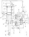
- FIG. 1 shows a differential cylinder hydraulic cylinder 10 according to the invention as a component a position control loop.
- the cylinder 10 serves as a control cylinder of a position-controlled drive. such Drives are e.g. B. to adjust the angle of attack Rotor blades of a wind turbine used.
- the housing the cylinder 10 is composed of a cylinder tube 11 and two end pieces 12 and 13.
- a piston 14 axially movable.
- the piston rod 15 is through that End piece 12 out.
- This end piece is called Inscribed head of the cylinder.
- the other end piece 13 will referred to as the bottom of the cylinder.
- the piston 14 separates the Interior of the cylinder 10 in two chambers 16 and 17.
- the Chamber 16 is via a channel 18 in the end piece 12 with pressure medium acted upon.
- the chamber 17 is via a channel 19 pressurized in the end piece 13.
- a seal 20 prevents pressure medium from the chamber 16 to the outside exit.
- the piston rod 15 is at its free end provided with a thread 21.
- a pump 25 delivers pressure medium from a tank 26 to the Cylinder 10.
- 27 is a continuous valve.
- the Input ports of the continuous valve 27 are with P and T designated, the output connections with A and B.
- Two switching valves are designated 28 and 29.
- the outlet of the pump 25 is via a check valve 30 with a memory 31st connected.
- a displacement sensor shown only schematically 35 detects the position of the piston 14 between the Tails 12 and 13 and converts them into an electrical one Signal xi um, which is a measure of the position of the piston 14th is.
- the signal xi is fed to a controller 36 as an actual value.
- the Controller 36 guides the steady-state valve 27 via an electrical one Line 39 an actuating signal y to the piston of the continuous valve 27 from its rest position shown in FIG. 1 deflects according to the control deviation in such a way that the Control deviation is reduced.
- the piston 14 moves to the right. there pressure medium flows from chamber 17 to tank 26 the piston 14 moves with little friction in the cylinder tube 11, are no seals between the circumference of the piston 14 and the inner wall of the cylinder tube 11 is provided.
- the one with the Reference numeral 40 provided gap between the piston 14 and the cylinder tube 11 acts as a throttle.
- the gap 40 is in 1 and greatly enlarged in the other figures, so that even after repeated copying of the figures still recognizable as a gap.
- the gap 40 is only as large chosen that the piston 14 in the cylinder tube 11 practical can be moved smoothly.
- the sealing ring 42 surrounds the piston 14 when the piston 14 is in the right end position.
- the sealing ring 42 prevents that pressure medium from the chamber 16 into the chamber 17th flows. It also increases the friction between the pistons 14 and the cylinder tube 11. Since the piston 14 in this position not to move, the increased friction affects not detrimental. She even helps with that To keep piston 14 in its rest position.
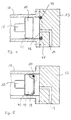
- FIG. 2 shows a different radial design Seal in the end position of the piston 14.
- the sealing ring 42 not in the cylinder tube 11 but in one Groove 43 of the end piece 13 held.
- FIG. 3 shows a further embodiment of a radial one Seal in the end position of the piston 14.
- the sealing ring 42 is held on the piston 44.
- the diameter of the piston 44 is on the end piece 13 facing Side decreased.
- the sealing ring 42 is held in a groove 46.
- the diameter of the piston 14 is in this range chosen so that the sealing ring 42 during the cylinder tube 11 of regular operation just not touched.
- Figures 4 and 5 show two different designs an axial seal between the piston 14 and the end piece 13 in the end position of the piston 14.
- FIG the sealing ring 42 in an annular recess 47 End face 48 of the end piece 13 held.
- 5 is the sealing ring 42 in an annular recess 49 which the End piece 13 facing end 50 of the piston 14 is held.
- Figure 6 shows a detailed representation of a further training an axial seal in the end position of the piston 54.
- the piston 54 is in the Rest position on the end piece 12.
- the piston 54 is on the provide the end piece 12 with a collar 55, which extends in the axial direction.
- the federal government 55 engages the end position in an annular gap 56 and lies down axially sealing against the sealing ring 42.
- the annular gap 56 is limited by the end piece 12 and by the cylinder tube 11.
- the end piece 12 is on the side facing the piston 54 provided with an annular groove 57.
- the annular groove 57 secures the Sealing ring 42 against axial displacement.
- the cylinder 10 can either be controlled so that the Piston 14 rests on the end piece 13 in the rest position (as shown in Figures 1 to 5 for example) or so, that the piston 14 in the rest position on the end piece 12th is present (as shown, for example, in FIG. 6).
Landscapes
- Engineering & Computer Science (AREA)
- Physics & Mathematics (AREA)
- Fluid Mechanics (AREA)
- Mechanical Engineering (AREA)
- General Engineering & Computer Science (AREA)
- Actuator (AREA)
Abstract
Description
- Figur 1
- einen lagegeregelten hydraulischen Zylinder gemäß der Erfindung in schematischer Darstellung,
- Figur 2
- eine Detaildarstellung eines hydraulischen Zylinders gemäß der Erfindung, bei dem der Dichtring radial dichtend im Boden des Zylinders angeordnet ist,
- Figur 3
- eine Detaildarstellung eines hydraulischen Zylinders gemäß der Erfindung, bei dem der Dichtring radial dichtend in einem Bereich kleineren Durchmessers auf dem Kolben angeordnet ist,
- Figur 4
- eine Detaildarstellung eines hydraulischen Zylinders gemäß der Erfindung, bei dem der Dichtring axial dichtend im Boden des Zylinders angeordnet ist,
- Figur 5
- eine Detaildarstellung eines hydraulischen Zylinders gemäß der Erfindung, bei dem der Dichtring axial dichtend in der Stirnseite des Kolbens angeordnet ist, und
- Figur 6
- eine Detaildarstellung eines hydraulischen Zylinders gemäß der Erfindung, bei dem der Dichtring axial dichtend zwischen dem Zylinderrohr und dem Zylinderkopf angeordnet ist.
Claims (12)
- Doppeltwirkender hydraulischer Zylinder mit einem Gehäuse, das aus zwei Endstücken und einem zwischen diesen angeordneten Zylinderrohr gebildet ist, und mit einem gegenüber dem Gehäuse axial bewegbaren Kolben, dadurch gekennzeichnet, daß der Kolben (14; 44; 54) mit geringem Spiel in dem Zylinderrohr (11) geführt ist und daß der Kolben (14) in einer Endlage durch einen Dichtring (42) gegen das Gehäuse (11 bis 13) abgedichtet ist.
- Hydraulischer Zylinder nach Anspruch 1, dadurch gekennzeichnet, daß der Dichtring (42) in dem Gehäuse (11 bis 13) angeordnet ist und den Kolben (14; 44) in der Endlage radial umschließt.
- Hydraulischer Zylinder nach Anspruch 2, dadurch gekennzeichnet, daß der Dichtring (42) in einer Nut (41) des Zylinderrohrs (11) gehalten ist.
- Hydraulischer Zylinder nach Anspruch 2, dadurch gekennzeichnet, daß der Dichtring (42) in einer Nut (43) eines Endstücks (13) gehalten ist.
- Hydraulischer Zylinder nach Anspruch 1, dadurch gekennzeichnet, daß der Durchmesser des Kolbens (44) stirnseitig verringert ist, daß der Dichtring (42) in einer Nut (46) des Bereichs mit verringertem Durchmesser gehalten ist ohne das Zylinderrohr (11) zu berühren und daß der Dichtring (42) in der Endlage radial dichtend an einem Endstück (13) anliegt.
- Hydraulischer Zylinder nach Anspruch 1, dadurch gekennzeichnet, daß der Dichtring (42) den Kolben (14; 54) in der Endlage gegenüber einem Endstück (13; 12) in axialer Richtung abdichtet.
- Hydraulischer Zylinder nach Anspruch 6, dadurch gekennzeichnet, daß der Kolben (54) mit einem sich in axialer Richtung erstreckenden ringförmigen Bund (55) versehen ist, der in der Endlage in einen gehäuseseitigen, in axialer Richtung geöffneten Ringspalt (56) eingreift und daß der Dichtring (42) in dem Ringspalt (56) angeordnet ist.
- Hydraulischer Zylinder nach Anspruch 7, dadurch gekennzeichnet, das der Ringspalt (56) durch das Zylinderrohr (11) und ein Endstück (12) begrenzt ist.
- Hydraulischer Zylinder nach Anspruch 8, dadurch gekennzeichnet, daß das Endstück (12) auf der dem Kolben (54) zugewandten Seite mit einer Ringnut (57) versehen ist.
- Hydraulischer Zylinder nach Anspruch 6, dadurch gekennzeichnet, daß der Dichtring (42) in einer ringförmigen Aussparung (47) der Stirnseite (48) eines Endstücks (13) gehalten ist und in der Endlage an einer stirnseitigen Fläche des Kolbens (14) dichtend anliegt.
- Hydraulischer Zylinder nach Anspruch 6, dadurch gekennzeichnet, daß der Dichtring (42) in einer ringförmigen Aussparung (49) der Stirnseite (50) des Kolbens (14) gehalten ist und in der Endlage des Kolbens (14) an einer stirnseitigen Fläche eines Endstücks (13) dichtend anliegt.
- Hydraulischer Zylinder nach einem der vorhergehenden Ansprüche, dadurch gekennzeichnet, daß ein Wegaufnehmer (35) die Position des Kolbens (14) erfaßt und daß das Ausgangssignal (xi) des Wegaufnehmers (35) einem Lageregler (36) als Istwertsignal zugeführt ist.
Applications Claiming Priority (2)
| Application Number | Priority Date | Filing Date | Title |
|---|---|---|---|
| DE10038061 | 2000-08-04 | ||
| DE10038061A DE10038061A1 (de) | 2000-08-04 | 2000-08-04 | Hydraulischer Zylinder |
Publications (2)
| Publication Number | Publication Date |
|---|---|
| EP1178223A2 true EP1178223A2 (de) | 2002-02-06 |
| EP1178223A3 EP1178223A3 (de) | 2003-11-19 |
Family
ID=7651316
Family Applications (1)
| Application Number | Title | Priority Date | Filing Date |
|---|---|---|---|
| EP01118223A Withdrawn EP1178223A3 (de) | 2000-08-04 | 2001-07-28 | Hydraulischer Zylinder |
Country Status (2)
| Country | Link |
|---|---|
| EP (1) | EP1178223A3 (de) |
| DE (1) | DE10038061A1 (de) |
Cited By (4)
| Publication number | Priority date | Publication date | Assignee | Title |
|---|---|---|---|---|
| CN101995354B (zh) * | 2009-08-27 | 2012-07-04 | 宝山钢铁股份有限公司 | 一种水压试验机压力平衡装置及其控制方法 |
| GB2495852A (en) * | 2011-10-21 | 2013-04-24 | Snecma | A turbomachine blade incidence control system |
| WO2016162024A1 (de) * | 2015-04-09 | 2016-10-13 | Schaeffler Technologies AG & Co. KG | Zugmittelspannanordnung |
| WO2024009044A1 (fr) * | 2022-07-08 | 2024-01-11 | Safran Aircraft Engines | Protection pour circuit de commande d'orientation de pales d'helices de moteur d'aeronef |
Families Citing this family (3)
| Publication number | Priority date | Publication date | Assignee | Title |
|---|---|---|---|---|
| DE20201058U1 (de) | 2002-01-25 | 2002-04-18 | FESTO AG & Co., 73734 Esslingen | Pneumatikantrieb |
| DE102004028396A1 (de) * | 2004-06-14 | 2005-12-29 | Claas Selbstfahrende Erntemaschinen Gmbh | Bodenkopiervorrichtung |
| DE102008030981A1 (de) * | 2008-06-27 | 2009-12-31 | BAM Bundesanstalt für Materialforschung und -prüfung | Hydraulische Positionierungseinheit |
Family Cites Families (9)
| Publication number | Priority date | Publication date | Assignee | Title |
|---|---|---|---|---|
| DE7716671U1 (de) * | 1900-01-01 | Friedrich Bosse Kg, 4955 Hille | ||
| US2724368A (en) * | 1952-10-20 | 1955-11-22 | Cessna Aircraft Co | Working cylinder with integral cylinder head |
| NL6710540A (de) * | 1967-07-31 | 1969-02-04 | ||
| DE2451999C3 (de) * | 1974-11-02 | 1981-07-02 | Messerschmitt-Bölkow-Blohm GmbH, 8000 München | Druckmittelbetriebener Stellmotor |
| DE7810936U1 (de) * | 1977-04-21 | 1978-12-21 | Pont-A-Mousson S.A., Nancy (Frankreich) | Zylinder-Kolben-Vorrichtung, insbesondere für den Support eines Werkzeugträgers einer Bearbeitungsmaschine, insbesondere einer Schleif- oder Poliermaschine |
| JPS6162604A (ja) * | 1984-08-31 | 1986-03-31 | Seiichi Ito | 空気圧シリンダ装置 |
| FI82971C (fi) * | 1988-01-13 | 1991-05-10 | Pimatic Oy | Pneumatisk ventil- och cylinderkombination. |
| DE8915431U1 (de) * | 1989-04-28 | 1990-06-28 | Lupold, Wilhelm, 7243 Vöhringen | Hubkolben für einen Druckzylinderraum |
| DE4409751B4 (de) * | 1994-03-22 | 2005-02-03 | Bayerische Motoren Werke Ag | Pneumatikzylinder |
-
2000
- 2000-08-04 DE DE10038061A patent/DE10038061A1/de not_active Withdrawn
-
2001
- 2001-07-28 EP EP01118223A patent/EP1178223A3/de not_active Withdrawn
Non-Patent Citations (1)
| Title |
|---|
| "Grundlagen und Komponenten der Fluidtechnik-Hyfraulik, Der Hydraulik Trainer Band 1"", 1 January 1991, REXROTH GMBH, pages: 128 - 131 |
Cited By (6)
| Publication number | Priority date | Publication date | Assignee | Title |
|---|---|---|---|---|
| CN101995354B (zh) * | 2009-08-27 | 2012-07-04 | 宝山钢铁股份有限公司 | 一种水压试验机压力平衡装置及其控制方法 |
| GB2495852A (en) * | 2011-10-21 | 2013-04-24 | Snecma | A turbomachine blade incidence control system |
| GB2495852B (en) * | 2011-10-21 | 2018-08-29 | Snecma | Turbomachine blade incidence control system and turbomachine |
| WO2016162024A1 (de) * | 2015-04-09 | 2016-10-13 | Schaeffler Technologies AG & Co. KG | Zugmittelspannanordnung |
| WO2024009044A1 (fr) * | 2022-07-08 | 2024-01-11 | Safran Aircraft Engines | Protection pour circuit de commande d'orientation de pales d'helices de moteur d'aeronef |
| FR3137660A1 (fr) * | 2022-07-08 | 2024-01-12 | Safran Aircraft Engines | Protection pour circuit de commande d’orientation de pales d’hélices de moteur d’aéronef |
Also Published As
| Publication number | Publication date |
|---|---|
| DE10038061A1 (de) | 2002-02-14 |
| EP1178223A3 (de) | 2003-11-19 |
Similar Documents
| Publication | Publication Date | Title |
|---|---|---|
| DE2419311A1 (de) | Mit hoher geschwindigkeit arbeitendes ventil | |
| DE3443265A1 (de) | Regelventil fuer eine verstellpumpe | |
| EP2880316B1 (de) | Ventil, insbesondere vorgesteuertes proportional-wegesitzventil | |
| EP2880315B1 (de) | Ventil, insbesondere vorgesteuertes proportional-wegesitzventil | |
| DE102007020558A1 (de) | Ventilanordnung | |
| DE10038061A1 (de) | Hydraulischer Zylinder | |
| DE3341643A1 (de) | Vorgesteuertes druckentlastungs- und steuerventil | |
| DE3218527C2 (de) | ||
| EP2060837A2 (de) | Stromregelventil | |
| DE10158181C1 (de) | Hydraulischer Druckverstärker | |
| EP1452744B1 (de) | Hydraulische Steueranordnung | |
| DE102022210469A1 (de) | Druckbegrenzungsventilanordnung, modulare Druckbegrenzungsventilanordnung und hydraulische Steueranordnung mit einer derartigen Druckbegrenzungsventilanordnung | |
| DE102014007475B4 (de) | Ventilanordnung zur gesteuerten Druckentlastung fluidgefüllter Leitungen unter erhöhten Sicherheitsanforderungen | |
| WO2003014576A1 (de) | Steuereinrichtung für die kontinuierliche bewegung eines hydraulischen stellmotors | |
| EP0967028B1 (de) | Hydraulische Presse | |
| DE3803009C2 (de) | Hydraulischer Antrieb | |
| EP2452078A1 (de) | Anordnung zur bereitstellung eines veränderbaren drosselquerschnitts für einen fluidstrom | |
| DE3606237A1 (de) | Doppelfahrbremsventil | |
| EP1481167B1 (de) | Ventilanordnung | |
| DE102005047823A1 (de) | Eilgangzylindereinheit | |
| DE2051753A1 (de) | Elektrohydraulisches Servoventil | |
| EP1736671A2 (de) | LS-Steueranordnung und LS-Wegeventil | |
| EP1510699B1 (de) | Verfahren und Vorrichtung zur Flutumschaltung | |
| DE2039339C3 (de) | 4/2-Wegeventil für die Umsteuerung der Druckwasserströme zum Betrieb der Motorzylinder einer Betonpumpe | |
| DE19739412C2 (de) | Vorgesteuertes Schieberventil |
Legal Events
| Date | Code | Title | Description |
|---|---|---|---|
| PUAI | Public reference made under article 153(3) epc to a published international application that has entered the european phase |
Free format text: ORIGINAL CODE: 0009012 |
|
| AK | Designated contracting states |
Kind code of ref document: A2 Designated state(s): AT BE CH CY DE DK ES FI FR GB GR IE IT LI LU MC NL PT SE TR |
|
| AX | Request for extension of the european patent |
Free format text: AL;LT;LV;MK;RO;SI |
|
| RAP1 | Party data changed (applicant data changed or rights of an application transferred) |
Owner name: BOSCH REXROTH AG |
|
| PUAL | Search report despatched |
Free format text: ORIGINAL CODE: 0009013 |
|
| AK | Designated contracting states |
Kind code of ref document: A3 Designated state(s): AT BE CH CY DE DK ES FI FR GB GR IE IT LI LU MC NL PT SE TR |
|
| AX | Request for extension of the european patent |
Extension state: AL LT LV MK RO SI |
|
| AKX | Designation fees paid | ||
| REG | Reference to a national code |
Ref country code: DE Ref legal event code: 8566 |
|
| STAA | Information on the status of an ep patent application or granted ep patent |
Free format text: STATUS: THE APPLICATION IS DEEMED TO BE WITHDRAWN |
|
| 18D | Application deemed to be withdrawn |
Effective date: 20040520 |