EP1178178B1 - Montagebausatz für Flügelrahmen von Schiebetüren oder -fenstern - Google Patents
Montagebausatz für Flügelrahmen von Schiebetüren oder -fenstern Download PDFInfo
- Publication number
- EP1178178B1 EP1178178B1 EP20010401906 EP01401906A EP1178178B1 EP 1178178 B1 EP1178178 B1 EP 1178178B1 EP 20010401906 EP20010401906 EP 20010401906 EP 01401906 A EP01401906 A EP 01401906A EP 1178178 B1 EP1178178 B1 EP 1178178B1
- Authority
- EP
- European Patent Office
- Prior art keywords
- frame
- vertical
- horizontal
- connector
- stile
- Prior art date
- Legal status (The legal status is an assumption and is not a legal conclusion. Google has not performed a legal analysis and makes no representation as to the accuracy of the status listed.)
- Expired - Lifetime
Links
Images


Classifications
-
- E—FIXED CONSTRUCTIONS
- E06—DOORS, WINDOWS, SHUTTERS, OR ROLLER BLINDS IN GENERAL; LADDERS
- E06B—FIXED OR MOVABLE CLOSURES FOR OPENINGS IN BUILDINGS, VEHICLES, FENCES OR LIKE ENCLOSURES IN GENERAL, e.g. DOORS, WINDOWS, BLINDS, GATES
- E06B3/00—Window sashes, door leaves, or like elements for closing wall or like openings; Layout of fixed or moving closures, e.g. windows in wall or like openings; Features of rigidly-mounted outer frames relating to the mounting of wing frames
- E06B3/96—Corner joints or edge joints for windows, doors, or the like frames or wings
- E06B3/964—Corner joints or edge joints for windows, doors, or the like frames or wings using separate connection pieces, e.g. T-connection pieces
- E06B3/9647—Corner joints or edge joints for windows, doors, or the like frames or wings using separate connection pieces, e.g. T-connection pieces the connecting piece being part of or otherwise linked to the window or door fittings
Definitions
- the present invention relates to a door sash frame or sliding window.
- the frame of this opening is formed by means of metal profile elements which form its four sides, ensuring the maintenance vertical of a central panel, glazed or not, these elements having in the corners of the frame a straight cut or slant, said in this case miter, and being abutted mutually to completely surround the panel.
- complementary parts such as connecting brackets or the like, are usually required in the corners of the frame, the branches of these brackets engaging in appropriate housings of two consecutive profiles to secure its elements in each of these angles.
- the object of the present invention is to improve the conventional arrangements mentioned above, by making it possible to eliminate, in the metal profile elements that form the sides of the frame, all the machinings that are ordinarily indispensable, as well as the mounting of additional fastening means. thanks to assembly parts which fulfill all the required functions themselves.
- this chassis comprising only a horizontal lower crossbar under which is mounted a carriage moving on a horizontal rail also carried by the lower profile of the frame of the fixed frame, and a vertical upright forming with the lower cross member of the opening two contiguous sides of the chassis against which two corresponding sides of the central panel supported by it apply, the other two sides of the chassis being devoid of profiles Similar.
- the frame no longer surrounds the four sides of the panel but only comprises metal profiles which respectively constitute a horizontal bottom rail and a vertical upright together forming an L disposed on only two consecutive sides of the panel, its other two sides being devoid of such profiles.
- the document FR-A-1,231,191 describes elements for assembling profiles of a window sash frame, these parts being fixed to the profiles by gluing or pegging.
- the sliding door frame of the door to the window is formed of metal profiles arranged on at least two consecutive sides of the frame, this frame being intended to be mounted inside a fixed fixed frame, and comprising at least one end cap, mounted at the top of a vertical upright of the frame and at least one connecting connection between the lower portion of this upright and the lateral end of a horizontal crossbar, the upright and the cross member constituting two sides constituent parts of the chassis, the plug and the coupling comprising axial and transverse extensions suitable for joining them to the vertical upright and to the horizontal cross member respectively by engagement inside the metal profiles,
- this chassis being characterized in that the transverse extension of the connection fitting, penetrating into the housing of the horizontal crossbar, comprises a carriage or the like, integral with the coupling and comprising wheels or similar displacement means, adapted to cooperate with a rail on which slides the frame vis-à-vis the frame, the plug and the connection having vertical and horizontal holes for mounting fastening screws to the profiles, the threaded ends of the fastening screws mounted in the vertical holes cooperating with
- connection connection has in horizontal cross-section the same external profile as the vertical upright and in vertical straight section the same external profile as the horizontal cross.
- the extensions of the end cap and of the connection fitting have horizontal cross-sections that are smaller than that of their external profile, so that they can penetrate into receiving housings of the same dimensions, formed respectively at the upper part and the lower part of the vertical upright.
- the reference 1 designates as a whole the fixed frame of a door or window frame, this frame comprising four contiguous sides of one to the other, only three of which appear in the drawing, in this case a vertical side 2, an upper horizontal side 3 and a lower threshold element 4, which extends parallel to the upper side 3.
- the four sides of the frame 1 consist of metal profiles, the upper side 3 and the vertical sides such as the side 2, comprising, in the embodiment shown, two parallel grooves, respectively 5 and 6, arranged to allow sliding plan on plan of two leaves 7 and 8 forming the opening and thus slidably mounted inside the frame.
- the view in section and from above of the Figure 2 shows the relative position occupied by the two leaves in the maximum opening position of the opening vis-à-vis the frame.
- the fourth side of the frame of the frame, which forms the lower threshold element 4 advantageously comprises two parallel rails 9 and 10, on which the two leaves 7 and 8 are capable of sliding transversely, independently of one another, to ensure the opening or closing of the door or window, according to their relative positions.
- the leaf 7 is shown in more detail, the second leaf 8 being preferably identical thereto.
- this leaf 7 is made by implementing the provisions that are the subject of the patent application 99 14668 in the name of the applicant, the frame 11 of this leaf thus comprising a vertical upright 12 and a horizontal lower crossbar 13, joined together in one of the angles of the leaf, these two elements alone to ensure the immobilization in the frame of a central panel 14 which is supposed glazed in the example illustrated, but which could be of another nature without affecting the implementation of the provisions of the invention.
- the frame 11 of the leaf 7 of the opening also comprises two covers, essentially decorative, respectively mounted to the upper portion of the central panel 14, opposite the lower cross member 13, and 16, the opposite side side vertically 12, these covers being joined together in the diagonal angle of the one where the amount and the cross connect themselves, and being connected at their opposite ends.
- connection between the vertical upright 12 and the lower horizontal crossbar 13, as well as that of these uprights and passes through the covers 15 and 16, is provided by means of assembly parts according to the invention.
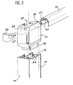
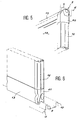
- Figure 3 illustrating the shape and structure of the part joining the upper part of the vertical upright 12 and the hood 15, the Figure 4 that of the part mounted between the lower part of the upright and the corresponding end of the lower horizontal crossbar 13, the Figures 5 and 6 finally, other parts that join the covers 15 and 16 in the opposite corner on the one hand, the same cover 16 and the lower cross member 13 on the other.
- the first of these pieces, represented on the Figure 3 is constituted by a terminal plug, denoted by the reference 17.
- This plug has a horizontal cross section having the same external profile as that of the vertical upright 12.
- it has an axial extension 18 whose cross section is smaller than that of its outer profile, so as to allow its engagement in an open housing 19 of the same shape, formed in the metal section which constitutes the amount 12.
- the cap 17 has in its lateral face facing the cover 15 another transverse extension 20, which engages in a housing 21 of the cover to immobilize it.
- the plug 17 further comprises vertical bores 22, for mounting fixing screws (not shown) cooperating by their threaded end with threaded bores 23 provided in the corresponding walls of the metal section constituting the vertical upright 12, in line with the axial extension 18.
- the end plug 17 comprises at least one horizontal bore 24 for a similar screw serving to immobilize the cover 15, thanks to a threaded bore 25 provided therein with respect to the transverse extension 20.
- a cover 26 provided with a finger 27 is advantageously provided for engaging in the horizontal bore 24 in order to hide the latter once the screw is in place and blocking the cover 15, this cover ensuring in external view, the continuity of the cap terminal 17 and vertical amount 12 on which it fits.
- connecting connection 28 which, in a manner similar to the end plug 17, provides the connection between the lower end of the vertical upright 12 and the horizontal crossmember 13 of the frame 11.
- this connection connection 28 comprises two extensions, one axial 29 in the vertical direction, the other transverse 30 in the horizontal direction, these extensions being provided to engage in housings 31 and 32 of the vertical upright 12 on the one hand, the lower horizontal cross 13 on the other hand.
- one of the fixing screws 33 is this time represented, this screw, engaged in a bore 34 of the coupling 28, being designed to cooperate with a threaded bore 35 of the crosspiece 13.
- a cover 36 with a finger 37 may be mounted in the bore 34 to hide the screw 33.
- the transverse extension 30 supports a carriage 38 provided with wheels 39, this carriage being designed to bear on the rail 9 formed in the lower side 4 forming the threshold of the fixed frame 1 and to ensure the displacement sliding of the corresponding leaf 7.
- FIGS. 5 and 6 still illustrate, on the Figure 5 , a connecting plug 40 between the covers 15 and 16 in the opposite angle of the central panel 14, on the Figure 6 a connection 41 between the cover 16 and the horizontal cross member 13.
- each frame angle comprises only one piece, of the terminal plug or connection connection type as described above, which allows cutting of the profiles to the length just necessary, without unnecessary drops.
Landscapes
- Engineering & Computer Science (AREA)
- Civil Engineering (AREA)
- Structural Engineering (AREA)
- Joining Of Corner Units Of Frames Or Wings (AREA)
- Wing Frames And Configurations (AREA)
- Support Devices For Sliding Doors (AREA)
Claims (3)
- Gleitend öffnender Tür- oder Fensterrahmen (11), der aus Metallprofilen gebildet ist, die wenigstens längs zweier aufeinander folgender Seiten dieses Rahmens angeordnet sind, wobei der Rahmen dazu bestimmt ist, in einer festen Zarge (1) angebracht zu werden, wobei der Rahmen wenigstens einen Endstopfen (17), der im oberen Teil einer Vertikalstrebe (12) des Rahmens angebracht ist, und wenigstens ein Verbindungselement (28) zwischen dem unteren Teil dieser Vertikalstrebe und dem seitlichen Ende einer horizontalen Querstrebe (13) enthält, wobei die Vertikalstrebe und die Querstrebe zwei aufeinander folgende Seiten des Rahmens bilden, wobei der Stopfen und das Verbindungselement axiale und transversale Verlängerungen (18, 20-29, 30) enthalten, mit denen sie mit der Vertikalstrebe bzw. mit der horizontalen Querstrebe jeweils durch Eingriff in dem Innenraum der Metallprofile vereinigt werden können, dadurch gekennzeichnet, dass die transversale Verlängerung (30) des Verbindungselements (28), die in den Aufnahmesitz (32) der horizontalen Querstrebe (13) eindringt, einen Schlitten (38) oder dergleichen aufweist, der mit dem Verbindungselement fest verbunden ist und Räder (39) oder analoge Verlagerungsmittel enthält, die mit einer Schiene (9) zusammenwirken können, auf der der Rahmen (11) gegenüber der Zarge (1) gleitet, und dass der Stopfen und das Verbindungselement vertikale und horizontale Durchlochungen (22, 24, 34) für die Montage von Befestigungsschrauben (33) an den Profilen aufweisen, wobei die Gewindeenden der Befestigungsschrauben, die in den vertikalen Durchlochungen angebracht sind, mit Gewindeelementen zusammenwirken, die mit den Innenwänden der Vertikalstrebe (12) fest verbunden sind, und die Gewindeenden der Befestigungsschrauben, die in den horizontalen Durchlochungen angebracht sind, mit den Gewindeelementen zusammenwirken, die mit den inneren Wänden der horizontalen Querstrebe (13) fest verbunden sind.
- Rahmen nach Anspruch 1, dadurch gekennzeichnet, dass das Verbindungselement (28) einen horizontalen Querschnitt mit dem gleichen Außenprofil wie die Vertikalstrebe (12) und einen vertikalen Querschnitt mit dem gleichen Außenprofil wie die horizontale Querstrebe (13) aufweist.
- Rahmen nach Anspruch 2, dadurch gekennzeichnet, dass die Verlängerungen (18, 19) des Endstopfens (17) und des Verbindungselements (28) horizontale Querschnitte aufweisen, die kleiner als jene ihres Außenprofils sind, derart, dass sie in die Aufnahmesitze (19, 31) mit gleichen Abmessungen eindringen können, die in dem oberen Teil bzw. in dem unteren Teil der Vertikalstrebe (12) ausgebildet sind.
Applications Claiming Priority (2)
| Application Number | Priority Date | Filing Date | Title |
|---|---|---|---|
| FR0010083A FR2812334A1 (fr) | 2000-07-31 | 2000-07-31 | Ensemble de pieces d'assemblage pour chassis d'ouvrant de porte ou fenetre coulissante |
| FR0010083 | 2000-07-31 |
Publications (3)
| Publication Number | Publication Date |
|---|---|
| EP1178178A2 EP1178178A2 (de) | 2002-02-06 |
| EP1178178A3 EP1178178A3 (de) | 2002-10-09 |
| EP1178178B1 true EP1178178B1 (de) | 2008-05-28 |
Family
ID=8853147
Family Applications (1)
| Application Number | Title | Priority Date | Filing Date |
|---|---|---|---|
| EP20010401906 Expired - Lifetime EP1178178B1 (de) | 2000-07-31 | 2001-07-16 | Montagebausatz für Flügelrahmen von Schiebetüren oder -fenstern |
Country Status (4)
| Country | Link |
|---|---|
| EP (1) | EP1178178B1 (de) |
| ES (1) | ES2306697T3 (de) |
| FR (1) | FR2812334A1 (de) |
| PT (1) | PT1178178E (de) |
Cited By (1)
| Publication number | Priority date | Publication date | Assignee | Title |
|---|---|---|---|---|
| RU2746597C1 (ru) * | 2020-04-01 | 2021-04-16 | Общество с ограниченной ответственностью "Индустрия Стекла" | Раздвижная система безрамного остекления |
Families Citing this family (2)
| Publication number | Priority date | Publication date | Assignee | Title |
|---|---|---|---|---|
| DE202010003582U1 (de) * | 2010-03-12 | 2010-07-15 | Veka Ag | Gleiteinsatzelement für den Eckbereich eines Schiebeflügels einer Hebe-Schiebe-Tür |
| CN106193915B (zh) * | 2016-09-27 | 2018-06-29 | 广东亿合门窗科技有限公司 | 重型断桥提升推拉门 |
Family Cites Families (6)
| Publication number | Priority date | Publication date | Assignee | Title |
|---|---|---|---|---|
| US2788097A (en) * | 1953-08-17 | 1957-04-09 | Karl Reinhard | Closure construction for buildings |
| FR1231191A (fr) * | 1959-04-09 | 1960-09-27 | Fenêtre ou analogue à vantaux coulissants | |
| FR1253291A (fr) * | 1959-12-29 | 1961-02-10 | Loiret Elec Metallurg Atel | Procédé et dispositif pour l'assemblage de profilés légers |
| NL7504997A (en) * | 1975-04-28 | 1976-11-01 | Hunlas Bv | Hinged double glazing frame - has hinge formed by external rail on one section engaging with window rail |
| DE3147060C2 (de) * | 1981-11-27 | 1990-05-31 | Heinz Georg Hünibach Thun Baus | Rahmenprofil |
| AT390473B (de) * | 1988-04-19 | 1990-05-10 | Thurnher Julius | Profilrahmen fuer schiebetueren oder -fenster |
-
2000
- 2000-07-31 FR FR0010083A patent/FR2812334A1/fr not_active Withdrawn
-
2001
- 2001-07-16 PT PT01401906T patent/PT1178178E/pt unknown
- 2001-07-16 EP EP20010401906 patent/EP1178178B1/de not_active Expired - Lifetime
- 2001-07-16 ES ES01401906T patent/ES2306697T3/es not_active Expired - Lifetime
Cited By (1)
| Publication number | Priority date | Publication date | Assignee | Title |
|---|---|---|---|---|
| RU2746597C1 (ru) * | 2020-04-01 | 2021-04-16 | Общество с ограниченной ответственностью "Индустрия Стекла" | Раздвижная система безрамного остекления |
Also Published As
| Publication number | Publication date |
|---|---|
| EP1178178A2 (de) | 2002-02-06 |
| FR2812334A1 (fr) | 2002-02-01 |
| ES2306697T3 (es) | 2008-11-16 |
| PT1178178E (pt) | 2008-07-31 |
| EP1178178A3 (de) | 2002-10-09 |
Similar Documents
| Publication | Publication Date | Title |
|---|---|---|
| EP1178178B1 (de) | Montagebausatz für Flügelrahmen von Schiebetüren oder -fenstern | |
| FR2800768A1 (fr) | Dispositif pour le montage et l'immobilisation de consoles de support sur une facade de batiment ou analogue | |
| WO2000037274A1 (fr) | Dispositif de securite pour baie vitree a volet mobile | |
| EP0651122B1 (de) | Verbesserung an Scharnieren zur gelenkigen Verbindung eines Flügels an einem Rahmen | |
| FR2686646A1 (fr) | Penture reglable pour le ferrage notamment de portes ou de volets, cavalier d'assemblage et procede d'assemblage d'une telle penture. | |
| FR2570748A1 (fr) | Dispositif d'assemblage simplifie des differentes parties de fenetres, portes et ouvertures similaires, en bois, ainsi que tout agencement de meubles | |
| EP2053189A2 (de) | Rahmen mit Fenster- oder Türflügel | |
| EP1026356B1 (de) | Glaspaneel mit Mitteln zum Verbinden an eine angrenzende Struktur | |
| FR2611797A1 (fr) | Charniere, notamment pour armoire electrique, et armoire, en particulier armoire electrique, comportant une telle charniere | |
| EP2832949A1 (de) | Steuerungssystem für die Lamellen von Jalousien, und entsprechende Jalousie | |
| EP1605119B1 (de) | Verriegelungsanordnung für Tür, Fenster oder verschiebbare Fenstertür | |
| FR2681403A1 (fr) | Dispositif d'assemblage pour profiles d'ossature, ossature correspondante, et armoire, en particulier armoire pour appareillages electriques, mettant en óoeuvre une telle ossature. | |
| FR2967442A1 (fr) | Huisserie pour porte ou fenetre composee de deux plaques de platre | |
| BE1019663A4 (fr) | Ensemble chambranle contre-chambranle. | |
| EP0773332A1 (de) | Dichtungsanordnung zwischen den Rahmen von Vorhangfassaden | |
| FR2770867A1 (fr) | Barriere a armature porteuse integree et portail en faisant application | |
| EP0911477B1 (de) | Tür- oder Fenster- oder analoger Rahmen mit verdecktem Scharniergelenk | |
| FR2764966A1 (fr) | Dispositif pour rigidifier un assemblage de profiles metalliques dans un chassis de porte, fenetre ou analogue | |
| FR3023574A1 (fr) | Coffre-tunnel, plaque de fermeture d'un demi-coffre, pourvu d'un moyen de liaison entre un dormant et un linteau preexistant | |
| FR2981679A1 (fr) | Huisserie metallique a caractere universel | |
| FR2690553A1 (fr) | Système d'assemblage de panneaux, notamment de panneaux blindés constituant une cage de Faraday. | |
| FR2544009A3 (fr) | Porte de securite constituee de plinthes metalliques et de panneaux de verre | |
| EP1058766A1 (de) | Scharnierzapfen mit elastischer einstellung, verwendung an einer rotierbaren platte und tür | |
| FR2764934A1 (fr) | Survitrage a elements de fixation et d'ouverture non-apparents | |
| FR2697126A1 (fr) | Battant de porte et armoire, notamment armoire électrique, équipée d'un tel battant de porte. |
Legal Events
| Date | Code | Title | Description |
|---|---|---|---|
| PUAI | Public reference made under article 153(3) epc to a published international application that has entered the european phase |
Free format text: ORIGINAL CODE: 0009012 |
|
| AK | Designated contracting states |
Kind code of ref document: A2 Designated state(s): AT BE CH CY DE DK ES FI FR GB GR IE IT LI LU MC NL PT SE TR |
|
| AX | Request for extension of the european patent |
Free format text: AL;LT;LV;MK;RO;SI |
|
| PUAL | Search report despatched |
Free format text: ORIGINAL CODE: 0009013 |
|
| 17P | Request for examination filed |
Effective date: 20020710 |
|
| AK | Designated contracting states |
Kind code of ref document: A3 Designated state(s): AT BE CH CY DE DK ES FI FR GB GR IE IT LI LU MC NL PT SE TR |
|
| AX | Request for extension of the european patent |
Free format text: AL;LT;LV;MK;RO;SI |
|
| RIC1 | Information provided on ipc code assigned before grant |
Free format text: 7E 06B 3/46 A, 7E 06B 3/964 B |
|
| AKX | Designation fees paid |
Designated state(s): ES FR GB IE PT |
|
| REG | Reference to a national code |
Ref country code: DE Ref legal event code: 8566 |
|
| 17Q | First examination report despatched |
Effective date: 20060811 |
|
| RAP1 | Party data changed (applicant data changed or rights of an application transferred) |
Owner name: HYDRO BUILDING SYSTEMS |
|
| GRAP | Despatch of communication of intention to grant a patent |
Free format text: ORIGINAL CODE: EPIDOSNIGR1 |
|
| GRAS | Grant fee paid |
Free format text: ORIGINAL CODE: EPIDOSNIGR3 |
|
| GRAA | (expected) grant |
Free format text: ORIGINAL CODE: 0009210 |
|
| AK | Designated contracting states |
Kind code of ref document: B1 Designated state(s): ES FR GB IE PT |
|
| REG | Reference to a national code |
Ref country code: GB Ref legal event code: FG4D Free format text: NOT ENGLISH |
|
| REG | Reference to a national code |
Ref country code: PT Ref legal event code: SC4A Free format text: AVAILABILITY OF NATIONAL TRANSLATION Effective date: 20080721 |
|
| REG | Reference to a national code |
Ref country code: IE Ref legal event code: FG4D Free format text: LANGUAGE OF EP DOCUMENT: FRENCH |
|
| REG | Reference to a national code |
Ref country code: ES Ref legal event code: FG2A Ref document number: 2306697 Country of ref document: ES Kind code of ref document: T3 |
|
| PLBE | No opposition filed within time limit |
Free format text: ORIGINAL CODE: 0009261 |
|
| STAA | Information on the status of an ep patent application or granted ep patent |
Free format text: STATUS: NO OPPOSITION FILED WITHIN TIME LIMIT |
|
| 26N | No opposition filed |
Effective date: 20090303 |
|
| PGFP | Annual fee paid to national office [announced via postgrant information from national office to epo] |
Ref country code: PT Payment date: 20110630 Year of fee payment: 11 |
|
| PGFP | Annual fee paid to national office [announced via postgrant information from national office to epo] |
Ref country code: IE Payment date: 20110721 Year of fee payment: 11 |
|
| PGFP | Annual fee paid to national office [announced via postgrant information from national office to epo] |
Ref country code: GB Payment date: 20110721 Year of fee payment: 11 Ref country code: ES Payment date: 20110726 Year of fee payment: 11 Ref country code: FR Payment date: 20110810 Year of fee payment: 11 |
|
| REG | Reference to a national code |
Ref country code: PT Ref legal event code: MM4A Free format text: LAPSE DUE TO NON-PAYMENT OF FEES Effective date: 20130116 |
|
| GBPC | Gb: european patent ceased through non-payment of renewal fee |
Effective date: 20120716 |
|
| REG | Reference to a national code |
Ref country code: FR Ref legal event code: ST Effective date: 20130329 |
|
| PG25 | Lapsed in a contracting state [announced via postgrant information from national office to epo] |
Ref country code: FR Free format text: LAPSE BECAUSE OF NON-PAYMENT OF DUE FEES Effective date: 20120731 Ref country code: GB Free format text: LAPSE BECAUSE OF NON-PAYMENT OF DUE FEES Effective date: 20120716 |
|
| REG | Reference to a national code |
Ref country code: IE Ref legal event code: MM4A |
|
| PG25 | Lapsed in a contracting state [announced via postgrant information from national office to epo] |
Ref country code: PT Free format text: LAPSE BECAUSE OF NON-PAYMENT OF DUE FEES Effective date: 20130116 |
|
| PG25 | Lapsed in a contracting state [announced via postgrant information from national office to epo] |
Ref country code: IE Free format text: LAPSE BECAUSE OF NON-PAYMENT OF DUE FEES Effective date: 20120716 |
|
| REG | Reference to a national code |
Ref country code: ES Ref legal event code: FD2A Effective date: 20131022 |
|
| PG25 | Lapsed in a contracting state [announced via postgrant information from national office to epo] |
Ref country code: ES Free format text: LAPSE BECAUSE OF NON-PAYMENT OF DUE FEES Effective date: 20120717 |