EP1178178B1 - Assembly kit for wing frames of sliding doors or windows - Google Patents
Assembly kit for wing frames of sliding doors or windows Download PDFInfo
- Publication number
- EP1178178B1 EP1178178B1 EP20010401906 EP01401906A EP1178178B1 EP 1178178 B1 EP1178178 B1 EP 1178178B1 EP 20010401906 EP20010401906 EP 20010401906 EP 01401906 A EP01401906 A EP 01401906A EP 1178178 B1 EP1178178 B1 EP 1178178B1
- Authority
- EP
- European Patent Office
- Prior art keywords
- frame
- vertical
- horizontal
- connector
- stile
- Prior art date
- Legal status (The legal status is an assumption and is not a legal conclusion. Google has not performed a legal analysis and makes no representation as to the accuracy of the status listed.)
- Expired - Lifetime
Links
Images


Classifications
-
- E—FIXED CONSTRUCTIONS
- E06—DOORS, WINDOWS, SHUTTERS, OR ROLLER BLINDS IN GENERAL; LADDERS
- E06B—FIXED OR MOVABLE CLOSURES FOR OPENINGS IN BUILDINGS, VEHICLES, FENCES OR LIKE ENCLOSURES IN GENERAL, e.g. DOORS, WINDOWS, BLINDS, GATES
- E06B3/00—Window sashes, door leaves, or like elements for closing wall or like openings; Layout of fixed or moving closures, e.g. windows in wall or like openings; Features of rigidly-mounted outer frames relating to the mounting of wing frames
- E06B3/96—Corner joints or edge joints for windows, doors, or the like frames or wings
- E06B3/964—Corner joints or edge joints for windows, doors, or the like frames or wings using separate connection pieces, e.g. T-connection pieces
- E06B3/9647—Corner joints or edge joints for windows, doors, or the like frames or wings using separate connection pieces, e.g. T-connection pieces the connecting piece being part of or otherwise linked to the window or door fittings
Definitions
- the present invention relates to a door sash frame or sliding window.
- the frame of this opening is formed by means of metal profile elements which form its four sides, ensuring the maintenance vertical of a central panel, glazed or not, these elements having in the corners of the frame a straight cut or slant, said in this case miter, and being abutted mutually to completely surround the panel.
- complementary parts such as connecting brackets or the like, are usually required in the corners of the frame, the branches of these brackets engaging in appropriate housings of two consecutive profiles to secure its elements in each of these angles.
- the object of the present invention is to improve the conventional arrangements mentioned above, by making it possible to eliminate, in the metal profile elements that form the sides of the frame, all the machinings that are ordinarily indispensable, as well as the mounting of additional fastening means. thanks to assembly parts which fulfill all the required functions themselves.
- this chassis comprising only a horizontal lower crossbar under which is mounted a carriage moving on a horizontal rail also carried by the lower profile of the frame of the fixed frame, and a vertical upright forming with the lower cross member of the opening two contiguous sides of the chassis against which two corresponding sides of the central panel supported by it apply, the other two sides of the chassis being devoid of profiles Similar.
- the frame no longer surrounds the four sides of the panel but only comprises metal profiles which respectively constitute a horizontal bottom rail and a vertical upright together forming an L disposed on only two consecutive sides of the panel, its other two sides being devoid of such profiles.
- the document FR-A-1,231,191 describes elements for assembling profiles of a window sash frame, these parts being fixed to the profiles by gluing or pegging.
- the sliding door frame of the door to the window is formed of metal profiles arranged on at least two consecutive sides of the frame, this frame being intended to be mounted inside a fixed fixed frame, and comprising at least one end cap, mounted at the top of a vertical upright of the frame and at least one connecting connection between the lower portion of this upright and the lateral end of a horizontal crossbar, the upright and the cross member constituting two sides constituent parts of the chassis, the plug and the coupling comprising axial and transverse extensions suitable for joining them to the vertical upright and to the horizontal cross member respectively by engagement inside the metal profiles,
- this chassis being characterized in that the transverse extension of the connection fitting, penetrating into the housing of the horizontal crossbar, comprises a carriage or the like, integral with the coupling and comprising wheels or similar displacement means, adapted to cooperate with a rail on which slides the frame vis-à-vis the frame, the plug and the connection having vertical and horizontal holes for mounting fastening screws to the profiles, the threaded ends of the fastening screws mounted in the vertical holes cooperating with
- connection connection has in horizontal cross-section the same external profile as the vertical upright and in vertical straight section the same external profile as the horizontal cross.
- the extensions of the end cap and of the connection fitting have horizontal cross-sections that are smaller than that of their external profile, so that they can penetrate into receiving housings of the same dimensions, formed respectively at the upper part and the lower part of the vertical upright.
- the reference 1 designates as a whole the fixed frame of a door or window frame, this frame comprising four contiguous sides of one to the other, only three of which appear in the drawing, in this case a vertical side 2, an upper horizontal side 3 and a lower threshold element 4, which extends parallel to the upper side 3.
- the four sides of the frame 1 consist of metal profiles, the upper side 3 and the vertical sides such as the side 2, comprising, in the embodiment shown, two parallel grooves, respectively 5 and 6, arranged to allow sliding plan on plan of two leaves 7 and 8 forming the opening and thus slidably mounted inside the frame.
- the view in section and from above of the Figure 2 shows the relative position occupied by the two leaves in the maximum opening position of the opening vis-à-vis the frame.
- the fourth side of the frame of the frame, which forms the lower threshold element 4 advantageously comprises two parallel rails 9 and 10, on which the two leaves 7 and 8 are capable of sliding transversely, independently of one another, to ensure the opening or closing of the door or window, according to their relative positions.
- the leaf 7 is shown in more detail, the second leaf 8 being preferably identical thereto.
- this leaf 7 is made by implementing the provisions that are the subject of the patent application 99 14668 in the name of the applicant, the frame 11 of this leaf thus comprising a vertical upright 12 and a horizontal lower crossbar 13, joined together in one of the angles of the leaf, these two elements alone to ensure the immobilization in the frame of a central panel 14 which is supposed glazed in the example illustrated, but which could be of another nature without affecting the implementation of the provisions of the invention.
- the frame 11 of the leaf 7 of the opening also comprises two covers, essentially decorative, respectively mounted to the upper portion of the central panel 14, opposite the lower cross member 13, and 16, the opposite side side vertically 12, these covers being joined together in the diagonal angle of the one where the amount and the cross connect themselves, and being connected at their opposite ends.
- connection between the vertical upright 12 and the lower horizontal crossbar 13, as well as that of these uprights and passes through the covers 15 and 16, is provided by means of assembly parts according to the invention.
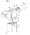
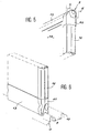
- Figure 3 illustrating the shape and structure of the part joining the upper part of the vertical upright 12 and the hood 15, the Figure 4 that of the part mounted between the lower part of the upright and the corresponding end of the lower horizontal crossbar 13, the Figures 5 and 6 finally, other parts that join the covers 15 and 16 in the opposite corner on the one hand, the same cover 16 and the lower cross member 13 on the other.
- the first of these pieces, represented on the Figure 3 is constituted by a terminal plug, denoted by the reference 17.
- This plug has a horizontal cross section having the same external profile as that of the vertical upright 12.
- it has an axial extension 18 whose cross section is smaller than that of its outer profile, so as to allow its engagement in an open housing 19 of the same shape, formed in the metal section which constitutes the amount 12.
- the cap 17 has in its lateral face facing the cover 15 another transverse extension 20, which engages in a housing 21 of the cover to immobilize it.
- the plug 17 further comprises vertical bores 22, for mounting fixing screws (not shown) cooperating by their threaded end with threaded bores 23 provided in the corresponding walls of the metal section constituting the vertical upright 12, in line with the axial extension 18.
- the end plug 17 comprises at least one horizontal bore 24 for a similar screw serving to immobilize the cover 15, thanks to a threaded bore 25 provided therein with respect to the transverse extension 20.
- a cover 26 provided with a finger 27 is advantageously provided for engaging in the horizontal bore 24 in order to hide the latter once the screw is in place and blocking the cover 15, this cover ensuring in external view, the continuity of the cap terminal 17 and vertical amount 12 on which it fits.
- connecting connection 28 which, in a manner similar to the end plug 17, provides the connection between the lower end of the vertical upright 12 and the horizontal crossmember 13 of the frame 11.
- this connection connection 28 comprises two extensions, one axial 29 in the vertical direction, the other transverse 30 in the horizontal direction, these extensions being provided to engage in housings 31 and 32 of the vertical upright 12 on the one hand, the lower horizontal cross 13 on the other hand.
- one of the fixing screws 33 is this time represented, this screw, engaged in a bore 34 of the coupling 28, being designed to cooperate with a threaded bore 35 of the crosspiece 13.
- a cover 36 with a finger 37 may be mounted in the bore 34 to hide the screw 33.
- the transverse extension 30 supports a carriage 38 provided with wheels 39, this carriage being designed to bear on the rail 9 formed in the lower side 4 forming the threshold of the fixed frame 1 and to ensure the displacement sliding of the corresponding leaf 7.
- FIGS. 5 and 6 still illustrate, on the Figure 5 , a connecting plug 40 between the covers 15 and 16 in the opposite angle of the central panel 14, on the Figure 6 a connection 41 between the cover 16 and the horizontal cross member 13.
- each frame angle comprises only one piece, of the terminal plug or connection connection type as described above, which allows cutting of the profiles to the length just necessary, without unnecessary drops.
Description
La présente invention est relative à un châssis d'ouvrant de porte ou fenêtre coulissante.The present invention relates to a door sash frame or sliding window.
Dans un ouvrant de porte ou fenêtre classique, comportant notamment un ou plusieurs vantaux montés à coulissement transversal dans un cadre dormant fixe, le châssis de cet ouvrant est constitué au moyen d'éléments de profilés métalliques qui forment ses quatre côtés, en assurant le maintien vertical d'un panneau central, vitré ou non, ces éléments présentant dans les angles du châssis une coupe droite ou en biais, dite dans ce cas en onglet, et étant aboutés mutuellement pour entourer complètement le panneau.In a conventional door or window opening, comprising in particular one or more leaves mounted to slide transversely in a fixed fixed frame, the frame of this opening is formed by means of metal profile elements which form its four sides, ensuring the maintenance vertical of a central panel, glazed or not, these elements having in the corners of the frame a straight cut or slant, said in this case miter, and being abutted mutually to completely surround the panel.
Dans un tel agencement, des pièces complémentaires, du genre équerres de liaison ou analogues, sont habituellement nécessaires dans les angles du châssis, les branches de ces équerres s'engageant dans des logements appropriés de deux profilés consécutifs afin de solidariser ses éléments dans chacun de ces angles.In such an arrangement, complementary parts, such as connecting brackets or the like, are usually required in the corners of the frame, the branches of these brackets engaging in appropriate housings of two consecutive profiles to secure its elements in each of these angles.
Le document
Cette solution exige l'usage d'outillages spéciaux pour la réalisation, la mise en place et le blocage de ces équerres, indépendamment de certaines autres adaptations généralement indispensables, qui consistent notamment à gruger les toiles des profilés pour permettre le passage dans l'élément inférieur du châssis d'un rail ou similaire porté par le dormant et sur lequel coulisse le vantail de l'ouvrant, ou encore à percer ces mêmes toiles pour le montage de vis de fixation des équerres, à fraiser des lumières de drainage des eaux de pluie ou autres qui peuvent ruisseler sur la surface du vantail, et enfin à aménager des moyens pour fixer sur le châssis des éléments de guidage et/ou de butée, nécessaires à son utilisation.This solution requires the use of special tools for the realization, the establishment and the blocking of these brackets, independently of certain other generally necessary adaptations, which consist in particular to gruwe the webs of the profiles to allow the passage in the element lower frame of a rail or the like carried by the frame and on which slides the leaf of the opening, or to drill these same webs for mounting screws for fixing the brackets, milling lights drainage water rain or other that can run off on the leaf surface, and finally to arrange means for fixing on the frame guiding and / or abutment elements, necessary for its use.
La présente invention a pour but d'améliorer les dispositions classiques rappelées ci-dessus, en permettant de supprimer, dans les éléments en profilés métalliques qui forment les côtés du châssis, tous les usinages ordinairement indispensables, ainsi que le montage de moyens de fixation additionnels, grâce à des pièces d'assemblage accomplissant elles-mêmes l'ensemble des fonctions requises.The object of the present invention is to improve the conventional arrangements mentioned above, by making it possible to eliminate, in the metal profile elements that form the sides of the frame, all the machinings that are ordinarily indispensable, as well as the mounting of additional fastening means. thanks to assembly parts which fulfill all the required functions themselves.
Plus particulièrement encore, quoique de manière non exclusive, l'invention s'applique à un châssis de porte ou fenêtre coulissante, du genre de celui décrit et revendiqué dans la demande de brevet français
Grâce à ces dispositions, le châssis n'entoure plus les quatre côtés du panneau mais comporte seulement des profilés métalliques qui constituent respectivement une traverse inférieure horizontale et un montant vertical formant ensemble un L disposé selon deux côtés consécutifs seulement du panneau, ses deux autres côtés étant dépourvus de tels profilés.Thanks to these arrangements, the frame no longer surrounds the four sides of the panel but only comprises metal profiles which respectively constitute a horizontal bottom rail and a vertical upright together forming an L disposed on only two consecutive sides of the panel, its other two sides being devoid of such profiles.
Le document
Selon l'invention, le châssis d'ouvrant coulissant de porte au fenêtre est formé de profilés métalliques disposés selon au moins deux côtés consécutifs du châssis, ce châssis étant destiné à être monté à l'intérieur d'un cadre dormant fixe, et comprenant au moins un bouchon terminal, monté en partie supérieure d'un montant vertical du châssis et au moins un raccord de liaison entre la partie inférieure de ce montant et l'extrémité latérale d'une traverse horizontale, le montant et la traverse constituant deux côtés constitutifs du châssis, le bouchon et le raccord comprenant des extensions axiales et transversales propres à les réunir au montant vertical et à la traverse horizontale respectivement par engagement à l'intérieur des profilés métalliques, ce châssis étant caractérisé en ce que l'extension transversale du raccord de liaison, pénétrant dans le logement de la traverse horizontale, comporte un chariot ou similaire, solidaire du raccord et comportant des roues ou moyens de déplacement analogues, aptes à coopérer avec un rail sur lequel coulisse le châssis vis-à-vis du dormant, le bouchon et le raccord comportant des perçages verticaux et horizontaux pour le montage de vis de fixation aux profilés, les extrémités filetées des vis de fixation montées dans les perçages verticaux coopérant avec des éléments taraudés solidaires des parois internes du montant vertical, et les extrémités filetées des vis de fixation montées dans les perçages horizontaux coopérant avec des éléments taraudés solidaires des parois internes de la traverse horizontale.According to the invention, the sliding door frame of the door to the window is formed of metal profiles arranged on at least two consecutive sides of the frame, this frame being intended to be mounted inside a fixed fixed frame, and comprising at least one end cap, mounted at the top of a vertical upright of the frame and at least one connecting connection between the lower portion of this upright and the lateral end of a horizontal crossbar, the upright and the cross member constituting two sides constituent parts of the chassis, the plug and the coupling comprising axial and transverse extensions suitable for joining them to the vertical upright and to the horizontal cross member respectively by engagement inside the metal profiles, this chassis being characterized in that the transverse extension of the connection fitting, penetrating into the housing of the horizontal crossbar, comprises a carriage or the like, integral with the coupling and comprising wheels or similar displacement means, adapted to cooperate with a rail on which slides the frame vis-à-vis the frame, the plug and the connection having vertical and horizontal holes for mounting fastening screws to the profiles, the threaded ends of the fastening screws mounted in the vertical holes cooperating with elements threaded threads integral with the inner walls of the vertical upright, and the threaded ends of the fastening screws mounted in the horizontal bores cooperating with threaded elements integral with the internal walls of the horizontal cross member.
De préférence, le raccord de liaison présente en section droite horizontale le même profil extérieur que le montant vertical et en section droite verticale le même profil extérieur que la traverse horizontale.Preferably, the connection connection has in horizontal cross-section the same external profile as the vertical upright and in vertical straight section the same external profile as the horizontal cross.
De plus et selon une caractéristique particulière, les extensions du bouchon terminal et du raccord de liaison présentent des sections droites horizontales plus réduites que celle de leur profil extérieur, de manière à ce qu'elles puissent pénétrer dans des logements de réception de mêmes dimensions, ménagés respectivement à la partie supérieure et à la partie inférieure du montant vertical.In addition and according to a particular characteristic, the extensions of the end cap and of the connection fitting have horizontal cross-sections that are smaller than that of their external profile, so that they can penetrate into receiving housings of the same dimensions, formed respectively at the upper part and the lower part of the vertical upright.
D'autres caractéristiques de pièces d'assemblage pour ouvrant de porte ou fenêtre coulissante, établies conformément à l'invention, apparaîtront encore à travers la description qui suit d'exemples de réalisation, donnés à titre indicatif et non limitatif, en référence aux dessins annexés sur lesquels :
- La
Figure 1 est une vue schématique en perspective d'un châssis coulissant, notamment du genre décrit dans la demande de brevet françaisFR-A-2 801 337 - La
Figure 2 est une vue en coupe transversale et de dessus du châssis coulissant de laFigure 1 . - La
Figure 3 est une vue en perspective, à plus grande échelle, d'un bouchon terminal constituant une des pièces d'assemblage selon l'invention, prévue pour être montée à la partie supérieure d'un montant vertical du châssis. - La
Figure 4 est une vue en perspective, analogue à laFigure 3 , illustrant le raccord de liaison monté à la partie inférieure du même montant vertical et raccordant celui-ci à la traverse horizontale du châssis. - Les
Figures 5 et 6 sont des vues en perspective illustrant d'un bouchon et d'un raccord simplifiés, montés dans les angles du châssis opposés aux bouchon et raccord illustrés sur lesFigures 3 et4 respectivement.
- The
Figure 1 is a schematic perspective view of a sliding frame, in particular of the type described in the French patent applicationFR-A-2 801 337 - The
Figure 2 is a cross-sectional view from above of the sliding frame of theFigure 1 . - The
Figure 3 is a perspective view, on a larger scale, of a terminal plug constituting one of the assembly parts according to the invention, intended to be mounted at the upper part of a vertical upright of the frame. - The
Figure 4 is a perspective view, similar to theFigure 3 , illustrating the connection fitting mounted at the bottom of the same vertical upright and connecting it to the horizontal cross member of the frame. - The
Figures 5 and 6 are perspective views illustrating a simplified plug and connector, mounted in the corners of the frame opposed to the plug and fitting illustrated in the drawings.Figures 3 and4 respectively.
Sur la
Les quatre côtés du cadre 1 sont constitués de profilés métalliques, le côté supérieur 3 et les côtés verticaux tels que le côté 2, comportant, dans l'exemple de réalisation représenté, deux rainures parallèles, respectivement 5 et 6, aménagées pour permettre le coulissement plan sur plan de deux vantaux 7 et 8 formant l'ouvrant et montés ainsi à coulissement à l'intérieur du cadre. La vue en coupe et de dessus de la
Le quatrième côté du cadre du dormant, qui forme l'élément de seuil inférieur 4, comporte avantageusement deux rails parallèles 9 et 10, sur lesquels les deux vantaux 7 et 8 sont susceptibles de glisser transversalement, indépendamment l'un de l'autre, pour assurer l'ouverture ou la fermeture de la porte ou fenêtre, selon leurs positions relatives.The fourth side of the frame of the frame, which forms the
Dans l'exemple considéré, le vantail 7 est représenté de manière plus détaillée, le second vantail 8 étant de préférence identique à celui-ci.In the example considered, the
De préférence, ce vantail 7 est réalisé en mettant en oeuvre les dispositions faisant l'objet de la demande de brevet 99 14668 au nom de la demanderesse, le châssis 11 de ce vantail comportant ainsi un montant vertical 12 et une traverse inférieure horizontale 13, réunis l'un à l'autre dans un des angles du vantail, ces deux éléments permettant à eux seuls d'assurer l'immobilisation dans le châssis d'un panneau central 14 qui est supposé vitré dans l'exemple illustré, mais qui pourrait être d'une autre nature sans incidence sur la mise en oeuvre des dispositions de l'invention.Preferably, this
Le châssis 11 du vantail 7 de l'ouvrant comporte par ailleurs deux capots, à vocation essentiellement décorative, respectivement 15 monté à la partie supérieure du panneau central 14, à l'opposé de la traverse inférieure 13, et 16, du côté latéral opposé au montant vertical 12, ces capots étant réunis ensemble dans l'angle situé en diagonale de celui où le montant et la traverse se raccordent eux-mêmes, et étant reliés à leurs extrémités opposées.The
Conformément à l'invention, la liaison entre le montant vertical 12 et la traverse horizontale inférieure 13, de même que celle de ces montant et traverse avec les capots 15 et 16, est assurée au moyen de pièces d'assemblage conformes à l'invention, la
La première de ces pièces, représentée sur la
De la même manière, le bouchon 17 comporte dans sa face latérale dirigée vers le capot 15 une autre extension transversale 20, qui s'engage dans un logement 21 du capot pour immobiliser celui-ci.In the same way, the
Le bouchon 17 comprend en outre des perçages verticaux 22, pour le montage de vis de fixation (non représentées) venant coopérer par leur extrémité filetée avec des alésages taraudés 23 prévus dans les parois correspondantes du profilé métallique constituant le montant vertical 12, au droit de l'extension axiale 18.The
De même, le bouchon terminal 17 comporte au moins un perçage horizontal 24 pour une vis similaire servant à immobiliser le capot 15, grâce à un alésage taraudé 25 prévu dans celui-ci en regard de l'extension transversale 20.Similarly, the
Un opercule 26 muni d'un doigt 27 est avantageusement prévu pour s'engager dans le perçage horizontal 24 afin de cacher ce dernier une fois la vis mise en place et bloquant le capot 15, cet opercule assurant en vue extérieure, la continuité du bouchon terminal 17 et du montant vertical 12 sur lequel il s'adapte.A
Sur la
Comme le bouchon, ce raccord de liaison 28 comporte deux extensions, l'une axiale 29 en direction verticale, l'autre transversale 30 en direction horizontale, ces extensions étant prévues pour venir s'engager dans des logements 31 et 32 du montant vertical 12 d'une part, de la traverse inférieure horizontale 13 d'autre part.Like the plug, this
Sur le dessin, une des vis de fixation 33 est cette fois représentée, cette vis, engagée dans un perçage 34 du raccord 28, étant prévue pour coopérer avec un alésage taraudé 35 de la traverse 13. Un opercule 36 avec un doigt 37 peut être monté dans le perçage 34 pour cacher la vis 33.In the drawing, one of the
Enfin, sur le dessin, on voit que l'extension transversale 30 supporte un chariot 38 muni de roues 39, ce chariot étant prévu pour venir porter sur le rail 9 ménagé dans le côté inférieur 4 formant seuil du cadre dormant 1 et assurer le déplacement en coulissement du vantail 7 correspondant.Finally, in the drawing, it can be seen that the
Les
On réalise ainsi un ensemble de pièces d'assemblage pour ouvrant coulissant de porte ou fenêtre, qui présente de nombreux avantages, en permettant notamment de supprimer tous les usinages généralement nécessaires sur les profilés métalliques du châssis.Thus, a set of assembly parts for sliding door or window, which has many advantages, including allowing to remove all the machining generally required on the metal sections of the frame.
Selon l'invention, chaque angle du châssis ne comporte qu'une seule pièce, du type bouchon terminal ou raccord de liaison tel que décrit ci-dessus, ce qui autorise une coupe des profilés à la longueur juste nécessaire, sans chutes inutiles.According to the invention, each frame angle comprises only one piece, of the terminal plug or connection connection type as described above, which allows cutting of the profiles to the length just necessary, without unnecessary drops.
Ces bouchons et raccords incorporent directement toutes les fonctions techniques à remplir, leur mise en place, qui s'effectue de façon très simple et rapide sur les montants verticaux et les traverses horizontales, le cas échéant sur les capots décoratifs reliés à ces montants et traverses, confère au châssis un profil d'ensemble parfaitement esthétique.These plugs and fittings directly incorporate all the technical functions to be completed, their installation, which is carried out in a very simple and fast way on the vertical uprights and the horizontal crosspieces, if necessary on the decorative covers connected to these uprights and sleepers. , gives the chassis a perfectly aesthetic overall profile.
Bien entendu, il va de soi que l'invention ne se limite pas aux exemples de réalisation plus spécialement décrits ci-dessus en référence aux dessins annexés ; elle en embrasse au contraire toutes les variantes conformes aux termes des revendications.Of course, it goes without saying that the invention is not limited to the embodiments more specifically described above with reference to the accompanying drawings; it encompasses all variants according to the terms of the claims.
Claims (3)
- Frame (11) for the sliding opening of a leaf of a door or window, made up of metal section pieces positioned along at least two consecutive sides of this frame, which is intended to be mounted inside a fixed frame (1), the leaf frame comprising at least one end plug (17), mounted towards the top of a vertical stile (12) of the leaf frame and of at least one connector (28) connecting the lower part of this stile to the lateral edge of a horizontal rail (13), the stile and the rail constituting two consecutive sides of the leaf frame, the plug and the connector comprising axial and transverse extensions (18, 20-29, 30) allowing them to be connected to the vertical stile and to the horizontal rail respectively by engaging inside the metal section pieces, characterized in that the transverse extension (30) of the connector (28), which enters the housing (32) of the horizontal rail (13), has a carriage or the like (38) secured to the connector and having wheels (39) or similar means of transport, capable of collaborating with a track (9) on which the leaf frame (11) slides with respect to the fixed frame (1), and in that the plug and the connector have vertical and horizontal drillings (22, 24, 34) for mounting screws (33) for attachment to the section pieces, the threaded ends of the fixing screws mounted in the vertical drillings collaborating with tapped elements secured to the internal walls of the vertical stile (12), and the threaded ends of the fixing screws mounted in the horizontal drillings collaborating with tapped elements secured to the internal walls of the horizontal rail (13).
- Leaf frame according to Claim 1, characterized in that the connector (28) has, in horizontal cross section, the same external profile as the vertical stile (12) and, in vertical cross section, the same external profile as the horizontal rail (13).
- Leaf frame according to Claim 2, characterized in that the extensions (18, 29) of the end plug (17) and of the connector (28) have horizontal cross sections that are smaller than the cross section of their external profile so that they can enter accommodating housings (19, 31) of the same dimensions formed in the upper part and the lower part of the vertical stile (12) respectively.
Applications Claiming Priority (2)
| Application Number | Priority Date | Filing Date | Title |
|---|---|---|---|
| FR0010083A FR2812334A1 (en) | 2000-07-31 | 2000-07-31 | Assembly parts for sliding door or window frame comprise by metal sections, along sides of frame mounted inside doorframe, and comprise terminal plug in frame upright and connection between upright and crosspiece |
| FR0010083 | 2000-07-31 |
Publications (3)
| Publication Number | Publication Date |
|---|---|
| EP1178178A2 EP1178178A2 (en) | 2002-02-06 |
| EP1178178A3 EP1178178A3 (en) | 2002-10-09 |
| EP1178178B1 true EP1178178B1 (en) | 2008-05-28 |
Family
ID=8853147
Family Applications (1)
| Application Number | Title | Priority Date | Filing Date |
|---|---|---|---|
| EP20010401906 Expired - Lifetime EP1178178B1 (en) | 2000-07-31 | 2001-07-16 | Assembly kit for wing frames of sliding doors or windows |
Country Status (4)
| Country | Link |
|---|---|
| EP (1) | EP1178178B1 (en) |
| ES (1) | ES2306697T3 (en) |
| FR (1) | FR2812334A1 (en) |
| PT (1) | PT1178178E (en) |
Cited By (1)
| Publication number | Priority date | Publication date | Assignee | Title |
|---|---|---|---|---|
| RU2746597C1 (en) * | 2020-04-01 | 2021-04-16 | Общество с ограниченной ответственностью "Индустрия Стекла" | Sliding frameless glazing system |
Families Citing this family (2)
| Publication number | Priority date | Publication date | Assignee | Title |
|---|---|---|---|---|
| DE202010003582U1 (en) * | 2010-03-12 | 2010-07-15 | Veka Ag | Sliding insert for the corner of a sliding leaf of a lift-and-slide door |
| CN106193915B (en) * | 2016-09-27 | 2018-06-29 | 广东亿合门窗科技有限公司 | Heavy bridge cut-off lifting sliding door |
Family Cites Families (6)
| Publication number | Priority date | Publication date | Assignee | Title |
|---|---|---|---|---|
| US2788097A (en) * | 1953-08-17 | 1957-04-09 | Karl Reinhard | Closure construction for buildings |
| FR1231191A (en) * | 1959-04-09 | 1960-09-27 | Window or similar with sliding leaves | |
| FR1253291A (en) * | 1959-12-29 | 1961-02-10 | Loiret Elec Metallurg Atel | Method and device for assembling lightweight profiles |
| NL7504997A (en) * | 1975-04-28 | 1976-11-01 | Hunlas Bv | Hinged double glazing frame - has hinge formed by external rail on one section engaging with window rail |
| DE3147060C2 (en) * | 1981-11-27 | 1990-05-31 | Heinz Georg Hünibach Thun Baus | Frame profile |
| AT390473B (en) * | 1988-04-19 | 1990-05-10 | Thurnher Julius | PROFILE FRAME FOR SLIDING DOORS OR WINDOWS |
-
2000
- 2000-07-31 FR FR0010083A patent/FR2812334A1/en not_active Withdrawn
-
2001
- 2001-07-16 EP EP20010401906 patent/EP1178178B1/en not_active Expired - Lifetime
- 2001-07-16 PT PT01401906T patent/PT1178178E/en unknown
- 2001-07-16 ES ES01401906T patent/ES2306697T3/en not_active Expired - Lifetime
Cited By (1)
| Publication number | Priority date | Publication date | Assignee | Title |
|---|---|---|---|---|
| RU2746597C1 (en) * | 2020-04-01 | 2021-04-16 | Общество с ограниченной ответственностью "Индустрия Стекла" | Sliding frameless glazing system |
Also Published As
| Publication number | Publication date |
|---|---|
| EP1178178A2 (en) | 2002-02-06 |
| ES2306697T3 (en) | 2008-11-16 |
| PT1178178E (en) | 2008-07-31 |
| FR2812334A1 (en) | 2002-02-01 |
| EP1178178A3 (en) | 2002-10-09 |
Similar Documents
| Publication | Publication Date | Title |
|---|---|---|
| EP1178178B1 (en) | Assembly kit for wing frames of sliding doors or windows | |
| EP1140535A1 (en) | Safety device for window unit with mobile shutter | |
| EP0651122B1 (en) | Improvement in hinges for pivoting a wing on a fixed frame | |
| FR2686646A1 (en) | Adjustable strap hinge for the fitting of locks and hinges particularly to doors or shutters, assembly rider and method for assembling such a strap hinge | |
| EP3085871B1 (en) | Glass panel, section suited to the glass panel and openable body section comprising such a glass panel | |
| FR2570748A1 (en) | Device for simplified assembly of various parts of windows, doors, and similar openings, made of wood, as well as any furniture arrangement | |
| EP2053189A2 (en) | Chassis comprising a fixed door | |
| EP1026356B1 (en) | Glazing panel with means for assembly to an adjoining structure | |
| FR2611797A1 (en) | Hinge, in particular for electrical cabinet, and cabinet, in particular electrical cabinet, comprising such a hinge | |
| EP2832949A1 (en) | System for controlling blind slats and corresponding blind | |
| EP1605119B1 (en) | Locking device for door, window or sliding French window | |
| FR2681403A1 (en) | Assembly device for framework sections, corresponding framework, and cabinet, particularly cabinet for electrical equipment, implementing such a framework | |
| BE1019663A4 (en) | CHAMBRANLE ASSEMBLY CONTRE-CHAMBRANLE. | |
| EP0773332A1 (en) | Sealing device between the frames of a curtainwall-type facade | |
| FR2770867A1 (en) | Gate with integrated support frame | |
| EP0911477B1 (en) | Door, window or similar frame with hidden pivot | |
| FR2764966A1 (en) | Assembly of metallic extruded stiffening sections for door or window frames | |
| FR3023574A1 (en) | TUNNEL BOX, PLATE FOR CLOSING A HALF-BOOT, PROVIDED WITH A MEANS OF CONNECTION BETWEEN A DORMANT AND A PRE-EXISTING LINTEAU | |
| FR2981679A1 (en) | Metal door or window frame for e.g. trap door, in partition bay at end of building site, has fitting device fitting built-in frame with door frame, and latching system fixed in junction of flange, where profiled rabbet covers junction | |
| FR2690553A1 (en) | System for assembling panels, in particular shielded panels constituting a Faraday cage. | |
| FR2544009A3 (en) | Safety door consisting of metal skirting boards and of glass panels | |
| WO1999039070A1 (en) | Pin hinge with elastic adjustment, its use for fixing a rotating panel and door unit comprising same | |
| FR2697126A1 (en) | Stiffened sheet metal door for electrical equipment cabinet - uses C=section stiffening bars held against door by welded studs and forming closed rectangular frame | |
| FR3017410A1 (en) | SEALING ELEMENT FOR WINDOW OR SLIDING DOOR | |
| FR2706940A1 (en) | Shaped slat for shutter closure |
Legal Events
| Date | Code | Title | Description |
|---|---|---|---|
| PUAI | Public reference made under article 153(3) epc to a published international application that has entered the european phase |
Free format text: ORIGINAL CODE: 0009012 |
|
| AK | Designated contracting states |
Kind code of ref document: A2 Designated state(s): AT BE CH CY DE DK ES FI FR GB GR IE IT LI LU MC NL PT SE TR |
|
| AX | Request for extension of the european patent |
Free format text: AL;LT;LV;MK;RO;SI |
|
| PUAL | Search report despatched |
Free format text: ORIGINAL CODE: 0009013 |
|
| 17P | Request for examination filed |
Effective date: 20020710 |
|
| AK | Designated contracting states |
Kind code of ref document: A3 Designated state(s): AT BE CH CY DE DK ES FI FR GB GR IE IT LI LU MC NL PT SE TR |
|
| AX | Request for extension of the european patent |
Free format text: AL;LT;LV;MK;RO;SI |
|
| RIC1 | Information provided on ipc code assigned before grant |
Free format text: 7E 06B 3/46 A, 7E 06B 3/964 B |
|
| AKX | Designation fees paid |
Designated state(s): ES FR GB IE PT |
|
| REG | Reference to a national code |
Ref country code: DE Ref legal event code: 8566 |
|
| 17Q | First examination report despatched |
Effective date: 20060811 |
|
| RAP1 | Party data changed (applicant data changed or rights of an application transferred) |
Owner name: HYDRO BUILDING SYSTEMS |
|
| GRAP | Despatch of communication of intention to grant a patent |
Free format text: ORIGINAL CODE: EPIDOSNIGR1 |
|
| GRAS | Grant fee paid |
Free format text: ORIGINAL CODE: EPIDOSNIGR3 |
|
| GRAA | (expected) grant |
Free format text: ORIGINAL CODE: 0009210 |
|
| AK | Designated contracting states |
Kind code of ref document: B1 Designated state(s): ES FR GB IE PT |
|
| REG | Reference to a national code |
Ref country code: GB Ref legal event code: FG4D Free format text: NOT ENGLISH |
|
| REG | Reference to a national code |
Ref country code: PT Ref legal event code: SC4A Free format text: AVAILABILITY OF NATIONAL TRANSLATION Effective date: 20080721 |
|
| REG | Reference to a national code |
Ref country code: IE Ref legal event code: FG4D Free format text: LANGUAGE OF EP DOCUMENT: FRENCH |
|
| REG | Reference to a national code |
Ref country code: ES Ref legal event code: FG2A Ref document number: 2306697 Country of ref document: ES Kind code of ref document: T3 |
|
| PLBE | No opposition filed within time limit |
Free format text: ORIGINAL CODE: 0009261 |
|
| STAA | Information on the status of an ep patent application or granted ep patent |
Free format text: STATUS: NO OPPOSITION FILED WITHIN TIME LIMIT |
|
| 26N | No opposition filed |
Effective date: 20090303 |
|
| PGFP | Annual fee paid to national office [announced via postgrant information from national office to epo] |
Ref country code: PT Payment date: 20110630 Year of fee payment: 11 |
|
| PGFP | Annual fee paid to national office [announced via postgrant information from national office to epo] |
Ref country code: IE Payment date: 20110721 Year of fee payment: 11 |
|
| PGFP | Annual fee paid to national office [announced via postgrant information from national office to epo] |
Ref country code: GB Payment date: 20110721 Year of fee payment: 11 Ref country code: ES Payment date: 20110726 Year of fee payment: 11 Ref country code: FR Payment date: 20110810 Year of fee payment: 11 |
|
| REG | Reference to a national code |
Ref country code: PT Ref legal event code: MM4A Free format text: LAPSE DUE TO NON-PAYMENT OF FEES Effective date: 20130116 |
|
| GBPC | Gb: european patent ceased through non-payment of renewal fee |
Effective date: 20120716 |
|
| REG | Reference to a national code |
Ref country code: FR Ref legal event code: ST Effective date: 20130329 |
|
| PG25 | Lapsed in a contracting state [announced via postgrant information from national office to epo] |
Ref country code: FR Free format text: LAPSE BECAUSE OF NON-PAYMENT OF DUE FEES Effective date: 20120731 Ref country code: GB Free format text: LAPSE BECAUSE OF NON-PAYMENT OF DUE FEES Effective date: 20120716 |
|
| REG | Reference to a national code |
Ref country code: IE Ref legal event code: MM4A |
|
| PG25 | Lapsed in a contracting state [announced via postgrant information from national office to epo] |
Ref country code: PT Free format text: LAPSE BECAUSE OF NON-PAYMENT OF DUE FEES Effective date: 20130116 |
|
| PG25 | Lapsed in a contracting state [announced via postgrant information from national office to epo] |
Ref country code: IE Free format text: LAPSE BECAUSE OF NON-PAYMENT OF DUE FEES Effective date: 20120716 |
|
| REG | Reference to a national code |
Ref country code: ES Ref legal event code: FD2A Effective date: 20131022 |
|
| PG25 | Lapsed in a contracting state [announced via postgrant information from national office to epo] |
Ref country code: ES Free format text: LAPSE BECAUSE OF NON-PAYMENT OF DUE FEES Effective date: 20120717 |