EP1176380A2 - Anschluss für Plattenwärmetauscher - Google Patents
Anschluss für Plattenwärmetauscher Download PDFInfo
- Publication number
- EP1176380A2 EP1176380A2 EP01110663A EP01110663A EP1176380A2 EP 1176380 A2 EP1176380 A2 EP 1176380A2 EP 01110663 A EP01110663 A EP 01110663A EP 01110663 A EP01110663 A EP 01110663A EP 1176380 A2 EP1176380 A2 EP 1176380A2
- Authority
- EP
- European Patent Office
- Prior art keywords
- flange
- heat exchanger
- plate
- intermediate piece
- connection
- Prior art date
- Legal status (The legal status is an assumption and is not a legal conclusion. Google has not performed a legal analysis and makes no representation as to the accuracy of the status listed.)
- Granted
Links
- 229910000831 Steel Inorganic materials 0.000 claims description 14
- 239000010959 steel Substances 0.000 claims description 14
- 229910052782 aluminium Inorganic materials 0.000 claims description 10
- XAGFODPZIPBFFR-UHFFFAOYSA-N aluminium Chemical compound [Al] XAGFODPZIPBFFR-UHFFFAOYSA-N 0.000 claims description 10
- 238000007688 edging Methods 0.000 abstract 1
- 238000001125 extrusion Methods 0.000 abstract 1
- 238000005476 soldering Methods 0.000 description 7
- 229910000679 solder Inorganic materials 0.000 description 4
- 239000000110 cooling liquid Substances 0.000 description 2
- 229910052751 metal Inorganic materials 0.000 description 2
- 239000002184 metal Substances 0.000 description 2
- 239000007787 solid Substances 0.000 description 2
- 238000005265 energy consumption Methods 0.000 description 1
- 238000005516 engineering process Methods 0.000 description 1
- 238000009434 installation Methods 0.000 description 1
- 238000005304 joining Methods 0.000 description 1
- 238000004519 manufacturing process Methods 0.000 description 1
- 238000000034 method Methods 0.000 description 1
- 238000007747 plating Methods 0.000 description 1
- 238000003825 pressing Methods 0.000 description 1
- 238000004080 punching Methods 0.000 description 1
Images

Classifications
-
- F—MECHANICAL ENGINEERING; LIGHTING; HEATING; WEAPONS; BLASTING
- F28—HEAT EXCHANGE IN GENERAL
- F28D—HEAT-EXCHANGE APPARATUS, NOT PROVIDED FOR IN ANOTHER SUBCLASS, IN WHICH THE HEAT-EXCHANGE MEDIA DO NOT COME INTO DIRECT CONTACT
- F28D9/00—Heat-exchange apparatus having stationary plate-like or laminated conduit assemblies for both heat-exchange media, the media being in contact with different sides of a conduit wall
- F28D9/0031—Heat-exchange apparatus having stationary plate-like or laminated conduit assemblies for both heat-exchange media, the media being in contact with different sides of a conduit wall the conduits for one heat-exchange medium being formed by paired plates touching each other
- F28D9/0043—Heat-exchange apparatus having stationary plate-like or laminated conduit assemblies for both heat-exchange media, the media being in contact with different sides of a conduit wall the conduits for one heat-exchange medium being formed by paired plates touching each other the plates having openings therein for circulation of at least one heat-exchange medium from one conduit to another
- F28D9/005—Heat-exchange apparatus having stationary plate-like or laminated conduit assemblies for both heat-exchange media, the media being in contact with different sides of a conduit wall the conduits for one heat-exchange medium being formed by paired plates touching each other the plates having openings therein for circulation of at least one heat-exchange medium from one conduit to another the plates having openings therein for both heat-exchange media
-
- F—MECHANICAL ENGINEERING; LIGHTING; HEATING; WEAPONS; BLASTING
- F28—HEAT EXCHANGE IN GENERAL
- F28F—DETAILS OF HEAT-EXCHANGE AND HEAT-TRANSFER APPARATUS, OF GENERAL APPLICATION
- F28F9/00—Casings; Header boxes; Auxiliary supports for elements; Auxiliary members within casings
- F28F9/02—Header boxes; End plates
- F28F9/0246—Arrangements for connecting header boxes with flow lines
Definitions
- the invention relates to a connection for plate heat exchangers, consisting of a flange with a flow opening and a plurality of bores on one side for fastening the counter flange, the flange on its other side being metallically connected to the cover or base plate of the plate heat exchanger.
- connecting flanges are extruded parts which, after being separated from the pressed strand, which has approximately the contours of the connecting flange, have to be machined. (DE 196 54 362 A1)
- the mechanical processing is relatively expensive, which is why the entire connecting flange is often the most expensive individual part of the plate heat exchanger.
- Connection flanges are also produced as a die-cast product, for example made of aluminum, which, however, are also expensive and still cause certain difficulties in the metallic connection, for example when soldering, to the cover or base plate.
- Connection flanges made of aluminum require a comparatively greater thickness than those made of steel in order to have the same durability.
- DE 37 16 087 shows a flange produced as a die-cast product.
- connecting flanges are manufactured using stamping technology or as a stamped and drawn part, which also have to be processed after the plate heat exchanger has been soldered.
- the object of the invention is to make the connection cheaper design and provide it with a high durability.
- the flange of the connection is a stamped or deep-drawn part with continuous fastening bores, which is connected to the cover or base plate of the plate heat exchanger either via an intermediate piece designed as a stamped and drawn part or via a border formed on the flange by means of partial drawing is.
- Stamped and drawn parts can be manufactured very inexpensively, especially for mass products, which means that the cost per connection can be reduced by more than 60%.
- the design of the intermediate piece as a stamped and drawn part or the border formed on the flange allow the use of thinner deck and / or base plates.
- Known connecting flanges designed as a solid block require a certain minimum thickness of the cover or base plate for a quality solder connection. The minimum thickness is reduced by the invention.
- Claims 2 to 5 relate to a variant in which a stamped and drawn part and a stamped flange is used, while claims 6 and 7 relate to an alternative embodiment of the connection in which the intermediate part is dispensed with because the flange itself is designed as a deep-drawn part. Both connection variants could also be used on the same plate heat exchanger.
- Claim 2 provides that the intermediate piece is connected as an individual part to the flange produced as a stamped part and is attached to the base or cover plate by means of soldering via an inlet or outlet channel of the plate heat exchanger.
- Claim 3 describes that the flange consists of aluminum and that threaded bushings made of steel are used in the mounting holes. As a result, the flange can be made much thinner, which saves weight. By using standardized steel threaded bushings, higher torques can be achieved or higher fastening forces can be transmitted with the same screw-in depth.
- the distance formed by the intermediate piece between the flange and the cover or base plate of the plate heat exchanger is used in such a way that the threaded bushes extend into this distance. This allows the thread length, which is important for the durability of screw connections, to be varied in accordance with the required holding forces by selecting threaded bushings that are optimal for the application.
- the intermediate piece is to be a sheet metal part soldered on both sides, in particular made of aluminum. It is thereby achieved that the cover or base plate of the plate heat exchanger does not have to be solder-plated on the outside.
- the outer solder plating on the cover or base plate has proven to be disadvantageous in many cases because there are usually contact points of the soldering device which lead to an undesired metallic connection between the soldering device and the plate heat exchanger.
- the connection according to the invention has less overall mass than a solid flange block. The energy consumption during soldering is largely determined by the total mass to be connected.
- the connection according to the invention is prefabricated and assembled as a part with the cover or base plate.
- the intermediate piece is punched out of sheet metal soldered on both sides and formed into a pot-like shape by deep drawing.
- the bottom of the pot-like shape there is an opening which correlates with the flow opening in the flange and which is surrounded by a circumferential collar.
- the intermediate piece is inserted into the flow opening of the flange and by reshaping the collar, in particular by turning the projecting collar outward, the flange and intermediate piece are connected to one another.
- the flange can already be provided with the threaded inserts after punching out, i.e. before joining the intermediate piece.
- the threaded inserts are "provisionally" attached, for example by riveting, pressing or the like in the holes in the flange plate.
- connection prefabricated as described is then also “provisionally”, that is to say prefixed for soldering, fastened in the cover and / or the base plate via an inflow or outflow channel.
- the plate heat exchanger is then assembled in a known and not relevant manner with the addition of the base plate and / or cover plate provided with connections, in order then to be soldered as a compact block. Both the solder connection between the flange and the intermediate piece, between the threaded bushing and the bore and between the cover and / or base plate and the intermediate piece are produced.
- the flange with the border is formed either from the base or cover plate or as an individual part like a pot by means of deep drawing. If the flange is manufactured as a single part, an edge or the like is formed on the edge. With this edge, the flange is soldered over a channel in the cover or base plate.
- a steel insert with through openings, into which a thread is formed, is soldered to the underside of the flange in such a position and / or mechanically attached that the mounting holes with the Through openings match.
- both are also correct Flow openings.
- the contours preferably correspond to the Steel insert such as that of the flange. You can choose an oval or a have a similar shape. However, to reduce weight, it is possible to optimize the use of steel in terms of thickness and circumferential design.
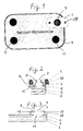
- the plate heat exchanger is a liquid-cooled oil cooler and consists of trough-shaped aluminum sheets 6 which are stacked one inside the other, so that 6 channels 5 for oil and for the cooling liquid are separated between the sheets.
- the channels 5 are connected in a manner not shown because they are known to the inlet and outlet channels 11 which are arranged in the cover plate 4 of the plate heat exchanger.
- Two channels 11 serve to supply and discharge the oil.
- the other two channels 11 are intended for the cooling liquid duct.
- the channel 11 arranged in the upper right corner of the plate heat exchanger has a connection.
- the other channels 11 are also equipped with connections (not shown). The connection is arranged relatively close to the edge of the plate heat exchanger, so that the flange 1 projects beyond the edge of the plate heat exchanger.
- connection has been punched out of an aluminum sheet. It has two through fastening openings 2 . A threaded insert 10 made of steel was inserted into each of these fastening bores 2 and fastened by caulking. The flange 1 has a flow opening 7 .
- the intermediate piece 3 was punched out of an aluminum sheet soldered on both sides and shaped like a pot by deep drawing. The bottom of the pot-like intermediate piece 3 has an opening which is surrounded by a collar 15 . This collar 15 fits exactly into the flow opening 7 of the flange 1 and was used there.
- the upper edge of the collar 15 has been folded outwards so that it bears positively on the edge of the flow opening 7 .
- Opposite the floor is the large opening of the pot-like intermediate piece 3 , which is also surrounded by an edge.
- the connection prefabricated as described so far is placed with the edge of the large opening of the intermediate piece 3 or the pot onto the channel 11 in the cover plate 4 of the plate heat exchanger and provisionally fixed in a suitable manner so that the position does not change until the completion of the soldering process can.
- Fig. 2 it can also be seen that there is a distance a between the flange 1 and the cover plate 4 , the size of which is determined by the dimensioning of the intermediate piece 3 . This made space available in which the threaded inserts 10 extend. It is therefore possible to select the thread inserts 10 suitable for the respective application, the same flange 1 always being able to be used.
- connection can be positioned as shown in FIG. 5. It is closer to the center of the plate heat exchanger than the connection from FIG. 1.
- the designs shown in FIG. 3 or 4 are suitable for such connection positions.
- two connections of the plate heat exchanger according to FIG. 2 could be formed and the other two according to the variants described below.
- only a single connection could be designed according to the invention and all other connections could be designed differently.
- the flange 1 is a deep-drawn part made of solder-coated aluminum sheet, with a border 33 and a folded edge on the border 33 .
- the flange 1 is placed over the channel 11 on the cover plate 4 and soldered as described.
- the flange 1 an about the shape of the flange 1 having Direction steel insert mechanically fixed with threaded holes 12 13 at the inside in such a way that the threaded holes 12 of the steel insert 13 and of course the flow opening 7 in the steel insert 13 with the corresponding openings 7; 8 in flange 1 match.
- the flange 1 is formed in one piece by deep drawing from the cover plate 4 . In this case, the steel insert 13 is inserted and fastened as described before the cover plate 4 is placed on the heat exchanger.
Landscapes
- Engineering & Computer Science (AREA)
- Physics & Mathematics (AREA)
- Thermal Sciences (AREA)
- Mechanical Engineering (AREA)
- General Engineering & Computer Science (AREA)
- Heat-Exchange Devices With Radiators And Conduit Assemblies (AREA)
- Details Of Heat-Exchange And Heat-Transfer (AREA)
Abstract
Description
Gewöhnlich sind Anschlußflansche Strangpreßteile, die, nach dem Abtrennen von dem gepreßten Strang, der etwa die Konturen des Anschlußflansches aufweist, mechanisch bearbeitet werden müssen. ( DE 196 54 362 A1) Die mechanische Bearbeitung ist relativ teuer, weshalb der gesamte Anschlußflansch oft das teuerste Einzelteil des Plattenwärmetauschers darstellt. Anschlußflansche werden auch als Druckgusserzeugnis, z.B. aus Aluminium, hergestellt, die jedoch ebenfalls kostenaufwendig sind und immer noch gewisse Schwierigkeiten bei der metallischen Verbindung, beispielsweise beim Löten, mit der Deck - oder Grundplatte verursachen. Anschlußflansche aus Aluminium benötigen eine vergleichsweise größere Dicke als solche aus Stahl, um die gleiche Haltbarkeit zu besitzen. Die DE 37 16 087 zeigt einen als Druckgusserzeugnis hergestellten Flansch. Ferner werden Anschlußflansche umformtechnisch als Stanzteil oder als Stanz - und Ziehteil hergestellt, die nach der löttechnischen Herstellung des Plattenwärmetauschers ebenfalls noch bearbeitet werden müssen.
Stanz - und Ziehteile sind insbesondere für Massenprodukte sehr kostengünstig herstellbar, wodurch die Kosten pro Anschluß um mehr als 60% gesenkt werden können. Die Ausbildung des Zwischenstücks als Stanz - und Ziehteil oder die am Flansch angeformte Umrandung erlauben den Einsatz dünnerer Deck und/oder Grundplatten. Als Massivblock ausgebildete bekannte Anschlußflansche erfordern für eine qualitätsgerechte Lötverbindung eine gewisse Mindestdicke der Deck - oder Grundplatte. Durch die Erfindung wird die Mindestdicke reduziert.
Die Ansprüche 2 bis 5 beziehen sich auf eine Variante, in der ein als Zwischenstück bezeichnetes Stanz - und Ziehteil und ein gestanzter Flansch verwendet wird, während die Ansprüche 6 und 7 eine alternative Ausführung des Anschlusses betreffen, in der auf das Zwischenstück verzichtet wird, weil der Flansch selbst als Tiefziehteil ausgeführt ist. Beide Anschlußvarianten könnten auch an ein und demselben Plattenwärmetauscher verwendet werden.
Anspruch 2 sieht vor, daß das Zwischenstück als Einzelteil mit dem als Stanzteil hergestellten Flansch verbunden und über einem Ein-oder Austrittskanal des Plattenwärmetauschers an der Grund-oder Deckplatte mittels Löten befestigt ist.
Der durch das Zwischenstück gebildete Abstand zwischen dem Flansch und der Deck - oder Grundplatte des Plattenwärmetauschers wird in der Form genutzt, daß sich die Gewindebuchsen in diesen Abstand hinein erstrecken. Dadurch kann die für die Haltbarkeit von Schraubverbindungen wichtige Gewindelänge entsprechend den geforderten Haltekräften variiert werden, indem Gewindebuchsen ausgewählt werden, die für den Einsatzfall optimal sind.
Das Zwischenstück soll in einer bevorzugten Variante ein beidseitig lotplattiertes Blechteil, insbesondere aus Aluminium sein. Dadurch wird erreicht, daß die Deck - oder Grundplatte des Plattenwärmetauschers an ihrer Außenseite nicht lotplattiert ausgeführt sein muß. Die äußere Lotplattierung an der Deck - oder Grundplatte hat sich in vielen Fällen als nachteilig herausgestellt, weil dort gewöhnlich Anlagepunkte der Lötvorrichtung vorhanden sind, die zu einer nicht gewünschten metallischen Verbindung zwischen der Lötvorrichtung und dem Plattenwärmetauscher führen.
Der erfindungsgemäße Anschluß besitzt insgesamt weniger Masse als ein massiver Flanschblock. Der Energieverbrauch beim Löten wird wesentlich von der zu verbindenden Gesamtmasse bestimmt.
Der erfindungsgemäße Anschluß wird vorgefertigt und als ein Teil mit der Deck - oder Grundplatte zusammengefügt. Dazu wird das Zwischenstück aus beidseitig lotplattiertem Blech ausgestanzt und zu einer topfartigen Gestalt mittels Tiefziehen geformt. Im Boden der topfartigen Gestalt befindet sich eine mit der Strömungsöffnung in dem Flansch korrelierende Öffnung, die von einem umlaufenden Kragen umgeben ist. Mit diesem Kragen wird das Zwischenstück in die Strömungsöffnung des Flansches gesteckt und durch Umformung des Kragens, insbesondere durch Umlegen des überstehenden Kragens nach außen, werden Flansch und Zwischenstück miteinander verbunden. Der Flansch kann bereits nach dem Ausstanzen, also vor dem Zusammenfügen mit dem Zwischenstück, mit den Gewindeeinsätzen versehen werden. Dabei werden die Gewindeeinsätze "provisorisch" beispielsweise durch Einnieten, Einpressen oder dergleichen in den Bohrungen der Flanschplatte befestigt. In der Massenproduktion können solche Anschlüsse nahezu vollautomatisch und deshalb kostengünstig hergestellt und angeboten werden.
Der wie beschrieben vorgefertigte Anschluß wird dann ebenfalls "provisorisch", d. h. zum Löten vorfixiert, über einem Ein - oder Ausströmkanal in der Deck - und/oder der Grundplatte befestigt. Anschließend wird der Plattenwärmetauscher in bekannter und hier nicht relevanter Weise unter Hinzufügung der mit Anschlüssen versehenen Grund - und/oder Deckplatte zusammengefügt, um danach als kompakter Block verlötet zu werden. Dabei wird sowohl die Lötverbindung zwischen dem Flansch und dem Zwischenstück, zwischen Gewindebuchse und Bohrung und zwischen Deck-und/oder Grundplatte und dem Zwischenstück hergestellt.
Die bereits erwähnte alternative Lösung sieht gemäß den Ansprüchen 6 und 7 vor, daß der Flansch mit der Umrandung entweder aus der Grund - oder Deckplatte oder als Einzelteil topfartig mittels Tiefziehen ausgeformt ist. Wenn der Flansch als Einzelteil hergestellt ist, ist an der Umrandung ein Rand oder dgl. angeformt. Mit diesem Rand wird der Flansch über einem Kanal in der Deck- oder Grundplatte angelötet.
Im Unterschied zu Fig. 3 wurde in Fig. 4 vorgesehen, daß der Flansch 1 einstückig mittels Tiefziehen aus der Deckplatte 4 ausgebildet ist. Der Stahleinsatz 13 wird in diesem Fall wie beschrieben eingesetzt und befestigt, bevor die Deckplatte 4 auf den Wärmetauscher aufgesetzt wird.
Claims (7)
- Anschluß für Plattenwärmetauscher, bestehend aus einem Flansch (1) mit mindestens einer Strömungsöffnung (7) und mit mehreren Bohrungen (8) an seiner einen Seite, zur Befestigung des Gegenflansches, wobei der Flansch (1) an seiner anderen Seite mit der Deck - oder Grundplatte (4) des Plattenwärmetauschers verbunden ist,
dadurch gekennzeichnet, daß
der Flansch (1) des Anschlusses ein Stanz -oder Tiefziehteil mit durchgehenden Befestigungsbohrungen (8) ist, der entweder über ein als Stanz - und Tiefziehteil ausgebildetes Zwischenstück (3) oder über eine am Flansch (1) mittels Tiefziehen angeformte Umrandung (33) mit der Deck - oder Grundplatte (4) des Plattenwärmetauschers verbunden ist. - Anschluß nach den Anspruch 1, dadurch gekennzeichnet, daß das Zwischenstück (3) als Einzelteil mit dem als Stanzteil hergestellten Flansch (1) verbunden und über einem Ein - oder Austrittskanal (11) des Plattenwärmetauschers an der Grund - oder Deckplatte (4) mittels Löten befestigt ist.
- Anschluß nach Anspruch 1 und 2, dadurch gekennzeichnet, daß der Flansch (1) aus Aluminium besteht und in den Befestigungsbohrungen (8) Gewindebuchsen (10) aus Stahl eingesetzt sind, die sich in den durch das Zwischenstück (3) gebildeten Abstand (a) zwischen dem Flansch (1) und der Deck - oder Grundplatte (4) des Plattenwärmetauschers hinein erstrecken.
- Anschluß nach einem der vorstehenden Ansprüche, dadurch gekennzeichnet, daß das Zwischenstück (3) aus beidseitig lotplattiertem Aluminiumblech besteht.
- Anschluß nach einem der vorstehenden Ansprüche, dadurch gekennzeichnet, daß das Zwischenstück (3) topfartig ausgebildet ist, mit einer Öffnung im Boden des Topfes, die von einem Kragen (15) umfaßt ist, wobei der Kragen (15) in die Strömungsöffnung (7) des Flansches (1) hineinpaßt, in der er verlötet ist und daß die gegenüber dem Boden angeordnete größere Öffnung einen Rand besitzt, mit dem das Zwischenstück auf der Grund - oder Deckplatte (4) verlötet ist.
- Anschluß nach Anspruch 1, dadurch gekennzeichnet, daß der Flansch (1) mit der Umrandung (33) entweder einstückig aus der Grund - oder Deckplatte (4) oder als Einzelteil topfartig mittels Tiefziehen ausgeformt ist.
- Anschluß nach den Ansprüchen 1 und 6, dadurch gekennzeichnet, daß ein Stahleinsatz (13) mit einer Strömungsöffnung (7) und mit Durchgangsöffnungen (12), in die ein Gewinde eingeformt ist, an der Unterseite des Flansches (1) in einer solchen Position angelötet und / oder mechanisch befestigt ist, daß die Befestigungsbohrungen (8) mit den Durchgangsöffnungen (12) und die Strömungsöffnungen (7) im Flansch (1) und im Stahleinsatz (13) übereinstimmen.
Applications Claiming Priority (2)
| Application Number | Priority Date | Filing Date | Title |
|---|---|---|---|
| DE10036583A DE10036583A1 (de) | 2000-07-27 | 2000-07-27 | Anschluß für Plattenwärmetauscher |
| DE10036583 | 2000-07-27 |
Publications (3)
| Publication Number | Publication Date |
|---|---|
| EP1176380A2 true EP1176380A2 (de) | 2002-01-30 |
| EP1176380A3 EP1176380A3 (de) | 2002-08-07 |
| EP1176380B1 EP1176380B1 (de) | 2004-03-03 |
Family
ID=7650394
Family Applications (1)
| Application Number | Title | Priority Date | Filing Date |
|---|---|---|---|
| EP01110663A Expired - Lifetime EP1176380B1 (de) | 2000-07-27 | 2001-05-02 | Plattenwärmetauscher mit einem Anschlussflansch |
Country Status (4)
| Country | Link |
|---|---|
| EP (1) | EP1176380B1 (de) |
| AT (1) | ATE261101T1 (de) |
| DE (2) | DE10036583A1 (de) |
| ES (1) | ES2217053T3 (de) |
Cited By (1)
| Publication number | Priority date | Publication date | Assignee | Title |
|---|---|---|---|---|
| EP1647796A1 (de) | 2004-10-14 | 2006-04-19 | Modine Manufacturing Company | Plattenwärmetauscher |
Citations (2)
| Publication number | Priority date | Publication date | Assignee | Title |
|---|---|---|---|---|
| DE3716087C1 (en) | 1987-05-14 | 1988-07-14 | Laengerer & Reich Kuehler | Method of making blind tapped holes in connecting flanges of heat exchangers |
| DE19654362A1 (de) | 1996-12-24 | 1998-06-25 | Behr Gmbh & Co | Wärmeübertrageranordnung |
Family Cites Families (8)
| Publication number | Priority date | Publication date | Assignee | Title |
|---|---|---|---|---|
| DE7134106U (de) * | 1972-02-10 | Schulz W | Anschweißflansch für Doppelmantel -Rohrleitungen | |
| DE2807444A1 (de) * | 1978-02-22 | 1979-08-23 | Schulz Wilhelm | Rohrleitungsflansch |
| DE2966553D1 (en) * | 1979-09-07 | 1984-02-23 | Wilhelm Schulz Apparate Und Ro | Flange |
| US4872578A (en) * | 1988-06-20 | 1989-10-10 | Itt Standard Of Itt Corporation | Plate type heat exchanger |
| JPH0818124B2 (ja) * | 1992-05-22 | 1996-02-28 | 昭和アルミニウム株式会社 | 熱交換器 |
| DE4314808C2 (de) * | 1993-05-05 | 2003-10-30 | Behr Gmbh & Co | Plattenwärmetauscher, insbesondere Öl/Kühlmittel-Kühler |
| DE19628561C1 (de) * | 1996-07-16 | 1997-09-04 | Laengerer & Reich Gmbh & Co | Plattenwärmetauscher |
| SE9702420L (sv) * | 1997-06-25 | 1998-12-26 | Alfa Laval Ab | Plattvärmeväxlare |
-
2000
- 2000-07-27 DE DE10036583A patent/DE10036583A1/de not_active Withdrawn
-
2001
- 2001-05-02 ES ES01110663T patent/ES2217053T3/es not_active Expired - Lifetime
- 2001-05-02 AT AT01110663T patent/ATE261101T1/de not_active IP Right Cessation
- 2001-05-02 EP EP01110663A patent/EP1176380B1/de not_active Expired - Lifetime
- 2001-05-02 DE DE50101583T patent/DE50101583D1/de not_active Expired - Fee Related
Patent Citations (2)
| Publication number | Priority date | Publication date | Assignee | Title |
|---|---|---|---|---|
| DE3716087C1 (en) | 1987-05-14 | 1988-07-14 | Laengerer & Reich Kuehler | Method of making blind tapped holes in connecting flanges of heat exchangers |
| DE19654362A1 (de) | 1996-12-24 | 1998-06-25 | Behr Gmbh & Co | Wärmeübertrageranordnung |
Cited By (1)
| Publication number | Priority date | Publication date | Assignee | Title |
|---|---|---|---|---|
| EP1647796A1 (de) | 2004-10-14 | 2006-04-19 | Modine Manufacturing Company | Plattenwärmetauscher |
Also Published As
| Publication number | Publication date |
|---|---|
| EP1176380A3 (de) | 2002-08-07 |
| DE50101583D1 (de) | 2004-04-08 |
| EP1176380B1 (de) | 2004-03-03 |
| DE10036583A1 (de) | 2002-02-07 |
| ES2217053T3 (es) | 2004-11-01 |
| ATE261101T1 (de) | 2004-03-15 |
Similar Documents
| Publication | Publication Date | Title |
|---|---|---|
| DE10347181B4 (de) | Wärmetauscher, insbesondere Ölkühler | |
| EP0828980B1 (de) | Wärmetauscher | |
| DE69400127T2 (de) | Wärmeaustauscher für elektronische Bauteile und elektrische Apparate | |
| EP2454547B1 (de) | Plattenwärmetauscher mit mehreren übereinander gestapelten platten | |
| EP1452816B1 (de) | Plattenwärmetauscher | |
| DE19802012C2 (de) | Gehäuseloser Plattenwärmetauscher | |
| EP1306638B1 (de) | Gehäuseloser Plattenwärmetauscher | |
| DE19805439B4 (de) | Verfahren zur Herstellung eines Stapelscheibenwärmeübertragers und dadurch hergestellter Wärmeübertrager | |
| DE102020207947A1 (de) | Kühlanordnung für elektronische Komponenten eines Kraftfahrzeugs und Herstellungsverfahren dafür | |
| EP1855074A2 (de) | Wärmetauscher, insbesondere Ölkühler | |
| DE102007030563A1 (de) | Plattenwärmetauscher und Montageverfahren | |
| DE19611447C1 (de) | Gehäuseloser Plattenwärmetauscher | |
| DE60004295T2 (de) | Plattenwärmetauscher, insbesondere zum Kühlen von Kraftfahrzeugöl | |
| EP2154465B1 (de) | Plattenwärmetauscher | |
| DE20121112U1 (de) | Sammelkasten für einen Wärmeaustauscher, insbesondere an Kraftfahrzeugen | |
| EP1176380B1 (de) | Plattenwärmetauscher mit einem Anschlussflansch | |
| EP0819906B1 (de) | Anschlussadapter für Plattenwärmetauscher | |
| DE9400502U1 (de) | Wärmetauscher, insbesondere Kältemittelverdampfer | |
| EP1861877B1 (de) | Vorrichtung zur Kühlung von elektronischen Bauteilen | |
| DE10212801C1 (de) | Kühler für flüssige Medien sowie Verfahren zur Herstellung eines solchen Kühlers | |
| DE29611633U1 (de) | Wärmeaustauscher | |
| EP0893667A2 (de) | Gehäuseloser Plattenwärmetauscher | |
| DE10307425A1 (de) | Gebläseluft-Kühlkörper | |
| EP1083128A1 (de) | Behälter | |
| DE20205202U1 (de) | Kühler für flüssige Medien |
Legal Events
| Date | Code | Title | Description |
|---|---|---|---|
| PUAI | Public reference made under article 153(3) epc to a published international application that has entered the european phase |
Free format text: ORIGINAL CODE: 0009012 |
|
| AK | Designated contracting states |
Kind code of ref document: A2 Designated state(s): AT BE CH CY DE DK ES FI FR GB GR IE IT LI LU MC NL PT SE TR |
|
| AX | Request for extension of the european patent |
Free format text: AL;LT;LV;MK;RO;SI |
|
| PUAL | Search report despatched |
Free format text: ORIGINAL CODE: 0009013 |
|
| AK | Designated contracting states |
Kind code of ref document: A3 Designated state(s): AT BE CH CY DE DK ES FI FR GB GR IE IT LI LU MC NL PT SE TR |
|
| AX | Request for extension of the european patent |
Free format text: AL;LT;LV;MK;RO;SI |
|
| 17P | Request for examination filed |
Effective date: 20030207 |
|
| AKX | Designation fees paid |
Designated state(s): AT BE CH CY DE DK ES FI FR GB GR IE IT LI LU MC NL PT SE TR |
|
| 17Q | First examination report despatched |
Effective date: 20030407 |
|
| GRAP | Despatch of communication of intention to grant a patent |
Free format text: ORIGINAL CODE: EPIDOSNIGR1 |
|
| RTI1 | Title (correction) |
Free format text: PLATE HEAT EXCHANGER WITH CONNECTING FLANGE |
|
| GRAS | Grant fee paid |
Free format text: ORIGINAL CODE: EPIDOSNIGR3 |
|
| GRAA | (expected) grant |
Free format text: ORIGINAL CODE: 0009210 |
|
| AK | Designated contracting states |
Kind code of ref document: B1 Designated state(s): AT BE CH CY DE DK ES FI FR GB GR IE IT LI LU MC NL PT SE TR |
|
| PG25 | Lapsed in a contracting state [announced via postgrant information from national office to epo] |
Ref country code: TR Free format text: LAPSE BECAUSE OF FAILURE TO SUBMIT A TRANSLATION OF THE DESCRIPTION OR TO PAY THE FEE WITHIN THE PRESCRIBED TIME-LIMIT Effective date: 20040303 Ref country code: NL Free format text: LAPSE BECAUSE OF FAILURE TO SUBMIT A TRANSLATION OF THE DESCRIPTION OR TO PAY THE FEE WITHIN THE PRESCRIBED TIME-LIMIT Effective date: 20040303 Ref country code: FI Free format text: LAPSE BECAUSE OF FAILURE TO SUBMIT A TRANSLATION OF THE DESCRIPTION OR TO PAY THE FEE WITHIN THE PRESCRIBED TIME-LIMIT Effective date: 20040303 Ref country code: CY Free format text: LAPSE BECAUSE OF FAILURE TO SUBMIT A TRANSLATION OF THE DESCRIPTION OR TO PAY THE FEE WITHIN THE PRESCRIBED TIME-LIMIT Effective date: 20040303 Ref country code: IE Free format text: LAPSE BECAUSE OF FAILURE TO SUBMIT A TRANSLATION OF THE DESCRIPTION OR TO PAY THE FEE WITHIN THE PRESCRIBED TIME-LIMIT Effective date: 20040303 |
|
| REG | Reference to a national code |
Ref country code: GB Ref legal event code: FG4D Free format text: NOT ENGLISH |
|
| REG | Reference to a national code |
Ref country code: CH Ref legal event code: EP |
|
| REG | Reference to a national code |
Ref country code: IE Ref legal event code: FG4D Free format text: GERMAN |
|
| REF | Corresponds to: |
Ref document number: 50101583 Country of ref document: DE Date of ref document: 20040408 Kind code of ref document: P |
|
| PG25 | Lapsed in a contracting state [announced via postgrant information from national office to epo] |
Ref country code: AT Free format text: LAPSE BECAUSE OF NON-PAYMENT OF DUE FEES Effective date: 20040502 Ref country code: LU Free format text: LAPSE BECAUSE OF NON-PAYMENT OF DUE FEES Effective date: 20040502 |
|
| PG25 | Lapsed in a contracting state [announced via postgrant information from national office to epo] |
Ref country code: MC Free format text: LAPSE BECAUSE OF NON-PAYMENT OF DUE FEES Effective date: 20040531 Ref country code: BE Free format text: LAPSE BECAUSE OF NON-PAYMENT OF DUE FEES Effective date: 20040531 |
|
| PG25 | Lapsed in a contracting state [announced via postgrant information from national office to epo] |
Ref country code: DK Free format text: LAPSE BECAUSE OF FAILURE TO SUBMIT A TRANSLATION OF THE DESCRIPTION OR TO PAY THE FEE WITHIN THE PRESCRIBED TIME-LIMIT Effective date: 20040603 Ref country code: GR Free format text: LAPSE BECAUSE OF FAILURE TO SUBMIT A TRANSLATION OF THE DESCRIPTION OR TO PAY THE FEE WITHIN THE PRESCRIBED TIME-LIMIT Effective date: 20040603 |
|
| REG | Reference to a national code |
Ref country code: SE Ref legal event code: TRGR |
|
| GBT | Gb: translation of ep patent filed (gb section 77(6)(a)/1977) |
Effective date: 20040527 |
|
| NLV1 | Nl: lapsed or annulled due to failure to fulfill the requirements of art. 29p and 29m of the patents act | ||
| REG | Reference to a national code |
Ref country code: IE Ref legal event code: FD4D |
|
| REG | Reference to a national code |
Ref country code: ES Ref legal event code: FG2A Ref document number: 2217053 Country of ref document: ES Kind code of ref document: T3 |
|
| BERE | Be: lapsed |
Owner name: MODINE MANUFACTURING CY Effective date: 20040531 |
|
| ET | Fr: translation filed | ||
| PLBE | No opposition filed within time limit |
Free format text: ORIGINAL CODE: 0009261 |
|
| STAA | Information on the status of an ep patent application or granted ep patent |
Free format text: STATUS: NO OPPOSITION FILED WITHIN TIME LIMIT |
|
| 26N | No opposition filed |
Effective date: 20041206 |
|
| PG25 | Lapsed in a contracting state [announced via postgrant information from national office to epo] |
Ref country code: LI Free format text: LAPSE BECAUSE OF NON-PAYMENT OF DUE FEES Effective date: 20050531 Ref country code: CH Free format text: LAPSE BECAUSE OF NON-PAYMENT OF DUE FEES Effective date: 20050531 |
|
| REG | Reference to a national code |
Ref country code: CH Ref legal event code: PL |
|
| PGFP | Annual fee paid to national office [announced via postgrant information from national office to epo] |
Ref country code: ES Payment date: 20070518 Year of fee payment: 7 |
|
| PGFP | Annual fee paid to national office [announced via postgrant information from national office to epo] |
Ref country code: SE Payment date: 20070521 Year of fee payment: 7 |
|
| PGFP | Annual fee paid to national office [announced via postgrant information from national office to epo] |
Ref country code: DE Payment date: 20070629 Year of fee payment: 7 |
|
| PGFP | Annual fee paid to national office [announced via postgrant information from national office to epo] |
Ref country code: GB Payment date: 20070419 Year of fee payment: 7 |
|
| PG25 | Lapsed in a contracting state [announced via postgrant information from national office to epo] |
Ref country code: PT Free format text: LAPSE BECAUSE OF NON-PAYMENT OF DUE FEES Effective date: 20040803 |
|
| PGFP | Annual fee paid to national office [announced via postgrant information from national office to epo] |
Ref country code: IT Payment date: 20070524 Year of fee payment: 7 |
|
| PGFP | Annual fee paid to national office [announced via postgrant information from national office to epo] |
Ref country code: FR Payment date: 20070518 Year of fee payment: 7 |
|
| GBPC | Gb: european patent ceased through non-payment of renewal fee |
Effective date: 20080502 |
|
| REG | Reference to a national code |
Ref country code: FR Ref legal event code: ST Effective date: 20090119 |
|
| PG25 | Lapsed in a contracting state [announced via postgrant information from national office to epo] |
Ref country code: FR Free format text: LAPSE BECAUSE OF NON-PAYMENT OF DUE FEES Effective date: 20080602 Ref country code: DE Free format text: LAPSE BECAUSE OF NON-PAYMENT OF DUE FEES Effective date: 20081202 |
|
| PG25 | Lapsed in a contracting state [announced via postgrant information from national office to epo] |
Ref country code: GB Free format text: LAPSE BECAUSE OF NON-PAYMENT OF DUE FEES Effective date: 20080502 |
|
| REG | Reference to a national code |
Ref country code: ES Ref legal event code: FD2A Effective date: 20080503 |
|
| PG25 | Lapsed in a contracting state [announced via postgrant information from national office to epo] |
Ref country code: IT Free format text: LAPSE BECAUSE OF NON-PAYMENT OF DUE FEES Effective date: 20080502 |
|
| PG25 | Lapsed in a contracting state [announced via postgrant information from national office to epo] |
Ref country code: ES Free format text: LAPSE BECAUSE OF NON-PAYMENT OF DUE FEES Effective date: 20080503 |
|
| PG25 | Lapsed in a contracting state [announced via postgrant information from national office to epo] |
Ref country code: SE Free format text: LAPSE BECAUSE OF NON-PAYMENT OF DUE FEES Effective date: 20080503 |