EP1176018B1 - Verfahren zum Ausstossen von Flüssigkeit - Google Patents
Verfahren zum Ausstossen von Flüssigkeit Download PDFInfo
- Publication number
- EP1176018B1 EP1176018B1 EP01118120A EP01118120A EP1176018B1 EP 1176018 B1 EP1176018 B1 EP 1176018B1 EP 01118120 A EP01118120 A EP 01118120A EP 01118120 A EP01118120 A EP 01118120A EP 1176018 B1 EP1176018 B1 EP 1176018B1
- Authority
- EP
- European Patent Office
- Prior art keywords
- liquid
- discharge
- bubble
- discharged
- movable member
- Prior art date
- Legal status (The legal status is an assumption and is not a legal conclusion. Google has not performed a legal analysis and makes no representation as to the accuracy of the status listed.)
- Expired - Lifetime
Links
Images


Classifications
-
- B—PERFORMING OPERATIONS; TRANSPORTING
- B41—PRINTING; LINING MACHINES; TYPEWRITERS; STAMPS
- B41J—TYPEWRITERS; SELECTIVE PRINTING MECHANISMS, i.e. MECHANISMS PRINTING OTHERWISE THAN FROM A FORME; CORRECTION OF TYPOGRAPHICAL ERRORS
- B41J2/00—Typewriters or selective printing mechanisms characterised by the printing or marking process for which they are designed
- B41J2/005—Typewriters or selective printing mechanisms characterised by the printing or marking process for which they are designed characterised by bringing liquid or particles selectively into contact with a printing material
- B41J2/01—Ink jet
- B41J2/015—Ink jet characterised by the jet generation process
- B41J2/04—Ink jet characterised by the jet generation process generating single droplets or particles on demand
- B41J2/045—Ink jet characterised by the jet generation process generating single droplets or particles on demand by pressure, e.g. electromechanical transducers
- B41J2/04501—Control methods or devices therefor, e.g. driver circuits, control circuits
- B41J2/0458—Control methods or devices therefor, e.g. driver circuits, control circuits controlling heads based on heating elements forming bubbles
-
- B—PERFORMING OPERATIONS; TRANSPORTING
- B41—PRINTING; LINING MACHINES; TYPEWRITERS; STAMPS
- B41J—TYPEWRITERS; SELECTIVE PRINTING MECHANISMS, i.e. MECHANISMS PRINTING OTHERWISE THAN FROM A FORME; CORRECTION OF TYPOGRAPHICAL ERRORS
- B41J2/00—Typewriters or selective printing mechanisms characterised by the printing or marking process for which they are designed
- B41J2/005—Typewriters or selective printing mechanisms characterised by the printing or marking process for which they are designed characterised by bringing liquid or particles selectively into contact with a printing material
- B41J2/01—Ink jet
- B41J2/015—Ink jet characterised by the jet generation process
- B41J2/04—Ink jet characterised by the jet generation process generating single droplets or particles on demand
- B41J2/045—Ink jet characterised by the jet generation process generating single droplets or particles on demand by pressure, e.g. electromechanical transducers
- B41J2/04501—Control methods or devices therefor, e.g. driver circuits, control circuits
- B41J2/04588—Control methods or devices therefor, e.g. driver circuits, control circuits using a specific waveform
-
- B—PERFORMING OPERATIONS; TRANSPORTING
- B41—PRINTING; LINING MACHINES; TYPEWRITERS; STAMPS
- B41J—TYPEWRITERS; SELECTIVE PRINTING MECHANISMS, i.e. MECHANISMS PRINTING OTHERWISE THAN FROM A FORME; CORRECTION OF TYPOGRAPHICAL ERRORS
- B41J2/00—Typewriters or selective printing mechanisms characterised by the printing or marking process for which they are designed
- B41J2/005—Typewriters or selective printing mechanisms characterised by the printing or marking process for which they are designed characterised by bringing liquid or particles selectively into contact with a printing material
- B41J2/01—Ink jet
- B41J2/015—Ink jet characterised by the jet generation process
- B41J2/04—Ink jet characterised by the jet generation process generating single droplets or particles on demand
- B41J2/045—Ink jet characterised by the jet generation process generating single droplets or particles on demand by pressure, e.g. electromechanical transducers
- B41J2/04501—Control methods or devices therefor, e.g. driver circuits, control circuits
- B41J2/04591—Width of the driving signal being adjusted
-
- B—PERFORMING OPERATIONS; TRANSPORTING
- B41—PRINTING; LINING MACHINES; TYPEWRITERS; STAMPS
- B41J—TYPEWRITERS; SELECTIVE PRINTING MECHANISMS, i.e. MECHANISMS PRINTING OTHERWISE THAN FROM A FORME; CORRECTION OF TYPOGRAPHICAL ERRORS
- B41J2/00—Typewriters or selective printing mechanisms characterised by the printing or marking process for which they are designed
- B41J2/005—Typewriters or selective printing mechanisms characterised by the printing or marking process for which they are designed characterised by bringing liquid or particles selectively into contact with a printing material
- B41J2/01—Ink jet
- B41J2/015—Ink jet characterised by the jet generation process
- B41J2/04—Ink jet characterised by the jet generation process generating single droplets or particles on demand
- B41J2/045—Ink jet characterised by the jet generation process generating single droplets or particles on demand by pressure, e.g. electromechanical transducers
- B41J2/04501—Control methods or devices therefor, e.g. driver circuits, control circuits
- B41J2/04598—Pre-pulse
-
- B—PERFORMING OPERATIONS; TRANSPORTING
- B41—PRINTING; LINING MACHINES; TYPEWRITERS; STAMPS
- B41J—TYPEWRITERS; SELECTIVE PRINTING MECHANISMS, i.e. MECHANISMS PRINTING OTHERWISE THAN FROM A FORME; CORRECTION OF TYPOGRAPHICAL ERRORS
- B41J2/00—Typewriters or selective printing mechanisms characterised by the printing or marking process for which they are designed
- B41J2/005—Typewriters or selective printing mechanisms characterised by the printing or marking process for which they are designed characterised by bringing liquid or particles selectively into contact with a printing material
- B41J2/01—Ink jet
- B41J2/135—Nozzles
- B41J2/14—Structure thereof only for on-demand ink jet heads
- B41J2/14016—Structure of bubble jet print heads
- B41J2/14032—Structure of the pressure chamber
- B41J2/14048—Movable member in the chamber
-
- B—PERFORMING OPERATIONS; TRANSPORTING
- B41—PRINTING; LINING MACHINES; TYPEWRITERS; STAMPS
- B41J—TYPEWRITERS; SELECTIVE PRINTING MECHANISMS, i.e. MECHANISMS PRINTING OTHERWISE THAN FROM A FORME; CORRECTION OF TYPOGRAPHICAL ERRORS
- B41J2202/00—Embodiments of or processes related to ink-jet or thermal heads
- B41J2202/01—Embodiments of or processes related to ink-jet heads
- B41J2202/06—Heads merging droplets coming from the same nozzle
Definitions
- the present invention relates to a method for discharging liquide according to the preamble of claim 1 to discharge desired liquid by generating bubbles by applying thermal energy to liquid.
- the present invention is applicable to an apparatus such as a printer to execute recording on a recording medium to be recorded, such as paper, thread, fiber, fabric, leather, metal, plastic, glass, lumber, ceramics, a photocopier, a facsimile having transmission system, and a word processor having a printer part and the like and moreover to an industrial recording apparatus that was mixed in a complex fashion with various processing devices.
- a recording medium to be recorded such as paper, thread, fiber, fabric, leather, metal, plastic, glass, lumber, ceramics, a photocopier, a facsimile having transmission system, and a word processor having a printer part and the like and moreover to an industrial recording apparatus that was mixed in a complex fashion with various processing devices.
- the term "recording" in the present invention means not only to give images having meanings such as letters and drawings etc. to a recording medium to be recorded but also means to give images not having meanings such as patterns etc.
- Liquid jet recording method or so-called bubble jet recording method, that gives energy such as heat to ink (liquid) to cause liquid to undergo status change accompanying precipitous volume change (generation of bubbles) and discharges liquid from a discharge port with application force based on this status change, causes this to attach onto a recording medium to be recorded, and proceeds with image forming, is conventionally known.
- a discharge port to discharge liquid, a liquid flow path to communicate with this discharge port, and an electro-heat converter as energy generating means for discharging liquid disposed inside the liquid flow path are generally disposed.
- Such a recording method enables to record high dignity images at a high speed and with low noises, and can dispose the discharge port to discharge liquid at a high density in the head to execute this recording method, and therefore has a lot of excellent advantages so as to easily obtain recorded images and moreover color images as well with high resolution with a small apparatus. Therefore, this bubble jet recording method is recently utilized for a lot of office apparatus such as a printer, a photocopier and a facsimile etc. and moreover has become utilized even for systems for industrial use such as a textile printing apparatus etc.
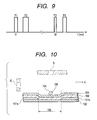
- FIG. 10 Schematic section view around an electro-heat converter of liquid discharge head of a prior art example to execute recording by such a recording method is shown in FIG. 10.
- the electro-heat converter is constructed by a resistant layer 100 and electrodes 101a and 101b laminated thereon and formed as a pair having a gap. That is, the heat generating part 105 to generate heat by applying voltages is formed between the electrode 101a and the electrode 101b, and this part will become a bubble generation region where bubbles are formed by film boiling.
- two layers of protection layers 102 and 103 protecting these are formed further.
- the discharge port to discharge liquid by generating a bubble 104 with heat generation at the heat-generating body 105 is disposed at a position facing the heat-generating body 105 such as the discharge port S (so-called side shooter type) or is disposed at the side direction such as the discharge port E (so-called edge shooter type).
- the bubble 104 grows comparatively large toward the liquid chamber side X with comparatively small flow path resistant, and therefore the bubble disappearance position 106 is likely to come to the center area of the heat-generating body 105 or a little bit biased to the direction of the liquid chamber side.
- a liquid discharge head known is the one having a construction that comprises a movable member to undergo displacement provided in the bubble generating region and accompanied by growth of bubbles and a controller to control the displacement of the movable member within a desired range, and the controller is provided to face the bubble generating region of the liquid flow path so that substantial contact between the movable member having undergone displacement and the controller will constitute a substantially closed space except the discharge port.
- the controller is provided to face the bubble generating region of the liquid flow path so that substantial contact between the movable member having undergone displacement and the controller will constitute a substantially closed space except the discharge port.
- the movable member undergoes displacement so as to make the flow resistant at the upstream side small, and bubble disappearance at the upstream side of the bubble generation region is promoted to occur ahead than at the downstream side. Therefore, retreat quantity of meniscus is small and refill of liquid is executed efficiently.
- the gas having melted into the liquid is released at the time when bubbles are formed, giving rise to a case where microbubbles are formed and remain behind.
- the liquid in the vicinity of the discharge port is sucked out so that recovery operation such as removal of microbubbles is executed on a regular basis.
- the liquid discharge head comprising the movable member the liquid is never pushed back to the upstream side, and therefore the microbubbles are released from the discharge port before increasing in number enough to cause troubles in the discharge operation, and hardly remain behind. Therefore, over a comparatively long period, consecutive recording can be executed and for the maximum, it is possible to execute recording of 100 sheets or more in a consecutive manner.
- the liquid discharge head comprising a movable member has an advantage that it can execute refilling of liquid swiftly without giving rise to considerable retreat of the meniscus, and therefore at a comparatively short time interval, discharge of liquid can be executed, and driving with a comparatively high frequency is possible.
- a generic method for discharging liquid is known from EP-A-0 982 136 . It comprises a step of heating a liquid filling a liquid flow path with a heat-generating body to generate bubble in the liquid, and a step of discharging the liquid from a discharge port communicating with the liquid flow path using energy produced in the bubble generation. The steps are repeated plural times to discharge a plurality of liquid droplets in a consecutive manner.
- the discharged liquid droplets following the preceding discharged liquid droplets being made capable of capturing the satellite can be obtained for the first time by executing liquid discharge in a continuous fashion at an extremely short interval with the method for discharging liquid of the present invention.
- the method for discharging liquid of the present invention can be said to be a method for discharging liquid having a step to heat liquid filled in inside the liquid path with a heat-generating body to generate bubbles in the liquid and a step to discharge liquid with energy at the time when the bubbles are given rise to from the discharge port that communicates to the liquid path to form discharged liquid droplets to be discharged and to discharge a plurality of discharged liquid droplets in a continuous fashion by repeating these steps a plurality of times, wherein the discharged liquid droplets discharged by the succeeding liquid discharge captures satellites while the satellites keep their shape being liquid pillars, and this discharged liquid droplet and the satellite are integrated.
- the satellite will become approximately spherical with surface tension during flying steps, but in the method for dis
- the arrangement to make the energy to be supplied to the heat-generating body at the liquid discharge of the consecutive discharge for the second time and onwards smaller than that for the first time can be executed in particular by making a pulse width of a voltage pulse to be applied to the heat-generating body at the liquid discharge for the second time smaller than that for the first time.
- the heat generating body is not driven for the next discharge after the end of disappearance of a bubble formed at the time of the preceding liquid discharge, but is to execute discharge continuously at a timing by taking the balance between the succeeding bubble formation for discharge and the discharge, utilizing bubbles formed by the preceding liquid discharge, which is an epoch-making invention.
- the present invention has been realized by finding out from the relationship between the bubble changes and the position of the meniscus that there is a timing enabling discharge of liquid well prior to the end of bubble disappearance at the time of preceding liquid discharge.
- the liquid discharge head comprising the movable member will present such a state that bubbles which have been formed due to the preceding liquid discharge but are on the verge of disappearance exist at the discharge port side of the bubble generation region and that bubbles do not exist at the position closer to the liquid chamber.
- retreat of the meniscus has started but has not reached maximum.
- replenishment of the liquid has been substantially completed, and is in a sufficient refilling state.
- the liquid discharge head is in an extremely advantageous state for executing the next discharge, and the driving energy for the next liquid discharge is supplied to the heat-generating body at this timing so that a consecutive liquid discharge can be executed well.
- Execution of liquid consecutive discharge at this timing means consecutive execution of liquid in an extremely short interval compared with the case where the next liquid discharge is executed after completion of bubble disappearance as in the prior arts.
- the driving energy for liquid discharge continued under a state that a part of bubbles having been formed at the time of the preceding liquid discharge have remained at the downstream side is supplied to the heat-generating body, the liquid flow from the upstream side that is accompanied by disappearance of the bubbles having remained at the downstream side affects at the time of the liquid discharge for the second shot and onwards. This serves to improve energy efficiency of the liquid discharge for the succeeding liquid discharge.
- action of liquid flow from the upstream side can enlarge the volume of the discharged liquid droplet to be discharged at the time of liquid discharge for the second shot and onwards than the volume of the discharged liquid droplet when the liquid discharge is executed from the normal state.
- the liquid flow from the upstream side can accelerate the flow of the liquid at the time of the succeeding liquid discharge, and can make the speed of the discharged liquid droplets at the time of liquid discharge for the second shot and onwards faster than the speed of the discharged liquid droplets at the time when the liquid discharge has been executed from the normal state.
- the volume of consecutive discharged liquid droplets being made larger and the speed thereof being made faster than those at the normal time will give advantages that they are convenient for proceeding with multi-gradation recording.
- liquid discharge can be executed in a continuous fashion at an extremely short interval.
- the part tailing backward of the discharged liquid droplet is separated to form the satellite, which can be arranged to be captured by the discharged liquid droplets at the succeeding liquid discharge.
- the succeeding discharge liquid droplets being made capable of capturing the sattelite will give advantage that they are convenient for proceeding with multi-gradation recording.
- Fig. 1 is a side sectional schematic view of a key part of a liquid discharge head to be used for liquid discharge of an embodiment of the present invention.
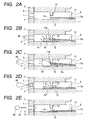
- Figs. 2A to 2F are explanatory views describing liquid discharge procedure for a single session on the liquid from the liquid discharge head having been shown in Fig. 1.
- This liquid discharge head has an element substrate 1 having a heat-generating body 10 being bubble generation means and a movable member 11, a ceiling plate 2 where a stopper (controller) 12 has been formed and an orifice plate 5 where a discharge port 4 has been formed.
- the flow path (liquid flow path) 3 where liquid flows is formed fixing the element substrate 1 and the ceiling plate 2 under a laminated state.
- the flow path 3 is formed in plurality in parallel for one liquid discharge head, and communicates with the discharge port 4 formed in the downstream side (left side in Fig. 1) to discharge liquid.
- a bubble generation region exists in the region in the vicinity of a face where the heat-generating body 10 and the liquid are brought into contact.
- a common liquid chamber 6 with a large volume is provided so as to communicate simultaneously to the upstream side (the right side in Fig. 1) of these respective flow paths 3. That is, the respective flow paths 3 are shaped to be branched off from a single common liquid chamber 6.
- the height of the liquid chamber of this common liquid chamber 6 is formed higher than the height of the flow path of the flow path 3.
- the movable member 11 is like a cantilever to support at one end, and is fixed to the element substrate 1 in the upstream side of the stream of the ink (liquid), and the downstream portion lower than the pivot point 11a is movable upward and downward toward the element substrate 1.
- the movable member 11 is disposed approximately in parallel along the element substrate 1 while holding a gap toward the element substrate 1 in the initial state.
- the movable member 11 disposed in the element substrate 1 has a free end 11b being disposed so as to be positioned approximately in the central region of the heat-generating body 10.
- the stopper 12 provided in the ceiling plate 2 is to control the displacement quantity of the free end 11b to upward by the free end 11b of the movable member 11 contacting the stopper 12.
- the flow path 3 will be substantially cut off by the movable member 11 and the stopper 12 into the upstream portion of the movable member 11 and the stopper 12 and the downstream portion of the movable member 11 and the stopper 12.
- the position Y of the free end 11b and the end X of the stopper 12 are disposed on the face perpendicular to the element substrate 1. Moreover, further preferably it is preferable that these X and Y together with Z being the center of the heat-generating body 10 are disposed on a face perpendicular to the substrate.
- the height of the flow path 3 at the downstream side from the stopper 12 will be shaped to rise steeply.
- the bubbles at the downstream side of the bubble generation region has sufficient height also when the movable member 11 is controlled by the stopper 12, and therefore, since the growth of bubbles are not hindered, the liquid can be orientated toward the discharge port 4 smoothly and unevenness in pressure balance in the direction of height from the lower end to the upper end of the discharge port 4 gets less, good liquid discharge can be executed.
- the ceiling shape at the side of the common liquid chamber 6 has been arranged to rise up steeply.
- this construction lacks the movable member 11, the fluid resistant in the downstream side of the bubble generation region gets smaller than the fluid resistant at the upstream side, and thus the pressure to be used for discharge was not apt to be applied to the side of the discharge port 4, but in the present embodiment, movement of bubbles to the upstream side of bubble generation region is substantially cut off with the movable member 11 when the bubbles are formed, and therefore the pressure to be used for discharge actively goes toward the side of the discharge port 4, and when the liquid is supplied, the fluid resistant at the upstream side of the bubble generation region will get less so that liquid supply to the bubble generation region is arranged to be executed rapidly.
- the growth component to the downstream side and the growth component to the downstream side of the bubbles are not uniform so that the growth component to the upstream side gets less to control movement of the liquid to the upstream side. Since the flow of liquid to the upstream side is controlled, the retreat quantity of the meniscus after discharge gets less and in turn for that portion surpassing quantity (overshoot quantity) of the meniscus than the orifice surface (liquid discharge face) 5a will be decreased. Accordingly, the meniscus vibration will be controlled so that stable discharge is executed over all kinds of driving frequencies from the low frequency to the high frequency.
- the path between the part at the downstream side of the bubbles and the discharge port 4 maintains straight flow path structure toward the liquid flow or "linear communication state".
- throwing power of bubbles to the upper face of the above described movable member has been studied to give rise to a knowledge that relationship between the movement velocity of the movable member and the bubble growth velocity (in other words movement velocity of the liquid) cancels the throwing power of bubbles to the upper face of the movable member so as to make good discharge performance available.
- control of the movable member by way of controller is arranged to be executed at a stage that the displacement of the movable member approximately follows the movement of the liquid.
- the displacement velocity of the movable member as well as the growth velocity of the bubbles (the movement velocity of the liquid) will be expressed and referred to as "movable member displacement volume change” and "bubble volume change”.
- this "movable member displacement volume change” and “bubble volume change” are given by differentiating the movable member displacement volume and the bubble volume.
- the distance (the protruding height of the stopper 12) between the part of the stopper 12 and the face (upper wall face) opposite the substrate 1 of the flow path 3 is desirably provided sufficiently.
- control of displacement of the movable member by the controller refers to a state that displacement volume change of the movable member gives 0 or a negative value.
- the height of the flow path 3 is 55 ⁇ m, thickness of the movable member 11 is 5 ⁇ m and clearance between the lower face of the movable member 11 and the upper face of the element substrate 1 is 5 ⁇ m under the state that the bubbles have not been generated (a state that the movable member 11 has not been displaced).
- t 1 is not less than 30 ⁇ m
- t 2 should be not more than 15 ⁇ m so that the liquid can enhance a stable discharge performance and with t1 being not less than 20 ⁇ m, t 2 should preferably be not more than 25 ⁇ m.
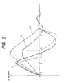
- Figs. 2A to 2E and Fig. 3 being a graph showing chronological changes between the displacement velocity and the volume of the bubbles and chronological changes between the displacement velocity and the volume of the movable member.
- the bubble volume change v b is expressed by a full line, the bubble volume V b by a two-dotted chained line, the movable member displacement volume change v m by a broken line and the movable member displacement volume change V m by single-doted chained line respectively.
- increase in the bubble volume V b is expressed as positive
- increase in volume is expressed as positive
- increase in the movable member displacement volume change V m is expressed as positive
- increase in volume is expressed as positive respectively.
- the movable member displacement volume change V m treats the volume as positive when the movable member 11 undergoes displacement from the initial state in Fig. 2A to the side of the ceiling plate 2, the movable member displacement volume change V m will give a negative value when the movable member 11 undergoes displacement from the initial state to the side of the element substrate 1.
- Fig. 2A represents a state prior to application of energy such as electric energy etc. to the heat-generating body 10 and a state prior to heat generation of the heat-generated body 10.
- the movable member 11 is disposed in the region facing the half of the upstream side of these bubbles against the bubbles generated due to heat generation of the heat-generating body 10 as described later.
- Fig. 2B a state that a part of the liquid filling inside the bubble generation region has been heated with the heat-generating body 10 and the bubbles 40 has started foaming accompanied by film boiling.
- this state is equivalent to the period covering from B to the immediately before the C 1 point, and the state that the bubble volume V b is getting larger as the time lapses is shown.
- displacement of the movable member 11 starts behind volume change of the bubbles 40.
- the pressure wave based on generation of the bubbles 40 due to film boiling propagates inside the flow path 3, accompanied by which the liquid moves to the downstream side and the upstream side with the center region of the bubble generation region as a boundary so that in the upstream side, liquid flow accompanied by growth of the bubbles 40 causes the movable member 11 to start displacement.
- movement of liquid to the upstream side traces between the wall face of the flow path 3 and the movable member 11 to head for the side of the common liquid chamber 6.
- the clearance between the stopper 12 and the movable member 11 at this point of time is getting narrower as the movable member 11 undergoes displacement. Under this state, from the discharge port 4, discharged droplets 66 starts being discharged.
- Fig. 2C shows a state that the free end 11b of the movable member 11 subject to displacement due to further growth of the bubble 40 has been brought into contact with the stopper 12.
- this state is equivalent to the points C 1 to C 3 .
- the movable member displacement volume change v m steeply decreases before the movable member 11 that has come to the state shown in Fig. 2C from the state shown in Fig. 2B is brought into contact with the stopper 12, that is, the point B' when it moves from the point B to the point C 1 in Fig. 3.
- the reason why this occurs is that immediately before the movable member 11 is brought into contact with the stopper 12, the flow resistant of liquid between the movable member 11 and the stopper 12 gets steeply larger.
- the bubble volume change V b steeply decreases.
- the movable member 11 gets further closer to the stopper 12 so as to contact, but contact between this movable member 11 and the stopper 12 will become secured with the height t 1 of the stopper 12 and the clearance between the upper face of the movable member 11 and the tip part of the stopper 12 are stipulated by measures as described above.
- the movable member 11 is brought into contact with the stopper 12, displacement further upward is regulated (the points C 1 to C 3 in FIG. 3) and therefore movement of liquid in the upstream direction is largely controlled there. Accompanied hereby the growth to the upstream side of the bubbles 40 is also controlled with the movable member 11.
- the movable member 11 accepts stress of the form pulled in the upstream direction to a large extent, and gives rise to a slightly upward convex deformation.
- the bubbles 40 continue to grow, but growth to the upstream side is regulated by the stopper 12 as well as the moving member 11 so that the downstream side of the bubbles 40 will further grow, and compared with the case without any movable member 11 being provided, the growth height of the bubbles 40 in the downstream side of the heat-generating body 10 will get higher. That is, as shown in Fig.
- the movable member displacement volume change v m stays zero between the points C 1 to C 3 due to contact between the movable member 11 and the stopper 12, but the bubbles 40, which grow to the downstream side, will continue to grow to reach the point C 2 chronologically a little behind the point C 1 so that the bubble volume V b gives maximum value at this point C 2 .
- the portion in the upstream side of the bubbles 40 remains at a halt state and is sized small until the inertia force of the liquid flow to the upstream side bends the movable member 11 to the upstream side in the convex shape so that the stress is charged.
- the quantity to enter the region of upstream side is regulated to approximately zero with the stopper 12, the flow path side wall, the movable member 11 and the pivot point 11a.
- Fig. 2D shows a state that the negative pressure inside the bubble 40 after the above described film boiling has won against movement of the liquid to the downstream side inside the flow path 3 to start shrinkage of the bubble 40.
- the movable member 11 undergoes downward displacement (the points C3 to D in Fig. 3), but the movable member 11 itself has the stress of a cantilever spring and the stress of the above described upward convex displacement, and thereby enhances the velocity for the downward displacement.
- the flow in the downstream direction of the liquid in the upstream side of the movable member 11 being a low flow path resistant region formed between the common liquid chamber 6 and the flow path 3, accompanied hereby, provides small flow path resistant, and therefore will become a large flow rapidly to flow into the flow path 3 via the stopper 12.
- the liquid guided into side the flow path 3 will pass between the stopper 12 and the movable member 11 subject to downward displacement without taking any break to flow into the downstream side of the heat-generating body 10 and at the same time, will act to accelerate disappearance against the bubble 40 that has not yet completely disappeared. After aiding disappearance, this flow of liquid creates a further flow in the direction of the discharge port 4 to help recovery of the meniscus and improve refilling velocity.
- Fig. 2D shows a state that the meniscus is pulled into inside the discharge port 4 due to bubble disappearance, and the liquid pillar of the discharged droplets 66 are about to be pulled apart.
- Fig. 2E shows the state (the point E and onwards in Fig. 3) that the movable member 11 has undergone overshoot downward from the initial state for displacement after the bubble 40 has completely disappeared.
- This overshoot of this movable member 11 undergoes attenuation convergence in a short time to return to the initial state, but it depends on rigidity of the movable member 11 and viscosity of the liquid to be used, though.
- Fig. 2E shows the state that the meniscus has been pulled in to reach the considerably upstream side due to bubble disappearance, but returns to the stable position in a comparatively short time and is stabilized as attenuation convergence of the displacement of the movable member 11.
- the satellite 67 which has been formed behind the discharged droplet 66 by the part resembling a tail due to surface tension being separated is formed.
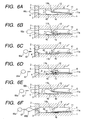
- Fig. 5 being a perspective view of a part of heads having been shown in Fig. 1, in particular, a protuberance bubble 41 elevating from the both parts of the movable member 11 as well as the meniscus of the liquid in the discharge port 4 will be described in detail.
- the shape of the stopper 12 and the shape of the low flow path resistant region 3a in the upstream side of the stopper 12 as shown in Fig. 5 is different from that shown in Fig. 1, but basic features are similar.
- a slight clearance exists between the wall surface of the both sides of the wall constructing the flow path 3 and the both side part of the movable member 11, and enables smooth displacement of the movable member 11.
- the bubbles 40 displace the movable member 11 in the growth step of foaming with the heat-generating body 10, and elevate to the upper face side of the movable member 11 via the above-described clearance to slightly invade to the low flow path resistant region 3a.
- This elevated bubble 41 having invaded comes around to the back surface (the bubble generation region and the opposite surface) of the movable 11 to control blurring of the movable member 11 to stabilize the discharge features.
- the elevated bubble 41 promotes the liquid flow from the low flow path resistant region 3a to the bubble generation region to swiftly finalize disappearance with the above-described rapid meniscus retraction from the discharge port 4 side.
- the liquid flow that the elevated bubble 41 causes will hardly store and hold the bubble at the corner of the movable member 11 and the flow path 3.
- the discharged droplet 66 is discharged under a state resembling a liquid pillar having a bulb part at the tip.
- This issue is the same also in the conventional head structure, but in the present embodiment, when the bubble growth step displaces the movable member 11 and this displaced movable member 11 contacts the stopper 12, the flow path 3 having the bubble generation region removes the discharge port and a substantially closed space is formed.
- the tailing part does not continue to be pulled by the meniscus forever so that the discharge velocity does not decrease, but the distance between the discharged droplets 66 and the satellite dots are shortened, and therefore the satellite dot is drawn in by the so-called strip stream phenomena behind the discharged droplet 66.
- the discharged droplet 66 and the satellite dots can be united, and the liquid discharge head almost lacking the satellite dots can be provided.
- the movable member 11 is provided only for restraining only the bubbles 40 growing in the upstream direction on the liquid flow toward the discharge port 4. Further preferably, the free end 11b of the movable member 11 is disposed in the substantially center part of the bubble generation region. This construction serves to enable to control the back wave to the upstream side due to bubble growth as well as inertia force of the liquid that is not directly influential for the liquid discharge, and to gently direct the growing component of the bubbles 40 toward the downstream side in the direction of the discharge port 4.
- this construction will make high speed meniscus retraction firm.
- the movable member 11 when disappearing step of the bubble 40 progresses and the repulsion of the movable member 11 surpasses the liquid movement force in the upstream direction due to bubble growth, the movable member 11 is displaced downward so as to return to the initial state, and accompanied hereby a flow in the downstream direction also occurs in the low flow path resistant region 3a as well.
- the flow in the downstream direction in the low flow path resistant region 3a is small and thus will constitute a large flow rapidly and flows into the flow path 3 via the stopper 12.
- liquid movement in the downstream direction toward this discharge port 4 can serve to rapidly decelerate the retraction of the above described meniscus and to converge vibration of the meniscus at a high velocity.
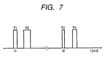
- Fig. 7 is a graph schematically showing the wave form of the voltage pulse to be applied to the heat-generating body 10.
- the voltage pulse is applied to the heat-generating body 10 for the first time so that the bubble 40 is formed and the first discharge droop 66a is formed.
- a double pulse consisting of a prepulse P1 and a main pulse P2 is applied at a predetermined time t1.
- application of the prepulse P1 preheats the heat-generating body 10 and the liquid in the vicinity thereof so that the liquid can be caused to foam well when the main pulse P2 has been applied subsequently.
- the movable member 11 is brought into contact with the stopper 12 to undergo displacement until it reaches the state to substantially close the upstream side so that the movement of the liquid in the upstream direction is largely limited.
- the bubble 40 grows largely to the downstream side.
- the voltage pulse is applied to the heat-generating body 10 for the second time so that foaming for the second time starts. That is, under this state, the meniscus is in the vicinity of the liquid discharge face, and a constant liquid refilling is completed to the upstream side of the heat-generating body 10, and therefore, the voltage pulse applied from this state to start foaming serves to enable the liquid to be discharged well.
- a double pulse drive is executed by applying the prepulse P3 and the main pulse P4 at the time t2 after a predetermined time has lapsed from the time t1.
- foaming for the second time is started substantially at the same time when the main pulse P4 is applied. Accordingly, in the present embodiment, as described above, the statement that foaming starts at the timing when the bubble 40 remains only in the vicinity of the downstream side end part of the bubble generation region means to start application of the main pulse P4 at this timing.
- the bubble 40 starts growing as shown in Fig. 6D and the movable member 11 starts upward displacement.
- the bubble 40 is conditioned to partially remain in the downstream side, and therefore foaming is executed under a state that a liquid flow from the upstream side accompanied by disappearance of the remaining bubbles has taken place.
- This can serve to cause the liquid flow taking place accompanied by growth of the bubble 40 to act on the liquid flow accompanied by bubble disappearance after liquid discharge for the previous time so as to give rise to a liquid flow in the discharge direction immediately.
- the meniscus will be retracted less than at the time of liquid discharge for a single session, and starts its movement from the position shown in Fig. 6C to the downstream side as shown in Fig. 6D.
- the liquid flow accompanied by bubble disappearance formed in the previous liquid discharge is decelerated immediately before the end of the disappearance as bubble disappearance progresses. Therefore, before disappearance of the bubbles having been formed at the previous time of liquid discharge comes to an end, foaming for the second session and onwards starts so that influence of the liquid flow as described above can be obtained effectively.
- the bubble 40 will further grow so that the second discharged droplet 66b is discharged.
- the volume of the second discharged droplet 66b gets larger than that for the first time.
- the foaming for the second time starts, and therefore the liquid flow toward the heat-generating body 10 from the discharge port 4 is cancelled due to foaming for the second time, and moreover, at the time when liquid flow to the further upstream side is formed, momentum of the liquid flow from the upstream side of the heat-generating body 10 is added to the liquid flow toward the discharge port 4 to accelerate the flow. Therefore, compared with the speed v 1 of the first discharged droplet 66a, the speed v 2 of the second discharged droplet 66b can be arranged to be faster.
- the second discharged droplet 66b it is possible to arrange the second discharged droplet 66b to catch up with the liquid pillar type satellite 67 immediately after separation so as to execute integration, that is, to cause the second discharged droplet 66b to capture the satellite 67.
- the volume after the second discharged droplet 66b has captured the satellite 67 will become V d2 +V ds1 , and of course it is possible to make (V d2 +V ds1 )>V dm1 .
- discharge amount of the liquid for the first discharged droplet 66a and the second discharged droplet 66b are changed so that, for example, sizes of the forming pixel are changed and the gradation is changed to enable execution, etc. of recording.
- the satellite 67 at the first liquid discharge is caused to be absorbed by the second discharged droplet 66b so that the gradation difference can be made large.
- a plurality of discharged liquid droplets are discharged in a consecutive manner and these plurality of discharged liquid droplets are arranged to be integrated in the course of flying to the recording medium to be recorded so that, for example, multi-gradation recording can be executed.
- the voltage pulse for the second liquid discharge is applied to foam the liquid, so that the liquid discharge can be executed well in a consecutive manner at an time interval that is short beyond the limit of the prior art, that is, the liquid discharge head can be driven at an extremely high frequency.
- the discharge amount for the second liquid discharge can be made abundant, and moreover the discharge velocity can be made fast.
- energy efficiency for discharge can be improved.
- the liquid flow from the upstream side taking place by high speed refilling of the liquid that is accompanied by disappearance of the bubble 40 having been formed at the preceding liquid discharge can be made to attribute to the succeeding liquid discharge effectively. That is, a part of applied energy at the preceding liquid discharge can be utilized as energy for the succeeding liquid discharge. Under the circumstances, even if the energy to be applied at the second liquid discharge and onwards is made less than the energy to be applied at the first liquid discharge, the energy to effectively contribute to discharge can be made equivalent to the energy for the first time or more than that.
- the present embodiment directs its attention to this issue, and is to show a method for discharging liquid by making the energy to be applied at the second liquid discharge and onwards in consecutive discharge less than the energy to be applied at the first liquid discharge.
- a method for discharging liquid by making the energy to be applied at the second liquid discharge and onwards in consecutive discharge less than the energy to be applied at the first liquid discharge.
- to be concrete an example to change pulse width of the voltage pulse to be applied to the heat-generating body 40 so as to change the energy to be applied is shown.
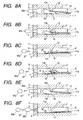
- the voltage pulse is applied to the heat-generating body 10 at first so that the first discharged droplet 66a is discharged as shown in Fig. 8A.
- a double pulse consisting of a prepulse P1 and a main pulse P2 is applied at a predetermined time t1.
- the bubble 40 becomes the maximum foam, and thereafter, as shown in Fig. 8B, starts undergoing bubble disappearance to lose volume largely in particular in the upstream side.
- the second voltage pulse is applied to start the second foaming.
- a double pulse consisting of a prepulse P3 and a main pulse P4 is applied.
- the pulse widths of these prepulse P3 and main pulse P4 are made shorter than the pulse width at the first foaming.
- the pulse width of the prepulse P1 was set at 0.7 ⁇ s and the pulse width of the main pulse P2 was set at 1.3 ⁇ s while for the second time, the pulse width of the prepulse P3 was set at 0.4 ⁇ s and the pulse width of the main pulse P4 was set at 0.9 ⁇ s.
- the timing for starting the second foaming will be substantially the same as the timing to apply the main pulse P4 as described above. Accordingly, since the bubble 40 given rise to by the first foaming starts foaming at a timing left only in the vicinity of the downstream side end part of the bubble generation region, the voltage pulse is applied so that application of the main pulse P4 starts at this timing.
- application of the second voltage pulse P3 started at the time t2 being 17 ⁇ s after the time t1 when application of the first voltage pulse P1 had started to adjust the foaming timing.
- the liquid is caused to bubble so that the second discharged droplet 66b is caused to be discharged as shown in Fig. 8E.
- the amount of the second discharged droplet 66b can be equivalent to or more than that of the first discharged droplet 66a corresponding with necessity due to action of the liquid flow of refilling.
- the speed of the discharged droplet 66a can be made equivalent to or faster than that of the first discharged droplet 66a, and as shown in Fig.
- the satellite 67 having been formed at the previous liquid discharge can be caused to be captured by the second discharged droplet 66b.
- the satellite 67 while the satellite 67 is in the state of liquid pillar, it can be caused to be captured by the second discharged droplet 66b, and moreover, corresponding with necessity, it is also possible to cause the first discharged droplet 66a to be captured by the second discharged droplet 66b during flight.
- a part of energy having been supplied to the heat-generating body 10 at the preceding liquid discharge can be made to effectively attribute to the succeeding liquid discharge in a mode of liquid flow of high speed refilling, and supply of energy less than that at the preceding liquid discharge to the heat-generating body 10 can cause liquid droplets of amount and speed equivalent to or more than those at the preceding liquid discharge to be discharged.
- the energy to be supplied for obtaining the required discharge performance can be suppressed much. Therefore, energy saving of the consumption energy in the liquid discharge head can be planned, and unnecessary temperature increase of the liquid discharge head can be suppressed. Accordingly, according to the present embodiment, in particular, as in the method for discharging liquid in the present invention, also in the case where the liquid discharge head is driven at a high speed, suppression of the supplied energy to generate little, the power as well as the driving circuit will not have to be made to have large quantity, and cost increase can be suppressed. In addition, changes in discharge features as well as decrease in reliability due to heating in the liquid discharge head can be suppressed.
- the voltage pulse for the succeeding liquid discharge is applied, so that the liquid discharge can be executed well in a consecutive manner at a time interval that is short beyond the limit of the prior art, that is, the liquid discharge head can be driven at an extremely high frequency.
- the discharge amount of the discharge drop at the time of consecutive discharge can be made abundant, and moreover the discharge velocity can be made fast.
- a portion of the generated energy at the preceding liquid discharge can be caused to attribute to the succeeding liquid discharge, and energy efficiency for liquid discharge can be improved.
- the discharge amount of the discharge drop for the first session as well as the discharge amount of the discharge drop for the second session and onwards are changed, and the discharged liquid droplets for the second session and onwards are made to capture the satellite of the preceding discharge drop and moreover the preceding discharge drop itself so that the attached liquid amount onto respective image point is caused to change and gradation recording can be made suitably.
- the amount and speed of liquid droplets to take place by foaming for the second session and onwards can be made equivalent to those for the first session or not less than the first session. Therefore, energy saving can be contemplated, and heating in the liquid discharge head can be suppressed.
Claims (8)
- Verfahren zum Ausgeben von Flüssigkeit mit einem Erwärmungsschritt einer Flüssigkeit, die einen Flüssigkeitsdurchflussweg (3) füllt, mit einem Wärme generierenden Körper (10), um eine Blase (40) in der Flüssigkeit zu generieren, und einem Ausgabeschritt der Flüssigkeit von einem Ausgabeanschluss (4), der mit dem Flüssigkeitsdurchflussweg (3) kommuniziert, unter Verwendung einer Energie, die in der Blasengenerierung erzeugt wird, wobei die Schritte mehrere Male wiederholt werden, um eine Vielzahl von Flüssigkeitströpfchen (66) in einer aufeinanderfolgenden Weise auszugeben,
dadurch gekennzeichnet, dass
die Antriebsenergie für eine Flüssigkeitsausgabe, die in einem Zustand fortgeführt wird, in dem ein Teil der Blasen (40), die während einer vorhergehenden Flüssigkeitsausgabe ausgebildet worden ist, zurückbleibt, zu dem Wärme generierenden Körper (10) zugeführt wird, so dass
ein Satellit (67), der bei der vorhergehenden Flüssigkeitsausgabe ausgebildet wurde, wobei ein Teil, das hinter dem ausgegebene Flüssigkeitströpfchen (66a) folgt, abetrennt ist, durch das ausgegebene Flüssigkeitströpfchen (66b) bei einer darauffolgenden Flüssigkeitsausgabe aufgefangen wird, während der Satellit (67) in Form einer Flüssigkeitssäule ist, so dass das ausgegebene Flüssigkeitströpfchen (66b) mit dem Satellit (67) integriert ist. - Verfahren zum Ausgeben einer Flüssigkeit nach Anspruch 1, wobei ein Volumen des ausgegebenen Flüssigkeitströpfchens (66b), das bei einer zweiten Flüssigkeitsausgabe und weiter auszugeben ist, größer als ein Volumen des ausgegebenen Flüssigkeitströpfchens (66a) ist, wenn eine Flüssigkeitsausgabe von einem normalen Zustand ausgeführt wird.
- Verfahren zum Ausgeben von Flüssigkeit nach Anspruch 1 oder 2, wobei eine Geschwindigkeit der ausgegebenen Flüssigkeitströpfchen (66b), die zum Zeitpunkt einer zweiten Flüssigkeitsausgabe und weiter ausgegeben worden sind, schneller als eine Geschwindigkeit des ausgegebenen Flüssigkeitströpfchen (66a) zu einem Zeitpunkt ist, wenn eine Flüssigkeitsausgabe von einem normalen Zustand ausgeführt wird.
- Verfahren zum Ausgeben von Flüssigkeit nach Anspruch 1, wobei ein Volumen Vd2 eines nachfolgenden ausgegebenen Flüssigkeitströpfchens (66b) größer als eine Summe eines Volumens Vdm1 eines vorhergehenden ausgegebenen Flüssigkeitströpfchens (66a) und eines Volumens Vds1 seines Satelliten (67) gemacht ist, d.h. um Vd2 > (Vdm1 + Vds1) zu erfüllen.
- Verfahren zum Ausgeben einer Flüssigkeit nach einem der vorhergehenden Ansprüche, wobei eine Vielzahl von ausgegebenen Flüssigkeitströpfchen (66a, 66b) von dem gleichen Ausgabeanschluss (4) durch Verwenden eines Flüssigkeitsausgabekopfs ausgegeben werden, wobei der Flüssigkeitsausgabekopf hat:einen Wärme generierenden Körper (10), um thermische Energie zum Generieren einer Blase (40) in einer Flüssigkeit zu generieren;der Ausgabeanschluss (4) ein Teil ist, um die Flüssigkeit auszugeben;der Flüssigkeitsdurchflussweg (3) mit dem Ausgabeanschluss (4) kommuniziert und einen Blasengenerierungsbereich hat, um eine Blase (40) in der Flüssigkeit zu generieren;eine Flüssigkeitskammer (6), um den Flüssigkeitsdurchflussweg (3) mit der Flüssigkeit zu versorgen;ein bewegliches Element (11), das in dem Blasengenerierungsbereich vorgesehen ist, um durch ein Wachstum der Blase (40) versetzt zu werden; undein Steuerglied (12), um die Versetzung eines beweglichen Elements (11) innerhalb eines gewünschten Bereichs zu steuern und der Wärme generierende Körper (10) sowie der Ausgabeanschluss (4) in einem geradlinig kommunizierenden Zustand sind, so dass die Flüssigkeit von dem Ausgabeanschluss (4) mit einer Energie bei dem Blasengenerierungsbereich ausgegeben wird, wobei das Steuerglied (12) vorgesehen ist, um dem Blasengenerierungsbereich des Flüssigkeitsdurchflusswegs (3) zugewandt zu sein, und der Flüssigkeitsdurchflussweg (3) den Blasengenerierungsbereich hat, der einen im Wesentlichen geschlossenen Raum mit Ausnahme des Ausgabeanschlusses (4) durch einen wesentlichen Kontakt zwischen dem versetzten beweglichen Element (4) und dem Steuerglied (12) bildet,wobei nach einem Fortschreiten eines Verschwindens der Blase (40), die durch eine vorhergehende Flüssigkeitsausgabe ausgebildet wurde, und unter einem Zustand, dass die Blase (40) nur bei der Ausgabeanschlussseite des Blasengenerierungsbereichs verbleibt und ein blasenfreier Abschnitt auf der Seite der Flüssigkeitskammer des Blasengenerierungsbereichs vorhanden ist, verursacht wird, dass die Flüssigkeit eine Blase (40) durch Versorgen des Wärme generierenden Körpers (10) mit Antriebsenergie für eine nachfolgende Flüssigkeitsausgabe generiert.
- Verfahren zum Ausgeben einer Flüssigkeit nach Anspruch 5, wobei die Vielzahl von ausgegebenen Flüssigkeitströpfchen (66a, 66b) in einer aufeinanderfolgenden Weise ausgegeben werden und die Vielzahl von ausgegebenen Flüssigkeitströpfchen (66a, 66b) in dem Verlauf eines Fliegens zu einem Aufzeichnungsmediums, das aufzuzeichnen ist, integriert werden.
- Verfahren zum Ausgeben von Flüssigkeit nach Anspruch 1 oder 5, wobei in einer zweiten Flüssigkeitsausgabe und weiter auf eine aufeinanderfolgende Weise eine geringere Energie als eine Energie, die zu dem Wärme generierenden Körper (10) in einer ersten Flüssigkeitsausgabe zugeführt wird, zu dem Wärme generierenden Körper zugeführt wird.
- Verfahren zum Ausgeben einer Flüssigkeit nach Anspruch 7, wobei in einer zweiten Flüssigkeitsausgabe und weiter in einer aufeinanderfolgenden Ausgabe ein Spannungsimpuls mit einer kürzeren Breite als ein Spannungsimpuls, der an dem Wärme generierenden Körper in einer ersten Flüssigkeitsausgabe angelegt wurde, zu dem Wärme generierenden Körper (10) zugeführt wird.
Applications Claiming Priority (2)
| Application Number | Priority Date | Filing Date | Title |
|---|---|---|---|
| JP2000227980 | 2000-07-27 | ||
| JP2000227980 | 2000-07-27 |
Publications (3)
| Publication Number | Publication Date |
|---|---|
| EP1176018A2 EP1176018A2 (de) | 2002-01-30 |
| EP1176018A3 EP1176018A3 (de) | 2003-07-30 |
| EP1176018B1 true EP1176018B1 (de) | 2007-10-03 |
Family
ID=18721355
Family Applications (1)
| Application Number | Title | Priority Date | Filing Date |
|---|---|---|---|
| EP01118120A Expired - Lifetime EP1176018B1 (de) | 2000-07-27 | 2001-07-26 | Verfahren zum Ausstossen von Flüssigkeit |
Country Status (4)
| Country | Link |
|---|---|
| US (1) | US6505903B2 (de) |
| EP (1) | EP1176018B1 (de) |
| AT (1) | ATE374694T1 (de) |
| DE (1) | DE60130709T2 (de) |
Families Citing this family (4)
| Publication number | Priority date | Publication date | Assignee | Title |
|---|---|---|---|---|
| US7177825B1 (en) * | 1999-05-11 | 2007-02-13 | Borders Louis H | Integrated system for ordering, fulfillment, and delivery of consumer products using a data network |
| JP2004025851A (ja) * | 2002-05-02 | 2004-01-29 | Canon Inc | インクジェット記録装置及び記録方法 |
| JP2008093853A (ja) * | 2006-10-06 | 2008-04-24 | Canon Inc | インクジェット記録装置およびインクジェット記録方法 |
| JP2021115786A (ja) * | 2020-01-27 | 2021-08-10 | キヤノン株式会社 | 液体吐出ヘッドおよび液体吐出モジュール |
Family Cites Families (5)
| Publication number | Priority date | Publication date | Assignee | Title |
|---|---|---|---|---|
| CA1127227A (en) | 1977-10-03 | 1982-07-06 | Ichiro Endo | Liquid jet recording process and apparatus therefor |
| CA1259853A (en) * | 1985-03-11 | 1989-09-26 | Lisa M. Schmidle | Multipulsing method for operating an ink jet apparatus for printing at high transport speeds |
| DE69409020T2 (de) * | 1993-02-05 | 1998-07-02 | Hewlett Packard Co | System zur Reduzierung der Antriebsenergie in einem thermischen Tintenstrahlschnelldrucker |
| US6116716A (en) | 1996-07-12 | 2000-09-12 | Canon Kabushiki Kaisha | Method for standardizing an ink jet recording head and an ink jet recording head for attaining such standardization, ink jet recording method, and information processing apparatus, and host apparatus |
| US6409317B1 (en) * | 1998-08-21 | 2002-06-25 | Canon Kabushiki Kaisha | Liquid discharge head, liquid discharge method and liquid discharge apparatus |
-
2001
- 2001-07-25 US US09/911,454 patent/US6505903B2/en not_active Expired - Fee Related
- 2001-07-26 DE DE60130709T patent/DE60130709T2/de not_active Expired - Fee Related
- 2001-07-26 EP EP01118120A patent/EP1176018B1/de not_active Expired - Lifetime
- 2001-07-26 AT AT01118120T patent/ATE374694T1/de not_active IP Right Cessation
Also Published As
| Publication number | Publication date |
|---|---|
| DE60130709D1 (de) | 2007-11-15 |
| DE60130709T2 (de) | 2008-07-24 |
| ATE374694T1 (de) | 2007-10-15 |
| US20020024566A1 (en) | 2002-02-28 |
| EP1176018A2 (de) | 2002-01-30 |
| EP1176018A3 (de) | 2003-07-30 |
| US6505903B2 (en) | 2003-01-14 |
Similar Documents
| Publication | Publication Date | Title |
|---|---|---|
| US6241350B1 (en) | Ink jet printing head and printing apparatus using same | |
| US6305080B1 (en) | Method of manufacture of ink jet recording head with an elastic member in the liquid chamber portion of the substrate | |
| JP2656481B2 (ja) | インクジエツト記録ヘツド | |
| JPH01306254A (ja) | インクジェットヘッド | |
| KR100340894B1 (ko) | 액체 토출 헤드, 액체 토출 방법 및 액체 토출 장치 | |
| JP3056191B1 (ja) | インクジェット式プリンタ用ヘッドの駆動装置および方法 | |
| JP2002144570A (ja) | 液滴吐出方法、画像形成方法、液体吐出装置およびヘッド | |
| EP1176018B1 (de) | Verfahren zum Ausstossen von Flüssigkeit | |
| JP2010149335A (ja) | 液滴吐出装置、液滴吐出方法および画像形成装置 | |
| JP3571856B2 (ja) | 液体吐出ヘッド及び液体吐出装置 | |
| JPH02184449A (ja) | インクジェットヘッドの駆動装置 | |
| US6761434B2 (en) | Liquid discharge head, element substrate, liquid discharging apparatus and liquid discharging method | |
| JP3787507B2 (ja) | 液体吐出方法 | |
| US6435670B1 (en) | Liquid discharge head, liquid discharge method, liquid discharge apparatus, recovery method for liquid discharge head, and fluid structure body | |
| JPH03295657A (ja) | インクジェットプリンタヘッド | |
| EP1177901B1 (de) | Flüssigkeitsausstosskopf, Flüssigkeitsausstossapparat und Flüssigkeitsausstossverfahren | |
| JPS6124194B2 (de) | ||
| JP3535816B2 (ja) | 液体吐出ヘッド、液体吐出装置、および液体吐出方法 | |
| JP2001150679A (ja) | インクジェットプリントヘッド | |
| JPH04292949A (ja) | 液体噴射記録ヘッドおよび該記録ヘッドを用いた記録装置 | |
| JP2002046273A (ja) | 液体吐出ヘッド、液体吐出ヘッドの製造方法、および液体吐出装置 | |
| JP3170326B2 (ja) | インクジェット記録ヘッドおよびインクジェット記録装置 | |
| JPH11170530A (ja) | インクジェットプリントヘッド、インクジェットプリンテイングデバイスおよびそれらの製造方法 | |
| JP2002103624A (ja) | 液体吐出ヘッド、素子基板、液体吐出装置及び液体吐出方法 | |
| JPS634958A (ja) | インクジエツトプリンタの印字ヘツド |
Legal Events
| Date | Code | Title | Description |
|---|---|---|---|
| PUAI | Public reference made under article 153(3) epc to a published international application that has entered the european phase |
Free format text: ORIGINAL CODE: 0009012 |
|
| AK | Designated contracting states |
Kind code of ref document: A2 Designated state(s): AT BE CH CY DE DK ES FI FR GB GR IE IT LI LU MC NL PT SE TR |
|
| AX | Request for extension of the european patent |
Free format text: AL;LT;LV;MK;RO;SI |
|
| PUAL | Search report despatched |
Free format text: ORIGINAL CODE: 0009013 |
|
| AK | Designated contracting states |
Designated state(s): AT BE CH CY DE DK ES FI FR GB GR IE IT LI LU MC NL PT SE TR |
|
| AX | Request for extension of the european patent |
Extension state: AL LT LV MK RO SI |
|
| RIC1 | Information provided on ipc code assigned before grant |
Ipc: 7B 41J 2/05 B Ipc: 7B 41J 2/14 A |
|
| 17P | Request for examination filed |
Effective date: 20031211 |
|
| AKX | Designation fees paid |
Designated state(s): AT BE CH CY DE DK ES FI FR GB GR IE IT LI LU MC NL PT SE TR |
|
| 17Q | First examination report despatched |
Effective date: 20040318 |
|
| GRAP | Despatch of communication of intention to grant a patent |
Free format text: ORIGINAL CODE: EPIDOSNIGR1 |
|
| GRAS | Grant fee paid |
Free format text: ORIGINAL CODE: EPIDOSNIGR3 |
|
| GRAA | (expected) grant |
Free format text: ORIGINAL CODE: 0009210 |
|
| AK | Designated contracting states |
Kind code of ref document: B1 Designated state(s): AT BE CH CY DE DK ES FI FR GB GR IE IT LI LU MC NL PT SE TR |
|
| REG | Reference to a national code |
Ref country code: GB Ref legal event code: FG4D |
|
| REG | Reference to a national code |
Ref country code: CH Ref legal event code: EP |
|
| REG | Reference to a national code |
Ref country code: IE Ref legal event code: FG4D |
|
| REF | Corresponds to: |
Ref document number: 60130709 Country of ref document: DE Date of ref document: 20071115 Kind code of ref document: P |
|
| NLV1 | Nl: lapsed or annulled due to failure to fulfill the requirements of art. 29p and 29m of the patents act | ||
| REG | Reference to a national code |
Ref country code: CH Ref legal event code: PL |
|
| PG25 | Lapsed in a contracting state [announced via postgrant information from national office to epo] |
Ref country code: LI Free format text: LAPSE BECAUSE OF FAILURE TO SUBMIT A TRANSLATION OF THE DESCRIPTION OR TO PAY THE FEE WITHIN THE PRESCRIBED TIME-LIMIT Effective date: 20071003 Ref country code: SE Free format text: LAPSE BECAUSE OF FAILURE TO SUBMIT A TRANSLATION OF THE DESCRIPTION OR TO PAY THE FEE WITHIN THE PRESCRIBED TIME-LIMIT Effective date: 20080103 Ref country code: ES Free format text: LAPSE BECAUSE OF FAILURE TO SUBMIT A TRANSLATION OF THE DESCRIPTION OR TO PAY THE FEE WITHIN THE PRESCRIBED TIME-LIMIT Effective date: 20080114 Ref country code: NL Free format text: LAPSE BECAUSE OF FAILURE TO SUBMIT A TRANSLATION OF THE DESCRIPTION OR TO PAY THE FEE WITHIN THE PRESCRIBED TIME-LIMIT Effective date: 20071003 Ref country code: CH Free format text: LAPSE BECAUSE OF FAILURE TO SUBMIT A TRANSLATION OF THE DESCRIPTION OR TO PAY THE FEE WITHIN THE PRESCRIBED TIME-LIMIT Effective date: 20071003 |
|
| PG25 | Lapsed in a contracting state [announced via postgrant information from national office to epo] |
Ref country code: PT Free format text: LAPSE BECAUSE OF FAILURE TO SUBMIT A TRANSLATION OF THE DESCRIPTION OR TO PAY THE FEE WITHIN THE PRESCRIBED TIME-LIMIT Effective date: 20080303 |
|
| PG25 | Lapsed in a contracting state [announced via postgrant information from national office to epo] |
Ref country code: AT Free format text: LAPSE BECAUSE OF FAILURE TO SUBMIT A TRANSLATION OF THE DESCRIPTION OR TO PAY THE FEE WITHIN THE PRESCRIBED TIME-LIMIT Effective date: 20071003 |
|
| EN | Fr: translation not filed | ||
| PG25 | Lapsed in a contracting state [announced via postgrant information from national office to epo] |
Ref country code: DK Free format text: LAPSE BECAUSE OF FAILURE TO SUBMIT A TRANSLATION OF THE DESCRIPTION OR TO PAY THE FEE WITHIN THE PRESCRIBED TIME-LIMIT Effective date: 20071003 |
|
| PLBE | No opposition filed within time limit |
Free format text: ORIGINAL CODE: 0009261 |
|
| STAA | Information on the status of an ep patent application or granted ep patent |
Free format text: STATUS: NO OPPOSITION FILED WITHIN TIME LIMIT |
|
| PG25 | Lapsed in a contracting state [announced via postgrant information from national office to epo] |
Ref country code: BE Free format text: LAPSE BECAUSE OF FAILURE TO SUBMIT A TRANSLATION OF THE DESCRIPTION OR TO PAY THE FEE WITHIN THE PRESCRIBED TIME-LIMIT Effective date: 20071003 |
|
| 26N | No opposition filed |
Effective date: 20080704 |
|
| PG25 | Lapsed in a contracting state [announced via postgrant information from national office to epo] |
Ref country code: FR Free format text: LAPSE BECAUSE OF FAILURE TO SUBMIT A TRANSLATION OF THE DESCRIPTION OR TO PAY THE FEE WITHIN THE PRESCRIBED TIME-LIMIT Effective date: 20080704 |
|
| PG25 | Lapsed in a contracting state [announced via postgrant information from national office to epo] |
Ref country code: GR Free format text: LAPSE BECAUSE OF FAILURE TO SUBMIT A TRANSLATION OF THE DESCRIPTION OR TO PAY THE FEE WITHIN THE PRESCRIBED TIME-LIMIT Effective date: 20080104 |
|
| PG25 | Lapsed in a contracting state [announced via postgrant information from national office to epo] |
Ref country code: MC Free format text: LAPSE BECAUSE OF NON-PAYMENT OF DUE FEES Effective date: 20080731 |
|
| PG25 | Lapsed in a contracting state [announced via postgrant information from national office to epo] |
Ref country code: IE Free format text: LAPSE BECAUSE OF NON-PAYMENT OF DUE FEES Effective date: 20080728 Ref country code: CY Free format text: LAPSE BECAUSE OF FAILURE TO SUBMIT A TRANSLATION OF THE DESCRIPTION OR TO PAY THE FEE WITHIN THE PRESCRIBED TIME-LIMIT Effective date: 20071003 |
|
| PGFP | Annual fee paid to national office [announced via postgrant information from national office to epo] |
Ref country code: DE Payment date: 20090731 Year of fee payment: 9 Ref country code: GB Payment date: 20090731 Year of fee payment: 9 |
|
| PG25 | Lapsed in a contracting state [announced via postgrant information from national office to epo] |
Ref country code: FI Free format text: LAPSE BECAUSE OF FAILURE TO SUBMIT A TRANSLATION OF THE DESCRIPTION OR TO PAY THE FEE WITHIN THE PRESCRIBED TIME-LIMIT Effective date: 20071003 |
|
| PG25 | Lapsed in a contracting state [announced via postgrant information from national office to epo] |
Ref country code: LU Free format text: LAPSE BECAUSE OF NON-PAYMENT OF DUE FEES Effective date: 20080726 |
|
| PG25 | Lapsed in a contracting state [announced via postgrant information from national office to epo] |
Ref country code: TR Free format text: LAPSE BECAUSE OF FAILURE TO SUBMIT A TRANSLATION OF THE DESCRIPTION OR TO PAY THE FEE WITHIN THE PRESCRIBED TIME-LIMIT Effective date: 20071003 |
|
| PG25 | Lapsed in a contracting state [announced via postgrant information from national office to epo] |
Ref country code: IT Free format text: LAPSE BECAUSE OF NON-PAYMENT OF DUE FEES Effective date: 20080731 |
|
| GBPC | Gb: european patent ceased through non-payment of renewal fee |
Effective date: 20100726 |
|
| PG25 | Lapsed in a contracting state [announced via postgrant information from national office to epo] |
Ref country code: DE Free format text: LAPSE BECAUSE OF NON-PAYMENT OF DUE FEES Effective date: 20110201 |
|
| REG | Reference to a national code |
Ref country code: DE Ref legal event code: R119 Ref document number: 60130709 Country of ref document: DE Effective date: 20110201 |
|
| PG25 | Lapsed in a contracting state [announced via postgrant information from national office to epo] |
Ref country code: GB Free format text: LAPSE BECAUSE OF NON-PAYMENT OF DUE FEES Effective date: 20100726 |