EP1175247B1 - Life-saving system for closed rooms, in particular tunnels - Google Patents
Life-saving system for closed rooms, in particular tunnels Download PDFInfo
- Publication number
- EP1175247B1 EP1175247B1 EP20000938517 EP00938517A EP1175247B1 EP 1175247 B1 EP1175247 B1 EP 1175247B1 EP 20000938517 EP20000938517 EP 20000938517 EP 00938517 A EP00938517 A EP 00938517A EP 1175247 B1 EP1175247 B1 EP 1175247B1
- Authority
- EP
- European Patent Office
- Prior art keywords
- shelter
- compressed air
- air
- vortex tube
- danger zone
- Prior art date
- Legal status (The legal status is an assumption and is not a legal conclusion. Google has not performed a legal analysis and makes no representation as to the accuracy of the status listed.)
- Expired - Lifetime
Links
Images

Classifications
-
- A—HUMAN NECESSITIES
- A62—LIFE-SAVING; FIRE-FIGHTING
- A62B—DEVICES, APPARATUS OR METHODS FOR LIFE-SAVING
- A62B13/00—Special devices for ventilating gasproof shelters
-
- E—FIXED CONSTRUCTIONS
- E21—EARTH DRILLING; MINING
- E21F—SAFETY DEVICES, TRANSPORT, FILLING-UP, RESCUE, VENTILATION, OR DRAINING IN OR OF MINES OR TUNNELS
- E21F11/00—Rescue devices or other safety devices, e.g. safety chambers or escape ways
Definitions
- Such spaces i.e. spaces that, due to their location, geometry, Equipment and / or expansion of an escape from fires or consequences of fire (smoke, poisonous gases, Heat, vapors, etc.) or only inappropriately allow it is considerable Dangers to life and limb connected.
- Such spaces (hereinafter referred to as “danger areas” are) for example tunnels, rooms with locks, cellars, high floors in High-rise buildings, rooms in (nuclear) power plants, clean rooms, laboratories etc.
- Tunnels and other danger areas are often provided with shelters (niches), they. usually do not offer active ventilation and / or cooling. Staying in such Shelters can therefore mean that people are only protected for a certain amount of time and are in mortal danger if the fire spreads or the consequences of a fire.
- the invention has for its object to a system suitable for hazardous areas create an active ventilation and cooling system and keep harmful substances away.
- DE-A-40 25 804 describes a device for the supply of cooled air in a room, whereby the cold flow outlet of a vortex tube into the room leads.
- Vortex tube is arranged in the room. Neither will discloses where the hot flow outlet leads.
- Much more only an air conditioning system for supply is cooled Air described in a room with a vortex tube.
- Vortex tubes are supplied with compressed air.
- the functioning of the vortex tube is briefly described below:
- a stream of compressed air is fed tangentially into a pipe.
- This compressed air flow is divided into two Partial flows on: A partial flow exits heated via a static throttle at one end of the pipe, the other partial flow exits cooled via a static orifice at the other end of the pipe.
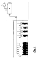
- Fig. 1 is the basic Circuit of such a system described:
- shelters 2 for accommodating groups of people
- Shelters 3 to accommodate groups of 4 or individuals, depending on how the spatial conditions in the tunnel are.
- shelters 2 or 3 Vortex tubes 5, from which cooled air exits into the shelters. This cooled air serves for breathing and cooling people or the shelter.
- a barrier to the Danger area e.g. door
- the compressed air is supplied via a line 6.
- This compressed air is over a Compressed air station provided, which consists of a wind boiler 7, a compressed air compressor 8 and if necessary, there is a compressed air dryer 9.
- the compressed air station can, however, in the tunnel itself also (preferably) be set up outside the tunnel.
- the pipeline 6 should be insulated (e.g. double-walled with mineral in between Thermal insulation, possibly also melt basalt to increase the temperature resistance be used).
- the wind boiler 7 should be designed so that it is large enough. Compressed air for the Provide the duration and volume of the largest fire to be assumed.
- the compressor 8 would be relatively small; moreover, in the event of danger, it is not inevitable Compressed air compressors must be started, i.e. the life-saving air is in one static system and is not subject to the reliability of moving components and Machine groups.
- the compressed air line 6 can be used from both sides of the tunnel entrance a corresponding compressed air device can be supplied. Likewise, the compressed air line 6 can be divided into several sub-lines to avoid damage to a pipeline To maintain pipe reserves.
- FIG. 2 A more precise circuit of the vortex tube system is shown in Fig. 2.
- the vortex tube 5 is with the compressed air line 6 is supplied from the air boiler 7, which in turn from Compressed air compressor 8 and possibly a compressed air dryer 9 is supplied with compressed air.
- the Wind boiler 7 is provided with a sump drain 10, via the condensed water vapor can be discharged outside.
- a pressure relief valve ensures that the pressure in 7 does not rise unacceptably and at Exceeds the maximum pressure blows through an outlet 11. Compressed air humidity can condense in a condenser 9 and then discharged through a drain 12 become. Possibly. it is possible and even sensible to have a small partial flow of the orifice 13 To drain compressed air continuously via the compressed air compressor 8. It is both a regular Functional control possible, on the other hand the compressed air compressor 8 is kept “warm” what Corrosion prevents prolonged standstill. To prevent compressed air from escaping when the To prevent compressed air compressor 8, a check valve 14 can be used.
- the compressed air line 6 enters the shelter 2, 3 and opens into a tap (in Fig. 2 as Ball valve shown).
- the tap 15 is normally, i.e. if the shelter is not occupied or operated, closed. People who visit the shelter in the event of danger, can open the tap 15 (e.g. via a lever or a chain, which are clearly identified and act only in one direction or via footboard that is connected to the tap 15 so that when entering the shelter via a bar, chain or the like opens automatically).
- the compressed air entering the swirl tube 16 tangentially occurs on Warm air outlet 17 heated via the throttle 19 and cooled at the cold air outlet 18 via the Fade out.
- the heated partial flow is through the hot air outlet 17 through the wall of the Sheltered area to the danger zone (again a positive pressure drop), the cooled air at the cold air outlet 18 is available to people in the shelter.
- the compressed air can also be used to operate an emergency power generator To enable lighting of the shelter.
- the partition between the shelter and the danger zone can be made of refractory or fire retardant material with good thermal insulation and is preferably as solid Wall with door / gate or only as door / gate.
Abstract
Description
Die Nutzung umschlossener Räume, also Räume, die aufgrund ihrer Lage, Geometrie, Ausstattung und/oder Ausdehnung eine Flucht vor Bränden oder Brandfolgen (Rauch, Giftgase, Hitze, Dämpfe usw.) nicht oder nur in unangemessener Weise zulassen, ist mit erheblichen Gefahren für Leib und Leben verbunden. Derartige Räume (nachstehend als "Gefahrenbereich" bezeichnet) sind beispielsweise Tunnel, Räume mit Schleusen, Keller, hochgelegene Etagen in Hochhäusern, Räume in (Kern)kraftwerken, Reinräume, Laboratorien usw.The use of enclosed spaces, i.e. spaces that, due to their location, geometry, Equipment and / or expansion of an escape from fires or consequences of fire (smoke, poisonous gases, Heat, vapors, etc.) or only inappropriately allow it is considerable Dangers to life and limb connected. Such spaces (hereinafter referred to as "danger areas" are) for example tunnels, rooms with locks, cellars, high floors in High-rise buildings, rooms in (nuclear) power plants, clean rooms, laboratories etc.
Tunnel und anderen Gefahrenbereiche werden häufig mit Schutzräumen (Nischen) versehen, sie. bieten allerdings meistens keine aktive Lüftung und/oder Kühlung. Der Aufenthalt in derartigen Schutzräumen kann daher zur Folge haben, daß Menschen nur eine gewisse Zeit geschützt sind und sich bei Ausbreitung des Brandes oder Brandfolgen in Lebensgefahr befinden.Tunnels and other danger areas are often provided with shelters (niches), they. usually do not offer active ventilation and / or cooling. Staying in such Shelters can therefore mean that people are only protected for a certain amount of time and are in mortal danger if the fire spreads or the consequences of a fire.
Überlebenswichtig sind dabei Atemluft, eine erträgliche Temperatur und die Abwesenheit von
schädlichen Substanzen (Rauch, Dämpfe, Gase, Ruß usw.).
Der Erfindung liegt die Aufgabe zugrunde, ein für Gefahrenräume geeignetes System zu schaffen, daß eine aktive Belüftung und Kühlung bietet und schädliche Substanzen fernhält. The invention has for its object to a system suitable for hazardous areas create an active ventilation and cooling system and keep harmful substances away.
Aus den Dokumenten DE 2430592 A und DE 106538 C ist bereits die Zufuhr von Frischluft in einen Gefahrenbereich zur Rauchverdrängung bekannt. Weiter ist aus der US 4 174 711 A bereits die Kühlung von Luft bekannt.From documents DE 2430592 A and DE 106538 C is already the supply of fresh air to a danger zone known for displacing smoke. Further from US 4 174 711 A already known the cooling of air.
Schließlich beschreibt die DE-A-40 25 804 eine Vorrichtung zur Zufuhr von gekühlter Luft in einem Raum, wobei der Kaltstromauslaß eines Wirbelrohres in den Raum führt. In der Schrift verbleibt jedoch unklar, ob das Wirbelrohr in dem Raum angeordnet ist. Auch wird nicht offenbart, wohin der Warmstromauslaß führt. Vielmehr wird lediglich eine Klimaanlage zur Zuführung gekühlter Luft in einen Raum mit einem Wirbelrohr beschrieben. Finally, DE-A-40 25 804 describes a device for the supply of cooled air in a room, whereby the cold flow outlet of a vortex tube into the room leads. However, it remains unclear in writing whether that Vortex tube is arranged in the room. Neither will discloses where the hot flow outlet leads. Much more only an air conditioning system for supply is cooled Air described in a room with a vortex tube.
Erfindungsgemäß wird diese Aufgabe durch die Merkmale des Hauptanspruchs gelöst, die Unteransprüche gegen bevorzugte Ausgestaltungen der Erfindung an.According to the invention this object is achieved by the features of the main claim which Subclaims against preferred embodiments of the invention.
Grundgedanke der Erfindung ist der Einsatz von Wirbelrohren im Schutzraum. Derartige Wirbelrohre werden mit Druckluft versorgt. Die Funktionsweise des Wirbelrohres ist nachfolgend kurz beschrieben:The basic idea of the invention is the use of vortex tubes in the shelter. such Vortex tubes are supplied with compressed air. The functioning of the vortex tube is briefly described below:
In ein Rohr wird tangential ein Druckluftstrom gegeben. Dieser Druckluftstrom teilt sich in zwei Teilströme auf: Ein Teilstrom tritt über eine statische Drossel am einen Rohrende erwärmt aus, der andere Teilstrom tritt über eine statische Blende am anderen Rohrende gekühlt aus. Der Druck und die Temperatur der Druckluft sowie das Verhältnis der beiden Teilströme bestimmt, wie stark die Druckluft am "kalten Ende" (Blendenseite) abgekühlt ist.A stream of compressed air is fed tangentially into a pipe. This compressed air flow is divided into two Partial flows on: A partial flow exits heated via a static throttle at one end of the pipe, the other partial flow exits cooled via a static orifice at the other end of the pipe. The Pressure and the temperature of the compressed air, as well as the ratio of the two partial flows, how much the compressed air has cooled at the "cold end" (orifice side).
Der Erfindung liegt die Idee zugrunde, eine lebensrettende Einrichtung zu schaffen, bei der die Zufuhr von Atemluft bei gleichzeitiger Kühlung dieser Luft und ein positives Druckgefälle zwischen Schutzraum und Gefahrenraum herbeigeführt wird. In Fig. 1 ist die grundsätzliche Schaltung einer solchen Anlage beschrieben:The invention is based on the idea of creating a life-saving device in which the Supply of breathing air while cooling this air and a positive pressure drop between the shelter and the danger zone. In Fig. 1 is the basic Circuit of such a system described:
Am Beispiel eines (langen) Tunnels wird nachstehend eine Erfindung beschrieben, welche für die
Rettung von Leben geeignet ist. Dabei zeigt:
Im Tunnel 1 befinden sich Schutzräume 2 (zur Aufnahme von Personengruppen) und/oder
Schutzräume 3 zur Aufnahme von Personengruppen 4 oder Einzelpersonen, anhängig davon, wie
die räumlichen Verhältnisse im Tunnel sind. In den Schutzräumen 2 oder 3 befinden sich
Wirbelrohre 5, aus welchen gekühlte Luft in die Schutzräume austritt. Diese gekühlte Luft dient
zur Atmung und Kühlung der Personen bzw. des Schutzraumes. Eine Absperrung zum
Gefahrenraum (z.B. Tür) hat eine gezielte "Undichtigkeit", durch welche die zugeführte Luft
entweichen kann und wegen des positiven Druckgefälles ein Eindringen gefährlicher Substanzen
oder von Flammen verhindert.In tunnel 1 there are shelters 2 (for accommodating groups of people) and / or
Die Druckluft wird über eine Leitung 6 zugeführt. Diese Druckluft wird über eine
Druckluftstation bereitgestellt, welche aus einem Windkessel 7, einem Druckluftverdichter 8 und
ggf einem Drucklufttrockner 9 besteht. Die Druckluftstation kann dabei im Tunnel selbst, aber
auch (vorzugsweise) außerhalb des Tunnels aufgestellt sein. Die Rohrleitung 6 sollte
wärmegedämmt ausgeführt sein (z.B. doppelwandig mit zwischenliegender mineralischer
Wärmedämmung, ggf. kann auch Schmelzbasalt zur Erhöhung der Temperaturresistenz
verwendet werden).The compressed air is supplied via a
Der Windkessel 7 soll dabei so ausgeführt werden, daß er groß genug ist. Druckluft für die
Zeitdauer und den Volumenbedarf des größten anzunehmenden Brandes bereitzustellen. Damit
wäre einerseits der Verdichter 8 relativ klein, zudem ist im Gefahrenfalle kein zwangsläufiges
Anspringen von Druckluftverdichtern notwendig, d.h. die lebensrettende Luft ist in einem
statischen System vorhanden und unterliegt nicht der Zuverlässigkeit bewegter Bauteile und
Maschinengruppen. The
Zwischen der Druckluftanlage bzw. dem Windkessel 7 und dem Wirbelrohr 5 im Schutzraum 2,
3 befinden sich keine Armaturen oder sonstige absperrenden Bauteile. Die Druckluft steht bis
zum Rettungsraum unabsperrbar zur Verfügung, was ein Versagen von Ventilen, Klappen usw.
ausschließt und auch keines Eingriffes von Menschen bedarfBetween the compressed air system or the
Aus Redundanzgründen kann die Druckluftleitung 6 von beiden Seiten des Tunneleingangs mit
einer entsprechenden Drucklufteinrichtung versorgt werden. Ebenso kann die Druckluftleitung 6
in mehrere Teilleitungen aufgeteilt werden, um bei einer Beschädigung einer Rohrleitung noch
Rohrreserven vorzuhalten.For reasons of redundancy, the
Eine genauere Schaltung der Wirbelrohranlage ist in Fig. 2 dargestellt. Das Wirbelrohr 5 wird mit
der Druckluftleitung 6 aus dem Windkessel 7 versorgt, welcher wiederum vom
Druckluftverdichter 8 und ggf. einem Drucklufttrockner 9 mit Druckluft versorgt wird. Der
Windkessel 7 ist mit einem Sumpfablaß 10 versehen, über den kondensierten Wasserdampf nach
außen abgeführt werden kann.A more precise circuit of the vortex tube system is shown in Fig. 2. The
Ein Überdruckventil sorgt dafür, daß der Druck in 7 nicht unzulässig ansteigt und bei
Überschreiten des Maximaldruckes über einen Auslaß 11 abbläst. Feuchtigkeit der Druckluft
kann in einem Kondensator 9 kondensieren und anschließend über einen Ablaß 12 abgelassen
werden. Ggf. ist es möglich und sogar sinnvoll, über eine Blende 13 einen kleinen Teilstrom der
Druckluft über den Druckluftverdichter 8 ständig abzulassen. Damit ist sowohl eine regelmäßige
Funktionskontrolle möglich, zum anderen wird der Druckluftverdichter 8 "warm" gehalten, was
Korrosion bei längerem Stillstand vorbeugt. Um ein Austreten von Druckluft bei Stillstand des
Druckluftverdichters 8 vorzubeugen, kann ein Rückschlagventil 14 eingesetzt werden.A pressure relief valve ensures that the pressure in 7 does not rise unacceptably and at
Exceeds the maximum pressure blows through an
Die Druckluftleitung 6 tritt in den Schutzraum 2, 3 ein und mündet in einen Hahn (in Fig. 2 als
Kugelventil dargestellt). Der Hahn 15 ist im Normalfall, d.h. sofern der Schutzraum nicht belegt
bzw betrieben wird, geschlossen. Menschen, die im Gefahrenfall den Schutzraum aufsuchen,
können den Hahn 15 öffnen (z.B. über einen Hebel oder eine Kette, die eindeutig bezeichnet sind
und nur in eine Richtung wirken oder über Trittbrett, das mit dem Hahn 15 so verbunden ist, das
sich dieser bei Betreten des Schutzraums über eine Stange, Kette oder dgl. durch Belastung
selbstätig öffnet). Die in das Wirbelrohr 16 tangential eintretenden Druckluft tritt am
Warmluftauslaß 17 über die Drossel 19 erwärmt und am Kaltluftauslaß 18 gekühlt über die
Blende aus. Der erwärmte Teilstrom wird über den Warmluftauslaß 17 durch die Wand des
Schutzraumes zum Gefahrenbereich abgelassen (wiederum ein positives Druckgefälle), die
gekühlte Luft am Kaltluftauslaß 18 steht den Menschen im Schutzraum zur Verfügung.The
Die Druckluft kann auch zum Betreiben eines Notstromgenerators genutzt werden, um eine Beleuchtung des Schutzraums zu ermöglichen.The compressed air can also be used to operate an emergency power generator To enable lighting of the shelter.
Die Erfindung hat folgende Vorteile:
- Keine bewegten Teile im Schutzraum (bis auf z.B. ein handbetätigtes Kugelventil),
- Keine bewegte Mechanik am Wirbelrohr, die Robustheit des Wirbelrohres kann durch Material und Wandstärke beliebig gesteigert werden,
- Luftzufuhr und Kühlung erfolgen zwangsläufig, d.h. es muß nicht manipuliert oder geregelt werden,
- Die Abwärme des Wirbelrohres kann - wegen des höheren Druckes - problemlos in den Gefahrenraum abgegeben werden,
- Keine Wärmeaustauscher, d.h. keine Wartung, keine Verschmutzung,
- Geringer Platzbedarf. darüberhinaus sehr flexibel an örtliche Verhältnisse anpassbar,
- Luftmenge ist hoch genug, um ein positives Druckgefälle zum Gefahrenraum aufrecht zu erhalten,
- Geringer Platzbedarf für die Druckluftleitung, gute Wärmedämmbarkeit der Leitung,
- Verschmutzung der Einrichtung ist ohne negative Auswirkung auf Leistung und Funktion des Wirbelrohres,
- Gute Redundanzverhältnisse (mehrere Drucklufterzeuger möglich, große Windkessel, getrennte Leitungen, Plazierung der Druckluftversorgungseinrichtungen z.B. an beiden Enden des Tunnels,
- Einfache Bedienung (Not"hebel", Reißkette o.ä.), d.h. die Luftzufuhr und Kühlung kann ohne Fachwissen vom Laien bedient werden.
- No moving parts in the shelter (except for a manually operated ball valve),
- No moving mechanics on the vortex tube, the robustness of the vortex tube can be increased by material and wall thickness,
- Air supply and cooling are inevitable, ie there is no need to manipulate or regulate
- The waste heat from the vortex tube can - due to the higher pressure - be easily released into the danger area,
- No heat exchangers, ie no maintenance, no pollution,
- Little need for space. furthermore very flexibly adaptable to local conditions,
- Air volume is high enough to maintain a positive pressure drop to the danger zone,
- Small space requirement for the compressed air line, good thermal insulation of the line,
- Soiling of the device has no negative impact on the performance and function of the vortex tube,
- Good redundancy conditions (several compressed air generators possible, large wind boilers, separate lines, placement of the compressed air supply facilities, e.g. at both ends of the tunnel,
- Simple operation (emergency "lever", tear chain or similar), ie the air supply and cooling can be operated by laypersons without specialist knowledge.
Die Trennwand zwischen Schutzraum und Gefahrenraum kann aus feuerfestem oder feuerhemmendem Material mit guter Wärmedämmung bestehen und ist vorzugsweise als feste Wand mit Tür/Tor oder nur als Tür/Tor ausgeführt. Undichtigkeiten bei "geschlossener" Tür sind gewollt, um die eintretende kalte Atemluft aus dem Wirbelrohr mit positivem Druckgefälle zum Gefahrenbereich abzuführen, was ein Eindringen von Flammen, Gasen, Ruß, Dämpfen oder anderen Substanzen verhmdert. Wegen des Überdruckes im Schutzraum ist ein Öffnen der Tür/des Tores sicher möglich, wenn später eintreffende Personen den Schutzraum noch erreichen wollen.The partition between the shelter and the danger zone can be made of refractory or fire retardant material with good thermal insulation and is preferably as solid Wall with door / gate or only as door / gate. There are leaks when the door is "closed" wanted to keep the incoming cold air from the vortex tube with a positive pressure drop Dissipate the danger area, which is the ingress of flames, gases, soot, or vapors other substances Because of the overpressure in the shelter, opening the Door / gate safely possible if people arriving later still reach the shelter want.
Claims (5)
- Apparatus for the supply of cooled air to a shelter (2, 3) located in a danger zone, characterized by a vortex tube (16), located in the shelter (2, 3) and whose cold flow outlet (18) leads into the shelter (2, 3) and whose hot flow outlet (17) leads into the danger zone.
- Apparatus according to claim 1, characterized by a cock (15) located in the shelter (2, 3) giving access to compressed air into the vortex tube (16) and operable by persons located in said shelter.
- Apparatus according to claim 1, characterized by an air chamber (7) located outside the danger zone and a compressed air pipeline (6) leading from the air chamber (7) to the shelter (2, 3).
- Apparatus according to claim 3, characterized in that the compressed air pipeline (6) is thermally insulated.
- Apparatus according to claim 3 or 4, characterized in that with the shelter (2, 3) are associated two air chambers (7) and two compressed air pipelines (6), which extend in different directions away from the shelter (2, 3).
Applications Claiming Priority (3)
| Application Number | Priority Date | Filing Date | Title |
|---|---|---|---|
| DE19919740A DE19919740C2 (en) | 1999-04-30 | 1999-04-30 | Lifesaving system for enclosed spaces, especially tunnels |
| DE19919740 | 1999-04-30 | ||
| PCT/DE2000/001346 WO2001012266A1 (en) | 1999-04-30 | 2000-05-02 | Life-saving system for closed rooms, in particular tunnels |
Publications (2)
| Publication Number | Publication Date |
|---|---|
| EP1175247A1 EP1175247A1 (en) | 2002-01-30 |
| EP1175247B1 true EP1175247B1 (en) | 2004-10-27 |
Family
ID=7906442
Family Applications (1)
| Application Number | Title | Priority Date | Filing Date |
|---|---|---|---|
| EP20000938517 Expired - Lifetime EP1175247B1 (en) | 1999-04-30 | 2000-05-02 | Life-saving system for closed rooms, in particular tunnels |
Country Status (4)
| Country | Link |
|---|---|
| EP (1) | EP1175247B1 (en) |
| AT (1) | ATE280620T1 (en) |
| DE (2) | DE19919740C2 (en) |
| WO (1) | WO2001012266A1 (en) |
Cited By (1)
| Publication number | Priority date | Publication date | Assignee | Title |
|---|---|---|---|---|
| EP3181811A3 (en) * | 2015-12-16 | 2017-07-12 | Eureka Pumps AS | A tunnel emergency life support system |
Families Citing this family (4)
| Publication number | Priority date | Publication date | Assignee | Title |
|---|---|---|---|---|
| CN104534601A (en) * | 2015-01-12 | 2015-04-22 | 重庆大学 | Air energy storage and refrigerating system used in power outage accident of nuclear power plant main control room |
| CN105805553A (en) * | 2016-05-06 | 2016-07-27 | 上海核工程研究设计院 | Emergency meeting compressed air system of nuclear power station |
| DE102018005497B4 (en) * | 2018-07-11 | 2023-08-10 | Kastriot Merlaku | Device of a rescue system for people from a cave enclosed by water masses |
| NO345845B1 (en) * | 2020-04-14 | 2021-08-30 | Fossheim Solution | System for self-rescue of road users in one-lane road tunnel with two-way traffic |
Family Cites Families (6)
| Publication number | Priority date | Publication date | Assignee | Title |
|---|---|---|---|---|
| DE249605C (en) * | ||||
| DE106538C (en) * | ||||
| GB1438001A (en) * | 1973-06-26 | 1976-06-03 | Kg Smoke Dispersal Ltd | Fire safety systems |
| GB1591259A (en) * | 1976-10-19 | 1981-06-17 | Laing Nikolaus | Fire resistant enclosures |
| US4467796A (en) * | 1981-12-02 | 1984-08-28 | Beagley Arthur E | Emergency breathing air supply system and apparatus |
| DE4025804A1 (en) * | 1990-08-15 | 1992-02-20 | Joachim Scheuermann | Air conditioning system utilising vortex tube - supplies separate streams of hot and cold air |
-
1999
- 1999-04-30 DE DE19919740A patent/DE19919740C2/en not_active Expired - Fee Related
-
2000
- 2000-05-02 AT AT00938517T patent/ATE280620T1/en not_active IP Right Cessation
- 2000-05-02 EP EP20000938517 patent/EP1175247B1/en not_active Expired - Lifetime
- 2000-05-02 WO PCT/DE2000/001346 patent/WO2001012266A1/en active IP Right Grant
- 2000-05-02 DE DE50008425T patent/DE50008425D1/en not_active Expired - Fee Related
Cited By (1)
| Publication number | Priority date | Publication date | Assignee | Title |
|---|---|---|---|---|
| EP3181811A3 (en) * | 2015-12-16 | 2017-07-12 | Eureka Pumps AS | A tunnel emergency life support system |
Also Published As
| Publication number | Publication date |
|---|---|
| ATE280620T1 (en) | 2004-11-15 |
| DE50008425D1 (en) | 2004-12-02 |
| DE19919740C2 (en) | 2001-03-08 |
| DE19919740A1 (en) | 2000-11-23 |
| WO2001012266A1 (en) | 2001-02-22 |
| EP1175247A1 (en) | 2002-01-30 |
Similar Documents
| Publication | Publication Date | Title |
|---|---|---|
| DE102017005287B3 (en) | Safety cabinet for active electrical and / or electronic components | |
| EP3578895B1 (en) | Device and method for safe and energy-saving flushing of a housing | |
| WO1998040858A1 (en) | Switch cabinet with a fire extinguishing system | |
| EP3792572A1 (en) | Safety coil device for a heat pump | |
| EP1175247B1 (en) | Life-saving system for closed rooms, in particular tunnels | |
| DE69826507T2 (en) | METHOD AND SYSTEM FOR FACILITATING RESCUE AND EVACUATION MEASURES FROM CLOSED SPACES | |
| DE212016000036U1 (en) | System for cryotherapy | |
| DE3212715C2 (en) | ||
| DE1961837C3 (en) | Arrangement for smoke evacuation in the event of fire in multi-storey houses with an internal staircase | |
| DE102019121496A1 (en) | Safety flushing device for a heat pump | |
| DE102012019699A1 (en) | Personal protection system and method for operating a personal protection system | |
| DE10253264C5 (en) | Decentralized ventilation device and method for decentralized heating or cooling of a room | |
| DE102020118778A1 (en) | Safety flushing device for a heat pump | |
| DE19904428C2 (en) | Mechanical smoke and heat exhaust system | |
| EP1074276A2 (en) | Method of operating a sprinkler installation in a cold room | |
| EP0523283B1 (en) | Ventilation and installation unit for buildings | |
| EP3712531A1 (en) | Safety ventilation device for a heat pump | |
| DE1679211A1 (en) | System for mechanical discharge of exhaust gases from at least one gas-heated device | |
| DE2557636C2 (en) | Fire gas extraction device of a building or the like. | |
| DE3638361A1 (en) | Heating device | |
| DE4101547C2 (en) | CO¶2¶ disposal system for secure rooms, especially data security rooms | |
| DE19946046A1 (en) | Ventilation element has opening in wall with filter, housing, flame arrester, closure piece, and fireproof plates | |
| AT411619B (en) | Shut-off | |
| DE6911611U (en) | FIRE ARRANGEMENT FOR AIR OR EXHAUST DUCT. | |
| DE10216383A1 (en) | Fire extinguisher method and appliance involve reducing oxygen content of air, condensing water and washing it and drawing off excess gases |
Legal Events
| Date | Code | Title | Description |
|---|---|---|---|
| PUAI | Public reference made under article 153(3) epc to a published international application that has entered the european phase |
Free format text: ORIGINAL CODE: 0009012 |
|
| 17P | Request for examination filed |
Effective date: 20010308 |
|
| AK | Designated contracting states |
Kind code of ref document: A1 Designated state(s): AT BE CH CY DE DK ES FI FR GB GR IE IT LI LU MC NL PT SE |
|
| GRAP | Despatch of communication of intention to grant a patent |
Free format text: ORIGINAL CODE: EPIDOSNIGR1 |
|
| GRAS | Grant fee paid |
Free format text: ORIGINAL CODE: EPIDOSNIGR3 |
|
| GRAA | (expected) grant |
Free format text: ORIGINAL CODE: 0009210 |
|
| AK | Designated contracting states |
Kind code of ref document: B1 Designated state(s): AT BE CH CY DE DK ES FI FR GB GR IE IT LI LU MC NL PT SE |
|
| PG25 | Lapsed in a contracting state [announced via postgrant information from national office to epo] |
Ref country code: IT Free format text: LAPSE BECAUSE OF FAILURE TO SUBMIT A TRANSLATION OF THE DESCRIPTION OR TO PAY THE FEE WITHIN THE PRESCRIBED TIME-LIMIT;WARNING: LAPSES OF ITALIAN PATENTS WITH EFFECTIVE DATE BEFORE 2007 MAY HAVE OCCURRED AT ANY TIME BEFORE 2007. THE CORRECT EFFECTIVE DATE MAY BE DIFFERENT FROM THE ONE RECORDED. Effective date: 20041027 Ref country code: NL Free format text: LAPSE BECAUSE OF FAILURE TO SUBMIT A TRANSLATION OF THE DESCRIPTION OR TO PAY THE FEE WITHIN THE PRESCRIBED TIME-LIMIT Effective date: 20041027 Ref country code: IE Free format text: LAPSE BECAUSE OF FAILURE TO SUBMIT A TRANSLATION OF THE DESCRIPTION OR TO PAY THE FEE WITHIN THE PRESCRIBED TIME-LIMIT Effective date: 20041027 Ref country code: FI Free format text: LAPSE BECAUSE OF FAILURE TO SUBMIT A TRANSLATION OF THE DESCRIPTION OR TO PAY THE FEE WITHIN THE PRESCRIBED TIME-LIMIT Effective date: 20041027 |
|
| REG | Reference to a national code |
Ref country code: GB Ref legal event code: FG4D Free format text: NOT ENGLISH |
|
| REG | Reference to a national code |
Ref country code: CH Ref legal event code: EP |
|
| REG | Reference to a national code |
Ref country code: IE Ref legal event code: FG4D Free format text: GERMAN |
|
| REF | Corresponds to: |
Ref document number: 50008425 Country of ref document: DE Date of ref document: 20041202 Kind code of ref document: P |
|
| PG25 | Lapsed in a contracting state [announced via postgrant information from national office to epo] |
Ref country code: GR Free format text: LAPSE BECAUSE OF FAILURE TO SUBMIT A TRANSLATION OF THE DESCRIPTION OR TO PAY THE FEE WITHIN THE PRESCRIBED TIME-LIMIT Effective date: 20050127 Ref country code: DK Free format text: LAPSE BECAUSE OF FAILURE TO SUBMIT A TRANSLATION OF THE DESCRIPTION OR TO PAY THE FEE WITHIN THE PRESCRIBED TIME-LIMIT Effective date: 20050127 Ref country code: SE Free format text: LAPSE BECAUSE OF FAILURE TO SUBMIT A TRANSLATION OF THE DESCRIPTION OR TO PAY THE FEE WITHIN THE PRESCRIBED TIME-LIMIT Effective date: 20050127 |
|
| GBT | Gb: translation of ep patent filed (gb section 77(6)(a)/1977) |
Effective date: 20050110 |
|
| PG25 | Lapsed in a contracting state [announced via postgrant information from national office to epo] |
Ref country code: ES Free format text: LAPSE BECAUSE OF FAILURE TO SUBMIT A TRANSLATION OF THE DESCRIPTION OR TO PAY THE FEE WITHIN THE PRESCRIBED TIME-LIMIT Effective date: 20050207 |
|
| REG | Reference to a national code |
Ref country code: CH Ref legal event code: NV Representative=s name: ISLER & PEDRAZZINI AG |
|
| NLV1 | Nl: lapsed or annulled due to failure to fulfill the requirements of art. 29p and 29m of the patents act | ||
| PG25 | Lapsed in a contracting state [announced via postgrant information from national office to epo] |
Ref country code: LU Free format text: LAPSE BECAUSE OF NON-PAYMENT OF DUE FEES Effective date: 20050502 Ref country code: AT Free format text: LAPSE BECAUSE OF NON-PAYMENT OF DUE FEES Effective date: 20050502 Ref country code: CY Free format text: LAPSE BECAUSE OF FAILURE TO SUBMIT A TRANSLATION OF THE DESCRIPTION OR TO PAY THE FEE WITHIN THE PRESCRIBED TIME-LIMIT Effective date: 20050502 Ref country code: GB Free format text: LAPSE BECAUSE OF NON-PAYMENT OF DUE FEES Effective date: 20050502 |
|
| REG | Reference to a national code |
Ref country code: IE Ref legal event code: FD4D |
|
| PG25 | Lapsed in a contracting state [announced via postgrant information from national office to epo] |
Ref country code: CH Free format text: LAPSE BECAUSE OF NON-PAYMENT OF DUE FEES Effective date: 20050531 Ref country code: LI Free format text: LAPSE BECAUSE OF NON-PAYMENT OF DUE FEES Effective date: 20050531 Ref country code: BE Free format text: LAPSE BECAUSE OF NON-PAYMENT OF DUE FEES Effective date: 20050531 Ref country code: MC Free format text: LAPSE BECAUSE OF NON-PAYMENT OF DUE FEES Effective date: 20050531 |
|
| PLBE | No opposition filed within time limit |
Free format text: ORIGINAL CODE: 0009261 |
|
| STAA | Information on the status of an ep patent application or granted ep patent |
Free format text: STATUS: NO OPPOSITION FILED WITHIN TIME LIMIT |
|
| ET | Fr: translation filed | ||
| 26N | No opposition filed |
Effective date: 20050728 |
|
| BERE | Be: lapsed |
Owner name: VORTEX G.M.B.H. & CO. SYSTEMTECHNIK KG Effective date: 20050531 |
|
| PG25 | Lapsed in a contracting state [announced via postgrant information from national office to epo] |
Ref country code: DE Free format text: LAPSE BECAUSE OF NON-PAYMENT OF DUE FEES Effective date: 20051201 |
|
| REG | Reference to a national code |
Ref country code: CH Ref legal event code: PL |
|
| GBPC | Gb: european patent ceased through non-payment of renewal fee |
Effective date: 20050502 |
|
| BERE | Be: lapsed |
Owner name: *VORTEX G.M.B.H. & CO. SYSTEMTECHNIK K.G. Effective date: 20050531 |
|
| PG25 | Lapsed in a contracting state [announced via postgrant information from national office to epo] |
Ref country code: PT Free format text: LAPSE BECAUSE OF NON-PAYMENT OF DUE FEES Effective date: 20050327 |
|
| PG25 | Lapsed in a contracting state [announced via postgrant information from national office to epo] |
Ref country code: FR Free format text: LAPSE BECAUSE OF NON-PAYMENT OF DUE FEES Effective date: 20050531 |
|
| REG | Reference to a national code |
Ref country code: FR Ref legal event code: ST Effective date: 20111007 |