EP1174751B1 - Holografisches Bildwiedergabe-Gerät und Bildwiedergabeverfahren - Google Patents
Holografisches Bildwiedergabe-Gerät und Bildwiedergabeverfahren Download PDFInfo
- Publication number
- EP1174751B1 EP1174751B1 EP01401933A EP01401933A EP1174751B1 EP 1174751 B1 EP1174751 B1 EP 1174751B1 EP 01401933 A EP01401933 A EP 01401933A EP 01401933 A EP01401933 A EP 01401933A EP 1174751 B1 EP1174751 B1 EP 1174751B1
- Authority
- EP
- European Patent Office
- Prior art keywords
- image
- hologram
- optical member
- holographic stereogram
- light
- Prior art date
- Legal status (The legal status is an assumption and is not a legal conclusion. Google has not performed a legal analysis and makes no representation as to the accuracy of the status listed.)
- Expired - Lifetime
Links
Images




Classifications
-
- G—PHYSICS
- G03—PHOTOGRAPHY; CINEMATOGRAPHY; ANALOGOUS TECHNIQUES USING WAVES OTHER THAN OPTICAL WAVES; ELECTROGRAPHY; HOLOGRAPHY
- G03H—HOLOGRAPHIC PROCESSES OR APPARATUS
- G03H1/00—Holographic processes or apparatus using light, infrared or ultraviolet waves for obtaining holograms or for obtaining an image from them; Details peculiar thereto
- G03H1/22—Processes or apparatus for obtaining an optical image from holograms
-
- G—PHYSICS
- G02—OPTICS
- G02B—OPTICAL ELEMENTS, SYSTEMS OR APPARATUS
- G02B30/00—Optical systems or apparatus for producing three-dimensional [3D] effects, e.g. stereoscopic images
- G02B30/20—Optical systems or apparatus for producing three-dimensional [3D] effects, e.g. stereoscopic images by providing first and second parallax images to an observer's left and right eyes
- G02B30/34—Stereoscopes providing a stereoscopic pair of separated images corresponding to parallactically displaced views of the same object, e.g. three-dimensional [3D] slide viewers
- G02B30/36—Stereoscopes providing a stereoscopic pair of separated images corresponding to parallactically displaced views of the same object, e.g. three-dimensional [3D] slide viewers using refractive optical elements, e.g. prisms, in the optical path between the images and the observer
-
- G—PHYSICS
- G03—PHOTOGRAPHY; CINEMATOGRAPHY; ANALOGOUS TECHNIQUES USING WAVES OTHER THAN OPTICAL WAVES; ELECTROGRAPHY; HOLOGRAPHY
- G03H—HOLOGRAPHIC PROCESSES OR APPARATUS
- G03H1/00—Holographic processes or apparatus using light, infrared or ultraviolet waves for obtaining holograms or for obtaining an image from them; Details peculiar thereto
- G03H1/04—Processes or apparatus for producing holograms
- G03H1/0402—Recording geometries or arrangements
- G03H1/0408—Total internal reflection [TIR] holograms, e.g. edge lit or substrate mode holograms
-
- G—PHYSICS
- G03—PHOTOGRAPHY; CINEMATOGRAPHY; ANALOGOUS TECHNIQUES USING WAVES OTHER THAN OPTICAL WAVES; ELECTROGRAPHY; HOLOGRAPHY
- G03H—HOLOGRAPHIC PROCESSES OR APPARATUS
- G03H1/00—Holographic processes or apparatus using light, infrared or ultraviolet waves for obtaining holograms or for obtaining an image from them; Details peculiar thereto
- G03H1/26—Processes or apparatus specially adapted to produce multiple sub- holograms or to obtain images from them, e.g. multicolour technique
- G03H1/268—Holographic stereogram
-
- G—PHYSICS
- G03—PHOTOGRAPHY; CINEMATOGRAPHY; ANALOGOUS TECHNIQUES USING WAVES OTHER THAN OPTICAL WAVES; ELECTROGRAPHY; HOLOGRAPHY
- G03H—HOLOGRAPHIC PROCESSES OR APPARATUS
- G03H2270/00—Substrate bearing the hologram
- G03H2270/20—Shape
- G03H2270/21—Curved bearing surface
-
- Y—GENERAL TAGGING OF NEW TECHNOLOGICAL DEVELOPMENTS; GENERAL TAGGING OF CROSS-SECTIONAL TECHNOLOGIES SPANNING OVER SEVERAL SECTIONS OF THE IPC; TECHNICAL SUBJECTS COVERED BY FORMER USPC CROSS-REFERENCE ART COLLECTIONS [XRACs] AND DIGESTS
- Y10—TECHNICAL SUBJECTS COVERED BY FORMER USPC
- Y10S—TECHNICAL SUBJECTS COVERED BY FORMER USPC CROSS-REFERENCE ART COLLECTIONS [XRACs] AND DIGESTS
- Y10S359/00—Optical: systems and elements
- Y10S359/90—Methods
Definitions
- the present invention relates to an apparatus and method for reproducing a 2-or 3-dimensional image from a hologram or a holographic stereogram on which two-or three-dimensional image data is recorded.
- a holographic stereogram is prepared by recording a number of rectangular or dot-shaped element holograms on one hologram-recording medium.
- the element holograms are original images that have been obtained by photographing an object, sequentially from different points of observation.
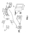
- a holographic stereogram containing parallax data concerning only the horizontal direction, for example, is prepared as is illustrated in FIG. 1.
- an object 100 is photographed from different observation points that lie in the same horizontal plane.
- a number of original images 101a-101e of the object 100 are thereby obtained.
- the original images 101a-101e which are rectangular element holograms, are sequentially recorded on a hotogram-recording medium 102.
- the holographic stereogram records image data representing rectangular element holograms that have been obtained by photographing an object, sequentially from different observation points that lie in the same horizontal plane.
- image data representing rectangular element holograms that have been obtained by photographing an object, sequentially from different observation points that lie in the same horizontal plane.
- An ordinary hologram is spaced from an illumination light source for reproducing a 3-dimensional image. A large space is required to reproduce the 3-dimensional image. To reproduce the 3-dimensional image in optimal conditions, the hologram and the light source need to have a particular positional relationship. This holds true of a holographic stereogram that consists of a plurality of element holograms,
- hologram and the illumination light source are combined, no space is required for illumination. This helps to reduce the size of the apparatus for reproducing 3-dimensional images.
- a 3-dimensional image can always be reproduced in the best possible conditions because the hologram and the illumination light source have a fixed positional relation.
- a 3-dimensional image may be reproduced in such conditions from a so-called "edge-lit hologram.”
- a recording medium bonded to a transparent light-introducing block is used to reproduce a 3-dimensional image from an edge-lit hologram.
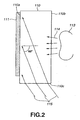
- a transmitting hologram of edge-lit type, from which a 3-dimensional image can be reproduced, is prepared as is illustrated in FIG. 2.
- a hologram-recording medium 111 is bonded to one surface 110a of a transparent light-introducing block 110.
- the light-introducing block 110 is made of transparent material such as glass or plastic and has an appropriate thickness.
- the medium 111 is bonded with index-matching liquid (not shown) to the light-introducing block 110. This prevents total reflection at the surface 110a of the block 110.
- Body light 114 from an object 113 is applied from the opposing surface 110b of the light-introducing block 110 to the hologram-recording medium 111.
- Reference light 115 is simultaneously applied from one end 110c of the block 110 to hologram-recording medium 111.
- a transmitting hologram of edge-lit type is thereby prepared.
- the hologram-recording medium is bonded to a light-introducing block made of, for example, glass. More precisely, as shown in FIG. 3, a hologram 121 is bonded with index-matching liquid (not shown) to one surface 120a of a light-introducing block 120. Image-reproducing light 123 is applied from one end 120b of the block 120 to the hologram 121. The hologram 121 diffracts the light passing through it. The light 124 diffracted forms a reproduced image 125, which is observed by an observer 126.
- the image-reproducing light 123 is incident on the one end 120b of the block 120 at angle of 60°. Since the light 123 is thus applied to the hologram 121 through the tight-introducing block 120, it is possible to prevent surface reflection at the interface between the hologram 121 and air. The larger the angle of incidence, the more readily the surface reflection can be prevented. In view of this it is considered that a compact apparatus can reproduce an image from the edge-lit hologram.
- the image-reproducing light 123 is incident on the one end 120b of the block 120 at an angle of 60°.
- the hologram 121 may have a length L of 30 mm and the one surface 120a of the block 120 may have a length that is at least nearly equal to the length L. In this case, the light-introducing block 120 needs to be at least 17.3 mm thick.
- edge-lit holograms are therefore inconvenient in view of transportation and storage. This is because, each edge-lit hologram is bonded to a light-introducing block that is 17.3 mm thick. That is, each edge-lit hologram must be transported and stored, together with such a long block.
- US 5,504,593 describes hologram-recording apparatus in which a transparent member is used for introducing light into the hologram-recording medium.
- the hologram recording medium is sandwiched between the transparent member and a reflector.
- the surface of the reflector remote from the hologram recording medium has parallel prisms thereon. Light which has passed through the hologram recording medium reflects from the inner side of the prism-bearing surface of the reflector and interferes with light transmitted through the transparent member.
- WO-A-9504294 describes edge-lit holograms of different types and includes a figure (figure 5) showing how an input coupler can be used to couple light into such a hologram via a waveguide.
- An object of the invention is to provide an image-reproducing apparatus that is smaller and lighter than the conventional apparatus that uses a light-introducing block to reproduce an image from an edge-lit hologram.
- the apparatus can therefore be easy to transport and store.
- the invention can provide an image-reproducing method, too, which uses no light-introducing blocks to reproduce images.
- the illumination light is applied to an interface between the optical member and the hologram or holographic stereogram, at a fixed incidence angle falling within a specific range, thereby to suppress surface reflection of the illumination light at the interface. More precisely, the fixed incidence angle ranges from 60° to 85°, with respect to a normal to the interface.
- the illumination light may be applied to an interface between the optical member and the hologram or holographic stereogram, at different incidence angles falling within a specific range, thereby to suppress surface reflection of the illumination light at the interface.
- the different incidence angles may range from 60 ° to 85°, with respect to a normal to the interface.
- the hologram or holographic stereogram and the optical member bonded thereto may be bent, forming a hollow cylinder, the inner surface of which is defined by said one major surface of the optical member.
- the illumination light may be applied to an inner surface of the hollow cylinder, thereby reproducing a 2- or 3-dimensional image from the hologram or holographic stereogram.
- the apparatus can reproduce an image from a hollow cylindrical hologram of edge-lit type.
- the angle at which the illumination light is applied to the prisms may be fixed or changed.
- an image-reproducing method of this invention is designed to reproduce an image from hologram or holographic stereogram, which records either 2-dimensional image data or 3-dimensional image data.
- the present invention provides an image-reproducing method of reproducing an image from a hologram or a holographic stereogram, which records either 2-dimensional image data or 3-dimensional image data, consisting of the steps of:
- the illumination light may be applied to an interface between the optical member and the hologram or holographic stereogram, at a fixed incidence angle falling within a specific range, thereby to suppress surface reflection of the illumination light at the interface.
- the hologram or holographic stereogram and the optical member bonded thereto may be bent, forming a hollow cylinder, the inner surface of which is defined by the optical member.
- the illumination light is applied to an inner surface of the hollow cylinder, thereby reproducing a 2- or 3- dimensional image from the hologram or holographic stereogram.
- the illumination light may be applied to an interface between the optical member and the hologram or holographic stereogram, at different incidence angles falling within a specific range, thereby to suppress surface reflection of the illumination light at the interface.
- the hologram or holographic stereogram and the optical member bonded thereto may be bent, forming a hollow cylinder, the inner surface of which is defined by the optical member.
- the illumination light is applied to an inner surface of the hollow cylinder, thereby reproducing a 2- or 3-dimensianal image from the hologram or holographic stereogram.
- the angle at which the illumination light is applied to the prisms may be fixed or changed.
- the present invention can provide an image-reproducing apparatus that is smaller and lighter than the conventional apparatus that uses a light-introducing block to reproduce an image from an edge-lit hologram.
- the apparatus can therefore be easy to transport and store.
- the invention can provide an image-reproducing method, too, which uses no light-introducing blocks to reproduce images.
- the apparatus and method of the invention can not only utilize the illumination light emitted from a light source, in the best possible manner, but also reproduce an image even if illumination light beams are applied at different angles to the different parts of the hologram.
- the present invention can provide a hollow cylindrical hologram of edge-lit type.
- the first embodiment is an image-reproducing apparatus 5 shown in FIG. 4.
- the apparatus 5 is designed to reproduce a holographic stereogram recording 3-dimensional imaged data.
- the apparatus comprises the holographic stereogram 6 and an optical member 7.
- the optical member 7 has a front side 7a and a rear side 7b opposing the front side 7a.
- the front side 7a consists of parallel triangular prisms, each having an incidence surface 8 and an inclined surface 23.
- the optical member 7 is bonded at its rear surface 7b to the holographic stereogram 6.
- Illumination light 9 is applied to the front surface 7a of the optical member 7 at a predetermined angle of, for example, 60°.
- the optical member 7 is made of, for example, optical glass, plastic or the like.
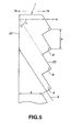
- the optical member 7 has a plurality of incidence surfaces 8 on the front side 7a. Each incidence surface 8 receives the illumination light 9 applied to it in the direction perpendicular to it. As FIG. 5 shows, the illumination light 9 is applied to the interface 22 between the holographic stereogram 6 and the optical member 7 at a predetermined incidence angle ⁇ .
- the incidence angle ⁇ is, for example, 60°, so that surface reflection can be prevented at the interface 22.
- the incidence angle ⁇ is one defined between the interface 22 and the normal H thereto.
- the angle between the surface 23 that each parallel triangular prism on the front side 7a of the optical member 7 defines with respect to the interface 22 is 60°, like the above-mentioned incidence angle. If the illumination light 9 applied from the light source (not shown) consists of parallel beams, it is applied to the incidence surfaces 8 at 90°. This effectively suppresses surface reflection at the incidence surfaces 8. From the angle at which the illumination light is applied to the optical member 7 it is known that the incidence angle ⁇ should fall within the range of 60° to 85°.
- the pitch p of the triangular prism of the optical member 7 The shorter the pitch p of the triangular prism of the optical member 7, the better. Generally, it is sufficient to set the pitch p at 0.5 mm or less. In the present embodiment. the pitch p is 100 ⁇ m.
- the incidence surfaces 8 are arranged on the front side 7a of the optical member 7, at intervals of 100 ⁇ m.
- the optical member 7 has a thickness d of 100 ⁇ m. It is thick enough to impart an adequate stiffness to the holographic stereogram 6. If supported firmly by the optical member, the holographic stereogram 6 can have desired optical properties.
- the illumination light 9 applied to the interface 22 at the angle ⁇ , through the incidence surfaces 8, is diffracted as it passes through the holographic stereogram 6.
- the light 20 thus diffracted forms a reproduced image, which an observer 21 may see.
- the image-reproducing apparatus 5 is smaller and lighter than the conventional apparatus having a light-introducing block and designed to reproduce a holographic stereogram of edge-lit type. It can therefore be more easily transported and stored.
- a system for preparing a holographic stereogram to be reproduced by the image-reproducing apparatus 5 that is the first embodiment of the invention will be described.
- the system records a plurality of rectangular element holograms on one recording medium, thereby to prepare a holographic stereogram that contains horizontal parallax data.
- the present invention can be applied to a system that records dot-shaped element holograms on a recording medium, thereby to prepare a holographic stereogram that contains both horizontal parallax data and vertical parallax data.
- the system is designed to prepare so-called "one-step holographic stereograms," each being a hologram-recording medium on which the pattern formed by interference between the body light and the reference light is recorded.
- the system comprises a data-processing section 1, a control computer 2 and a holographic stereogram printer 3.
- the section 1 processes the data to be recorded on the hologram-recording medium.
- the control computer 2 controls the other components of the system.
- the printer 3 has an optical system for preparing holographic stereograms.
- the data-processing section I has an image-processing computer I 1, a storage device 12, a photographing device 13, and a data-generating computer 14.
- the photographing device 13 incorporates a multi-lens camera or a mobile camera. It provides image data items D1, each containing parallax data.
- the data-generating computer 14 generates image data items D2, each containing the parallax data.
- a train of parallax images D3 is generated from the image data items D and the image data items D2.
- the image data items D1 supplied from the photographing device 13, each containing parallax data, represent the images of an object that the multi-lens camera has photographed at the same time, or the images of the object that the mobile camera has photographed at different times from different observation points.
- the image data items D2 generated by the computer 14, each containing parallax data, represent the CAD (Computer Aided Design) images, CG (Computer Graphics) images or the like, which have horizontal parallax with respect to each other.
- CAD Computer Aided Design
- CG Computer Graphics
- the image-processing computer 11 processes the parallax images D3, generating image data D4.
- the image data D4 is recorded in the storage device 12.
- the storage device 12 is a memory, a hard disc drive, or the like.
- the image data D4 is read from the storage device 12, image by image.
- the data D4 thus read is suppl ied, as image data D5, from the data-processing section 1 to the control computer 2.
- the image data D5 will be recorded on a hologram-recording medium.
- the control computer 2 drives the holographic stereogram printer 3.
- the printer 3 records the images represented by the data D5 supplied from the data-processing section 1. More precisely, the printer 3 records the data D5 on a hologram-recording medium 30, in the form of rectangular element holograms.
- the control computer 2 controls the shutter 32, display 41 and medium-feeding mechanism 50. all incorporated in the holographic stereogram printer 3. More specifically, the computer 2 supplies a control signal S1 to the shutter 32, thus opening or closing the shutter 32. It supplies the image data D5 to the display 41, which displays the image represented by the data D5. It supplies a control signal S2 to the medium-feeding mechanism 50, which feeds the hologram-recording medium 30 to a specific position. At this position, the data D5 is recorded on the hologram-recording medium 30.
- FIG. 7A is a plan view of the optical system incorporated in the holographic stereogram printer 3.
- FIG. 7B is a side view of the section of the optical system, which processes the body light.
- the holographic stereogram printer 3 comprises a laser 31, a shutter 32, and a half mirror 33.
- the laser 31 emits a laser beam L1.
- the shutter 32 and the half mirror 33 are arranged on the optical axis of the laser beam L1.
- the laser beam L1 has wavelength of about 532 nm.
- the shutter 32 is controlled by the control computer 2. It remains closed when the hologram-recording medium 30 need not be exposed to light at all. It is opened to apply light to the medium 30.
- the half mirror 33 receives the laser beam L2 that has passed through the shutter 32.
- the half mirror 33 splits the laser beam L2 into reference light L3 and body light L4.
- the reference light L3 is a part of the beam L2, which the half mirror 33 reflects.
- the body light L4 is the remaining part of the beam L2, which passes through the half mirror 33.
- the holographic stereogram printer 3 further comprises a cylindrical lens 34, a collimator lens 35, and a total reflection mirror 36.
- the lenses 34 and 35 and the mirror 36 are arranged on the optical axis of the reference light L3, in the order they are mentioned. They constitute an optical system for processing the reference light L3.
- the collimator lens 35 converts the reference light L3 to parallel light.
- the mirror 36 reflects all parallel light applied from the collimator lens 35.
- the cylindrical lens 34 causes the reference light L3 reflected by the half mirror 33 to diverge.
- the collimator lens 35 changes the reference light L3 to parallel light.
- the total reflection mirror 36 reflects all parallel light, which is applied to the hologram-recording medium 30.
- the medium 30 is bonded with index-matching liquid (not shown) to a light-introducing block 37 that is made of transparent glass.
- the reference light L3 is applied to the medium 30 through the light-introducing block 37.
- the reference light L3 is applied to one side 37a of the block 37, passes through the block 37 and is applied to the medium 30 at a large incidence angle.
- the holographic stereogram printer 3 further comprises a total reflection mirror 38. a spatial filter 39, a collimator lens 40, a display 41, a diffuser panel 42, and a cylindrical lens 43 as is illustrated in FIGs. 7A and 7B.
- the mirror 38, filter 39, lens 40. display 41, panel 42 and lens 43 are arranged in the order mentioned, on the optical axis of the body light L4 that has passed through the half mirror 33. They constitute an optical system for processing the body light L4.
- the total reflection mirror 38 totally reflects the body light L4.
- the spatial filter 39 is composed of a convex lens and a pinhole member.
- the collimator lens 40 converts the body light L4 to parallel light.
- the display 41 displays the image to be recorded.
- the diffuser panel 42 diffuses the light coming through the display 41.
- the cylindrical lens 43 focuses the body light L4 on the hologram-recording medium 30. Further, a mask 44 having a rectangular opening is provided in front of the medium 30.
- the total reflection mirror 38 reflects the body light L4 that has passed through the half mirror 33.
- the spatial filter 39 changes the body light L4 to diverging light.
- the collimator lens 40 converts the diverging light to parallel light, which is applied to the display 41.
- the display 41 is a transmission display such as a liquid crystal display. When controlled by the control computer 2, the display 41 displays the image represented by the image data D5. The image modulates the light passing through the display 41.
- the diffuser panel 42 diffuses the light, which is applied to the cylindrical lens 43.
- the panel 42 which slightly diffuses the light from the display41. serves to improve the quality of the holographic stereogram.
- the light emerging from the display 41 is applied to the cylindrical lens 43.
- the lens 43 makes the light converge in a horizontal plane.
- a part of the light thus processed passes through the rectangular opening of the mask 42 and is applied, as body light, to the hologram-recording medium 30.
- the light projected from the display 41 is applied to the medium 30, in the form of a light beam that has a rectangular cross section. More correctly, the body light is incident at almost right angle to that surface of the medium 30, which faces away from the light-introducing block 37.
- the optical path of the reference light been reflected by the half mirror 33 and applied to the medium 30 through the light-introducing block 37 has almost the same length as the optical path of the body light applied to the medium 30 through the display 41 after passing through the half mirror 33.
- the reference light can interfere with the body light more than otherwise. This makes it possible to prepare a holographic stereogram from which a clear image may be reproduced.
- a mechanism for dripping index-matching liquid be provided between the light-introducing block 37 and the hologram-recording medium 30, to achieve index matching for the block 37 and medium 30.
- a foam-rubber block impregnated with index-matching liquid is arranged near the position where the block 37 contacts the medium 30.
- the index-matching liquid is applied from the foam-rubber block into the interface between the medium 30 and the light-introducing block 37. Index matching is thereby accomplished between the light-introducing block 37 and the hologram-recording medium 30.
- reference light and body light are applied to one surface of a hologram-recording medium to prepare a transmitting holographic stereogram.
- reference light To prepare a transmitting holographic stereogram of edge-lit type, reference light must be applied through a tight-introducing block to the same surface of the medium as body light is applied. It is therefore necessary to arrange the tight-introducing block between the medium and the cylindrical lens that is provided to focus the body tight.
- the light-introducing block can hardly be arranged so, due to the limited space available.
- the cylindrical tens 43 is located on one side of the medium 30, whereas the light-introducing block 37 is arranged on the other side of the medium 30, in spite of the limited space available in the holographic stereogram printer 3.
- the hologram-recording medium 30 records a holographic stereogram from which an image is reproduced not only by applying the light reflected by the half mirror 33, but also by applying the light that has passed through the half mirror 33. Namely, as shown in FIG. 8, the reference light La is totally reflected at the interface between the medium 30 and the air. The pattern formed by interference between the light Lc totally reflected and the body light Lb is recorded on the hologram-recording medium 30. Hence, a holographic stereogram from which an image can be reproduced by passing light through the medium 30 is recorded on the medium 30, too.
- the medium-feeding mechanism 50 that is incorporated in the holographic stereogram printer 3 intermittently feeds the hologram-recording medium 30, each time for a distance for one element hologram.
- the mechanism 50 feeds the medium 30 in this specific way in accordance with a control signal supplied from the control computer 2. Rectangular images, i.e., element holograms, represented by the image data D4 generated from a train of parallax images D3, are recorded one after another on the hologram-recording medium 30.
- the second embodiment of the invention will be described, with reference to FIGS. 9 and 10.
- the second embodiment is an image-reproducing apparatus, too.
- the second embodiment is designed to reproduce a hollow cylindrical holographic stereogram by using a holographic stereogram and an optical member, which are similar to those used in the first embodiment.
- an optical member 7 is bonded at its rear side 7b to a holographic stereogram 6 of the type shown in FIG. 4, thus forming a unit 90 shown in FIG. 9.
- the unit 90 is bent, forming a hollow cylindrical holographic stereogram 91 of edge-lit type, the inner surface of which is defined by the optical member 7.
- a light source 92 applies illumination light to a conical prism 93.
- the prism 93 converts the light to parallel light.
- the parallel light is applied to the inner surface of the holographic stereogram 91 at incidence angle of 60°, thereby reproducing a 3-dimensional image.
- the holographic stereogram 6 and the optical member 7, both being flat, are combined and bent into a hollow cylindrical holographic stereogram 91 of edge-lit type.
- the light source 92 applies illumination light to the conical prism 93, which converts the light to parallel light
- the parallel light is applied to the inner surface of the holographic stereogram 91 at incidence angle of 60°.
- a 3-dimensional image is thereby formed, which looks as if a real body existing in the hollow cylinder.
- the third embodiment of the invention will be described, with reference to FIGS. 11 and 12.
- the third embodiment is an image-reproducing apparatus, too.
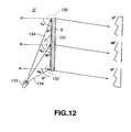
- the illumination light 134 is applied from the light source 133 to the upper, middle and lower parts 130, 131 and 132 of a holographic stereogram 6 at different incidence angles, as is illustrated in FIG. 12.
- the illumination light 134 emitted from the light source 133 is not applied to the holographic stereogram 6 at an ideal incidence angle.
- the front side of the optical member 7 consists of parallel triangular prisms that have incidence surfaces inclined at different angles in accordance with the incidence angles at which the illumination light is applied to the upper, middle and lower parts 130, 131 and 132 of the holographic stereogram 6.
- the illumination light 134 may define an angle of 30° with respect to the middle part 131 of the stereogram 6.
- the angle A between the light 134 and the upper part 130 of the stereogram 6 is smaller than 30°
- the angle B between the light 134 and the lower part 132 is greater than 30°.
- the incidence surfaces of the triangular prisms on the front side of the optical member 7' are inclined at different angles that accord with the different incidence angles at which the light 134 is applied to the upper, middle and lower parts 130, 131 and 132 of the stereogram 6.
- the third embodiment can reproduce 3-dimensional image of high quality in many cases.
- the fourth embodiment of this invention is an image-reproducing apparatus, too.
- a holographic stereogram and an optical member both being identical to those used in the third embodiment, are bent into a hollow cylindrical holographic stereogram of edge-lit type. This stereogram is used to reproduce a 3-dimensional image.
- the fourth embodiment it is unnecessary to convert the illumination light emitted from the light source to parallel light that is to be applied to the holographic stereogram at an incidence angle of, for example, 60°. Therefore, there is no need to use such a conical prism as is used in the second embodiment.
- the fourth embodiment can yet form a 3-dimensional image that looks as if a real body were existing in the hollow cylinder.
- an optical member is bonded to a holographic stereogram.
- the optical member may be bonded to a hologram, so that a 3-dimensional image may be reproduced from the hologram.
- the image-reproducing apparatus is not limited to one having a hologram or a holographic stereogram that records a 3-dimensional image. Rather, the present invention can be applied to one having a hologram or a holographic stereogram that records a 2-dimensional image.
Landscapes
- Physics & Mathematics (AREA)
- General Physics & Mathematics (AREA)
- Optics & Photonics (AREA)
- Holo Graphy (AREA)
- Testing, Inspecting, Measuring Of Stereoscopic Televisions And Televisions (AREA)
Claims (18)
- Bildwiedergabevorrichtung (5, 140) zur Wiedergabe eines Bildes von einem Hologramm oder einem holografischen Stereogramm (6, 141), in welchem entweder zweidimensionale Bilddaten oder dreidimensionale Bilddaten aufgezeichnet sind, wobei die Bildwiedergabevorrichtung aus einem mit dem Hologramm oder holografischen Stereogramm (6, 141) verbundenen optischen Glied (7, 147) besteht,
wobei das optische Glied (7, 147) eine Vorderseite (7a) und eine der Vorderseite gegenüberliegende Rückseite (7b) aufweist
und wobei die Rückseite (7b) des optischen Gliedes (7, 147) mit dem Hologramm oder dem holografischen Stereogramm (6, 141) verbunden ist,
dadurch gekennzeichnet,
dass die Vorderseite (7a) des optischen Gliedes (7, 147) aus Prismen besteht, deren jedes eine Einfallsfläche (8) und eine geneigte Fläche (23) aufweist,
dass die Einfallsflächen (8) derart angeordnet sind, dass in dem Fall, dass Beleuchtungslicht (9) auf die betreffende Vorderseite (7a) des optischen Gliedes (7) in der Richtung von der Außenseite des optischen Gliedes zu dessen Innenseite abgegeben wird und durch die betreffenden Einfallsflächen (8) gelangt, das betreffende Beleuchtungslicht an einer Grenzfläche (22) zwischen dem optischen Glied (7, 147) und dem Hologramm oder holografischen Stereogramm (6, 141) innerhalb eines bestimmten Einfallswinkelbereichs ankommt, um dadurch ein zwei- oder dreidimensionales Bild von dem Hologramm oder holografischen Stereogramm wiederzugeben. - Bildwiedergabevorrichtung nach Anspruch 1, wobei der bestimmte Einfallswinkelbereich von 60° bis 85° in Bezug auf eine Senkrechte zu der Grenzfläche beträgt.
- Bildwiedergabevorrichtung nach Anspruch 1, wobei die geneigten Flächen (23) der Prismen zu den Einfallsflächen (8) unter rechten Winkeln und zu der Grenzfläche (22) unter demselben Winkel geneigt sind.
- Bildwiedergabevorrichtung nach Anspruch 1, wobei die geneigten Flächen (23) der Prismen zu den Einfallsflächen (8) unter rechten Winkeln und zu der Grenzfläche (22) unter verschiedenen Winkeln geneigt sind.
- Bildwiedergabevorrichtung nach Anspruch 1, wobei die Einfallsflächen in regelmäßigen Intervallen angeordnet sind.
- Bildwiedergabevorrichtung nach Anspruch 5, wobei die regelmäßigen Intervalle höchstens 0,5mm betragen.
- Bildwiedergabevorrichtung nach einem der vorhergehenden Ansprüche, wobei das Hologramm oder holografische Stereogramm (6; 141) und das damit verbundene optische Glied (7; 143) derart gebogen sind, dass ein Hohlzylinder (91) gebildet ist, dessen Innenfläche durch die genannte Vorderseite des optischen Gliedes festgelegt ist, wobei in dem Fall, dass Beleuchtungslicht an eine Innenfläche des Hohlzylinders abgegeben wird, ein zwei- oder dreidimensionales Bild von dem Hologramm oder holografischen Stereogramm wiedergegeben wird.
- Bildwiedergabeverfahren zur Wiedergabe eines Bildes von einem Hologramm oder holografischen Stereogramm (6), in welchem entweder zweidimensionale Bilddaten oder dreidimensionale Bilddaten aufgezeichnet sind, umfassend die Schritte des Bereitstellens eines optischen Gliedes (1) mit einer Vorderseite (7a) und einer der Vorderseite gegenüberliegenden Rückseite (7b) und des Verbindens der Rückseite (7b) des optischen Gliedes (1) mit dem Hologramm oder holografischen Stereogramm,
dadurch gekennzeichnet,
dass der Bereitstellungsschritt die Bereitstellung eines optischen Gliedes (1) umfasst, welches eine Vorderseite (7a) aufweist, die aus Prismen besteht, deren jedes eine Einfallsfläche (8) und eine geneigte Fläche (23) aufweist,
und dass ferner der Schritt der Abgabe von Beleuchtungslicht (9) an die Vorderseite (7a) des optischen Gliedes in der Richtung von der Außenseite des optischen Gliedes zu dessen Innenseite vorgesehen ist, derart, dass dadurch ein zwei-oder dreidimensionales Bild von dem Hologramm oder holografischen Stereogramm wiedergegeben wird. - Bildwiedergabeverfahren nach Anspruch 8, wobei das Beleuchtungslicht (9) unter rechten Winkeln zu den Einfallsflächen abgegeben wird.
- Bildwiedergabeverfahren nach Anspruch 9, wobei das Beleuchtungslicht (9) an eine Grenzfläche zwischen dem optischen Glied (7) und dem Hologramm oder holografischen Stereogramm (6) unter einem festliegenden Einfallswinkel abgegeben wird, der in einen bestimmten Bereich fällt, derart, dass dadurch eine Oberflächenreflexion des Beleuchtungslichts an der Grenzfläche unterdrückt wird.
- Bildwiedergabeverfahren nach Anspruch 10, wobei der festliegende Einfallswinkelbereich von 60° bis 85° in Bezug auf eine Senkrechte zu der Grenzfläche reicht.
- Bildwiedergabeverfahren nach Anspruch 10, wobei die geneigten Flächen (23) der Prismen zu den Einfallsflächen (8) unter rechten Winkeln und zu der Grenzfläche unter demselben Winkel geneigt sind, der gleich dem festliegenden Einfallswinkel ist.
- Bildwiedergabeverfahren nach einem der Ansprüche 8 bis 12, wobei das Hologramm oder holografische Stereogramm (6) und das damit verbundene optische Glied (7) unter Bildung eines Hohlzylinders (91) gebogen werden bzw. sind, dessen Innenfläche durch die genannte Vorderseite (7a) des optischen Gliedes festgelegt ist,
und wobei das Beleuchtungslicht an die Innenfläche des Hohlzylinders abgegeben wird, derart, dass dadurch ein zwei- oder dreidimensionales Bild von dem Hologramm oder holografischen Stereogramm wiedergegeben wird. - Bildwiedergabeverfahren nach Anspruch 10, wobei das Beleuchtungslicht (9) an eine Grenzfläche zwischen dem optischen Glied (7) und dem Hologramm oder holografischen Stereogramm (6) unter verschiedenen Einfallswinkeln abgegeben wird, die in einen bestimmten Bereich fallen, derart, dass dadurch eine Oberflächenreflexion des Beleuchtungslichts an der Grenzfläche unterdrückt wird.
- Bildwiedergabeverfahren nach Anspruch 14, wobei die verschiedenen Einfallswinkelbereiche von 60° bis 85° in Bezug auf eine Senkrechte zu der Grenzfläche reichen.
- Bildwiedergabeverfahren nach Anspruch 15, wobei die geneigten Flächen (23) der Prismen zu den Einfallsflächen unter rechten Winkeln und zu der Grenzfläche unter verschiedenen Winkeln geneigt sind.
- Bildwiedergabeverfahren nach einem der Ansprüche 9 bis 16, wobei die Einfallsflächen (8) an parallelen Prismen vorgesehen und in regelmäßigen Intervallen angeordnet sind.
- Bildwiedergabeverfahren nach Anspruch 17, wobei die regelmäßigen Intervalle höchstens 0,5mm betragen.
Applications Claiming Priority (2)
| Application Number | Priority Date | Filing Date | Title |
|---|---|---|---|
| JP2000219504A JP4442000B2 (ja) | 2000-07-19 | 2000-07-19 | 画像再生装置及び画像再生方法 |
| JP2000219504 | 2000-07-19 |
Publications (3)
| Publication Number | Publication Date |
|---|---|
| EP1174751A2 EP1174751A2 (de) | 2002-01-23 |
| EP1174751A3 EP1174751A3 (de) | 2003-10-29 |
| EP1174751B1 true EP1174751B1 (de) | 2006-08-30 |
Family
ID=18714281
Family Applications (1)
| Application Number | Title | Priority Date | Filing Date |
|---|---|---|---|
| EP01401933A Expired - Lifetime EP1174751B1 (de) | 2000-07-19 | 2001-07-19 | Holografisches Bildwiedergabe-Gerät und Bildwiedergabeverfahren |
Country Status (6)
| Country | Link |
|---|---|
| US (5) | US6738170B2 (de) |
| EP (1) | EP1174751B1 (de) |
| JP (1) | JP4442000B2 (de) |
| KR (1) | KR100855287B1 (de) |
| CN (1) | CN100435043C (de) |
| DE (1) | DE60122632T2 (de) |
Cited By (1)
| Publication number | Priority date | Publication date | Assignee | Title |
|---|---|---|---|---|
| RU181211U1 (ru) * | 2017-12-01 | 2018-07-06 | Федеральное государственное бюджетное учреждение науки Институт автоматики и электрометрии Сибирского отделения Российской академии наук (ИАиЭ СО РАН) | Устройство записи и тестирования голографических объёмных отражательных решёток |
Families Citing this family (15)
| Publication number | Priority date | Publication date | Assignee | Title |
|---|---|---|---|---|
| JP4442000B2 (ja) * | 2000-07-19 | 2010-03-31 | ソニー株式会社 | 画像再生装置及び画像再生方法 |
| JP4075418B2 (ja) * | 2002-03-15 | 2008-04-16 | ソニー株式会社 | 画像処理装置及び画像処理方法、印刷物製造装置及び印刷物製造方法、並びに印刷物製造システム |
| US7245408B1 (en) * | 2003-10-10 | 2007-07-17 | Zebra Imaging, Inc. | Systems and methods for producing wide field-of-view holographic displays |
| WO2006034054A1 (en) * | 2004-09-16 | 2006-03-30 | Belashchenko Vladimir E | Deposition system, method and materials for composite coatings |
| US8373698B2 (en) * | 2007-05-10 | 2013-02-12 | International Business Machines Corporation | Holographic enterprise network |
| US8294705B2 (en) * | 2007-05-10 | 2012-10-23 | International Business Machines Corporation | Virtual network operations center |
| US7839401B2 (en) * | 2007-05-10 | 2010-11-23 | International Business Machines Corporation | Management of enterprise systems and applications using three-dimensional visualization technology |
| US8259099B2 (en) * | 2007-05-17 | 2012-09-04 | International Business Machines Corporation | Use of three-dimensional data center to support servicing external operations |
| US20080288220A1 (en) * | 2007-05-17 | 2008-11-20 | Dillenberger Donna N | Use of a three-dimensional (3d) data center to share service operations |
| CN103558689B (zh) * | 2008-07-10 | 2017-09-26 | 实景成像有限公司 | 用户接口以及用于实施浮于空中用户接口的方法 |
| US8386930B2 (en) * | 2009-06-05 | 2013-02-26 | International Business Machines Corporation | Contextual data center management utilizing a virtual environment |
| US8908249B2 (en) * | 2010-08-13 | 2014-12-09 | Claudelli Productions, Inc | Wide angle hologram device illuminated with a near field source and method for manufacturing same |
| KR102250871B1 (ko) * | 2014-04-11 | 2021-05-11 | 한국전자기술연구원 | 원통형 또는 구형 홀로그래픽 스테레오그램을 위한 3d 콘텐츠 생성방법 및 장치 |
| CN106940486B (zh) * | 2017-04-25 | 2022-06-24 | 京东方科技集团股份有限公司 | 一种显示装置及其显示方法 |
| US20210318658A1 (en) * | 2017-05-29 | 2021-10-14 | Artience Lab Inc. | Optical deflection device, image display device, signal device, image recording medium, and image reproduction method |
Family Cites Families (19)
| Publication number | Priority date | Publication date | Assignee | Title |
|---|---|---|---|---|
| JPS62250472A (ja) * | 1986-04-23 | 1987-10-31 | Mazda Motor Corp | ホログラム再生装置 |
| US5619586A (en) * | 1990-12-20 | 1997-04-08 | Thorn Emi Plc | Method and apparatus for producing a directly viewable image of a fingerprint |
| JPH05224018A (ja) * | 1991-07-30 | 1993-09-03 | Nippondenso Co Ltd | 導光装置 |
| US5455693A (en) * | 1992-09-24 | 1995-10-03 | Hughes Aircraft Company | Display hologram |
| US5504593A (en) * | 1992-12-16 | 1996-04-02 | Dai Nippon Printing Co., Ltd. | Continuous and uniform hologram recording method and uniformly recorded hologram |
| US5341230A (en) * | 1992-12-22 | 1994-08-23 | Hughes Aircraft Company | Waveguide holographic telltale display |
| WO1995004294A2 (en) * | 1993-07-21 | 1995-02-09 | Imedge Technology, Inc. | Holograms and light panels |
| JPH08286631A (ja) * | 1995-04-14 | 1996-11-01 | Dainippon Printing Co Ltd | ハザードシート |
| JP3539790B2 (ja) * | 1995-04-26 | 2004-07-07 | 凸版印刷株式会社 | ディスプレイ装置 |
| US5698906A (en) * | 1995-09-29 | 1997-12-16 | Hughes Electronics | Remotely-controlled locking systems employing a holographic display |
| US5742411A (en) * | 1996-04-23 | 1998-04-21 | Advanced Deposition Technologies, Inc. | Security hologram with covert messaging |
| JP4076240B2 (ja) * | 1996-11-06 | 2008-04-16 | 大日本印刷株式会社 | 複合ホログラム |
| JP3709648B2 (ja) * | 1997-03-11 | 2005-10-26 | ソニー株式会社 | 画像再生方法及び画像再生装置 |
| US6019586A (en) * | 1998-01-20 | 2000-02-01 | Sunny King Machinery Co., Ltd. | Gradationally contracted screw compression equipment |
| JP2000048392A (ja) * | 1998-07-27 | 2000-02-18 | Mitsubishi Electric Corp | 光ピックアップ装置 |
| JP4437566B2 (ja) * | 1998-11-26 | 2010-03-24 | 大日本印刷株式会社 | 照明付きホログラム表示装置 |
| US6118589A (en) * | 1999-01-06 | 2000-09-12 | Compaq Computer Corporation | Apparatus, method and system for 3-D and panoramic imaging |
| AU2290301A (en) | 1999-12-23 | 2001-07-03 | Neurok, Llc | System and method for the manufacture of a universal reflective-transmissive display |
| JP4442000B2 (ja) * | 2000-07-19 | 2010-03-31 | ソニー株式会社 | 画像再生装置及び画像再生方法 |
-
2000
- 2000-07-19 JP JP2000219504A patent/JP4442000B2/ja not_active Expired - Fee Related
-
2001
- 2001-07-13 KR KR1020010042432A patent/KR100855287B1/ko not_active Expired - Fee Related
- 2001-07-18 US US09/906,672 patent/US6738170B2/en not_active Expired - Fee Related
- 2001-07-19 CN CNB011259965A patent/CN100435043C/zh not_active Expired - Fee Related
- 2001-07-19 EP EP01401933A patent/EP1174751B1/de not_active Expired - Lifetime
- 2001-07-19 DE DE60122632T patent/DE60122632T2/de not_active Expired - Lifetime
-
2003
- 2003-11-04 US US10/699,701 patent/US6903852B2/en not_active Expired - Fee Related
-
2005
- 2005-01-24 US US11/039,929 patent/US6977761B2/en not_active Expired - Fee Related
- 2005-03-21 US US11/084,019 patent/US6980338B2/en not_active Expired - Fee Related
- 2005-03-21 US US11/084,025 patent/US6975440B2/en not_active Expired - Fee Related
Cited By (1)
| Publication number | Priority date | Publication date | Assignee | Title |
|---|---|---|---|---|
| RU181211U1 (ru) * | 2017-12-01 | 2018-07-06 | Федеральное государственное бюджетное учреждение науки Институт автоматики и электрометрии Сибирского отделения Российской академии наук (ИАиЭ СО РАН) | Устройство записи и тестирования голографических объёмных отражательных решёток |
Also Published As
| Publication number | Publication date |
|---|---|
| CN1334494A (zh) | 2002-02-06 |
| US6975440B2 (en) | 2005-12-13 |
| CN100435043C (zh) | 2008-11-19 |
| US20050162720A1 (en) | 2005-07-28 |
| US6980338B2 (en) | 2005-12-27 |
| JP4442000B2 (ja) | 2010-03-31 |
| EP1174751A2 (de) | 2002-01-23 |
| JP2002040911A (ja) | 2002-02-08 |
| US20040120021A1 (en) | 2004-06-24 |
| EP1174751A3 (de) | 2003-10-29 |
| US6738170B2 (en) | 2004-05-18 |
| US6977761B2 (en) | 2005-12-20 |
| US6903852B2 (en) | 2005-06-07 |
| DE60122632T2 (de) | 2007-08-30 |
| US20020027680A1 (en) | 2002-03-07 |
| DE60122632D1 (de) | 2006-10-12 |
| KR20020007217A (ko) | 2002-01-26 |
| US20050122553A1 (en) | 2005-06-09 |
| KR100855287B1 (ko) | 2008-08-29 |
| US20050162721A1 (en) | 2005-07-28 |
Similar Documents
| Publication | Publication Date | Title |
|---|---|---|
| CN112415747B (zh) | 导光板、导光板的制造装置、导光板的制造方法、以及使用该导光板的影像显示装置 | |
| US6977761B2 (en) | Image-reproducing apparatus and image-reproducing method | |
| KR101328970B1 (ko) | 영상 형성 방법 및 영상 투사 장치 | |
| JP2000267041A (ja) | 頭部搭載型カラー映像投影装置、カラーホログラム光学素子、およびカラーホログラム光学素子の製造方法 | |
| US20130120816A1 (en) | Thin flat type convergence lens | |
| KR100610518B1 (ko) | 화상 데이터 발생 장치 | |
| US7317564B2 (en) | Replay optics for holographic displays | |
| US6747770B2 (en) | Holographic stereogram exposure apparatus, method thereof, and holographic stereogram generation system | |
| US6101161A (en) | Volume holographic data storage system incorporating therein a cylindrical storage medium | |
| US6870651B2 (en) | Apparatus and method for generating a dynamic image | |
| US20070019266A1 (en) | Holographic stereogram creation device and its method | |
| JP4479374B2 (ja) | 画像表示装置、画像記録用媒体および画像記録方法 | |
| US6181665B1 (en) | Volume holographic data storage system | |
| EP1363173A1 (de) | Hologrammvervielfältigungseinrichtung und verfahren | |
| JP4288722B2 (ja) | 画像データ作成装置及び作成方法、画像データ変換装置及び変換方法、ホログラフィックステレオグラム作成装置及び作成方法、記録媒体並びにデータ伝送方法 | |
| EP0969338A1 (de) | Vorrichtung und Verfahren zur Erzeugung eines holographischen Stereogramms | |
| WO2022249597A1 (ja) | 画像表示装置及び導光光学系 | |
| KR101980353B1 (ko) | 박막 평판형 수렴 렌즈 | |
| JP2003216009A (ja) | 画像再生装置及びホログラム部材 | |
| JPH0784208A (ja) | 画像表示装置 | |
| JP3274811B2 (ja) | 三次元像投写装置 | |
| KR100275278B1 (ko) | 볼륨 홀로그래픽 디지탈 저장 시스템 | |
| CN117991577A (zh) | 一种全息投影显示设备和智能音箱 | |
| CN1242530A (zh) | 全息立体图生成装置和方法 | |
| JP2002304110A (ja) | 画像再生装置 |
Legal Events
| Date | Code | Title | Description |
|---|---|---|---|
| PUAI | Public reference made under article 153(3) epc to a published international application that has entered the european phase |
Free format text: ORIGINAL CODE: 0009012 |
|
| AK | Designated contracting states |
Kind code of ref document: A2 Designated state(s): AT BE CH CY DE DK ES FI FR GB GR IE IT LI LU MC NL PT SE TR |
|
| AX | Request for extension of the european patent |
Free format text: AL;LT;LV;MK;RO;SI |
|
| PUAL | Search report despatched |
Free format text: ORIGINAL CODE: 0009013 |
|
| AK | Designated contracting states |
Kind code of ref document: A3 Designated state(s): AT BE CH CY DE DK ES FI FR GB GR IE IT LI LU MC NL PT SE TR |
|
| AX | Request for extension of the european patent |
Extension state: AL LT LV MK RO SI |
|
| 17P | Request for examination filed |
Effective date: 20040429 |
|
| AKX | Designation fees paid |
Designated state(s): DE FR GB |
|
| 17Q | First examination report despatched |
Effective date: 20040708 |
|
| GRAP | Despatch of communication of intention to grant a patent |
Free format text: ORIGINAL CODE: EPIDOSNIGR1 |
|
| GRAS | Grant fee paid |
Free format text: ORIGINAL CODE: EPIDOSNIGR3 |
|
| GRAA | (expected) grant |
Free format text: ORIGINAL CODE: 0009210 |
|
| AK | Designated contracting states |
Kind code of ref document: B1 Designated state(s): DE FR GB |
|
| REG | Reference to a national code |
Ref country code: GB Ref legal event code: FG4D |
|
| REF | Corresponds to: |
Ref document number: 60122632 Country of ref document: DE Date of ref document: 20061012 Kind code of ref document: P |
|
| ET | Fr: translation filed | ||
| PLBE | No opposition filed within time limit |
Free format text: ORIGINAL CODE: 0009261 |
|
| STAA | Information on the status of an ep patent application or granted ep patent |
Free format text: STATUS: NO OPPOSITION FILED WITHIN TIME LIMIT |
|
| 26N | No opposition filed |
Effective date: 20070531 |
|
| PGFP | Annual fee paid to national office [announced via postgrant information from national office to epo] |
Ref country code: DE Payment date: 20140721 Year of fee payment: 14 |
|
| PGFP | Annual fee paid to national office [announced via postgrant information from national office to epo] |
Ref country code: GB Payment date: 20140721 Year of fee payment: 14 Ref country code: FR Payment date: 20140721 Year of fee payment: 14 |
|
| REG | Reference to a national code |
Ref country code: DE Ref legal event code: R119 Ref document number: 60122632 Country of ref document: DE |
|
| GBPC | Gb: european patent ceased through non-payment of renewal fee |
Effective date: 20150719 |
|
| PG25 | Lapsed in a contracting state [announced via postgrant information from national office to epo] |
Ref country code: GB Free format text: LAPSE BECAUSE OF NON-PAYMENT OF DUE FEES Effective date: 20150719 Ref country code: DE Free format text: LAPSE BECAUSE OF NON-PAYMENT OF DUE FEES Effective date: 20160202 |
|
| REG | Reference to a national code |
Ref country code: FR Ref legal event code: ST Effective date: 20160331 |
|
| PG25 | Lapsed in a contracting state [announced via postgrant information from national office to epo] |
Ref country code: FR Free format text: LAPSE BECAUSE OF NON-PAYMENT OF DUE FEES Effective date: 20150731 |