EP1174695A1 - Rolle zur Messung der Ebenheit - Google Patents
Rolle zur Messung der Ebenheit Download PDFInfo
- Publication number
- EP1174695A1 EP1174695A1 EP01401925A EP01401925A EP1174695A1 EP 1174695 A1 EP1174695 A1 EP 1174695A1 EP 01401925 A EP01401925 A EP 01401925A EP 01401925 A EP01401925 A EP 01401925A EP 1174695 A1 EP1174695 A1 EP 1174695A1
- Authority
- EP
- European Patent Office
- Prior art keywords
- face
- cover
- housing
- sleeve
- roller according
- Prior art date
- Legal status (The legal status is an assumption and is not a legal conclusion. Google has not performed a legal analysis and makes no representation as to the accuracy of the status listed.)
- Granted
Links
Images

Classifications
-
- G—PHYSICS
- G01—MEASURING; TESTING
- G01B—MEASURING LENGTH, THICKNESS OR SIMILAR LINEAR DIMENSIONS; MEASURING ANGLES; MEASURING AREAS; MEASURING IRREGULARITIES OF SURFACES OR CONTOURS
- G01B5/00—Measuring arrangements characterised by the use of mechanical techniques
- G01B5/28—Measuring arrangements characterised by the use of mechanical techniques for measuring roughness or irregularity of surfaces
-
- G—PHYSICS
- G01—MEASURING; TESTING
- G01B—MEASURING LENGTH, THICKNESS OR SIMILAR LINEAR DIMENSIONS; MEASURING ANGLES; MEASURING AREAS; MEASURING IRREGULARITIES OF SURFACES OR CONTOURS
- G01B7/00—Measuring arrangements characterised by the use of electric or magnetic techniques
- G01B7/34—Measuring arrangements characterised by the use of electric or magnetic techniques for measuring roughness or irregularity of surfaces
- G01B7/345—Measuring arrangements characterised by the use of electric or magnetic techniques for measuring roughness or irregularity of surfaces for measuring evenness
-
- B—PERFORMING OPERATIONS; TRANSPORTING
- B21—MECHANICAL METAL-WORKING WITHOUT ESSENTIALLY REMOVING MATERIAL; PUNCHING METAL
- B21B—ROLLING OF METAL
- B21B38/00—Methods or devices for measuring, detecting or monitoring specially adapted for metal-rolling mills, e.g. position detection, inspection of the product
- B21B38/02—Methods or devices for measuring, detecting or monitoring specially adapted for metal-rolling mills, e.g. position detection, inspection of the product for measuring flatness or profile of strips
-
- G—PHYSICS
- G01—MEASURING; TESTING
- G01B—MEASURING LENGTH, THICKNESS OR SIMILAR LINEAR DIMENSIONS; MEASURING ANGLES; MEASURING AREAS; MEASURING IRREGULARITIES OF SURFACES OR CONTOURS
- G01B7/00—Measuring arrangements characterised by the use of electric or magnetic techniques
- G01B7/28—Measuring arrangements characterised by the use of electric or magnetic techniques for measuring contours or curvatures
- G01B7/287—Measuring arrangements characterised by the use of electric or magnetic techniques for measuring contours or curvatures using a plurality of fixed, simultaneously operating transducers
-
- G—PHYSICS
- G01—MEASURING; TESTING
- G01L—MEASURING FORCE, STRESS, TORQUE, WORK, MECHANICAL POWER, MECHANICAL EFFICIENCY, OR FLUID PRESSURE
- G01L5/00—Apparatus for, or methods of, measuring force, work, mechanical power, or torque, specially adapted for specific purposes
- G01L5/04—Apparatus for, or methods of, measuring force, work, mechanical power, or torque, specially adapted for specific purposes for measuring tension in flexible members, e.g. ropes, cables, wires, threads, belts or bands
- G01L5/045—Apparatus for, or methods of, measuring force, work, mechanical power, or torque, specially adapted for specific purposes for measuring tension in flexible members, e.g. ropes, cables, wires, threads, belts or bands for measuring the tension across the width of a band-shaped flexible member
Definitions
- the subject of the invention is a measuring roller, in the process, of the distribution of stresses applied on a strip, specially usable to detect flatness defects on a metal sheet.
- a support cylinder including an envelope deformable rotatably mounted around a fixed shaft and resting on it by a plurality of cylinders which can be adjusted in position and pressure.
- the tape is passed over a measuring device, placed downstream of the rolling mill, and sensitive to variations, on the width of the strip, the tensile force applied to it.
- Such a measuring device usually consists of a deflector roller comprising a cylindrical body rotatably mounted around a axis perpendicular to the longitudinal direction of travel of the strip which is applied under tension to an angular sector of this roller.
- a series of sensors distributed on the cylindrical external face of the roller to measure variations in local application pressure Of the band usually these detectors are regularly discarded of others and distributed over the entire length of the roll, the strip can thus be divided into a series of adjacent areas of width corresponding to the transverse spacing between the sensors.
- the sensors are advantageously angularly offset from one zone to the next.
- the deflector roller is made up of segments juxtaposed annulars each comprising at least one force sensor placed in a housing formed in the thickness of the segment and consisting of a piezoelectric transducer interposed between the bottom of the housing and a room protection which closes the housing to the outside.
- the deflector roller consists of a tubular body in which a plurality of radial bores are drilled, each forming a housing for a cylindrical housing whose bottom consists of a thin wall which is tangentially connects to the outer face of the tubular body.
- a sensor magnetostriction type, is applied to the internal face of this wall.
- each measurement area is associated with a force sensor to which the pressure applied by the strip is transmitted by the protective wall.
- the inherent resistance of this wall interposed between the sensor and the tape may affect the pressure measurement hard to appreciate.
- the measurement can also be disturbed by external influences resulting for example from expansion of the roll due to the temperature of the strip or its deformation under the effect loads applied which may cause the wall to jam protection.
- the deflector roller includes a body central consisting of a tubular wall thick enough to give resistance necessary and on which is threaded a continuous thin envelope which is, generally applied by shrinking, the sensors being placed in bores made in the central body and closed outwards by the part corresponding of the thin envelope.
- This part of the envelope forms a sensitive zone and it can be considered that it behaves like a thin plate, normally circular, and embedded on its periphery, this plate being subjected to a uniform pressure.
- the deflection is measured by comparison positions, respectively empty and laden, of the movable element of the feeler which rests on the center of the plate. It is thus possible, by comparing the measurements made by the different sensors, to determine variations in tensile stress in adjacent adjacent areas across the width of the strip.
- the object of the invention is to remedy these drawbacks by means of a new arrangement to simplify the production of the roll and maintenance operations and giving, in particular, the possibility of intervening punctually on one or other of the sensors without dismantling the assembly.
- the invention therefore relates, in general, to a roll of measurement of the distribution of stresses on a strip moving along a longitudinal direction and applied to said roller, the latter comprising a tubular body rotatably mounted about an axis perpendicular to the direction of scrolling and carrying a plurality of measuring members sensitive to a local application pressure of the tape and each mounted in a housing bounded by a lateral face and closed, towards the outside, by a wall having a cylindrical outer face with the same radius of curvature as the outer face of the roller, each measuring member being a displacement sensor of the type probe comprising a movable element mounted to slide radially on a fixed element and applied towards the outside on the internal face of the wall of closing of the accommodation.
- each housing of a sensor is individually closed by a hollow piece in the form of a cover having a bottom consisting of an elastically deformable thin plate secured to a socket-shaped peripheral part limited by two lateral faces respectively internal and external, the external face having a profile, in section transverse, identical to that of the lateral face of the housing, so that the cover fits without play in said housing by taking support, by a end of the sleeve, on a part of the tubular body, in a position for which the external face of the bottom is in the extension of the face external of the roller, the side faces facing the housing and the bush, being applied one on the other over a sufficient height so that said socket constitutes a means of embedding the thin plate capable of withstand the bending moments resulting from the pressure applied by the strip, without risk of detachment along the joint between the external face of the cover and the external face of the tubular body.
- the internal lateral face of the sleeve of connection is connected, by a rounded fillet, to the internal face of the deformable plate on which the movable element of the probe bears.
- each cover of a housing is associated with a permanent means of maintaining the application one on the other side faces facing the housing and the socket.
- this holding means is consisting of a stop piece placed in the housing and projecting inside the cover sleeve, said abutment part being limited by a side face having a profile identical, in cross section, to that of the internal lateral face of the sleeve, so as to provide space between said piece of stop and the side face of the housing, an annular space in which the cover sleeve fits without play, inwards and outwards.
- the stop piece is limited, outwards, by a front end face, spaced from the face internal of the thin wall deformable by a slight clearance corresponding to a maximum deformation in the elastic range of the thin wall under the effect of a local pressure of application of the strip, and on which comes supports said thin wall in the event of excessive pressure, said front face being pierced with a through hole with clearance of the movable element of the probe.
- the abutment piece can be provided, at the bottom of the housing, of an enlarged part forming a peripheral rim on which comes support the cover mounting sleeve, in the position pressed in of it for which the outer face of the thin wall is in the extension of the external face of the tubular body, the internal lateral face of the sleeve being bordered by a groove having an annular bottom on which comes support the peripheral edge of the stopper piece.
- the cover mounting socket is supported on the bottom of the housing at level of its internal lateral face, which promotes the embedding effect.
- the cover can be simply fitted by force in the annular space between the abutment piece and the lateral face of the housing.
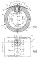
- Figure 1 is a cross-sectional view of a roll of measure according to the invention.
- Figure 2 is a longitudinal sectional view, along line II-II of the figure 1, of the assembly of a measurement sensor.
- Figure 3 is a top view of part of the roller, with removal of the sensor cover.
- Figure 4 shows, in cross section, all the parts of the sensor before mounting.
- FIG. 5 is a detail view, on an enlarged scale, of an area of measured.
- a roller flatness measuring device 1 which, as usual, constitutes a roller deflector for a metal strip (M) which runs in one direction longitudinal perpendicular to the axis of rotation 10 of the roller and is wound on an angular sector A thereof.
- the deflector roller according to the invention is of the sensor type. displacement which is the subject of European patent EP-0.028.191 of the same society. It is therefore equipped with a plurality of sensors which are separated from one of the other transversely and angularly. As stated in the patent previous EP-0.028.191, the different sensors are advantageously distributed on a helical curve that wraps around the outside of the roller deflector.
- Each displacement sensor includes a deformable wall forming a zone of width (I) sensitive to the pressure applied by a zone corresponding elementary of the band. Two adjacent sensors C1, C2 are therefore shifted, in the transverse direction, by the same distance (I).
- the roller deflector 1 is equipped with four series of displacement sensors centered on two perpendicular diametrical planes.
- the pitch (L) of the propeller must therefore be four times the width (I) of a sensitive area to cover the entire width of the tape without loss of information. However, it can also be reduced to increase the resolution of the roller.
- signal processing means make it possible to differentiate the measurements made by the sensors.
- each sensor is therefore associated with a zone sensitive, of width (I) formed on the surface of the roller and the deformations are measured by a probe 2.
- the roller 1 comprises a tubular body 12 consisting of a wall having a thickness (e) sufficient to withstand the resulting bending forces of the application of the strip under tension.
- Each probe 2 is mounted on the center of a housing 3 comprising a bore 31 formed radially in the tubular body 12 and which opens outwardly into a counterbore 32 centered on the axis 30 of the bore 31 and formed over part of the thickness (e) of the roller.
- This counterbore 32 is therefore limited by a flat annular bottom 33 perpendicular to the axis 30 of the bore 31 and a lateral wall 34 orthogonal at the bottom 33.
- the counterbore 32 is circular and the side wall 34 has a cylindrical profile centered on the axis 30 and having a diameter (d) greater than the width (I) of an elementary zone for measuring the strip.
- Each probe 2 comprises a fixed element 21 which is threaded with clearance in the bore 31 of the tubular body 12 and in which is slidably mounted, axially, a movable element 22 which opens outwards into the counterbore 3, when the probe 2 is fixed on the roller.
- the probes of the same series are mounted on a bar 4 extending transversely across the width of the roll and applied to the inner face 13 of the tubular body 12, the bar 2 being provided with a face cylindrical application of conjugate profile.
- the invention makes it possible to remove the envelope thin fretted which, in the preceding provisions, entirely covered the tubular body 12.
- the strip M is applied directly on the cylindrical external face 11 of the tubular body 12 and each counterbore 3 in which a probe 2 is placed opens onto this external face 11, by an orifice 35 which is closed by a cover 5 having an external face cylindrical 51 with the same radius of curvature as the external face 11 of the body tubular and which is placed in the extension thereof to restore the continuity of the roller surface, when the cover 5 is pressed into the counterbore 32.
- each cover 5 constitutes a hollow cap-shaped part comprising a bottom 50 consisting of a thin wall having an outer face 51 and an inner face 52 and a lateral part 53 consisting of a cylindrical sleeve having two faces lateral, respectively external 54 and internal 55, and one end face 56.
- the external lateral face 54 of the cover 5 has a diameter (d) exactly equal to the diameter of the lateral face 34 of the counterbore 32 so that that the sleeve 53 of the cover 5 fits without play in the counterbore 32 until that its end 56 is supported on the bottom 33 of the counterbore in a depressed position for which the outer face 51 of the cover 5 is located exactly in line with the external face 11 of the tubular body 12.
- the two opposite side faces, 54 respectively of the cover 5 and 34 of the counterbore 32 are threaded one on the other.
- the dimensions of the socket 53 are determined so that the thin wall 50 behaves like a circular plate embedded by its periphery on the socket 53 whose no part can turn under the effect of the moments resulting from the pressure applied to the thin wall 50 and which thus forms a mounting base device of the deformable wall 50.
- the movable element 22 of the probe 2 is applied on the internal face 52 of the thin wall 50 and therefore detects exactly the deformations thereof.
- the deflection (f) measured by the probe is proportional to the pressure (p) itself proportional to the traction applied to the strip in the area corresponding to it.
- the height h2 and the thickness e1 of the sleeve 53 can be determined so that, after fitting the cover 5 in the housing 32, the socket 53 constitutes by itself a fitting means thin plate device 50.
- the socket 53 is kept fitted without clearance, not only outwards via the lateral face 34 of the counterbore but also inwards, by a stop piece 6 fixed in the center of the housing 3 of probe 2.
- This stop piece 6 is hat-shaped with one end 61 forming an annular flat face for bearing on an internal part of the bottom annular 33 of the counterbore 32 and a cylindrical side face 62 having a diameter (d ') identical to that of the internal lateral face 55 of the socket 53.
- the stop piece 6 therefore extends in protrusion in the center of the housing formed by the counterbore 32 leaving it to remain, between the lateral face 34 of the counterbore and the lateral face 62 of the abutment piece, an annular space whose width is exactly equal to the thickness e1 of the socket 53 which therefore fits without play between said lateral faces 34 and 62.
- the stop piece 6 which may have a relatively thick important, opposes any tendency to detach the lateral faces in look 54 of the socket and 34 of the counterbore and therefore guarantees the embedding, on its periphery, of the thin wall 50.
- the abutment piece 6 is hollowed out so as to provide a internal space placed in the extension of the bore 31 of the tubular body and closed by a bottom 63 pierced with an orifice 60 for the passage of the element mobile 22 of probe 2 which is applied to the internal face 52 of the wall 50.
- the wall thin 50 deforms while remaining in the elastic range.
- the bottom 63 of the abutment piece 6 is limited by a front end face 64 substantially parallel to the internal face 52 of the thin wall 50 and spaced from the latter by a slight clearance (a) determined so that the thin wall 50 can be deform under the effect of the local pressure of application of the strip, remaining in the elastic area and, in case of excessive pressure, come and take support on the end face 64 of the stop piece 6.
- the abutment piece 6 is provided, at its end 61, with a enlarged part forming a collar 65 which engages in a circular groove 57 formed on the internal edge of the end face 56 of the socket 53.
- the cover 5 bears on the bottom of the counterbore 32 on along the internal lateral face 55 of the socket 53, which increases the effect applying the external side face 54 thereof against the side face 34 counterbore 32.
- the latter can be simply forced into the counterbore 32.
- the deformable wall 50 thus forms an elastic circular plate embedded on its periphery and constitutes a sensitive zone of diameter (I) of which the deflection measured by the probe 2, is proportional to the tensile force (T) applied in the corresponding part, of width (I), of the strip (M).
- the roller 1 is equipped with four series of sensors C1, C2, C3, C4 arranged in a helix.
- the offset (L) between two sensors C1, C5 of a same series can be less than four times the diameter (I) of the recessed wall 50, so as to improve the resolution of the measurement.
- the stop piece 6 can be fixed on the bottom 33 of the counterbore 32 by the screws 41 for fixing the bar 4 on which are mounted the feelers 2.
- the stop piece 6 is then simply equipped with threaded bores which are placed in the extension of the bores formed in the tubular body 12 for the engagement of the screws 41.
- each stop piece 6 can be fixed by four screws 41 distributed around the probe axis 2.
- the internal face 52 of the wall 50 is connected to the internal lateral face 55 of the socket 53 by a fillet rounded 58.
- the lateral face 62 of the stop piece 6 is limited by a cutaway so as to maintain the internal lateral face 55 of the socket 53 over its entire height.
- the diameter (I) of the sensitive area is substantially less than the diameter (d) of the counterbore 32 but it suffices, as we have seen, to adjust consequently the spacing of the sensors.
- the cover 5 is fitted without play in the counterbore 32 and is held by the abutment piece 6.
- the opposite side faces 55 of the cover and 62 of the stop piece 6 can be glued by means of a adhesive binder, the two parts being removable together from the outside.
- the arrangements according to the invention therefore make it possible to ensure embedding, on the periphery, of the sensitive plate 50, without risk of detachment along the edge of the recess 3 and thus guarantee continuity from the outside of the roller.
- the cover 5 is not welded but simply fitted and can therefore be easily disassembled. To do this, simply unscrew the screws 41 of the cover corresponding only to the sensitive area to be checked, the bar 4 remaining fixed to the tubular wall 12 by the fixing screws of the covers of other sensors.
- the cover 5 could be screwed onto the stop piece 6, the opposite side faces 55 of the socket 53 and 62 of the stop piece being provided with conjugate threads.
- cover 5 could be fixed directly to the bottom of the counterbore 32, the stop piece 6 remaining in place.
Landscapes
- Physics & Mathematics (AREA)
- General Physics & Mathematics (AREA)
- Engineering & Computer Science (AREA)
- Mechanical Engineering (AREA)
- Force Measurement Appropriate To Specific Purposes (AREA)
- Length Measuring Devices With Unspecified Measuring Means (AREA)
- Inking, Control Or Cleaning Of Printing Machines (AREA)
- Rolls And Other Rotary Bodies (AREA)
- A Measuring Device Byusing Mechanical Method (AREA)
Applications Claiming Priority (2)
| Application Number | Priority Date | Filing Date | Title |
|---|---|---|---|
| FR0009543A FR2812082B1 (fr) | 2000-07-20 | 2000-07-20 | Rouleau de mesure de planeite |
| FR0009543 | 2000-07-20 |
Publications (2)
| Publication Number | Publication Date |
|---|---|
| EP1174695A1 true EP1174695A1 (de) | 2002-01-23 |
| EP1174695B1 EP1174695B1 (de) | 2012-01-04 |
Family
ID=8852748
Family Applications (1)
| Application Number | Title | Priority Date | Filing Date |
|---|---|---|---|
| EP01401925A Expired - Lifetime EP1174695B1 (de) | 2000-07-20 | 2001-07-18 | Rolle zur Messung der Ebenheit |
Country Status (6)
| Country | Link |
|---|---|
| US (1) | US6606919B2 (de) |
| EP (1) | EP1174695B1 (de) |
| KR (1) | KR100880247B1 (de) |
| CN (1) | CN1201133C (de) |
| AT (1) | ATE540300T1 (de) |
| FR (1) | FR2812082B1 (de) |
Cited By (1)
| Publication number | Priority date | Publication date | Assignee | Title |
|---|---|---|---|---|
| CN103302112A (zh) * | 2013-05-31 | 2013-09-18 | 燕山大学 | 整辊内嵌式板形仪 |
Families Citing this family (26)
| Publication number | Priority date | Publication date | Assignee | Title |
|---|---|---|---|---|
| WO2003031089A1 (de) * | 2001-10-05 | 2003-04-17 | Sundwig Gmbh | Vorrichtung zum erfassen der spannungsverteilung von durch bandzug belasteten metallbändern |
| DE10149240A1 (de) * | 2001-10-05 | 2003-04-30 | Sundwig Gmbh | Vorrichtung zum Erfassen der Spannungsverteilung von durch Bandzug belasteten Metallbändern |
| DE102004003676A1 (de) * | 2004-01-24 | 2005-08-11 | Bwg Bergwerk- Und Walzwerk-Maschinenbau Gmbh | Planheitsmessrolle |
| DE102004008303A1 (de) * | 2004-02-20 | 2005-09-01 | Bwg Bergwerk- Und Walzwerk-Maschinenbau Gmbh | Verfahren zur Ermittlung von Planheitsfehlern in Bändern, insbesondere Stahl- und Metallbändern, und Planheitsmessrolle |
| AT501314B1 (de) * | 2004-10-13 | 2012-03-15 | Voest Alpine Ind Anlagen | Verfahren und vorrichtung zum kontinuierlichen herstellen eines dünnen metallbandes |
| JP4504874B2 (ja) * | 2005-06-17 | 2010-07-14 | 三菱日立製鉄機械株式会社 | 形状検出装置及びその方法 |
| DE202005012465U1 (de) * | 2005-08-09 | 2005-10-27 | ACHENBACH BUSCHHüTTEN GMBH | Meßrolle zur Messung der Bandzugspannung und/oder der Bandtemperatur über die Bandbreite für eine Bandplanheitsregelung beim Walzen von Bandmaterial |
| CN101384382A (zh) * | 2006-02-17 | 2009-03-11 | 美铝公司 | 在冷轧机中应用感应加热来控制薄板的平直度 |
| CN100402973C (zh) * | 2006-08-24 | 2008-07-16 | 北京华油先锋石油装备技术有限公司 | 油井深度及绳缆拉力测量装置 |
| CN101181721B (zh) * | 2007-12-15 | 2010-06-02 | 山西太钢不锈钢股份有限公司 | 冷轧机板型仪脉冲编码调制单元保护装置及其保护方法 |
| DE102008030282B3 (de) * | 2008-06-30 | 2009-10-22 | Bwg Bergwerk- Und Walzwerk-Maschinenbau Gmbh | Planheitsmessrolle und Verfahren zur Ermittlung von Planheitsfehlern eines Bandes |
| EP2447198B1 (de) * | 2010-10-27 | 2015-12-23 | Abb Ab | Rollenanordnung |
| CN101985134B (zh) * | 2010-11-04 | 2014-01-01 | 中色科技股份有限公司 | 一种接触式板形测量仪 |
| CN102707497B (zh) * | 2011-11-15 | 2014-08-06 | 京东方科技集团股份有限公司 | 一种摩擦布检查机及摩擦布检查方法 |
| DE102012000332B3 (de) * | 2012-01-11 | 2012-11-15 | Federal-Mogul Burscheid Gmbh | Verfahren und Einrichtung zur Messung der Lichtspaltdichtigkeit von Kolbenringen |
| CN102873225A (zh) * | 2012-10-16 | 2013-01-16 | 无锡光旭新材料科技有限公司 | 一种全自动钢带送料机构 |
| DE102014115023A1 (de) * | 2014-10-16 | 2016-04-21 | Bwg Bergwerk- Und Walzwerk-Maschinenbau Gmbh | Planheitsmessrolle mit Messbalken in Bandlaufrichtung |
| CA3016699C (en) | 2016-03-08 | 2022-07-12 | Novelis Inc. | Method and apparatus for controlling metal strip profile during rolling with direct measurement of process parameters |
| CN106441052A (zh) * | 2016-12-22 | 2017-02-22 | 苏州振瑞昌材料科技有限公司 | 一种加强芯表面检测装置 |
| DE102017125294A1 (de) * | 2017-10-27 | 2019-05-02 | Bwg Bergwerk- Und Walzwerk-Maschinenbau Gmbh | Messrolle |
| FR3077999B1 (fr) * | 2018-02-22 | 2020-03-20 | Commissariat A L'energie Atomique Et Aux Energies Alternatives | Rouleau de planeite, systeme de mesure de planeite et ligne d'operations de laminage associes |
| CN108716959B (zh) * | 2018-04-09 | 2019-12-06 | 中国矿业大学 | 有效预测压电薄膜与梯度非均匀基底界面应力分布的方法 |
| CN108548496A (zh) * | 2018-04-12 | 2018-09-18 | 洛阳理工学院 | 一种工件形变量的测量装置 |
| DE102018009610A1 (de) * | 2018-12-11 | 2020-06-18 | Vdeh-Betriebsforschungsinstitut Gmbh | Verfahren zum Feststellen einer Eigenschaft eines über die Messrolle geführten bandförmigen Guts |
| DE102019001354A1 (de) * | 2019-02-26 | 2020-08-27 | VDEh- Betriebsforschungsinsititut GmbH | Messrolle zum Feststellen einer Eigenschaft eines über die Messrolle geführten bandförmigen Guts |
| CN112033342B (zh) * | 2020-09-30 | 2022-04-15 | 湖南晶盛光电有限公司 | 一种用于光学镜片打磨平整度检测的检测设备 |
Citations (4)
| Publication number | Priority date | Publication date | Assignee | Title |
|---|---|---|---|---|
| AT370521B (de) * | 1977-10-24 | 1983-04-11 | Betr Forsch Inst Angew Forsch | Vorrichtung zum messen der spannungsverteilung ueber die breite von biegsamen baendern, vor allem von stahlbaendern beim kaltwalzen |
| JPS6247529A (ja) * | 1985-08-27 | 1987-03-02 | Ishikawajima Harima Heavy Ind Co Ltd | 形状検出器 |
| EP0262002A1 (de) * | 1986-07-30 | 1988-03-30 | Clecim Sa | Herstellungsverfahren für eine Rolle zur Uberwachung eines Bandprofils |
| EP0270442A1 (de) * | 1986-11-20 | 1988-06-08 | Clecim | Walze zum Kontrollieren der Kontur eines sich bewegenden Streifens |
Family Cites Families (12)
| Publication number | Priority date | Publication date | Assignee | Title |
|---|---|---|---|---|
| DE370521C (de) | 1923-03-03 | Bernhard Hotopf | Feststellvorrichtung fuer die Kueken von Haehnen | |
| FR2466131A1 (fr) * | 1979-09-25 | 1981-03-27 | Suisse Horlogerie | Moteur pas a pas monophase bipolaire a deux sens de rotation |
| US4481800A (en) * | 1982-10-22 | 1984-11-13 | Kennecott Corporation | Cold rolling mill for metal strip |
| DE3701267A1 (de) * | 1987-01-17 | 1988-07-28 | Achenbach Buschhuetten Gmbh | Planheitsmesseinrichtung fuer bandfoermiges walzgut |
| SE461298B (sv) * | 1988-06-02 | 1990-01-29 | Asea Brown Boveri | Planhetsmaetare foer valsade band |
| JPH0523723A (ja) * | 1991-07-24 | 1993-02-02 | Toshiba Corp | 平坦度測定装置及びこの平坦度測定装置を用いた連続圧延機の制御装置 |
| US5537878A (en) * | 1994-11-03 | 1996-07-23 | T. Sendzimir, Inc. | Strip flatness measuring device |
| DE19709992C1 (de) * | 1997-03-11 | 1998-10-01 | Betr Forsch Inst Angew Forsch | Verfahren zum Messen der Oberflächengeometrie von Warmband |
| DE19710530B4 (de) * | 1997-03-14 | 2007-04-12 | Rieter Ingolstadt Spinnereimaschinenbau Ag | Vorrichtung zur Erzeugung oder Weiterverarbeitung von Faserband |
| FR2771809B1 (fr) * | 1997-12-01 | 2000-05-19 | Griset Sa | Appareil de mesure de la planeite d'une bande au defile |
| FR2774929B1 (fr) * | 1998-02-13 | 2000-06-09 | Kvaerner Metals Clecim | Installation de laminage de produits plats et son procede de mise en oeuvre |
| DE19918699B4 (de) * | 1999-04-26 | 2008-03-27 | Betriebsforschungsinstitut VDEh - Institut für angewandte Forschung GmbH | Meßrolle zum Feststellen von Planheitsabweichungen |
-
2000
- 2000-07-20 FR FR0009543A patent/FR2812082B1/fr not_active Expired - Fee Related
-
2001
- 2001-07-18 EP EP01401925A patent/EP1174695B1/de not_active Expired - Lifetime
- 2001-07-18 AT AT01401925T patent/ATE540300T1/de active
- 2001-07-19 US US09/908,490 patent/US6606919B2/en not_active Expired - Lifetime
- 2001-07-20 CN CNB011328436A patent/CN1201133C/zh not_active Expired - Fee Related
- 2001-07-20 KR KR1020010043813A patent/KR100880247B1/ko not_active IP Right Cessation
Patent Citations (4)
| Publication number | Priority date | Publication date | Assignee | Title |
|---|---|---|---|---|
| AT370521B (de) * | 1977-10-24 | 1983-04-11 | Betr Forsch Inst Angew Forsch | Vorrichtung zum messen der spannungsverteilung ueber die breite von biegsamen baendern, vor allem von stahlbaendern beim kaltwalzen |
| JPS6247529A (ja) * | 1985-08-27 | 1987-03-02 | Ishikawajima Harima Heavy Ind Co Ltd | 形状検出器 |
| EP0262002A1 (de) * | 1986-07-30 | 1988-03-30 | Clecim Sa | Herstellungsverfahren für eine Rolle zur Uberwachung eines Bandprofils |
| EP0270442A1 (de) * | 1986-11-20 | 1988-06-08 | Clecim | Walze zum Kontrollieren der Kontur eines sich bewegenden Streifens |
Cited By (2)
| Publication number | Priority date | Publication date | Assignee | Title |
|---|---|---|---|---|
| CN103302112A (zh) * | 2013-05-31 | 2013-09-18 | 燕山大学 | 整辊内嵌式板形仪 |
| CN103302112B (zh) * | 2013-05-31 | 2015-09-16 | 燕山大学 | 整辊内嵌式板形仪 |
Also Published As
| Publication number | Publication date |
|---|---|
| KR100880247B1 (ko) | 2009-01-28 |
| ATE540300T1 (de) | 2012-01-15 |
| FR2812082A1 (fr) | 2002-01-25 |
| KR20020012489A (ko) | 2002-02-16 |
| US6606919B2 (en) | 2003-08-19 |
| FR2812082B1 (fr) | 2002-11-29 |
| CN1201133C (zh) | 2005-05-11 |
| US20020092365A1 (en) | 2002-07-18 |
| CN1342883A (zh) | 2002-04-03 |
| EP1174695B1 (de) | 2012-01-04 |
Similar Documents
| Publication | Publication Date | Title |
|---|---|---|
| EP1174695B1 (de) | Rolle zur Messung der Ebenheit | |
| FR2478811A1 (fr) | Dispositif capteur de valeurs de mesure de grandeurs mecaniques sur des corps creux | |
| EP1249683A2 (de) | Verfahren zur Detektion von Defekten in der Ebene | |
| EP1883799B1 (de) | Ring zur messung der seitlichen verformung eines prüflings in uniaxialen oder triaxialen kompressionstests | |
| CA1040463A (fr) | Rouleau deflecteur pour la mesure et le controle de la planeite d'une tole tendue en deplacement | |
| BE1000853A5 (fr) | Palier pour tourillon de cylindre de laminoir, et element interieur d'un tel palier. | |
| FR2763888A1 (fr) | Manchon perfectionne pour cylindre de machine d'impression ou analogue et procede de mise en place de ce manchon | |
| EP0225827B1 (de) | Drehender Walzenring | |
| EP0792830B1 (de) | Rollenführungseinrichtung | |
| EP3755476A1 (de) | Flachwalze, system zur messung der flachheit und eine reihe zugehöriger laminierschritte | |
| CA2181765A1 (fr) | Dispositif de soutien d'une face laterale d'une installation de coulee continue de bandes metalliques entre cylindres | |
| EP0262002A1 (de) | Herstellungsverfahren für eine Rolle zur Uberwachung eines Bandprofils | |
| EP0984243A1 (de) | Lichtwellenleiterverformungssensor | |
| FR2777969A1 (fr) | Collier de serrage pour enserrer des objets allonges | |
| EP0493171B1 (de) | Anlage zum Walzen von flachen Produkten | |
| FR2771809A1 (fr) | Appareil de mesure de la planeite d'une bande au defile | |
| EP0273807A1 (de) | Vorrichtung zum Messen der Planfehler eines Bandes | |
| EP0270442B1 (de) | Walze zum Kontrollieren der Kontur eines sich bewegenden Streifens | |
| FR3012605A1 (fr) | Dispositif de mesure deportee de deformation en torsion et/ou en traction | |
| EP1508455B1 (de) | Verfahren zum Beschützen der Radachse eines Schienenfahrzeuges, entsprechende Radachse, und Drehgestell dieser Achse. | |
| WO2023006746A1 (fr) | Procede de mesure de la variation de pression s'appliquant sur un tuyau, dispositif de mesure et installation associes | |
| FR2780502A1 (fr) | Procede et dispositif de mesure de planeite | |
| FR2656096A1 (fr) | Dispositif d'etalonnage de capteur. | |
| EP0306428B1 (de) | Aufwickelspindel, um das Reibungsdrehmoment zu begrenzen | |
| BE556089A (de) |
Legal Events
| Date | Code | Title | Description |
|---|---|---|---|
| PUAI | Public reference made under article 153(3) epc to a published international application that has entered the european phase |
Free format text: ORIGINAL CODE: 0009012 |
|
| AK | Designated contracting states |
Kind code of ref document: A1 Designated state(s): AT BE CH CY DE DK ES FI FR GB GR IE IT LI LU MC NL PT SE TR |
|
| AX | Request for extension of the european patent |
Free format text: AL;LT;LV;MK;RO;SI |
|
| 17P | Request for examination filed |
Effective date: 20020530 |
|
| AKX | Designation fees paid |
Free format text: AT BE CH CY DE DK ES FI FR GB GR IE IT LI LU MC NL PT SE TR |
|
| 17Q | First examination report despatched |
Effective date: 20071002 |
|
| GRAP | Despatch of communication of intention to grant a patent |
Free format text: ORIGINAL CODE: EPIDOSNIGR1 |
|
| GRAS | Grant fee paid |
Free format text: ORIGINAL CODE: EPIDOSNIGR3 |
|
| RAP1 | Party data changed (applicant data changed or rights of an application transferred) |
Owner name: SIEMENS VAI METALS TECHNOLOGIES SAS |
|
| GRAA | (expected) grant |
Free format text: ORIGINAL CODE: 0009210 |
|
| AK | Designated contracting states |
Kind code of ref document: B1 Designated state(s): AT BE CH CY DE DK ES FI FR GB GR IE IT LI LU MC NL PT SE TR |
|
| REG | Reference to a national code |
Ref country code: GB Ref legal event code: FG4D Free format text: NOT ENGLISH |
|
| REG | Reference to a national code |
Ref country code: DE Ref legal event code: R081 Ref document number: 60145898 Country of ref document: DE Owner name: PRIMETALS TECHNOLOGIES FRANCE SAS, FR Free format text: FORMER OWNER: VAI CLECIM, NANTERRE, FR |
|
| REG | Reference to a national code |
Ref country code: CH Ref legal event code: EP |
|
| REG | Reference to a national code |
Ref country code: AT Ref legal event code: REF Ref document number: 540300 Country of ref document: AT Kind code of ref document: T Effective date: 20120115 |
|
| REG | Reference to a national code |
Ref country code: IE Ref legal event code: FG4D |
|
| REG | Reference to a national code |
Ref country code: DE Ref legal event code: R096 Ref document number: 60145898 Country of ref document: DE Effective date: 20120301 |
|
| REG | Reference to a national code |
Ref country code: SE Ref legal event code: TRGR |
|
| REG | Reference to a national code |
Ref country code: NL Ref legal event code: VDEP Effective date: 20120104 |
|
| PG25 | Lapsed in a contracting state [announced via postgrant information from national office to epo] |
Ref country code: NL Free format text: LAPSE BECAUSE OF FAILURE TO SUBMIT A TRANSLATION OF THE DESCRIPTION OR TO PAY THE FEE WITHIN THE PRESCRIBED TIME-LIMIT Effective date: 20120104 |
|
| REG | Reference to a national code |
Ref country code: IE Ref legal event code: FD4D |
|
| PG25 | Lapsed in a contracting state [announced via postgrant information from national office to epo] |
Ref country code: FI Free format text: LAPSE BECAUSE OF FAILURE TO SUBMIT A TRANSLATION OF THE DESCRIPTION OR TO PAY THE FEE WITHIN THE PRESCRIBED TIME-LIMIT Effective date: 20120104 Ref country code: GR Free format text: LAPSE BECAUSE OF FAILURE TO SUBMIT A TRANSLATION OF THE DESCRIPTION OR TO PAY THE FEE WITHIN THE PRESCRIBED TIME-LIMIT Effective date: 20120405 Ref country code: PT Free format text: LAPSE BECAUSE OF FAILURE TO SUBMIT A TRANSLATION OF THE DESCRIPTION OR TO PAY THE FEE WITHIN THE PRESCRIBED TIME-LIMIT Effective date: 20120504 |
|
| PG25 | Lapsed in a contracting state [announced via postgrant information from national office to epo] |
Ref country code: CY Free format text: LAPSE BECAUSE OF FAILURE TO SUBMIT A TRANSLATION OF THE DESCRIPTION OR TO PAY THE FEE WITHIN THE PRESCRIBED TIME-LIMIT Effective date: 20120104 |
|
| PG25 | Lapsed in a contracting state [announced via postgrant information from national office to epo] |
Ref country code: IE Free format text: LAPSE BECAUSE OF FAILURE TO SUBMIT A TRANSLATION OF THE DESCRIPTION OR TO PAY THE FEE WITHIN THE PRESCRIBED TIME-LIMIT Effective date: 20120104 Ref country code: DK Free format text: LAPSE BECAUSE OF FAILURE TO SUBMIT A TRANSLATION OF THE DESCRIPTION OR TO PAY THE FEE WITHIN THE PRESCRIBED TIME-LIMIT Effective date: 20120104 |
|
| PLBE | No opposition filed within time limit |
Free format text: ORIGINAL CODE: 0009261 |
|
| STAA | Information on the status of an ep patent application or granted ep patent |
Free format text: STATUS: NO OPPOSITION FILED WITHIN TIME LIMIT |
|
| 26N | No opposition filed |
Effective date: 20121005 |
|
| BERE | Be: lapsed |
Owner name: SIEMENS VAI METALS TECHNOLOGIES SAS Effective date: 20120731 |
|
| REG | Reference to a national code |
Ref country code: DE Ref legal event code: R097 Ref document number: 60145898 Country of ref document: DE Effective date: 20121005 |
|
| PG25 | Lapsed in a contracting state [announced via postgrant information from national office to epo] |
Ref country code: MC Free format text: LAPSE BECAUSE OF NON-PAYMENT OF DUE FEES Effective date: 20120731 |
|
| REG | Reference to a national code |
Ref country code: CH Ref legal event code: PL |
|
| GBPC | Gb: european patent ceased through non-payment of renewal fee |
Effective date: 20120718 |
|
| PG25 | Lapsed in a contracting state [announced via postgrant information from national office to epo] |
Ref country code: ES Free format text: LAPSE BECAUSE OF FAILURE TO SUBMIT A TRANSLATION OF THE DESCRIPTION OR TO PAY THE FEE WITHIN THE PRESCRIBED TIME-LIMIT Effective date: 20120415 Ref country code: CH Free format text: LAPSE BECAUSE OF NON-PAYMENT OF DUE FEES Effective date: 20120731 Ref country code: LI Free format text: LAPSE BECAUSE OF NON-PAYMENT OF DUE FEES Effective date: 20120731 Ref country code: GB Free format text: LAPSE BECAUSE OF NON-PAYMENT OF DUE FEES Effective date: 20120718 |
|
| PG25 | Lapsed in a contracting state [announced via postgrant information from national office to epo] |
Ref country code: BE Free format text: LAPSE BECAUSE OF NON-PAYMENT OF DUE FEES Effective date: 20120731 |
|
| PG25 | Lapsed in a contracting state [announced via postgrant information from national office to epo] |
Ref country code: TR Free format text: LAPSE BECAUSE OF FAILURE TO SUBMIT A TRANSLATION OF THE DESCRIPTION OR TO PAY THE FEE WITHIN THE PRESCRIBED TIME-LIMIT Effective date: 20120104 |
|
| PG25 | Lapsed in a contracting state [announced via postgrant information from national office to epo] |
Ref country code: LU Free format text: LAPSE BECAUSE OF NON-PAYMENT OF DUE FEES Effective date: 20120718 |
|
| REG | Reference to a national code |
Ref country code: DE Ref legal event code: R082 Ref document number: 60145898 Country of ref document: DE Representative=s name: FISCHER, MICHAEL, DR., DE Ref country code: DE Ref legal event code: R081 Ref document number: 60145898 Country of ref document: DE Owner name: PRIMETALS TECHNOLOGIES FRANCE SAS, FR Free format text: FORMER OWNER: SIEMENS VAI METALS TECHNOLOGIES SAS, SAINT CHAMOND, FR Ref country code: DE Ref legal event code: R082 Ref document number: 60145898 Country of ref document: DE Representative=s name: KINNSTAETTER, KLAUS, DIPL.-PHYS.UNIV., DE |
|
| REG | Reference to a national code |
Ref country code: FR Ref legal event code: PLFP Year of fee payment: 16 |
|
| REG | Reference to a national code |
Ref country code: DE Ref legal event code: R082 Ref document number: 60145898 Country of ref document: DE Representative=s name: KINNSTAETTER, KLAUS, DIPL.-PHYS.UNIV., DE |
|
| PGFP | Annual fee paid to national office [announced via postgrant information from national office to epo] |
Ref country code: IT Payment date: 20160725 Year of fee payment: 16 Ref country code: DE Payment date: 20160722 Year of fee payment: 16 |
|
| PGFP | Annual fee paid to national office [announced via postgrant information from national office to epo] |
Ref country code: AT Payment date: 20160721 Year of fee payment: 16 Ref country code: FR Payment date: 20160721 Year of fee payment: 16 Ref country code: SE Payment date: 20160720 Year of fee payment: 16 |
|
| REG | Reference to a national code |
Ref country code: FR Ref legal event code: CA Effective date: 20161209 Ref country code: FR Ref legal event code: CD Owner name: PRIMETALS TECHNOLOGIES FRANCE SAS, FR Effective date: 20161209 |
|
| REG | Reference to a national code |
Ref country code: AT Ref legal event code: PC Ref document number: 540300 Country of ref document: AT Kind code of ref document: T Owner name: PRIMETALS TECHNOLOGIES FRANCE SAS, FR Effective date: 20170403 |
|
| REG | Reference to a national code |
Ref country code: DE Ref legal event code: R119 Ref document number: 60145898 Country of ref document: DE |
|
| REG | Reference to a national code |
Ref country code: SE Ref legal event code: EUG |
|
| REG | Reference to a national code |
Ref country code: AT Ref legal event code: MM01 Ref document number: 540300 Country of ref document: AT Kind code of ref document: T Effective date: 20170718 |
|
| REG | Reference to a national code |
Ref country code: FR Ref legal event code: ST Effective date: 20180330 |
|
| PG25 | Lapsed in a contracting state [announced via postgrant information from national office to epo] |
Ref country code: DE Free format text: LAPSE BECAUSE OF NON-PAYMENT OF DUE FEES Effective date: 20180201 Ref country code: SE Free format text: LAPSE BECAUSE OF NON-PAYMENT OF DUE FEES Effective date: 20170719 |
|
| PG25 | Lapsed in a contracting state [announced via postgrant information from national office to epo] |
Ref country code: AT Free format text: LAPSE BECAUSE OF NON-PAYMENT OF DUE FEES Effective date: 20170718 Ref country code: FR Free format text: LAPSE BECAUSE OF NON-PAYMENT OF DUE FEES Effective date: 20170731 |
|
| PG25 | Lapsed in a contracting state [announced via postgrant information from national office to epo] |
Ref country code: IT Free format text: LAPSE BECAUSE OF NON-PAYMENT OF DUE FEES Effective date: 20170718 |