EP1174540B1 - Bügeltischplatte - Google Patents
Bügeltischplatte Download PDFInfo
- Publication number
- EP1174540B1 EP1174540B1 EP20010117512 EP01117512A EP1174540B1 EP 1174540 B1 EP1174540 B1 EP 1174540B1 EP 20010117512 EP20010117512 EP 20010117512 EP 01117512 A EP01117512 A EP 01117512A EP 1174540 B1 EP1174540 B1 EP 1174540B1
- Authority
- EP
- European Patent Office
- Prior art keywords
- ironing
- ironing board
- board top
- sewn
- composite material
- Prior art date
- Legal status (The legal status is an assumption and is not a legal conclusion. Google has not performed a legal analysis and makes no representation as to the accuracy of the status listed.)
- Expired - Lifetime
Links
Images

Classifications
-
- D—TEXTILES; PAPER
- D06—TREATMENT OF TEXTILES OR THE LIKE; LAUNDERING; FLEXIBLE MATERIALS NOT OTHERWISE PROVIDED FOR
- D06F—LAUNDERING, DRYING, IRONING, PRESSING OR FOLDING TEXTILE ARTICLES
- D06F81/00—Ironing boards
- D06F81/10—Top board elements
Definitions
- the invention relates to an ironing board made of a composite material Plastic with a closure of the cut edges.
- Edge closures in composite panels are usually made using a U-shaped one Plastic profile that by means of a heating process over the edge area of the Composite panel is shrunk. This procedure is only for certain Material combinations and / or applicable if the radius is not too tight. It is further known to seal such composite panels with an adhesive tape. There is also here Material combinations on which a permanent. Adhesion of an adhesive tape is not is guaranteed.
- US-A-2 907 127 corresponds to the preamble of claim 1 and describes an ironing board top made of a composite material made of plastic with a closure of the cut edges Aluminum.
- the object of the invention is for an ironing board top made of a plastic composite material to create a closure of the cut edges, which is inexpensive to manufacture, for everyone Material combination holds securely, temperature fluctuations easily compensates and also at narrow radii is applicable.
- a fabric tape is suitable for Edge protection of the ironing board cover also provided with a foam pad can be.
- this is for closing the cut edge used material from the upholstery supporting the ironing board cover, which is attached to the Cut edges folded and sewn to the composite material of the ironing board. Also in this embodiment, it is useful to also include the area of the cutting edge to reinforce a fabric tape. This fabric tape comes together with the padding sutured.
- This embodiment has the particular advantage that when ironing and in particular when changing the ironing board cover, the upholstery can no longer slip and thus reliably prevents the annoying wrinkling of the ironing board cover.
- the result is easier ironing without the risk of sticking out Bügeltischbezug wrinkles.
- Another general quality improvement in relation to better ironing results is achieved in that the padding against the ironing board cover with a vapor-tight layer is provided.
- This vapor-tight layer is particularly inexpensive applied by a printing process.
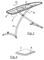
- the ironing board shown in Figure 1 has a foldable base 1, which a Ironing board 2 carries, which is made of a composite material made of plastic.
- the Cut edges 3 of the ironing board 2 are at least partially open. This applies to both Multi-wall sheets as well as for honeycomb composite sheets. These cut edges 3 are with a Fabric tape 4 sewn.
- the seam 5 is on both sides and is expediently with a heated needle performed.
- FIG. 1 An alternative solution is shown in FIG.
- the ironing board 2 and its cutting edge 3 is covered with padding 6.
- This padding 6 is in the range of Cutting edge 3 is encompassed by a fabric tape 8 and is en block over the seam 9 with the Ironing board 2 connected.
- the upholstery 6 is on top of one Printing method with a vapor-tight layer 10 (because of the better Understanding shown separately in the drawing).
- At 11 is the ironing board cover designated.
Landscapes
- Engineering & Computer Science (AREA)
- Textile Engineering (AREA)
- Irons (AREA)
Description
- Figur 1
- einen Bügeltisch mit einer Bügeltischplatte in einer perspektivischen Ansicht,
- Figur 2
- einen Schnitt gemäß der Linie II/II in Figur 1 und
- Figur 3
- eine abgewandelte Ausführungsform in einer der Figur 2 entsprechenden Schnittdarstellung und
- Figur 4
- eine Eckansicht einer Bügeltischplatte im Ausschnitt
- 1
- Fußgestell
- 2
- Bügeltischplatte
- 3
- Schnittkanten
- 4
- Gewebeband
- 5
- Naht
- 6
- Polsterung
- 8
- Gewebeband
- 9
- Naht
- 10
- Schicht
- 11
- Bügeltischbezug
Claims (7)
- Bügeltischplatte (2) aus einem Verbundmaterial aus Kunststoff mit einem Verschluss der Schnittkanten, dadurch gekennzeichnet, dass das zum Verschluss genutzte Material um die Schnittkante (3) gelegt und mit dem Verbundmaterial vernäht ist.
- Bügeltischplatte (2) nach Anspruch 1, dadurch gekennzeichnet, dass das Material aus einem Gewebeband (4) besteht.
- Bügeltischplatte (2) nach Anspruch 2, dadurch gekennzeichnet, dass das Gewebeband (4) mit einer Schaumstoffunterlage versehen ist.
- Bügeltischplatte (2) nach Anspruch 1, dadurch gekennzeichnet, dass das zum Verschluss genutzte Material ein einen Bügeltischbezug (11) unterstützende Polsterung (6) ist, die nach unten um die Schnittkante (3) umgelegt und mit dem Verbundmaterial beidseitig vernäht ist.
- Bügeltischplatte (2) nach Anspruch 4, dadurch gekennzeichnet, dass im Bereich der Schnittkante (3) zusätzlich ein Gewebeband (8) mitvernäht ist.
- Bügeltischplatte (2) nach Anspruch 4 oder 5, dadurch gekennzeichnet, dass die Polsterung (6) gegen den Bügeltischbezug (11) mit einer dampfdichten Schicht (10) versehen ist.
- Bügeltischplatte (2) nach Anspruch 6, dadurch gekennzeichnet, dass die dampfdichte Schicht (10) durch ein Bedruckungsverfahren aufgebracht ist.
Applications Claiming Priority (2)
| Application Number | Priority Date | Filing Date | Title |
|---|---|---|---|
| DE10035771 | 2000-07-22 | ||
| DE2000135771 DE10035771B4 (de) | 2000-07-22 | 2000-07-22 | Bügeltischplatte |
Publications (3)
| Publication Number | Publication Date |
|---|---|
| EP1174540A2 EP1174540A2 (de) | 2002-01-23 |
| EP1174540A3 EP1174540A3 (de) | 2002-10-23 |
| EP1174540B1 true EP1174540B1 (de) | 2004-03-17 |
Family
ID=7649880
Family Applications (1)
| Application Number | Title | Priority Date | Filing Date |
|---|---|---|---|
| EP20010117512 Expired - Lifetime EP1174540B1 (de) | 2000-07-22 | 2001-07-20 | Bügeltischplatte |
Country Status (2)
| Country | Link |
|---|---|
| EP (1) | EP1174540B1 (de) |
| DE (1) | DE10035771B4 (de) |
Family Cites Families (5)
| Publication number | Priority date | Publication date | Assignee | Title |
|---|---|---|---|---|
| US1708667A (en) * | 1926-11-11 | 1929-04-09 | Mary C Esmarian | Ironing-board-cover holder |
| US2907127A (en) * | 1955-12-08 | 1959-10-06 | Englander Co Inc | Ironing board |
| US3324584A (en) * | 1962-10-29 | 1967-06-13 | Pall Corp | Ironing board cover |
| US4043062A (en) * | 1976-05-26 | 1977-08-23 | The Ironees Company | Ironing pad |
| EP1002895B1 (de) * | 1998-11-18 | 2006-12-20 | LEIFHEIT Aktiengesellschaft | Bügelauflage, Bügeltischplatte und Bügeltisch |
-
2000
- 2000-07-22 DE DE2000135771 patent/DE10035771B4/de not_active Expired - Fee Related
-
2001
- 2001-07-20 EP EP20010117512 patent/EP1174540B1/de not_active Expired - Lifetime
Also Published As
| Publication number | Publication date |
|---|---|
| DE10035771B4 (de) | 2009-12-24 |
| EP1174540A2 (de) | 2002-01-23 |
| EP1174540A3 (de) | 2002-10-23 |
| DE10035771A1 (de) | 2002-01-31 |
Similar Documents
| Publication | Publication Date | Title |
|---|---|---|
| DE69212979T2 (de) | Luftundurchlässige gewellte stoffbahn für luftkissen und verfahren zu ihrer herstellung | |
| DE69114629T2 (de) | Segel aus einteiligem dreidimensionalem mehrschichtigem Stoff mit ununterbrochenen lasttragenden Garnen. | |
| EP0758992B1 (de) | Sack aus polymer-, insbesondere polyolefingewebe und verfahren zu seiner herstellung | |
| DE19719159A1 (de) | Luftsack für eine Luftsackvorrichtung | |
| DE69408229T2 (de) | Eine Vorrichtung und ein Verfahren zum Einsäumen von Rändern einer gespannten Folie und eine Folie mit eingesäumten Rändern | |
| DE29920222U1 (de) | Airbag | |
| DE2625886A1 (de) | Aufblasbares ruhekissen | |
| DE4215662A1 (de) | Textiles Anti-Vandalismus Flächengebilde | |
| DE60002352T2 (de) | In segmente gebildetes segel und verfahren zu dessen herstellung | |
| EP1174540B1 (de) | Bügeltischplatte | |
| DE7416719U (de) | Sack | |
| EP0686478A1 (de) | Metallteil mit Kaschierung und Verfahren zur Herstellung eines solchen | |
| DE2345820A1 (de) | Kammerfilter fuer fluide und verfahren zu seiner herstellung | |
| DE2217796A1 (de) | Drucktuch fuer offset-druckmaschinen | |
| DE4420808A1 (de) | Siegelwerkzeug, insbesondere an einer Schlauchbeutel-Verpackungsmaschine | |
| DE3118380C2 (de) | Verfahren zur Herstellung von dauerfixierten Faltenmustern in Stoffzuschnitten | |
| DE2146870C2 (de) | Polsterpfeifenbezug für Fahrzeugsitze | |
| DE9001528U1 (de) | Doppellagige Halteplatte aus Pappe für den Staubfilterbeutel eines Staubsaugers | |
| DE102020114228A1 (de) | Verfahren und Vorrichtung zur Herstellung großflächiger Nähgüter | |
| DE20206888U1 (de) | Gassack für ein Fahrzeuginsassen-Rückhaltesystem | |
| DE1532854C3 (de) | Etui mit einem Verschlußglied aus zwei Bügeln | |
| DE69707958T2 (de) | Zuschnitt für eine Decke | |
| DE3029242C2 (de) | Vorrichtung zur Herstellung eines Kissens, insbesondere Sitzkissens | |
| DE3527895C2 (de) | ||
| DE2919285C2 (de) | Plattenpresse zum Pressen von Preßgutlaminaten, Preßgutmatten u. dgl. |
Legal Events
| Date | Code | Title | Description |
|---|---|---|---|
| PUAI | Public reference made under article 153(3) epc to a published international application that has entered the european phase |
Free format text: ORIGINAL CODE: 0009012 |
|
| AK | Designated contracting states |
Kind code of ref document: A2 Designated state(s): AT BE CH CY DE DK ES FI FR GB GR IE IT LI LU MC NL PT SE TR |
|
| AX | Request for extension of the european patent |
Free format text: AL;LT;LV;MK;RO;SI |
|
| PUAL | Search report despatched |
Free format text: ORIGINAL CODE: 0009013 |
|
| RIC1 | Information provided on ipc code assigned before grant |
Free format text: 7D 06F 81/10 A, 7D 06F 83/00 B |
|
| AK | Designated contracting states |
Kind code of ref document: A3 Designated state(s): AT BE CH CY DE DK ES FI FR GB GR IE IT LI LU MC NL PT SE TR |
|
| AX | Request for extension of the european patent |
Free format text: AL;LT;LV;MK;RO;SI |
|
| 17P | Request for examination filed |
Effective date: 20021113 |
|
| AKX | Designation fees paid |
Designated state(s): BE FR GB IT NL |
|
| REG | Reference to a national code |
Ref country code: DE Ref legal event code: 8566 |
|
| GRAP | Despatch of communication of intention to grant a patent |
Free format text: ORIGINAL CODE: EPIDOSNIGR1 |
|
| GRAS | Grant fee paid |
Free format text: ORIGINAL CODE: EPIDOSNIGR3 |
|
| GRAA | (expected) grant |
Free format text: ORIGINAL CODE: 0009210 |
|
| AK | Designated contracting states |
Kind code of ref document: B1 Designated state(s): BE FR GB IT NL |
|
| REG | Reference to a national code |
Ref country code: GB Ref legal event code: FG4D Free format text: NOT ENGLISH |
|
| GBT | Gb: translation of ep patent filed (gb section 77(6)(a)/1977) |
Effective date: 20040317 |
|
| REG | Reference to a national code |
Ref country code: IE Ref legal event code: FG4D Free format text: GERMAN |
|
| PG25 | Lapsed in a contracting state [announced via postgrant information from national office to epo] |
Ref country code: BE Free format text: LAPSE BECAUSE OF NON-PAYMENT OF DUE FEES Effective date: 20040731 |
|
| REG | Reference to a national code |
Ref country code: IE Ref legal event code: FD4D |
|
| ET | Fr: translation filed | ||
| PLBE | No opposition filed within time limit |
Free format text: ORIGINAL CODE: 0009261 |
|
| STAA | Information on the status of an ep patent application or granted ep patent |
Free format text: STATUS: NO OPPOSITION FILED WITHIN TIME LIMIT |
|
| BERE | Be: lapsed |
Owner name: *LEIFHEIT A.G. Effective date: 20040731 |
|
| 26N | No opposition filed |
Effective date: 20041220 |
|
| BERE | Be: lapsed |
Owner name: *LEIFHEIT A.G. Effective date: 20040731 |
|
| REG | Reference to a national code |
Ref country code: FR Ref legal event code: PLFP Year of fee payment: 15 |
|
| PGFP | Annual fee paid to national office [announced via postgrant information from national office to epo] |
Ref country code: GB Payment date: 20150624 Year of fee payment: 15 |
|
| PGFP | Annual fee paid to national office [announced via postgrant information from national office to epo] |
Ref country code: FR Payment date: 20150624 Year of fee payment: 15 |
|
| PGFP | Annual fee paid to national office [announced via postgrant information from national office to epo] |
Ref country code: NL Payment date: 20150708 Year of fee payment: 15 |
|
| PGFP | Annual fee paid to national office [announced via postgrant information from national office to epo] |
Ref country code: IT Payment date: 20150716 Year of fee payment: 15 |
|
| REG | Reference to a national code |
Ref country code: NL Ref legal event code: MM Effective date: 20160801 |
|
| GBPC | Gb: european patent ceased through non-payment of renewal fee |
Effective date: 20160720 |
|
| PG25 | Lapsed in a contracting state [announced via postgrant information from national office to epo] |
Ref country code: NL Free format text: LAPSE BECAUSE OF NON-PAYMENT OF DUE FEES Effective date: 20160801 Ref country code: FR Free format text: LAPSE BECAUSE OF NON-PAYMENT OF DUE FEES Effective date: 20160801 |
|
| REG | Reference to a national code |
Ref country code: FR Ref legal event code: ST Effective date: 20170331 |
|
| PG25 | Lapsed in a contracting state [announced via postgrant information from national office to epo] |
Ref country code: GB Free format text: LAPSE BECAUSE OF NON-PAYMENT OF DUE FEES Effective date: 20160720 |
|
| PG25 | Lapsed in a contracting state [announced via postgrant information from national office to epo] |
Ref country code: IT Free format text: LAPSE BECAUSE OF NON-PAYMENT OF DUE FEES Effective date: 20160720 |