EP1174237B1 - Elektrisches Gerät mit einem Gehäuse aus verfestigtem polymerem Werkstoff - Google Patents
Elektrisches Gerät mit einem Gehäuse aus verfestigtem polymerem Werkstoff Download PDFInfo
- Publication number
- EP1174237B1 EP1174237B1 EP01114638A EP01114638A EP1174237B1 EP 1174237 B1 EP1174237 B1 EP 1174237B1 EP 01114638 A EP01114638 A EP 01114638A EP 01114638 A EP01114638 A EP 01114638A EP 1174237 B1 EP1174237 B1 EP 1174237B1
- Authority
- EP
- European Patent Office
- Prior art keywords
- wall
- housing
- flexible conductor
- conductor track
- electrical
- Prior art date
- Legal status (The legal status is an assumption and is not a legal conclusion. Google has not performed a legal analysis and makes no representation as to the accuracy of the status listed.)
- Expired - Lifetime
Links
Images



Classifications
-
- H—ELECTRICITY
- H05—ELECTRIC TECHNIQUES NOT OTHERWISE PROVIDED FOR
- H05K—PRINTED CIRCUITS; CASINGS OR CONSTRUCTIONAL DETAILS OF ELECTRIC APPARATUS; MANUFACTURE OF ASSEMBLAGES OF ELECTRICAL COMPONENTS
- H05K5/00—Casings, cabinets or drawers for electric apparatus
- H05K5/0026—Casings, cabinets or drawers for electric apparatus provided with connectors and printed circuit boards [PCB], e.g. automotive electronic control units
- H05K5/0069—Casings, cabinets or drawers for electric apparatus provided with connectors and printed circuit boards [PCB], e.g. automotive electronic control units having connector relating features for connecting the connector pins with the PCB or for mounting the connector body with the housing
-
- B—PERFORMING OPERATIONS; TRANSPORTING
- B29—WORKING OF PLASTICS; WORKING OF SUBSTANCES IN A PLASTIC STATE IN GENERAL
- B29C—SHAPING OR JOINING OF PLASTICS; SHAPING OF MATERIAL IN A PLASTIC STATE, NOT OTHERWISE PROVIDED FOR; AFTER-TREATMENT OF THE SHAPED PRODUCTS, e.g. REPAIRING
- B29C45/00—Injection moulding, i.e. forcing the required volume of moulding material through a nozzle into a closed mould; Apparatus therefor
- B29C45/14—Injection moulding, i.e. forcing the required volume of moulding material through a nozzle into a closed mould; Apparatus therefor incorporating preformed parts or layers, e.g. injection moulding around inserts or for coating articles
- B29C45/14639—Injection moulding, i.e. forcing the required volume of moulding material through a nozzle into a closed mould; Apparatus therefor incorporating preformed parts or layers, e.g. injection moulding around inserts or for coating articles for obtaining an insulating effect, e.g. for electrical components
-
- H—ELECTRICITY
- H05—ELECTRIC TECHNIQUES NOT OTHERWISE PROVIDED FOR
- H05K—PRINTED CIRCUITS; CASINGS OR CONSTRUCTIONAL DETAILS OF ELECTRIC APPARATUS; MANUFACTURE OF ASSEMBLAGES OF ELECTRICAL COMPONENTS
- H05K1/00—Printed circuits
- H05K1/18—Printed circuits structurally associated with non-printed electric components
- H05K1/189—Printed circuits structurally associated with non-printed electric components characterised by the use of flexible or folded printed circuits
-
- H—ELECTRICITY
- H05—ELECTRIC TECHNIQUES NOT OTHERWISE PROVIDED FOR
- H05K—PRINTED CIRCUITS; CASINGS OR CONSTRUCTIONAL DETAILS OF ELECTRIC APPARATUS; MANUFACTURE OF ASSEMBLAGES OF ELECTRICAL COMPONENTS
- H05K5/00—Casings, cabinets or drawers for electric apparatus
- H05K5/02—Details
- H05K5/0247—Electrical details of casings, e.g. terminals, passages for cables or wiring
-
- B—PERFORMING OPERATIONS; TRANSPORTING
- B29—WORKING OF PLASTICS; WORKING OF SUBSTANCES IN A PLASTIC STATE IN GENERAL
- B29L—INDEXING SCHEME ASSOCIATED WITH SUBCLASS B29C, RELATING TO PARTICULAR ARTICLES
- B29L2031/00—Other particular articles
- B29L2031/34—Electrical apparatus, e.g. sparking plugs or parts thereof
- B29L2031/3481—Housings or casings incorporating or embedding electric or electronic elements
Definitions
- the invention relates to an electrical device comprising a housing with a Wall made of solidified polymeric material and at least one within the Housing arranged, electrical component by at least one electrical line with at least one outside or inside the Housing arranged electrical component is connected, wherein the line designed as a flexible conductor and at least partially into the wall of the Housing is embedded.
- the housing a plastic molding used for protection or as a carrier for electrical Function units is used.
- Electrical apparatus in particular those in Vehicles used must be difficult Can withstand environmental conditions, such as dirt and Dust, high temperature fluctuations, humidity, in particular Moisture condensation and as a result, corrosion.
- flexible strip conductors from mechanical damage or before To protect oxidation by providing it with a thermoplastic Back-injected material.
- a printed circuit board in which a flexible carrier is back-injected with a thermoplastic material is known from document EP 0 485 838.
- a plastic molded part with a protected conductor track is known from the document DE OS 198 12 880. The track is embedded between a plastic film and a cover sheet. The plastic molding can be used for the electromagnetic shielding of electrical equipment.
- DE 197 42 178 C1 discloses a process in which for the production a dense, electrical cable feedthrough into a housing wall a flexible film having a conductor track, each at the to be sprayed Outside of the housing and the inside of the housing to be sprayed between two Halves of an injection mold is clamped and injected.
- the object of the invention is an electrical device of the type mentioned with a plastic housing to indicate that electrical components outside or inside the housing, especially solid and movable housing parts, electrically connected in a technically simple manner and manufacturing costs of the device can be reduced.
- the line is flexible and in the Shaping and solidification of the housing at least partially in the wall the housing is embedded and that the flexible interconnect at least has a partial area which is flush with the surface embedded in the wall and at least one free contact field is provided.
- the flexible interconnect at least has a partial area which is flush with the surface embedded in the wall and at least one free contact field is provided.
- Running in the wall of the housing Cables are better against mechanical damage and moisture protected as exposed cables. This increases the reliability of the Device.
- the housing of these devices exists usually made of housing parts with complex three-dimensional structure.
- the electrical components can be outside or inside the housing arranged to be electrical switches or connectors. Connectors can be cast prefabricated. This shortens the assembly time. As the wiring is done in the wall, there is room saved up. The elimination of boards for routing reduced also the weight of the device. Also electronic components that the Temperature of the plastic melt can withstand, can velvet Connection technology can be accommodated in the housing wall.
- the embedding of the conductor track as from the state of Technique known during injection molding of the housing in one step he follows.
- the envelope of the ladder is thereby cost-effectively in one piece produced. This allows the electrical device particularly inexpensive getting produced.
- the flexible conductor is inserted in the cavity of a Injection molding tool placed, the tool closed and the envelope made with the plastic melt in one piece. After hardening is the flexible trace by the solidification of the plastic melt from polymer material practically "buried". From the flexible line was a solidified in the plastic of the housing line.
- the flexible conductor at least two side by side includes lying conductor. This allows the plastic in the housing wall lying line several functional units or electrical components connect. It can be inexpensively simple housing components manufactured which include return conductors to limit switches or actuators.
- the flexible trace with spacer elements is provided, which set a distance from a surface of the wall. This achieves a defined position of the conductor track in the housing. It will avoided that the electrical wire during injection molding to the unprotected Surface of the housing comes. It is advantageous if the flexible Track is provided with bends. These bends can be at the production of the flexible conductor by punching the carrier film with low cost.
- the conductor additionally comprises at least one contact element carries, which is embedded in the wall. This allows prefabricated Lines at the ends of connectors are provided as so-called Process inserts. Connectors and electrical wiring are therefore part of Housing of the electrical device.
- the flexible conductor at least in two different Partial areas of the wall is embedded flush with the surface. It can thereby several electrical components on the surface of the housing electrically get connected.
- the electrical line is continuous in one Distance from the surface is embedded in the wall and essentially in the middle of the wall runs.
- the electrical line is characterized mechanical effects and best protected from moisture.
- the electrical line a Reinforcement forms in the wall of the housing. You can easily This can be achieved by the carrier film and / or the conductor structure correspondingly thick and formed with a suitable shape. To this Way, the dimensional stability of the plastic housing simply reinforced become. It is preferred when the wall of the electrical appliance off thermoplastic material. Leave thermoplastic materials process itself particularly well by injection molding. Particularly suitable is a Plastic from the series polyamide, polyester, polyurethanes, polyacetals, Polystyrenes, polyimides, polyphenylene oxide, polycarbonate, polyphenyl sulfide, Polypropylene and copolymers thereof or mixtures of these Polymers.
- a flexible conductor can be injection molded in one step a polymeric material can be integrated in a housing section. From Advantage here is when the flexible conductor provided with spacers is. Through these spacer elements, it is possible in injection molding a to maintain a defined distance from the cavity surface. The course of the flexible trace in the housing can thereby be in the middle of the wall be specified, so that the conductor track against mechanical effects and is well protected from moisture.
- FIGS. 1, 2 and 3 are examples showing the To facilitate understanding of the invention.
- Figure 1 is simplified schematically illustrated how an electrical line. 4 Components 5 outside and inside an electrical device 1 combines. Along a section is the electrical line 4 in the wall. 2 led of the housing. The distance to the surface 3, both to the interior 6 as well as the surface of the outer space, is formed by spacer elements. 9 specified.
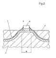
- Figure 2 shows a section of a housing wall 2 with an electrical Line 7, which in a partial area 10 flush with the wall is embedded. In this portion 10 of the surface 3 is in the interior. 6 an electronic component 12 is shown, which by soldering with the Track is connected.
- Figure 3 shows a sectional view through a housing wall 2 with an approximately in the middle of the housing wall extending flexible conductor 7, at the End of a contact element 8 is arranged.
- the contact element 8 closes flush with the surface 3 from.
- a flexible conductor 7 is shown, which in a partial area 10th a contact pad 11 which is flush with the surface 3 of Housing wall 2 closes. In this way it is possible along the 5 portion 10 by means of a sliding contact 13 a movable electrical Establish connection to a component, not shown.
Landscapes
- Engineering & Computer Science (AREA)
- Microelectronics & Electronic Packaging (AREA)
- Manufacturing & Machinery (AREA)
- Mechanical Engineering (AREA)
- Injection Moulding Of Plastics Or The Like (AREA)
- Casings For Electric Apparatus (AREA)
- Insertion, Bundling And Securing Of Wires For Electric Apparatuses (AREA)
- Mounting Of Printed Circuit Boards And The Like (AREA)
- Connection Or Junction Boxes (AREA)
Description
Ein Kunststoffformteil mit geschützter Leiterbahn ist aus der Schrift DE OS 198 12 880 bekannt. Die Leiterbahn ist zwischen einer Kunststofffolie und einer Deckfolie eingebettet. Das Kunststoffformteil kann zur elektromagnetischen Abschirmung von elektrischen Geräten verwendet werden.
- Figur 1
- eine vereinfachte schematische Darstellung eines Teilbereichs eines elektrischen Gerätes im Querschnitt,
- Figur 2
- eine vergrößerte schematische Darstellung eines Ausschnitts aus der Gehäusewand mit einer flexiblen Leiterbahn und einem elektronischen Bauteil im Querschnitt,
- Figur 3
- einen Schnitt durch eine Gehäusewand mit einer flexiblen Leiterbahn und einem Kontaktelement,
- Figur 4
- einen Ausschnitt aus der Gehäusewand mit einer flexiblen Leiterbahn und einem Kontaktfeld in schematischer Darstellung.
Claims (11)
- Elektrisches Gerät, umfassend ein Gehäuse mit einer Wand (2) aus verfestigtem polymerem Werksstoff und zumindest ein innerhalb des Gehäuses angeordnetes, elektrisches Bauteil (5), das durch zumindest eine elektrische Leitung (4) mit zumindest einem außerhalb oder innerhalb des Gehäuses angeordneten elektrischen Bauteil verbunden ist, wobei die Leitung (4) flexible Leiterbahn ausgebildet und zumindest teilweise in die Wand (2) des Gehäuses eingebettet wird, dadurch gekennzeichnet, dass die flexible Leiterbahn (7) zumindest einen Teilbereich (10) aufweist, der oberflächenbündig in die Wand (2) eingebettet ist und zumindest ein freies Kontaktfeld (11) ausbildet.
- Gerät nach Anspruch 1, dadurch gekennzeichnet, dass die Einbettung eines Längenabschnittes der flexiblen Leiterbahn in einem Arbeitsschritt durch Spritzgießen des polymeren Werkstoffes gebildet wird.
- Gerät nach Anspruch 2, dadurch gekennzeichnet, dass die flexible Leiterbahn (7) zumindest zwei nebeneinander liegende Leiter umfasst.
- Gerät nach Anspruch 2, dadurch gekennzeichnet, dass die flexible Leiterbahn (7) mit Abstandselementen versehen ist, welche einen Abstand von einer Oberfläche (3) der Wand festlegen.
- Gerät nach Anspruch 4, dadurch gekennzeichnet, dass die flexible Leiterbahn (7) mit Abbiegungen (9) versehen ist.
- Gerät nach Anspruch 2, dadurch gekennzeichnet, dass die flexible Leiterbahn (7) zumindest ein Kontaktelement (8) trägt, welches in die Wand (2) eingebettet ist.
- Gerät nach Anspruch 2, dadurch gekennzeichnet, dass die flexible Leiterbahn (7) zumindest in zwei verschiedenen Teilbereichen der Wand (2) oberflächenbündig eingebettet ist.
- Gerät nach Anspruch 2, dadurch gekennzeichnet, dass die flexible Leiterbahn durchgehend in einem Abstand zur Oberfläche in die Wand eingebettet ist und im wesentlichen in der Mitte der Wand verläuft.
- Gerät nach Anspruch 1, dadurch gekennzeichnet, dass die Leitung (4) eine Armierung in der Wand (2) des Gehäuses bildet.
- Gerät nach Anspruch 1, dadurch gekennzeichnet, dass die Wand (2) aus thermoplastischem Kunststoff besteht.
- Gerät nach Anspruch 10, dadurch gekennzeichnet, dass die Erweichungstemperatur der flexiblen Leiterbahn größer ist als die Erweichungstemperatur des thermoplastischen Kunststoffes.
Applications Claiming Priority (2)
| Application Number | Priority Date | Filing Date | Title |
|---|---|---|---|
| DE10032849A DE10032849C2 (de) | 2000-07-06 | 2000-07-06 | Elektrisches Gerät mit einem Gehäuse aus verfestigtem polymeren Werkstoff |
| DE10032849 | 2000-07-06 |
Publications (2)
| Publication Number | Publication Date |
|---|---|
| EP1174237A1 EP1174237A1 (de) | 2002-01-23 |
| EP1174237B1 true EP1174237B1 (de) | 2005-11-09 |
Family
ID=7647993
Family Applications (1)
| Application Number | Title | Priority Date | Filing Date |
|---|---|---|---|
| EP01114638A Expired - Lifetime EP1174237B1 (de) | 2000-07-06 | 2001-06-19 | Elektrisches Gerät mit einem Gehäuse aus verfestigtem polymerem Werkstoff |
Country Status (4)
| Country | Link |
|---|---|
| US (1) | US6573447B2 (de) |
| EP (1) | EP1174237B1 (de) |
| JP (1) | JP2002112433A (de) |
| DE (2) | DE10032849C2 (de) |
Families Citing this family (9)
| Publication number | Priority date | Publication date | Assignee | Title |
|---|---|---|---|---|
| DE10139577C1 (de) * | 2001-08-10 | 2002-12-19 | Freudenberg Carl Kg | Elektrisches Gerät mit einer Wandung aus Kunststoff, umfassend zumindest einen flexiblen Leiter, sowie ein Verfahren zur Herstellung eines solchen elektrischen Geräts |
| DE10239395A1 (de) * | 2002-08-28 | 2004-03-11 | Zf Friedrichshafen Ag | Vorrichtung zur Verbindung eines elektrischen oder elektronischen Bauteils mit wenigstens einem elektrischen Leiter |
| DE10330789A1 (de) * | 2003-07-07 | 2005-02-03 | Carl Freudenberg Kg | Gehäuse für elektrische oder elektronische Vorrichtungen |
| DE102004033559A1 (de) * | 2004-07-09 | 2006-02-09 | Zf Friedrichshafen Ag | Abdichtung eines Steuergerätes |
| DE102005022536A1 (de) | 2005-05-17 | 2006-11-23 | Siemens Ag | Steuereinheit mit einer flexiblen Leiterplatte |
| WO2008099009A1 (de) * | 2007-02-15 | 2008-08-21 | Basf Se | Verfahren zur herstellung eines bauteils sowie bauteil |
| DE102008042674A1 (de) * | 2008-10-08 | 2010-05-12 | BSH Bosch und Siemens Hausgeräte GmbH | Hausgerätvorrichtung |
| DE102011007278B4 (de) * | 2011-04-13 | 2025-10-16 | Zf Friedrichshafen Ag | Steuergerät und Getriebe für ein Fahrzeug |
| DE102012017908A1 (de) * | 2012-09-11 | 2014-03-13 | Gm Tec Industries Holding Gmbh | Gehäusedeckel eines Getriebegehäuses |
Family Cites Families (15)
| Publication number | Priority date | Publication date | Assignee | Title |
|---|---|---|---|---|
| US3839596A (en) * | 1973-05-07 | 1974-10-01 | Amp Inc | Flexible airtight stranded wire |
| DE4036592A1 (de) * | 1990-11-16 | 1992-05-21 | Bayer Ag | Spritzgegossene leiterplatten durch hinterspritzen von flexiblen schaltungen mit thermoplastischen materialien |
| US5464428A (en) * | 1994-03-08 | 1995-11-07 | Physio-Control Corporation | Environmentally protected medical electronic instrument |
| US5840402A (en) * | 1994-06-24 | 1998-11-24 | Sheldahl, Inc. | Metallized laminate material having ordered distribution of conductive through holes |
| DE9420980U1 (de) * | 1994-11-25 | 1995-02-23 | AMI DODUCO GmbH, 75181 Pforzheim | Zum Aufnehmen von elektronischen und/oder mikromechanischen Bauteilen bestimmtes Gehäuse aus einem Hartkunststoff, ins welches Leiterbahnen hineinführen |
| DE19606187A1 (de) * | 1996-02-20 | 1997-08-21 | Bosch Gmbh Robert | Gehäuse zur Unterbringung eines elektrischen Gerätes mit vom Gehäuseäußeren zugänglichen elektrischen Kontakten |
| CN1101748C (zh) * | 1997-05-21 | 2003-02-19 | 旭化成株式会社 | 热塑料树脂的注塑方法 |
| DE19733237C1 (de) * | 1997-08-01 | 1999-05-20 | Barlian Reinhold | Elektrisches Gerät |
| DE19804607C2 (de) * | 1998-02-06 | 2000-02-10 | Bosch Gmbh Robert | Anordnung zum elektrischen Anschluß zumindest eines Sensors |
| DE19812880A1 (de) * | 1998-03-24 | 1999-09-30 | Bayer Ag | Formteil und flexible Folie mit geschützter Leiterbahn und Verfahren zu ihrer Herstellung |
| DE19817198C2 (de) * | 1998-04-17 | 2002-10-31 | Siemens Ag | Elektrische Verbindungsanordnung |
| JP2000031606A (ja) * | 1998-07-10 | 2000-01-28 | Matsushita Electric Ind Co Ltd | モールド配線板とその製造方法 |
| US6110576A (en) * | 1998-10-16 | 2000-08-29 | Lucent Technologies Inc. | Article comprising molded circuit |
| US6233155B1 (en) * | 1999-06-03 | 2001-05-15 | Telefonaktiebolaget Lm Ericsson (Publ) | Encapsulation of printed circuit boards |
| DE29910305U1 (de) * | 1999-06-12 | 2000-11-16 | Robert Bosch Gmbh, 70469 Stuttgart | Elektrisches Gerät |
-
2000
- 2000-07-06 DE DE10032849A patent/DE10032849C2/de not_active Expired - Fee Related
-
2001
- 2001-06-19 EP EP01114638A patent/EP1174237B1/de not_active Expired - Lifetime
- 2001-06-19 DE DE50107957T patent/DE50107957D1/de not_active Expired - Lifetime
- 2001-07-03 JP JP2001201870A patent/JP2002112433A/ja active Pending
- 2001-07-06 US US09/900,638 patent/US6573447B2/en not_active Expired - Lifetime
Also Published As
| Publication number | Publication date |
|---|---|
| DE10032849C2 (de) | 2002-06-20 |
| US20020031940A1 (en) | 2002-03-14 |
| DE50107957D1 (de) | 2005-12-15 |
| EP1174237A1 (de) | 2002-01-23 |
| DE10032849A1 (de) | 2002-01-24 |
| US6573447B2 (en) | 2003-06-03 |
| JP2002112433A (ja) | 2002-04-12 |
Similar Documents
| Publication | Publication Date | Title |
|---|---|---|
| DE69919216T2 (de) | Fernsteuerung mit integral gegossenem sender | |
| DE102012221002B4 (de) | Abwinkelbare und/oder abgewinkelte Leiterplattenstruktur mit zumindest zwei Leiterplattenabschnitten und Verfahren zu deren Herstellung | |
| EP1230107B1 (de) | Steuergerät für ein kraftfahrzeug | |
| DE112017000235T5 (de) | Formkörper mit integriertem elektrodenmuster und verfahren zur herstellung desselben | |
| DE10032849C2 (de) | Elektrisches Gerät mit einem Gehäuse aus verfestigtem polymeren Werkstoff | |
| DE10051884A1 (de) | Verfahren zur Herstellung von Leiterfolie-Trägergehäuse-Einheiten | |
| DE60123742T2 (de) | Elektrisches Bauelement mit Leiterzügen | |
| WO2014005571A2 (de) | Elektrokomponententräger für ein kraftfahrzeug nebst herstellung | |
| EP1842404B1 (de) | Verfahren zur herstellung einer abwinkelbaren leiterplattenstruktur aus zumindest zwei leiterplattenabschnitten | |
| DE19719436C2 (de) | Spritzgußgehäuse | |
| EP1734621A2 (de) | Anordnung und Verfahren zum elektrischen Anschluss einer elektronischen Schaltung in einem Gehäuse | |
| DE19916949B4 (de) | Gehäuse, insbesondere Schloßgehäuse für einen Kraftfahrzeugtürverschluß, Getriebegehäuse oder dergleichen Leitungsträger | |
| WO2013178212A2 (de) | Kraftfahrzeug-komponententräger und verfahren zu seiner herstellung | |
| EP1791218A2 (de) | Elektrischer Verbinder | |
| DE102011002741A1 (de) | Sensormodul und Verfahren zum Herstellen eines Sensormoduls | |
| EP0982805B1 (de) | Elektrisches Verbindungselement | |
| DE4235056C2 (de) | Kontaktspirale | |
| DE4111975A1 (de) | Reedkontakttraeger und verfahren zu seiner herstellung | |
| DE10063367A1 (de) | Elektrisches Kraftfahrzeugschloß-Modul und Verfahren zu seiner Herstellung | |
| DE102005042248B3 (de) | Formbauteil für ein Kraftfahrzeug und Verfahren zu dessen Herstellung | |
| DE3048008C2 (de) | ||
| EP1351560A2 (de) | Verfahren zur Herstellung eines elektronischen Geräts und elektronisches Gerät | |
| EP1501341A2 (de) | Anordnung zum Führen von elektrischen Leiterbahnen | |
| DE102012211760A1 (de) | Verfahren zum Herstellen eines Elektrokomponententrägers | |
| DE102012208077A1 (de) | Mikroschalter mit Mehrfachpositionserkennung für ein Schließsystem für ein Fahrzeug sowie ein Verfahren zur Herstellung eines Mikroschalters mit Mehrfachpositionserkennung |
Legal Events
| Date | Code | Title | Description |
|---|---|---|---|
| PUAI | Public reference made under article 153(3) epc to a published international application that has entered the european phase |
Free format text: ORIGINAL CODE: 0009012 |
|
| AK | Designated contracting states |
Kind code of ref document: A1 Designated state(s): AT BE CH CY DE DK ES FI FR GB GR IE IT LI LU MC NL PT SE TR Kind code of ref document: A1 Designated state(s): DE FR GB IT |
|
| AX | Request for extension of the european patent |
Free format text: AL;LT;LV;MK;RO;SI |
|
| 17P | Request for examination filed |
Effective date: 20020215 |
|
| AKX | Designation fees paid |
Free format text: DE FR GB IT |
|
| 17Q | First examination report despatched |
Effective date: 20040317 |
|
| GRAP | Despatch of communication of intention to grant a patent |
Free format text: ORIGINAL CODE: EPIDOSNIGR1 |
|
| GRAS | Grant fee paid |
Free format text: ORIGINAL CODE: EPIDOSNIGR3 |
|
| GRAA | (expected) grant |
Free format text: ORIGINAL CODE: 0009210 |
|
| AK | Designated contracting states |
Kind code of ref document: B1 Designated state(s): DE FR GB IT |
|
| REG | Reference to a national code |
Ref country code: GB Ref legal event code: FG4D Free format text: NOT ENGLISH |
|
| REF | Corresponds to: |
Ref document number: 50107957 Country of ref document: DE Date of ref document: 20051215 Kind code of ref document: P |
|
| GBT | Gb: translation of ep patent filed (gb section 77(6)(a)/1977) |
Effective date: 20060108 |
|
| ET | Fr: translation filed | ||
| PLBE | No opposition filed within time limit |
Free format text: ORIGINAL CODE: 0009261 |
|
| STAA | Information on the status of an ep patent application or granted ep patent |
Free format text: STATUS: NO OPPOSITION FILED WITHIN TIME LIMIT |
|
| 26N | No opposition filed |
Effective date: 20060810 |
|
| REG | Reference to a national code |
Ref country code: GB Ref legal event code: 732E Free format text: REGISTERED BETWEEN 20100304 AND 20100310 |
|
| REG | Reference to a national code |
Ref country code: FR Ref legal event code: TP |
|
| REG | Reference to a national code |
Ref country code: FR Ref legal event code: PLFP Year of fee payment: 16 |
|
| REG | Reference to a national code |
Ref country code: FR Ref legal event code: PLFP Year of fee payment: 17 |
|
| REG | Reference to a national code |
Ref country code: FR Ref legal event code: PLFP Year of fee payment: 18 |
|
| PGFP | Annual fee paid to national office [announced via postgrant information from national office to epo] |
Ref country code: FR Payment date: 20200526 Year of fee payment: 20 Ref country code: DE Payment date: 20200528 Year of fee payment: 20 |
|
| PGFP | Annual fee paid to national office [announced via postgrant information from national office to epo] |
Ref country code: GB Payment date: 20200610 Year of fee payment: 20 Ref country code: IT Payment date: 20200527 Year of fee payment: 20 |
|
| REG | Reference to a national code |
Ref country code: DE Ref legal event code: R071 Ref document number: 50107957 Country of ref document: DE |
|
| REG | Reference to a national code |
Ref country code: GB Ref legal event code: PE20 Expiry date: 20210618 |
|
| PG25 | Lapsed in a contracting state [announced via postgrant information from national office to epo] |
Ref country code: GB Free format text: LAPSE BECAUSE OF EXPIRATION OF PROTECTION Effective date: 20210618 |