EP1173103B1 - Modification of airways by application of energy - Google Patents
Modification of airways by application of energy Download PDFInfo
- Publication number
- EP1173103B1 EP1173103B1 EP00930131A EP00930131A EP1173103B1 EP 1173103 B1 EP1173103 B1 EP 1173103B1 EP 00930131 A EP00930131 A EP 00930131A EP 00930131 A EP00930131 A EP 00930131A EP 1173103 B1 EP1173103 B1 EP 1173103B1
- Authority
- EP
- European Patent Office
- Prior art keywords
- airway
- energy transfer
- legs
- energy
- treatment
- Prior art date
- Legal status (The legal status is an assumption and is not a legal conclusion. Google has not performed a legal analysis and makes no representation as to the accuracy of the status listed.)
- Expired - Lifetime
Links
Images


Classifications
-
- A—HUMAN NECESSITIES
- A61—MEDICAL OR VETERINARY SCIENCE; HYGIENE
- A61B—DIAGNOSIS; SURGERY; IDENTIFICATION
- A61B18/00—Surgical instruments, devices or methods for transferring non-mechanical forms of energy to or from the body
-
- A—HUMAN NECESSITIES
- A61—MEDICAL OR VETERINARY SCIENCE; HYGIENE
- A61B—DIAGNOSIS; SURGERY; IDENTIFICATION
- A61B18/00—Surgical instruments, devices or methods for transferring non-mechanical forms of energy to or from the body
- A61B18/04—Surgical instruments, devices or methods for transferring non-mechanical forms of energy to or from the body by heating
- A61B18/12—Surgical instruments, devices or methods for transferring non-mechanical forms of energy to or from the body by heating by passing a current through the tissue to be heated, e.g. high-frequency current
-
- A—HUMAN NECESSITIES
- A61—MEDICAL OR VETERINARY SCIENCE; HYGIENE
- A61B—DIAGNOSIS; SURGERY; IDENTIFICATION
- A61B18/00—Surgical instruments, devices or methods for transferring non-mechanical forms of energy to or from the body
- A61B18/04—Surgical instruments, devices or methods for transferring non-mechanical forms of energy to or from the body by heating
- A61B18/08—Surgical instruments, devices or methods for transferring non-mechanical forms of energy to or from the body by heating by means of electrically-heated probes
-
- A—HUMAN NECESSITIES
- A61—MEDICAL OR VETERINARY SCIENCE; HYGIENE
- A61B—DIAGNOSIS; SURGERY; IDENTIFICATION
- A61B18/00—Surgical instruments, devices or methods for transferring non-mechanical forms of energy to or from the body
- A61B18/04—Surgical instruments, devices or methods for transferring non-mechanical forms of energy to or from the body by heating
- A61B18/12—Surgical instruments, devices or methods for transferring non-mechanical forms of energy to or from the body by heating by passing a current through the tissue to be heated, e.g. high-frequency current
- A61B18/14—Probes or electrodes therefor
- A61B18/1485—Probes or electrodes therefor having a short rigid shaft for accessing the inner body through natural openings
-
- A—HUMAN NECESSITIES
- A61—MEDICAL OR VETERINARY SCIENCE; HYGIENE
- A61B—DIAGNOSIS; SURGERY; IDENTIFICATION
- A61B18/00—Surgical instruments, devices or methods for transferring non-mechanical forms of energy to or from the body
- A61B18/04—Surgical instruments, devices or methods for transferring non-mechanical forms of energy to or from the body by heating
- A61B18/12—Surgical instruments, devices or methods for transferring non-mechanical forms of energy to or from the body by heating by passing a current through the tissue to be heated, e.g. high-frequency current
- A61B18/14—Probes or electrodes therefor
- A61B18/1492—Probes or electrodes therefor having a flexible, catheter-like structure, e.g. for heart ablation
-
- A—HUMAN NECESSITIES
- A61—MEDICAL OR VETERINARY SCIENCE; HYGIENE
- A61M—DEVICES FOR INTRODUCING MEDIA INTO, OR ONTO, THE BODY; DEVICES FOR TRANSDUCING BODY MEDIA OR FOR TAKING MEDIA FROM THE BODY; DEVICES FOR PRODUCING OR ENDING SLEEP OR STUPOR
- A61M25/00—Catheters; Hollow probes
- A61M25/0043—Catheters; Hollow probes characterised by structural features
-
- A—HUMAN NECESSITIES
- A61—MEDICAL OR VETERINARY SCIENCE; HYGIENE
- A61M—DEVICES FOR INTRODUCING MEDIA INTO, OR ONTO, THE BODY; DEVICES FOR TRANSDUCING BODY MEDIA OR FOR TAKING MEDIA FROM THE BODY; DEVICES FOR PRODUCING OR ENDING SLEEP OR STUPOR
- A61M29/00—Dilators with or without means for introducing media, e.g. remedies
-
- A—HUMAN NECESSITIES
- A61—MEDICAL OR VETERINARY SCIENCE; HYGIENE
- A61N—ELECTROTHERAPY; MAGNETOTHERAPY; RADIATION THERAPY; ULTRASOUND THERAPY
- A61N5/00—Radiation therapy
- A61N5/06—Radiation therapy using light
- A61N5/0601—Apparatus for use inside the body
-
- A—HUMAN NECESSITIES
- A61—MEDICAL OR VETERINARY SCIENCE; HYGIENE
- A61B—DIAGNOSIS; SURGERY; IDENTIFICATION
- A61B17/00—Surgical instruments, devices or methods, e.g. tourniquets
- A61B17/22—Implements for squeezing-off ulcers or the like on the inside of inner organs of the body; Implements for scraping-out cavities of body organs, e.g. bones; Calculus removers; Calculus smashing apparatus; Apparatus for removing obstructions in blood vessels, not otherwise provided for
- A61B17/22004—Implements for squeezing-off ulcers or the like on the inside of inner organs of the body; Implements for scraping-out cavities of body organs, e.g. bones; Calculus removers; Calculus smashing apparatus; Apparatus for removing obstructions in blood vessels, not otherwise provided for using mechanical vibrations, e.g. ultrasonic shock waves
-
- A—HUMAN NECESSITIES
- A61—MEDICAL OR VETERINARY SCIENCE; HYGIENE
- A61B—DIAGNOSIS; SURGERY; IDENTIFICATION
- A61B18/00—Surgical instruments, devices or methods for transferring non-mechanical forms of energy to or from the body
- A61B18/04—Surgical instruments, devices or methods for transferring non-mechanical forms of energy to or from the body by heating
- A61B18/12—Surgical instruments, devices or methods for transferring non-mechanical forms of energy to or from the body by heating by passing a current through the tissue to be heated, e.g. high-frequency current
- A61B18/14—Probes or electrodes therefor
-
- A—HUMAN NECESSITIES
- A61—MEDICAL OR VETERINARY SCIENCE; HYGIENE
- A61B—DIAGNOSIS; SURGERY; IDENTIFICATION
- A61B17/00—Surgical instruments, devices or methods, e.g. tourniquets
- A61B2017/00017—Electrical control of surgical instruments
- A61B2017/00115—Electrical control of surgical instruments with audible or visual output
-
- A—HUMAN NECESSITIES
- A61—MEDICAL OR VETERINARY SCIENCE; HYGIENE
- A61B—DIAGNOSIS; SURGERY; IDENTIFICATION
- A61B17/00—Surgical instruments, devices or methods, e.g. tourniquets
- A61B17/00234—Surgical instruments, devices or methods, e.g. tourniquets for minimally invasive surgery
- A61B2017/00292—Surgical instruments, devices or methods, e.g. tourniquets for minimally invasive surgery mounted on or guided by flexible, e.g. catheter-like, means
- A61B2017/003—Steerable
-
- A—HUMAN NECESSITIES
- A61—MEDICAL OR VETERINARY SCIENCE; HYGIENE
- A61B—DIAGNOSIS; SURGERY; IDENTIFICATION
- A61B17/00—Surgical instruments, devices or methods, e.g. tourniquets
- A61B17/22—Implements for squeezing-off ulcers or the like on the inside of inner organs of the body; Implements for scraping-out cavities of body organs, e.g. bones; Calculus removers; Calculus smashing apparatus; Apparatus for removing obstructions in blood vessels, not otherwise provided for
- A61B2017/22051—Implements for squeezing-off ulcers or the like on the inside of inner organs of the body; Implements for scraping-out cavities of body organs, e.g. bones; Calculus removers; Calculus smashing apparatus; Apparatus for removing obstructions in blood vessels, not otherwise provided for with an inflatable part, e.g. balloon, for positioning, blocking, or immobilisation
- A61B2017/22062—Implements for squeezing-off ulcers or the like on the inside of inner organs of the body; Implements for scraping-out cavities of body organs, e.g. bones; Calculus removers; Calculus smashing apparatus; Apparatus for removing obstructions in blood vessels, not otherwise provided for with an inflatable part, e.g. balloon, for positioning, blocking, or immobilisation to be filled with liquid
-
- A—HUMAN NECESSITIES
- A61—MEDICAL OR VETERINARY SCIENCE; HYGIENE
- A61B—DIAGNOSIS; SURGERY; IDENTIFICATION
- A61B18/00—Surgical instruments, devices or methods for transferring non-mechanical forms of energy to or from the body
- A61B2018/00053—Mechanical features of the instrument of device
- A61B2018/00059—Material properties
- A61B2018/00071—Electrical conductivity
- A61B2018/00083—Electrical conductivity low, i.e. electrically insulating
-
- A—HUMAN NECESSITIES
- A61—MEDICAL OR VETERINARY SCIENCE; HYGIENE
- A61B—DIAGNOSIS; SURGERY; IDENTIFICATION
- A61B18/00—Surgical instruments, devices or methods for transferring non-mechanical forms of energy to or from the body
- A61B2018/00053—Mechanical features of the instrument of device
- A61B2018/00214—Expandable means emitting energy, e.g. by elements carried thereon
- A61B2018/0022—Balloons
-
- A—HUMAN NECESSITIES
- A61—MEDICAL OR VETERINARY SCIENCE; HYGIENE
- A61B—DIAGNOSIS; SURGERY; IDENTIFICATION
- A61B18/00—Surgical instruments, devices or methods for transferring non-mechanical forms of energy to or from the body
- A61B2018/00053—Mechanical features of the instrument of device
- A61B2018/00214—Expandable means emitting energy, e.g. by elements carried thereon
- A61B2018/00267—Expandable means emitting energy, e.g. by elements carried thereon having a basket shaped structure
-
- A—HUMAN NECESSITIES
- A61—MEDICAL OR VETERINARY SCIENCE; HYGIENE
- A61B—DIAGNOSIS; SURGERY; IDENTIFICATION
- A61B18/00—Surgical instruments, devices or methods for transferring non-mechanical forms of energy to or from the body
- A61B2018/00315—Surgical instruments, devices or methods for transferring non-mechanical forms of energy to or from the body for treatment of particular body parts
- A61B2018/00541—Lung or bronchi
-
- A—HUMAN NECESSITIES
- A61—MEDICAL OR VETERINARY SCIENCE; HYGIENE
- A61B—DIAGNOSIS; SURGERY; IDENTIFICATION
- A61B18/00—Surgical instruments, devices or methods for transferring non-mechanical forms of energy to or from the body
- A61B2018/00636—Sensing and controlling the application of energy
- A61B2018/00642—Sensing and controlling the application of energy with feedback, i.e. closed loop control
- A61B2018/00654—Sensing and controlling the application of energy with feedback, i.e. closed loop control with individual control of each of a plurality of energy emitting elements
-
- A—HUMAN NECESSITIES
- A61—MEDICAL OR VETERINARY SCIENCE; HYGIENE
- A61B—DIAGNOSIS; SURGERY; IDENTIFICATION
- A61B18/00—Surgical instruments, devices or methods for transferring non-mechanical forms of energy to or from the body
- A61B2018/00636—Sensing and controlling the application of energy
- A61B2018/00666—Sensing and controlling the application of energy using a threshold value
- A61B2018/00678—Sensing and controlling the application of energy using a threshold value upper
-
- A—HUMAN NECESSITIES
- A61—MEDICAL OR VETERINARY SCIENCE; HYGIENE
- A61B—DIAGNOSIS; SURGERY; IDENTIFICATION
- A61B18/00—Surgical instruments, devices or methods for transferring non-mechanical forms of energy to or from the body
- A61B2018/00636—Sensing and controlling the application of energy
- A61B2018/00696—Controlled or regulated parameters
- A61B2018/00761—Duration
-
- A—HUMAN NECESSITIES
- A61—MEDICAL OR VETERINARY SCIENCE; HYGIENE
- A61B—DIAGNOSIS; SURGERY; IDENTIFICATION
- A61B18/00—Surgical instruments, devices or methods for transferring non-mechanical forms of energy to or from the body
- A61B2018/00636—Sensing and controlling the application of energy
- A61B2018/00773—Sensed parameters
- A61B2018/00791—Temperature
- A61B2018/00797—Temperature measured by multiple temperature sensors
-
- A—HUMAN NECESSITIES
- A61—MEDICAL OR VETERINARY SCIENCE; HYGIENE
- A61B—DIAGNOSIS; SURGERY; IDENTIFICATION
- A61B18/00—Surgical instruments, devices or methods for transferring non-mechanical forms of energy to or from the body
- A61B2018/00636—Sensing and controlling the application of energy
- A61B2018/00773—Sensed parameters
- A61B2018/00791—Temperature
- A61B2018/00803—Temperature with temperature prediction
-
- A—HUMAN NECESSITIES
- A61—MEDICAL OR VETERINARY SCIENCE; HYGIENE
- A61B—DIAGNOSIS; SURGERY; IDENTIFICATION
- A61B18/00—Surgical instruments, devices or methods for transferring non-mechanical forms of energy to or from the body
- A61B18/04—Surgical instruments, devices or methods for transferring non-mechanical forms of energy to or from the body by heating
- A61B2018/044—Surgical instruments, devices or methods for transferring non-mechanical forms of energy to or from the body by heating the surgical action being effected by a circulating hot fluid
- A61B2018/046—Surgical instruments, devices or methods for transferring non-mechanical forms of energy to or from the body by heating the surgical action being effected by a circulating hot fluid in liquid form
-
- A—HUMAN NECESSITIES
- A61—MEDICAL OR VETERINARY SCIENCE; HYGIENE
- A61B—DIAGNOSIS; SURGERY; IDENTIFICATION
- A61B18/00—Surgical instruments, devices or methods for transferring non-mechanical forms of energy to or from the body
- A61B18/18—Surgical instruments, devices or methods for transferring non-mechanical forms of energy to or from the body by applying electromagnetic radiation, e.g. microwaves
- A61B2018/1807—Surgical instruments, devices or methods for transferring non-mechanical forms of energy to or from the body by applying electromagnetic radiation, e.g. microwaves using light other than laser radiation
-
- A—HUMAN NECESSITIES
- A61—MEDICAL OR VETERINARY SCIENCE; HYGIENE
- A61B—DIAGNOSIS; SURGERY; IDENTIFICATION
- A61B90/00—Instruments, implements or accessories specially adapted for surgery or diagnosis and not covered by any of the groups A61B1/00 - A61B50/00, e.g. for luxation treatment or for protecting wound edges
- A61B90/36—Image-producing devices or illumination devices not otherwise provided for
- A61B90/361—Image-producing devices, e.g. surgical cameras
- A61B2090/3614—Image-producing devices, e.g. surgical cameras using optical fibre
-
- A—HUMAN NECESSITIES
- A61—MEDICAL OR VETERINARY SCIENCE; HYGIENE
- A61M—DEVICES FOR INTRODUCING MEDIA INTO, OR ONTO, THE BODY; DEVICES FOR TRANSDUCING BODY MEDIA OR FOR TAKING MEDIA FROM THE BODY; DEVICES FOR PRODUCING OR ENDING SLEEP OR STUPOR
- A61M25/00—Catheters; Hollow probes
- A61M25/0067—Catheters; Hollow probes characterised by the distal end, e.g. tips
- A61M25/0082—Catheter tip comprising a tool
- A61M2025/0096—Catheter tip comprising a tool being laterally outward extensions or tools, e.g. hooks or fibres
-
- A—HUMAN NECESSITIES
- A61—MEDICAL OR VETERINARY SCIENCE; HYGIENE
- A61M—DEVICES FOR INTRODUCING MEDIA INTO, OR ONTO, THE BODY; DEVICES FOR TRANSDUCING BODY MEDIA OR FOR TAKING MEDIA FROM THE BODY; DEVICES FOR PRODUCING OR ENDING SLEEP OR STUPOR
- A61M2210/00—Anatomical parts of the body
- A61M2210/10—Trunk
- A61M2210/1025—Respiratory system
- A61M2210/1039—Lungs
Definitions
- the invention relates to the treatment of a lung having at least one symptom of reversible obstructive pulmonary disease, and more particularly, the invention relates to devices for transferring energy into airway tissue to at least reduce the ability of the lung to produce at least one of the symptoms of reversible obstructive pulmonary disease.
- the invention includes additional steps that reduce the ability of the lung to produce at least one of the symptoms of reversible obstructive pulmonary disease and to reduce the resistance to the flow of air through a lung.
- Reversible obstructive pulmonary disease includes asthma and reversible aspects of chronic obstructive pulmonary disease (COPD).
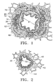
- Asthma is a disease in which (i) bronchoconstriction, (ii) excessive mucus production, and (iii) inflammation and swelling of airways occur, causing widespread but variable airflow obstruction thereby making it difficult for the asthma sufferer to breathe.
- Asthnna is a chronic disorder, primarily characterized by persistent airway inflammation. Asthma is further characterized by acute episodes of additional airway narrowing via contraction of hyper-responsive airway smooth muscle.
- the reversible aspects of COPD generally describe excessive mucus production in the bronchial tree. Usually, there is a general increase in bulk (hypertrophy) of the large bronchi and chronic inflammatory changes in the small airways. Excessive amounts of mucus are found in the airways and semisolid plugs of mucus may occlude some small bronchi. Also, the small airways are narrowed and show inflammatory changes.
- the reversible aspects of COPD include partial airway occlusion by excess secretions and airway narrowing secondary to smooth muscle contraction, bronchial wall edema and inflation of the airways
- asthma can also lead to remodeling of the airway wall (i.e., structural changes such as thickening or edema) which can further affect the function of the airway wall and influence airway hyper-responsiveness.
- Other physiologic changes associated with asthma include excess mucus production, and if the asthma is severe, mucus plugging, as well as ongoing epithelial denudation and repair.
- Epithelial denudation exposes the underlying tissue to substances that would not normally come in contact with them, further reinforcing the cycle of cellular damage and inflammatory response.
- asthma symptoms include recurrent episodes of shortness of breath (dyspnea), wheezing, chest tightness, and cough.
- dyspnea shortness of breath
- wheezing wheezing
- chest tightness chest tightness
- cough Currently, asthma is managed by a combination of stimulus avoidance and pharmacology.
- Stimulus avoidance is accomplished via systematic identification and minimization of contact with each type of stimuli. It may, however, be impractical and not always helpful to avoid all potential stimuli.
- Asthma is managed pharmacologically by: (1) long term control through use of anti-inflammatories and long-acting bronchodilators and (2) short term management of acute exacerbations through use of short-acting bronchodilators. Both of these approaches require repeated and regular use of the prescribed drugs. High doses of corticosteroid antiinflammatory drugs can have serious side effects that require careful management. In addition, some patients are resistant to steroid treatment. The difficulty involved in patient compliance with pharmacologic management and the difficulty of avoiding stimulus that triggers asthma are common barriers to successful asthma management.
- an energy transfer apparatus for transferring energy to or from an airway wall in a lung, said apparatus sized to enter a bronchus or bronchiole of a human lung and comprising: a flexible elongated body having a proximal portion and a distal portion and at least one lumen extending therebetween; a distally located expandable portion of said elongated body, said expandable portion comprising a plurality of legs terminating at a distal tip, said expandable portion having a first state and a radially-expanded second state; a plurality of energy transfer elements on said plurality of legs wherein each of said energy transfer elements is configured to contact a wall of the bronchus or bronchiole when said expandable portion is in said second state; and a deployment member configured to move said expandable portion between said first and second states, said deployment member extending at least between said expandable portion and said proximal portion of said elongated body, said deployment member
- kits comprising an energy transfer apparatus for facilitating energy transfer into a mass of airway tissue, said apparatus having the construction of the above first aspect of the present invention, and a generator configured to deliver energy to said energy transfer apparatus.
- variations of the inventive device are intended for treating airway tissue within the lungs by transfer of energy into the walls of the airway to induce plugging of the airway, to prevent the airway from being able to constrict, to increase the inner airway diameter, or to reduce resistance to flow through the airway.
- the variations are particularly directed to the treatment of the airways in the lungs to reduce the effects of asthma or other lung disease.
- One variation of the invention includes the transfer of energy to the airway wall via the application of heat.
- the variations of the inventive device decrease airway responsiveness and airway resistance to flow which may augment or replace current management techniques.
- an energy transfer apparatus for treating conditions of the lungs by decreasing airway responsiveness includes transferring energy into an airway wall to alter the airway wall in such a manner that the responsiveness of the airway is reduced.
- the inventive device is an energy transfer apparatus which facilitates energy transfer with a mass of tissue within the airways of a lung.
- the inventive device is sized to enter the bronchus or bronchiole of a human lung to conduct energy transfer with the airway tissue therein.
- the inventive device may also be sized to fit within a bronchoscope.
- the bronchoscope may have a channel with a diameter of preferably 2 mm or less.
- a variation of the inventive device includes a flexible elongated body having a proximal portion and a distal portion with a lumen extending between the proximal and distal portions.
- the flexible elongated body may be of sufficient stiffness to pass through a seal of a working channel of a bronchoscope and allow operation of the device through the working channel seal.
- the device includes an expandable portion that is adjacent to a distal portion of the elongated body.
- the expandable portion has a first state, e.g., a size, and a second state where the second state is radially expanded in size from the elongated body.
- the device may include a temperature detecting element which is placed near to the expandable portion.
- the device also includes at least one energy transfer element at an exterior of the expandable portion, where the energy transfer elements are configured to contact the wall of the bronchus or bronchiole when the expanded portion is in an expanded state.
- the device also includes a deployment member that is configured to move the expandable portion between the first and second radially expanded states.
- the deployment member may extend between the expandable portion and the proximal portion of the elongated body.
- the inventive device may further include a distal tip located at a distal end of the apparatus.
- One variation of the inventive device includes an expandable portion that has a diameter of less than 15 mm when in a second expanded state.
- Another variation of the invention includes an expandable portion which includes pre-shaped tines.
- Such tines are configured to be in a first state within an elongated body and, when advanced out of the elongated body, to expand into a second expanded state.
- the tines may be connected to each other with an expanding element to prevent the tines from entering multiple airways at a bifurcation within the lung.
- Another variation of the invention includes an expandable portion comprised of a balloon.
- This variation of the invention may include the use of a fluid which may expand the balloon into the second state.
- Yet another variation of this invention includes the use of a heat generating element in the balloon which conducts heat to the fluid to heat an exterior of the balloon. In this variation, the exterior of the balloon serves as the energy transfer element
- a further variation of the inventive device includes an expandable portion which comprises a plurality of legs which forms a basket.
- the legs of this variation may extend from a proximal joint that is found at an intersection of a distal portion of the elongated body to a distal joint that is adjacent to a distal tip.
- Each leg may have a center that is substantially parallel to the elongated body so that there is sufficient contact between the airway walls and the parallel portion of the leg.
- the center that is substantially parallel is usually referred to as the active region of the leg.
- the legs of this variation may be spaced around a circumference of the elongated body to form a basket.
- the legs of this variation may have a circular cross section or a rectangular cross section, or a non-axisymmetric cross section.
- the cross sections may be chosen to allow ready deployment from a first state to a second expanded state while resisting out-of-plane bending which may distort the spacing of the legs or the contact of electrodes with the airway surface.
- One variation of the invention includes a basket in which the distance between the proximal and distal joint is less than 35 mm when the basket is not expanded.
- Another variation of this invention includes a basket that comprises four or five legs. In this case, the legs may be placed evenly around a circumference of the elongated body.
- the legs may be found at intervals of 90 or 72 degrees.
- Other variations of the invention include devices having less than four legs or more than five legs.
- Another variation of this inventive device includes placing a temperature detecting element on one or on more legs. In this variation, the temperature of one leg may be monitored or the temperature of several legs may be independently monitored to control the energy delivery. In a further variation, multiple temperature sensing elements may be combined with independent control of energy to each leg. Both of these variations may also apply to a variation of the device having pre-shaped tines.
- the legs may be soldered or made to adhere using adhesives to the elongated body at the proximal and distal ends.
- Another variation of the invention includes a multi-lumen elongated body into which a portion of each leg is inserted. It is also contemplated that an elongated member may be reinforced via a reinforcing member. Such a reinforcing member may include a coiled or braided wire, polymeric insert, or any other similar reinforcing member.
- the energy transfer element of the invention may include an element that directly heats tissue by delivering current such as an RF based electrode.
- the RF electrode may be either bipolar or monopolar or a heated element that conductively heats tissue.
- the frequency of the RF may be selected to be in the 400 kHz range or any other standard medical range used in electro-surgical applications.
- the heated element may use AC or DC current to resistively heat the element.
- RF energy may also be used to inductively or resistively heat the element.
- An indirect method of heating includes a resistively heated element that conducts heat to the expandable portion or directly to the airway.
- the invention may also include a combination of the types of electrodes mentioned above.
- each of the energy transfer elements may be a RF electrode that is attached to each leg.
- the electrode may be fastened by a heat shrink fastener.
- a temperature detecting element may be placed on the leg and underneath the fastener.
- a resistance heating element may be coiled around a portion of the leg.
- a temperature detecting element may be placed underneath the coil.
- Other examples of the energy transfer element include a polymeric heating element, an electrically conductive paint, or a printed flex circuit which are on a portion of the leg.
- Another variation employs the basket leg itself as either a RF electrode or a heated element. In such cases, the temperature sensing element may be attached directly to a basket leg by soldering, welding, adhesive bonding, or other means or member.
- Another variation of the invention includes a sheath slidably coupled to and exterior to the expandable portion.
- the expandable portion may be resilient and self-expand into the second state when no longer confined by the sheath. For example, the sheath may be withdrawn in a proximal direction or the expandable portion may be advanced out of the sheath.
- Yet another variation of the invention includes a deployment member comprising a handle adjacent to a proximal end of the elongated body.
- the elongated body may be slidably attached to the handle.
- the deployment member may also comprise a wire that extends from the handle through the lumen of the elongated body and is fixedly attached to the distal tip. This wire provides a current to the energy transfer members.
- the elongated body, the wire, and the distal tip may be slidably moveable in a distal and proximal direction.
- This variation of the deployment member may also include a stop configured to prevent distal movement of the wire beyond a deployment point. In this variation, beyond the deployment point, movement of the elongated body against the non-moving distal tip causes the expansion member to expand from a first state into a second expanded state.
- a deployment member comprising a sheath that covers the elongated member and expandable portion and a handle at a proximal end of the sheath.
- the sheath may be slidably attached to the handle while the elongated member is rigidly attached to the handle.
- a wire may extend from said handle to a distal tip through a lumen of the elongated member.
- the variation may include a first control member attached to the sheath and slidably attached to the handle where proximal movement of the first control member causes the sheath to retract on the elongated member and uncover the expandable portion.
- This variation may also include a second control member which is attached to the wire where proximal movement of the second control member causes the distal tip and the expandable portion to retract against the non-moving elongated member and causes the expandable portion to radially expand into a second state.
- Another variation of the invention includes a deployment member having force compensation or deflection limiting stops to prevent over-expansion of the expandable member when deployed within the body.
- a variation of the invention includes placing a sheath exterior to the elongated body and expandable portion such that the expandable portion is placed within the sheath in a first unexpanded state. When the expandable portion is no longer restrained by the sheath, the expandable portion expands into its second state.
- the invention may also include a control member moveably secured to the handle where the member is configured to advance the elongated body and the wire in the distal and proximal directions.
- Another variation of the invention includes a detent means for maintaining the elongated body distally of the deployment point.
- the control member may also be configured to frictionally maintain the elongated body distally of the deployment point. In these cases, the expandable portion will be in the second expanded state.
- Other variations of the inventive device may include use of levers, control wheels, or screw mechanisms in place of a control member.
- Another variation of the inventive device includes an atraumatic distal tip that may be configured to prevent gouging of the airway tissue.
- the distal tip may have a redundant joint to prevent separation of the tip from the apparatus.
- the distal tip may also be sized to fit within or through a bronchoscope.
- the deployment member comprises a central wire extending from the distal tip to the proximal portion of the device.
- a temperature detecting element may be attached to the wire.
- the inventive device may also be radiopaque or may have radiopaque elements.
- Another variation of the invention includes providing a steering member in the device to deflect the distal tip of the apparatus in a desired direction.
- the vision system may include a fiber-optic cable or a CCD chip.
- Another variation of the invention includes providing a power supply configured to deliver energy through the energy transfer elements to the airway walls.
- the power supply may be configured to include a high temperature shut off or one which shuts down if a minimum temperature is not detected within a predetermined time or if a minimum temperature slope is not detected during a predetermined time.
- the invention further includes a kit comprising an energy transfer apparatus for facilitating energy transfer into a mass of airway tissue and a generator configured to delivery energy to the energy transfer apparatus.
- the kit may further include a bronchoscope as may any of the other inventive variations.
- the invention further includes an energy transfer apparatus for facilitating energy transfer into a mass of airway tissue within a lung, the energy transfer apparatus having been rendered sterile for the purposes of prevention of infection of the lung.
- the present invention may be used for a treatment of asthma or other constriction or spasm of a bodily conduit by application of energy.
- the treatment reduces the ability or propensity of the airway to contract, reduces plugging of the airway, increases the inner airway diameter, and/or reduces resistance to flow through the airway.
- the invention relates to improving airflow through the airways of a lung having reversible obstructive pulmonary disease. It is intended that the invention is applicable to any aspect of reversible obstructive pulmonary disease, including but not limited to asthma.
- One way of improving airflow is to decrease the resistance to airflow within the lungs. There are several approaches to reducing this resistance, including but not limited to reducing the ability of the airway to contract, increasing the airway diameter, reducing the inflammation of airway tissues, and/or reducing the amount of mucus plugging of the airway.
- the present invention includes a treatment device for advancement into the lung to treat the lung by using energy to at least reduce the ability of the lung to produce at least one symptom of reversible obstructive pulmonary disease.
- An energy treatment applicable to the inventive apparatus reduces the ability of the airways to narrow or to reduce in diameter due to airway smooth muscle contraction.
- This treatment reduces the ability of the smooth muscle to contract thereby lessening the seventy of an asthma attack.
- the reduction in the ability of the smooth muscle to contract may be achieved by treating the smooth muscle itself or by treating other tissues which in turn influence smooth muscle contraction or the response of the airway to the smooth muscle contraction.
- Treatment may also reduce airway responsiveness or the tendency of the airway to narrow or to constrict in response to a stimulus.
- the amount of smooth muscle surrounding the airway can be reduced by exposing the smooth muscle to energy which either kills the muscle cells or prevents these cells from replicating.
- the reduction in smooth muscle reduces the ability of the smooth muscle to contract and to narrow the airway during a spasm.
- the reduction in smooth muscle and surrounding tissue has the added potential benefit of increasing the caliber or diameter of the airways, this benefit reduces the resistance to airflow through the airways.
- the device used in the present invention may also eliminate smooth muscle altogether by damaging or destroying the muscle.
- the elimination of the smooth muscle prevents the contraction or spasms of hyper-reactive airways of a patient having reversible obstructive pulmonary disease. By doing so, the elimination of the smooth muscle may reduce some symptoms of reversible obstructive pulmonary disease.
- the ability of the airway to contract can also be altered by treatment of the smooth muscle in particular patterns.
- the smooth muscle is arranged around the airways in a generally helical pattern with pitch angles ranging from about -38 to about +38 degrees.
- the treatment of the smooth muscle in appropriate patterns interrupts or cuts through the helical pattern of the smooth muscle at a proper pitch and prevents the airway from constricting.
- This procedure of patterned treatment application eliminates contraction of the airways without completely eradicating smooth muscle and other airway tissue.
- a pattern for treatment may be chosen from a variety of patterns including longitudinal or axial stripes, circumferential bands, helical stripes, and the like as well as spot patterns having rectangular, elliptical, circular or other shapes. The size, number, and spacing of the treatment bands, stripes, or spots are chosen to provide a desired clinical effect of reduced airway responsiveness while limiting insult to the airway to a clinically acceptable level.
- the patterned treatment of the tissues surrounding the airways with energy provides various advantages.
- the careful selection of the portion of the airway to be treated allows desired results to be achieved while reducing the total healing load.
- Patterned treatment can also achieve desired results with decreased morbidity, preservation of epithelium, and preservation of a continuous or near continuous ciliated inner surface of the airway for mucociliary clearance.
- the pattern of treatment may also be chosen to achieve desired results while limiting total treatment area and/or the number of airways treated, thereby improving speed and ease of treatment.
- Application of energy to the tissue surrounding the airways may also cause the DNA of the cells to become cross linked.
- the treated cells with cross linked DNA are incapable of replicating. Accordingly, over time, as the smooth muscle cells die, the total thickness of smooth muscle decreases because of the inability of the cells to replicate.
- the programmed cell death causing a reduction in the volume of tissue is called apoptosis.
- This treatment does not cause an immediate effect but causes shrinking of the smooth muscle and opening of the airway over time and substantially prevents re-growth.
- the application of energy to the walls of the airway may also be used to cause a cross linking of the DNA of the mucus gland cells thereby preventing them from replicating and reducing excess mucus plugging or production over time.
- the ability of the airways to contract may also be reduced by altering mechanical properties of the airway wall, such as by increasing stiffness of the wall or by increasing parenchymal tethering of the airway wall. Both of these methods increase the strength of the airway wall and further oppose contraction and narrowing of the airway.
- One way to increase stiffness is to induce fibrosis or a wound healing response by causing trauma to the airway wall by delivery of therapeutic energy to the tissue in the airway wall.
- the energy is preferably delivered in such a way that it minimizes or limits the intra-luminal thickening that may occur.
- the mucosal layer includes the epithelium, its basement membrane, and the lamina basement, a subepithelial collagen layer.
- the submucosal layer may also play a role in airway folding. As an airway narrows, its perimeter remains relatively constant, with the mucosal layer folding upon itself. As the airway narrows further, the mucosal folds mechanically interfere with each other, effectively stiffening the airway. In asthmatic patients, the number of folds is fewer and the size of the folds is larger, and thus, the airway is free to narrow with less mechanical interference of mucosal folds than in a healthy patient. Thus, asthmatic patients have a decrease in airway stiffness and the airways have less resistance to narrowing.
- the mucosal folding in asthmatic patients can be improved by treatment of the airway in a manner which encourages folding.
- a treatment will increase the number of folds and/or decrease the size of the folds in the mucosal layer.
- treatment of the airway wall in a pattern such as longitudinal stripes can encourage greater number of smaller mucosal folds and increase airway stiffness.
- the mucosal folding can also be increased by encouraging a greater number of smaller folds by reducing the thickness of the mucosa and/or submucosal layer.
- the decreased thickness of the mucosa or submucosa may be achieved by application of energy which either reduces the number of cells in the mucosa or submucosal layer or which prevents replication of the cells in the mucosa or submucosal layer.
- a thinner mucosa or submucosal layer will have an increased tendency to fold and increased mechanical stiffening caused by the folds.
- the parenchyma surrounds airways and includes the alveolus and tissue connected to and surrounding the outer portion of the airway wall.
- the parenchyma includes the alveolus and tissue connected to and surrounding the cartilage that supports the larger airways.
- the parenchyma provides a tissue network which connects to and helps to support the airway. Edema or accumulation of fluid in lung tissue in patients with asthma or COPD is believed to decouple the airway from the parenchyma reducing the restraining force of the parenchyma which opposes airway constriction. Energy can be used to treat the parenchyma to reduce edema and/or improve parenchymal tethering.
- the applied energy may be used to improve connection between the airway smooth muscle and submucosal layer to the surrounding cartilage, and to encourage wound healing, collagen deposition, and/or fibrosis in the tissue surrounding the airway to help support the airway and prevent airway contraction.
- Hypertrophy of smooth muscle, chronic inflammation of airway tissues, and general thickening of all parts of the airway wall can reduce the airway diameter in patients with reversible obstructive pulmonary disease.
- Increasing the overall airway diameter using a variety of techniques can improve the passage of air through the airways.
- Application of energy to the airway smooth muscle of an asthmatic patient can debulk or reduce the volume of smooth muscle. This reduced volume of smooth muscle increases the airway diameter for improved air exchange.
- Reducing inflammation and edema of the tissue surrounding the airway can also increase the diameter of an airway.
- Inflammation and edema (accumulation of fluid) of the airway are chronic features of asthma.
- the inflammation and edema can be reduced by application of energy to stimulate wound healing and regenerate normal tissue.
- Healing of the epithelium or sections of the epithelium experiencing ongoing denudation and renewal allows regeneration of healthy epithelium with less associated airway inflammation.
- the less inflamed airway has an increased airway diameter both at a resting state and in constriction.
- the wound healing can also deposit collagen which improves parenchymal tethering.
- Inflammatory mediators released by tissue in the airway wall may serve as a stimulus for airway smooth muscle contraction.
- Therapy that reduces the production and release of inflammatory mediator can reduce smooth muscle contraction, inflammation of the airways, and edema.
- inflammatory mediators are cytokines, chemokines, and histamine.
- the tissues which produce and release inflammatory mediators include airway smooth muscle, epithelium, and mast cells. Treatment of these structures with energy can reduce the ability of the airway structures to produce or release inflammatory mediators. The reduction in released inflammatory mediators will reduce chronic inflammation, thereby increasing the airway inner diameter, and may also reduce hyper-responsiveness of the airway smooth muscle.
- a further process for increasing the airway diameter is by denervation.
- a resting tone of smooth muscle is nerve regulated by release of catecholamines.
- the resting tone of the smooth muscle is reduced, and the airway diameter is increased. Resting tone may also be reduced by directly affecting the ability of smooth muscle tissue to contract.
- Excess mucus production and mucus plugging are common problems during both acute asthma exacerbation and in chronic asthma management.
- Excess mucus in the airways increases the resistance to airflow through the airways by physically blocking all or part of the airway.
- Excess mucus may also contribute to increased numbers of leukocytes found in airways of asthmatic patients by trapping leukocytes. Thus, excess mucus can increase chronic inflammation of the airways.
- One type of asthma therapy involves treatment of the airways with energy to target and reduce the amount of mucus producing cells and glands and to reduce the effectiveness of the remaining mucus producing cells and glands.
- the treatment can eliminate all or a portion of the mucus producing cells and glands, can prevent the cells from replicating or can inhibit their ability to secrete mucus. This treatment will have both chronic benefits in increasing airflow through the airways and will lessen the severity of acute exacerbation of the symptoms of reversible obstructive pulmonary disease.
- a device 30 of the present invention must be of a size to access the bronchus or bronchioles of the human lung.
- the device may be sized to fit within bronchoscopes, preferably, with bronchoscopes having a working channel of 2 mm or less. Also, the device should be of sufficient stiffness to fit and operate through the seal covering the working channel a bronchoscope.
- the energy may be delivered by the treatment device 30 in a variety of treatment patterns to achieve a desired response. Examples of patterns are discussed in further detail below.
- the device may, but is not necessarily, configured to deliver energy in non-intersecting strip patterns which are parallel with a central axis of an airway.
- other variations of the device may be configured to deliver energy in a torsional pattern, or in a circumferential pattern around a wall of the airway. Such configurations which may be determined to deliver energy to the airway tissue that maximize the ability of the airway to permit airflow are considered to be within the scope of this invention.
- the inventive devices include tissue contacting electrodes configured to be placed within the airway. These devices can be used for delivering radio frequency in either a monopolar or a bipolar manner or for delivering other energy to the tissue, such as conducted heat energy from resistively heated elements.
- tissue contacting electrodes configured to be placed within the airway. These devices can be used for delivering radio frequency in either a monopolar or a bipolar manner or for delivering other energy to the tissue, such as conducted heat energy from resistively heated elements.
- monopolar energy delivery one or more electrodes of the treatment device are connected to a single pole of the energy source 32 and an optional external electrode 44 is connected to an opposite pole of the energy source.
- bipolar energy delivery multiple electrodes are connected to opposite poles of the energy source 32 and the external electrode 44 is omitted.
- the external electrode 44 depicted in FIG. 4 is not required in the case of bipolar energy delivery.
- the number and arrangement of the electrodes may vary depending on the pattern of energy delivery desired.
- the treatment device of FIG. 11 may also be used to deliver indirect radio frequency, microwave energy, or conductive heat energy to the tissue.
- the current may be AC or DC current or in the case of AC, the current may be delivered in the RF range.
- the use of RF provides an added safety feature of minimizing the possibility of harm to the patient caused by escaped current.
- the device may also use a combination of any of the energy transferring element configurations described herein.
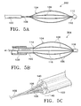
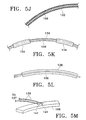
- the treatment device 302 of FIG. 5A which is not in accordance with the present invention, includes an elongated member 102 for delivering an expandable member 104 to a treatment site.
- the expandable member 104 may have a plurality of energy transfer elements (not illustrated) which are placed on a plurality of basket legs 106 to transfer energy at the treatment site.
- the expandable member comprises a basket 104 which is defined by a number of basket legs 106.
- the basket legs 106 are formed from a plurality of elements which are soldered or otherwise connected together at two connection areas, a proximal joint 108 and a distal joint 110.
- a desirable length of the basket 104, or the expandable portion of any variation of the invention depends upon numerous factors.
- One consideration in determining a desired length of the expandable member, e.g., the distance between the joints of the basket, of the inventive device is related to the dimension of the target area or treatment region. For instance, some other factors include considerations of minimizing the amount of the expandable portion which is distal to the treatment region for optimized access, minimizing the amount of the expandable portion that is proximal to the treatment region for visualization and access concerns, and setting a desirable length of the expandable portion that will contact a sufficient portion of the treatment region during each application of the device.
- a compromise of such factors along with other considerations provides a desirable length for the expandable portion of the device.
- the distance between the distal and, proximal joints of the basket is less than 35 mm when the basket is in a first unexpanded state.
- the legs 106 may be selected from a material that allows the basket to expand without plastic deformation.
- the legs may comprise a stainless steel, or a shape memory/superelastic alloy such as a nitinol material.
- the basket legs 106 may have a rectangular cross section in those variations where the legs 106 are formed from ribbons, or the legs 106 may have a circular cross section in those variations where the legs are formed from wires.
- the legs 106 may also have other cross section as desired. It is also contemplated that the legs 106 need not all have similar cross sections.
- the cross section of each of the legs 106 in a basket 104 may be individually chosen to optimize such factors as the resilience of the basket 104, or to optimize energy transfer characteristics.
- the legs may also have a variable cross section along the length of the basket.
- the illustrated device 302 has a basket 104 comprising of four legs 106. It is preferred that the legs 106 are spaced at equal intervals around the expandable member or basket 104. For example, in devices having four legs 106, the legs 106 are preferably, but not necessarily spaced at approximately 90 degree intervals around the basket 104. In devices having five legs 106, the legs 106 may be spaced at approximately 72 degree intervals. Variations of the invention include devices having less than four legs or more than five legs. It is thought that the most effective number of legs is a compromise based on the size of the target airway, contact surface between the leg 106 and airway wall, and the maximum outer diameter of the elongated member 102.
- the proximal 108 and/or distal 110 joints may also contain adhesive to bind the legs 106.
- the basket legs 106 between the proximal 108 and distal joint 110 are formed into the basket shape 104 so that arch shaped portions of the basket legs 106 will contact the walls of an airway to facilitate energy transfer.
- the basket legs 106 may have a more oblong shape or sharper bends to allow for a more parallel leg surface area that contacts the target tissue.
- Each leg 106 may have a center that is substantially parallel to the elongated body so that there is sufficient contact between the airway walls and the parallel portion of the leg 106. The center that is substantially parallel is usually referred to as the active region of the leg 106.
- the length of the basket 104 between the proximal and distal 110 joints may be less than 35 mm when the basket 104 is in a first unexpanded state.
- the legs 106 may be coated with an insulating material (not shown) except at the tissue contact points. Alternatively, the legs 106 of the basket 104 may be exposed while the proximal 108 and distal joint 110 are insulated.
- the basket 104 is formed of a resilient material which allows the distal end of the device 302 to be confined by a sheath (not shown) for delivery of the device 302 to the treatment site and allows the basket 104 to return to its original basket shape upon deployment
- a variation of the invention is that the basket self-expands from a first state to a second expanded state upon the removal of any constraining or restrictive member such as a sheath (not shown).
- the inventive device 302 is preferably configured such that the basket legs 106 have sufficient resilience to come into contact with the airway walls for treatment.
- FIG. 5A illustrates a device 302 that is not in accordance with the present invention and in which a distal end of the device 302 is provided with a distal tip 112 that can have a radius to facilitate insertion of the device 302 into the lungs and also to minimize the possibility of causing trauma to surrounding tissue.
- the tip 112 is preferably sized to prevent the gouging of airway by the sheath.
- the design of the distal tip is selected to be atraumatic.
- the size of the tip may be selected to be large enough to prevent the sheath from gouging airways yet small enough to pass in and out of a bronchoscope.
- FIG. 5B illustrates a variation of device 302 which is in accordance with the present invention and which has basket legs 108 connected to a distal end 114 of the elongated member 102 and forming a basket 104.
- a proximal joint is found at the distal end 114 of the elongated member 102.
- the basket 104 is expanded radially, to its second state, during use to ensure contact between the energy transfer elements (not shown) and the airway walls (not shown) by, for example, pulling on a center pull wire 116 which is connected to a distal tip 118 of the expandable portion 104.
- the center pull wire 116 may extend through a lumen of the elongated member 102 towards a proximal portion (not shown) of the elongated member 102.
- the center pull wire 116 is configured to deliver current to the energy transfer elements found on the expandable member 104.
- the inventive device 302 may be delivered to a treatment site through a delivery sheath 120 and may be drawn along or moved axially along the airway to treat the airway in a pattern of longitudinal or helical stripes.
- the basket 104 may be resilient or self-expanding (e.g., see FIG. 5A) to expand to a second expanded state or the basket 104 may require an expanding force (e.g., see FIG 5B).
- FIG. 5B An example of this variation of the inventive device 304 is shown in FIG. 5B.
- the basket 104 may be resilient and the sheath 120 may comprise the deployment member.
- the basket 104 contracts within the sheath 120 and assumes a first state.
- the basket 104 upon advancing the basket 104 and elongate body 102 out of the sheath 120, the basket 104 may resiliently assume a second expanded state.
- the basket 104 may assume a second expanded state with the aid of a wire 116. This wire may also be configured to deliver power to the energy exchange elements 106.
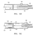
- FIG. 5C illustrates a variation of the inventive device where an elongated member 102 of is configured to have a plurality of lumens 140 so that each of the basket legs 106 are isolated within the lumens 140 of the elongated member 102 until the legs 106 exit the elongated member 102 and connect at a proximal joint 108.
- the invention may have basket legs 106 selected with a sufficient length such that the ends of each of the legs 106 extend substantially into the lumens 140. As a result of being inserted deeply within the lumen, the ends of the legs 146 would require significant travel before they exited the lumen 140. This feature provides added safety as it minimizes the risk of the basket legs 106 dislodging from the elongate member 102.
- the elongated member 102 may comprise concentric tubes (not shown) rather than multi-lumen tubes where basket legs are inserted in the annulus between the tubes. It is also contemplated that an elongated member may be reinforced with the use of a reinforcing member. Such a reinforcing member may include a coiled wire or polymeric insert.
- FIG. 5D-5I illustrate variations of the inventive device that use an expanding force to expand the basket
- FIG. 5D illustrates a deployment member of the device.
- FIG. 5E illustrates the device of FIG. 5D when the elongated member is moved in a distal direction to a deployment point.
- FIG. 5F-5G illustrates the elongated member 102, sheath 120, expandable member 104, distal tip 118, and wire 122 extending through the device.
- FIG. 5F illustrates the basket 104 in a first unexpanded state when the elongated member 102 and wire 122 are proximal of the deployment point 130.
- FIG. 5G illustrates the expansion of the basket 104 to a second expanded state as the elongated member 102 moves distally and the wire 122 is restrained at the deployment point 130.
- the deployment member may comprise a handle 124 which is adjacent to a proximal portion of an elongated member 102.
- the handle may be designed to be operated by a single hand, either right or left.
- the handle may also have a control switch for operation of the device. Such a switch could control the power supply attached to the device as well.
- the handle may be configured to determine the position of the device within a human body as the device is advanced to a target site. For example, marks or indicia on the handle or even a readout could provide information to the user as to the relative deployment state of the expandable member.
- a sensor may be placed on the handle 124, this sensor may be used to determine the position of the expandable member.
- the handle 124 may control the expandable member using force compensation (e.g., a spring, etc.) or deflection limiting stops to control the expansion of the expandable member.
- force compensation e.g., a spring, etc.
- deflection limiting stops to control the expansion of the expandable member.
- an elongated member 102 may be slidably mounted to the handle.
- the variation of the invention depicted in these Figures may also, but does not necessarily, include a sheath 120 exterior to the elongated body 102.
- a wire 122 extends from the handle through the elongated member 102 and may be attached to a distal tip 118 of the device.
- the wire 122, elongated member 102, and distal tip (not shown) are slidably moveable in both a distal and proximal directions.
- the handle may also include a stop 126 which prevents the wire 122 from moving distally beyond a deployment point 130.
- the stop 126 may be connected to a spring (not shown) to limit the expansion of the expandable member upon reaching a pre-determined force.
- the handle 124 may include a control member 128 that is moveably attached to the handle 124 for moving the elongated member 102 in a distal/proximal direction.
- the handle 124 in the figures is depicted to have a control member 128 as illustrated, other variations of control members are also contemplated to be within the scope of this invention.
- a handle 124 may include other configurations, such as lever, thumb-wheel, screw-mechanism, ratchet mechanism, etc., which are attached to the handle 124 to provide control actuation for the expandable member.
- FIG. 5E illustrates a variation of the inventive device when the elongated member 102 and wire 122 are moved in a distal direction.
- a stop 126 prevents the wire 122 from moving distally of a deployment position 130.
- This illustration further illustrates a variation of the invention where the stop 126 is attached to springs 127 which provide force compensation for the expandable member on the device.
- a control member 128 may have a stop which limits its travel along a handle 124. Such a stop is an example of a deflection limiting mechanism which controls the movement of the control member 128, thus controlling the extent of the expansion of the expandable member.
- FIG. 5F illustrates the invention when the expandable member or basket 104 is in a first unexpanded state.
- the wire 122 is attached to a distal tip 118 of the device and both are prevented from distal movement when the wire 122 is in the deployment position 130. Therefore, as depicted in FIG. 5G, movement of the elongated member 102 in a distal direction against a distal tip 118, that is restrained by a wire 122, causes a basket 104 to compress between the advancing elongated member 102 and the stationary distal end 118. Thus, the basket 104 is forced outward and radially expands into a second expanded state.
- the wire 122 is used to transfer energy to the energy transfer elements found on the basket 104, and may also be used to transfer energy from those elements. Also, it is contemplated that the wire 122 may be a wire, a ribbon, a tube, or of any other equivalent structure. Also contemplated, but not shown, is a detent means for maintaining the elongated member in a distal position to expand the basket 104 against the distal tip 118 without the need for continual applied force by a user of the device. Also contemplated is a ratchet member, or friction member to maintain the basket 104 in the expanded state.
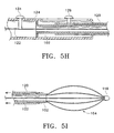
- FIG. 5H illustrates another variation of a deployment member.
- a sheath 120 may be slidably attached to a handle 124.
- the elongate member 102 is rigidly attached to the handle 124.
- the sheath 120 may be attached to a first control member 129.
- a wire 122 extends through the elongate member 102 and is attached to the distal tip of the device (not shown).
- the wire 122 may be attached to a second control member 131.
- proximal movement of the first control member 129 causes the sheath 120 to proximally retract over the elongate member 102 and uncover the expandable portion (not shown).
- Proximal movement of the second control member 131 causes the wire 122, distal joint, and expandable member to move against the non-moving elongate member 102 which causes the expandable member to expand into a second state.
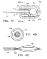
- FIG. 5J-5L illustrate examples of energy transfer elements that may be located on the expandable portion of the device.
- the basket legs 106 may function as heat exchange elements.
- the device may be configured so that the leg is an electrode or the conductive heating element.
- the leg 106 may be partially covered with an insulation only leaving an active region exposed for delivery of energy to the airways. Examples of such insulation include a heat shrink sleeve, a dielectric polymeric coating, or other material which may function as an insulator.
- FIG. 5J illustrates an example of a basket leg 106 with an energy transferring element 132 coiled around the leg 106.
- the energy transferring element uses conductive heating and comprises a resistance heating element 132 coiled around the leg 106.
- FIG. 5K illustrates a variation of the invention having an RF electrode 136 attached to the basket leg 106.
- the RF electrode 136 may be attached to the basket leg 106 via the use of a fastener 134.
- the electrode may be attached via the use of a heat shrink fastener 134, (e.g., polymeric material such as PET or polyethylene tubing).
- FIG. 5L illustrates another variation of the invention where the energy transfer element is a printed circuit 138 that is situated around the leg 106 and secured to the leg.
- energy transfer elements are a polymeric heating material, an electrically conductive paint, a resistance element spattered onto me leg in a pattern or formed on a substrate by photofabrication.
- the basket leg itself may be chosen of appropriate size and resistivity to alloy dual use as a basket and energy transfer element Many nickel-chromium alloys have both high specific resistance and significant spring-like properties.
- adhesives or other coatings may also be used to secure the energy transfer element to the basket leg 106.
- the energy transfer elements are not limited to what is illustrated in the drawings. It is also contemplated that other types of energy transfer elements may be used such as radiant, laser, microwave, and heat energy.
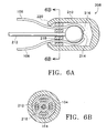
- FIG. 6A illustrates a variation of a distal tip 210 having a redundant joint.
- the distal tip 208 has a polymeric cap 210 covering the distal ends of the basket legs 106 and wire 212.
- the legs 106 are soldered 214 to the distal end of the wire 212.
- Also used to maintain the joint is an adhesive 216 substantially filling the polymeric cap 210.
- a multi-lumen piece 218 separates the legs 106 and wire 212.
- a side view of the multi-lumen piece 218 is shown in FIG. 6B.
- a multi-lumen tubing may be used for the multi-lumen piece 218.
- the ends 220 of the polymeric cap 210 may be heat formed or otherwise tapered down around the legs 106.
- the proximal joint may also be redundant
- FIG. 6C illustrates another variation of a distal tip 222 having a redundant joint
- the distal tip 222 has a polymeric cap 210 covering the distal ends of the basket legs 106 and wire 212.
- the legs 106 are soldered 214 to the distal end of the wire 212.
- Also used to maintain the joint is an adhesive 216 substantially filling the polymeric cap 210.
- a hypo-tube 224 covers the legs 106 and wire 212.
- a side view of the hypo-tube 224 is shown in FIG. 6D.
- the distal end of the hypo-tube 224 may be flared to seat a ball located on a distal end of the wire 212 and the legs 106.
- a proximal end of the hypo-tube 224 may be flared to provide greater interlock with ends 220 of the polymeric cap 210.
- the ends of the legs 106 taper outwards from the hypo-tube 224 and form an area with a diameter larger than the end of the cap 226 which may be tapered down around the legs 106 and wire 212.
- the ends 220 of the polymeric cap 210 may be heat formed or otherwise tapered down.
- FIG. 6E shows a device not in accordance with the present invention, having a hoop or ring 228 at a proximal joint of the device.
- the hoop 228 may be soldered or welded to the legs 106 and keeps the legs 106 attached even if a joint fails between the legs and me elongate member 102. Also, the hoop 228 may electrically connect the legs, preventing disconnection of single leg 106 having a temperature sensing element attached.
- the invention also includes a temperature detecting element (not shown).
- temperature detecting elements include thermocouples, infrared sensors, thermistors, resistance temperature detectors (RTDs),or any other apparatus capable of detecting temperatures or changes in temperature.
- the temperature detecting element is preferably placed in proximity to the expandable member.
- a temperature sensor may be mounted along the pull wire 116.
- a temperature sensor may be mounted between the energy transfer elements 132, 136, 138 and the leg 106.
- a temperature sensor is placed on a single basket leg 106 to provide a signal to control energy transfer.
- a temperature sensor may be placed on more than one basket leg 106, and/or on a central wire 116 to provide control for multiple areas of energy transfer.
- the temperature sensor may be placed on the inside of the basket leg 106 to protect the temperature sensor while still providing a position advantageous to determining the device temperature at the energy transfer element.
- FIG. 5M illustrates a variation of the invention having thermocouple leads 139 attached to a leg 106 of the device.
- the leads may be soldered, welded, or otherwise attached to the leg 106.
- This variation of the invention shows both leads 139 of the thermocouple 137 attached in electrical communication to a leg 106 at separate joints 141. In this case, the temperature sensor is at the surface of the leg. This variation provides in case either joint becomes detached, the circuit will be open and the thermocouple 137 stops reading temperature.
- the device may also include both of the thermocouple leads as having the same joint .
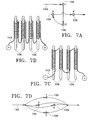
- FIG. 7A-7D illustrate variations of the device in which impedance may be varied by wiring the basket legs 106 in series or in parallel.
- FIG. 7A illustrates a series wiring diagram in which a current path 142 flows from a first leg to a second leg 106, a third leg 106, and a fourth leg 106 sequentially.
- FIG. 7B illustrates the series wiring diagram and shows a single wire 143 connecting the legs 106 in series.
- the wire 143 may, for example, extend to a distal end of the leg and wrap over itself to the proximal end of the leg 106.
- a covering (not shown) may be placed over the wire 143 wrapped leg 106 at the proximal end of the device.
- FIG. 7C illustrates another variation of a series wiring diagram.
- a wire 143 extends from the proximal end of a leg 106 to its distal end and then extends to the distal end of an adjacent leg 106 and extends back to the proximal end of the adjacent
- FIG. 7D illustrates a parallel wiring diagram in which a current path 142 flows to each leg 106.
- Series wiring has an added advantage in that all current will pass through each energy transfer element. By design, this configuration equalizes the heat dissipated at each leg through construction of legs with equal resistance. In addition, in the event of failure of any electrical connection, no energy is delivered. This provides an additional safety feature over parallel wiring.
- the electrical current may be AC or DC.
- AC may be delivered in the RF range as a safety measure additional to electrical isolation.
- DC may be used to allow a portable device powered by a battery pack or provide an energy source within the device itself.
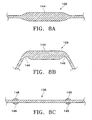
- FIG. 8A-8C illustrates variation of the legs 106 of the basket 104.
- the legs may, for example, comprise a stainless steel, or a shape memory/superelastic alloy such as a nitinol material.
- the basket legs 106 may have a rectangular cross section in those variations where the legs 106 are formed from ribbons, or the legs 106 may have a circular cross section in variations where the legs 106 are formed from wires.
- a leg 106 may be configured to have a non-axisymmetric cross-section.
- the leg may have an oval or flat cross section as well.
- the legs 106 of a basket 104 need not all have similar cross sections.
- each of the legs 106 in a basket 104 may be individually chosen to optimize such factors as the resilience of the basket 104, or to optimize energy transfer characteristics.
- FIG. 8A illustrates a top view of a basket leg 106 that has a contoured shape 144.
- the energy exchange element is not shown in the figure for clarity.
- FIG. 8B One of the purposes of such a contoured shape 144 is illustrated in FIG. 8B.
- leg 106 is configured to bend at or substantially near to points 146.
- a benefit of such a configuration is to allow a substantially parallel active surface as defined by the contour shape 144.
- the leg 106 has a region of increased diameter 148 in the case of round wire, or increased width or thickness in the case of rectangular or other non-axisymmetric wire.
- a region 106 could also be a flat wire with bumps or protrusions creating areas of increased width of the flat wire.
- This region 148 may, for example, provide a stop that assists in locating insulation, heat shrink, or other external covering around the leg 106.
- a leg 106 that consists of a composite construction.
- the leg 106 may comprise of differing materials in predetermined regions to control the bending of the leg 106 as the basket 104 expands, or the leg may be constructed of different materials to selectively control regions of deliver of energy on the leg.
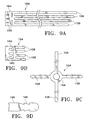
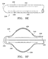
- FIG. 9A-9F illustrate additional variations of the inventive device in which the expandable member comprises a basket comprised from a single piece or sheet of material. Such a configuration could comprise an etched, machined, laser cut, or otherwise manufactured piece of metal.
- FIG. 9A illustrates a partial view of a basket 104 formed from a single piece of material. The thickness of the material is, for example 0.127 mm (.005 inches), but may vary as desired.
- the illustration of FIG. 9A shows the basket 104 prior to being wrapped about the Z direction as indicated. As shown, the legs 106 may be of varying length or they may be the same length or a combination thereof.
- the basket 104 may have a distal portion 164 or basket head 164 which may be configured to facilitate construction of the device.
- the basket head 164 may be notched 166 to obtain a desired shape as the basket is wrapped about the Z direction.
- FIG. 9B illustrates a variation of the basket head 165 being notched such that sections 165 of the material may be bent from the plane of the material to form tabs 165. Tabs 165 may be used to form mechanical joints with another part, such as a distal tip cap.
- FIG. 9C illustrates another variation of a basket 104 made from a single piece of material. In this example, the legs 106 of the basket 104 are bent in a direction orthogonal to the plane of the basket head 164. In this example, the distance between the ends of the legs 106 may be, for example, about 2.75 inches.
- FIG. 9B illustrates a variation of the basket head 165 being notched such that sections 165 of the material may be bent from the plane of the material to form tabs 165. Tabs 165 may be used to form mechanical joints with another part, such as a distal tip cap.
- FIG. 9C illustrates another
- FIG. 9D illustrates a variation of the proximal ends of the legs 106 of the basket 104.
- the proximal ends of the legs 106 may have features 168 which promote the structural integrity of me proximal joint (not shown) of the device.
- the proximal joint may be redundant.
- the ends of the legs 106 have a saw-tooth design which improve the integrity of the proxnnal joint connecting the legs 106 to the elongated member.
- the variation of FIG. 9D also illustrates a proximal end of the leg 106 as having a radius, however, the end of the leg 106 may have other configurations as required.
- the legs 106 may have a width of, for example 0.305 mm (.012 inches)and a separation of, for example 0.406 mm (.016 inches). However, these dimensions may vary as needed.
- FIG. 9E illustrates a sectional view of a variation of the inventive device in which the expandable member comprises a tube 230 having slits or cuts 232 where the area between the slits or cuts 232 comprise legs 240 of the basket
- FIG. 9F illustrates expansion of the basket of FIG. 9E.
- the legs 240 may be expanded by pulling a wire 236 that is attached to a tip 234 of the device in a proximal direction while the tube 230 remains fixed.
- the wire 236 is used to conduct energy to the basket
- the wire 236 may remain fixed as the tube 230 is advanced in a distal direction causing the legs 240 to bow outwards.
- the tube 230 may be cut or slit as required to obtain a desired number of legs or legs having a desired width.
- the tip 234 of the device may be selected to be rounded or abraumatic.
- the tip 234 may be fused, banded, soldered, welded or otherwise constructed as desired to be closed or rounded.
- the tube 230 may be selected to be conductive.
- the tube 236 may be coated or covered with an insulator material (not shown) while a portion of the legs 240 will be left exposed or uncovered. This uncovered portion comprising an active surface of the basket which facilitates energy transfer.
- electrodes 238 may be placed on the legs 240 to provide an active region that facilitates energy transfer.
- the electrode 238 may be crimped, folded, welded, painted, deposited, or otherwise located on the leg 240.
- the tube 230 may be selected to have a varying thickness (not shown) to facilitate expansion of the basket, an interior passage, rigidity of the tube and ease of expansion of the basket This variation provides advantages as the number of components making the device may be minimized and construction of the basket is simple.
- FIGS. 10 and 11 illustrate a further variation of the inventive device 326 having an expandable member 204 in a first non-expanded state and in a second expanded state.
- FIG. 10 illustrates the device as having one or more loop shaped electrodes 204 connected to an elongated member 102. In the unexpanded position shown in FIG. 10, the loop of the electrode 204 lies along the sides of a central core 206. A distal tip of the loop electrode 204 is secured to the core 206 and to a distal tip 208. The core 206 may be slidable in a lumen of the elongated member 102.
- the electrode 204 is expanded by pulling the core 206 proximally with respect to the elongated member 102, as shown in FIG. 11.
- the electrode 204 or the core 206 may be spring biased to return to a configuration of FIG. 11 when a constraining force is removed. This constraining force may be applied by a delivery sheath or bronchoscope through which the inventive device 326 is inserted or by a releasable catch.
- the treatment of the tissue in the airway walls by transfer of energy according to the present invention provides improved long term relief from asthma symptoms for some asthma sufferers.
- some amount of smooth muscle or mucus gland cells which were not affected by an initial treatment may regenerate and treatment may have to be repeated after a period of time such as one or more months or years.
- the airways which are treated with the device according to the present invention are preferably 1 mm in diameter or greater, more preferably 3 mm in diameter.
- the devices are preferably used to treat airways of the second to eighth generation, more preferably airways of the second to sixth generation.
- the present invention has been described in detail with respect to devices for the treatment of airways in the lungs, it should be understood that the present invention may also be used for treatment of other body conduits.
- the treatment system may be used for reducing smooth muscle and spasms of the esophagus of patients with achalasia or esophageal spasm, in coronary arteries of patients with Printzmetal's angina variant, for ureteral spasm, for urethral spasm, and irritable bowel disorders.
- the devices describe herein provide a more effective and/or permanent treatment for asthma than the currently used bronchodilating drugs, drugs for reducing mucus secretion, and drugs for decreasing inflammation.
- the inventive device may also include a steering member configured to guide the device to a desired target location.
- this steering member may deflect a distal tip of the device in a desired direction to navigate to a desired bronchi or bronchiole.
- a vision system may comprise a fiber optic cable which allows a user of the device to guide a distal tip of the device to its desired location.
- the vision system may include a CCD chip.
- a power supply for providing energy as described above.
- the power supply provides the energy to be delivered to airway tissue via the energy transfer device. While the main goal of the power supply is to deliver enough energy to produce the desired effect, the power supply must also deliver the energy for a sufficient duration such that the effect persists. This is accomplished by a time setting which may be entered into the power supply memory by a user.
- a power supply may also include circuitry for monitoring parameters of energy transfer: (for example, voltage, current, power, impedance, as well as temperature from the temperature sensing element), and use this information to control the amount of energy delivered.
- parameters of energy transfer for example, voltage, current, power, impedance, as well as temperature from the temperature sensing element
- a power supply may also include control modes for delivering energy safely and effectively. Energy may be delivered in open loop power control mode for a specific time duration. Energy may also be delivered in temperature control mode, with output power varied to maintain a certain temperature for a specific time duration. In the case of RF energy delivery via RF electrodes, the power supply may operate in impedance control mode.
- the power supply will operate at up to a 75°C setting.
- the duration must be long enough to produce the desired effect, but as short as possible to allow treatment of all of the desired target airways within a lung. For example, 5 to 10 seconds per activation (while the device is stationary) is preferred. Shorter duration with higher temperature will also produce acceptable acute effect.
- the power supply may include control algorithms to limit excessive thermal damage to the airway tissue. For example, in order to stop delivery of energy in the event of contact between airway tissue and device legs having temperature sensing capabilities, an algorithm may be employed to shut down energy delivery if the sensed temperature does not rise by a certain number of degrees in a pre-specified amount of time after energy delivery begins.
- Another way to stop energy delivery includes shutting down a power supply if the temperature ramp is not within a predefined rage at any time during energy delivery.
- Other algorithms include shutting down a power supply if a maximum temperature setting is exceeded or shutting down a power supply if the sensed temperature suddenly changes, such a change includes either a drop or rise, this change may indicate failure of the temperature sensing element.
- a variation of the invention includes configuring each energy exchange element independently to provide selective energy transfer radially about the device.
- another variation of the invention includes providing feedback control to determine the impedance of the airway to determine the power required by a power supply. Again, as discussed above, the feedback control could also be used to determine the size of the airway in which the device is positioned.
- the treatment of an airway with the treatment device may involve placing a visualization system such as an endoscope or bronchoscope into the airways.
- the treatment device is then inserted through or next to the bronchoscope or endoscope while visualizing the airways.
- the visualization system may be built directly into the treatment device using fiber optic imaging and lenses or a CCD and lens arranged at the distal portion of the treatment device.
- the treatment device may also be positioned using radiographic visualization such as fluoroscopy or other external visualization means.
- the treatment device which has been positioned with a distal end within an airway to be treated is energized so that energy is applied to the tissue of the airway walls in a desired pattern and intensity.
- the distal end of the treatment device may be moved through the airway in a uniform painting like motion to expose the entire length of an airway to be treated to the energy.
- the treatment device may be passed axially along the airway one or more times to achieve adequate treatment.
- the "painting-like" motion used to exposed the entire length of an airway to the energy may be performed by moving the entire treatment device from the proximal end either manually or by motor. Alternatively, segments, stripes, rings or other treatment patterns may be used.
- the energy is transferred to or from an airway wall in the opening region of the airway, preferably within a length of approximately two times the airway diameter or less, and to wall regions of airways distal to bifurcations and side branches, preferably within a distance of approximately twice the airway diameter or less.
- the invention may also be used to treat long segments of unbifurcated airway.
- a method of use of the device of the present invention includes advancing a treatment device into a lung and treating the lung with the device to, at least, reduce the ability of the lung to produce at least one symptom of reversible obstructive pulmonary disease.
- the treatment may reduce all of the symptoms of reversible obstructive disease.
- the treatment may be selected to address specific symptoms of the disease.
- the treatment of the lung may sufficiently reduce the symptoms of reversible obstructive pulmonary disease such that the patient is able to function as those free from the disease.
- the treatment may be such that the symptoms are reduced to allow the patient to more easily manage the disease.
- the effects of me treatment may be either long term or short term with repeating treatment necessary to suppress the symptoms.
- the methods described herein may be performed while the lung is experiencing natural symptoms of reversible obstructive pulmonary disease.
- One such example is where an individual, experiencing an asthma attack, or acute exacerbation of asthma or COPD, undergoes treatment to improve the individual's ability to breath. In such a case, the treatment, called 'rescue,' seeks to provide immediate relief for the patient.
- the method may also include the steps of locating one or more treatment sites within an airway of the lung, selecting one of the treatment sites from the locating step and treating at least one of the selected treatment sites. As mentioned above, these steps may be, but are not necessarily, performed while the lung is experiencing symptoms of reversible obstructive pulmonary disease.
- the methods of use may further comprise the step of stimulating the lung to produce at least one artificially induced symptom of reversible obstructive pulmonary disease.
- stimulation of the lung would preferably increase the resistance to airflow within the lung, constrict airways within the lung, inflame/irritate airway tissues, increase edema and/or increase the amount of mucus plugging of the airway.
- Stimulation of the lung may occur at any point during the procedure or before the procedure.
- the lung may be stimulated either prior to or after, the step of locating a treatment site. If the lung is stimulated prior to the step of locating a treatment site, the reaction of the stimulated tissue within the lung may be useful in determining which locations are to be selected as treatment sites.
- the lung tissue or airway tissue within the lung may be stimulated by a variety of methods including but not limited to pharmacological stimulation, (e.g., histamine, methacholine, or other brouchoconstricting agents, etc.), electrical stimulation, mechanical stimulation, or any other stimuli causing obstructive pulmonary symptoms.
- electrical stimulation may comprise exposing airway tissue to electrical field stimulation.
- An example of such parameters include 15 VDC, 0.5 ms pulses, 0.5-16 Hz, and 70 VDC, 2-3 ms pulses, 20 HZ.
- the locating step described above may be performed using a non-invasive imaging technique, including but not limited to, a bronchogram, magnetic resonance imaging, computed tomography, radiography (e.g., x-ray), and ventilation perfusion scans.
- a non-invasive imaging technique including but not limited to, a bronchogram, magnetic resonance imaging, computed tomography, radiography (e.g., x-ray), and ventilation perfusion scans.
- the methods may further include the steps of testing the lung for at least one pre-treatment pulmonary function value prior to treating the lung with the device. After the lung is treated, the lung is re-tessted for at least one post-treatment pulmonary function value. Naturally, the two pulmonary function values may be compared to estimate the effect of the treatment.
- the methods may also include treating additional sites in the lung after the re-testing step to at least reduce the effect of at least one symptom of reversible obstructive pulmonary disease.
- the methods may also include stimulating the lung to produce at least one artificially induced symptom of reversible obstructive pulmonary disease. As mentioned above, the stimulation of the lung may occur at any point during, or prior to, the procedure.
- stimulation of the lung may occur prior to the step of testing the lung for pre-treatment pulmonary values.
- the values would be determinative of pulmonary function values of a lung experiencing symptoms of reversible obstructive pulmonary disease.
- the objective is to treat the lung until acceptable pulmonary function values are obtained.
- Pulmonary function values are well known in the art. The following is an example of pulmonary function values that may be used. Other pulmonary function values, or combinations thereof, are intended to be within the scope of this invention.
- the values include, but are not limited to, FEV (forced expiratory volume), FVC (forced vital capacity), FEF (forced expiratory flow), Vmax (maximum flow), PEFR (peak expiratory flow rate), FRC (functional residual capacity), RV (residual volume), TLC (total lung capacity).
- FEV measures the volume of air exhaled over a pre-determined period of time by a forced expiration immediately after a full inspiration.
- FVC measures the total volume of air exhaled immediately after a full inspiration.
- Forced expiratory flow measures the volume of air exhaled during a FVC divided by the time in seconds.
- Vmax is the maximum flow measured during FVC.
- PEFR measures the maximum flow rate during a forced exhale starting from full inspiration.
- RV is the volume of air remaining in the lungs after a full expiration.
- the locating step described above may also comprise identifying treatment sites within the airway being susceptible to a symptom of reversible obstructive pulmonary disease.
- symptoms may include, but are not limited to, airway inflammation, airway constriction, excessive mucous secretion, or any other asthmatic symptom. Stimulation of the lung to produce symptoms, of reversible obstructive pulmonary disease may assist in identifying ideal treatment sites.
- the methods of use of the devices may include stimulating the lung to produce at least one artificially induced symptom of reversible obstructive pulmonary disease, and further include the step of evaluating the result of stimulation of the lung.
- the evaluating step may include visually evaluating the effect of the stimulating step on the airway using a bronchoscope with a visualization system or by non-invasive imaging techniques, such as those describe herein.
- the evaluating step may include measuring pressure changes in the airway before and after the stimulating step. Pressure may be measured globally (e.g., within the entire lung), or locally (e.g., within a specific section of the lung such as an airway or alveolar sac.)
- the evaluating step may comprise measuring the electrical properties of the tissue before and after the stimulating step.
- the methods also include evaluating the results of the stimulating step by combining any of the methods previously mentioned. Also, the methods may further comprise the step of selecting at least one treatment parameter based upon the results of the evaluating step.
- treatment parameters may include, but are not limited to, duration of treatment, intensity of treatment, temperature, amount of tissue treated, depth of treatment, etc.
- the methods may also include the step of determining the effect of the treatment by visually observing lung, airway or other such tissue for blanching of the tissue.
- blanching is intended to include any physical change in tissue that is usually, but not necessarily, accompanied by a change in the color of the tissue.
- One example of such blanching is where the tissue turns to a whitish color after the treatment of application of energy.
- the methods of use may also include the step of monitoring impedance across a treated area of tissue within the lung. Measuring impedance may be performed in cases of monopolar or bipolar energy delivery devices. Additionally, impedance may be monitored at more than one site within the lungs. The measuring of impedance may be, but is not necessarily, performed by the same electrodes used to deliver the energy treatment to the tissue. Furthermore, the methods may include adjusting the treatment parameters based upon the monitoring of the change in impedance after the treatment step. For example, as the energy treatment affects the properties of the treated tissue, measuring changes in impedance may provide information useful in adjusting treatment parameters to obtain a desired result.
- a method of use of the device of the invention may include advancing the treatment device into the lung and treating lung tissue to at least reduce the ability of the lung to produce at least one. symptom of reversible obstructive pulmonary disease and further comprising the step of sub-mucosal sensing of the treatment to the lung tissue.
- the sub-mucosal sensing may be invasive such as when using a probe equipped to monitor temperature, impedance, and/or blood flow. Or, the sub-mucosal sensing may be non-invasive in such cases as infra-red sensing.
- the invention may also include using the treatment device to deposit radioactive substances at select treatment sites within the lung.
- the radioactive substances including, but not limited to Iridium (e.g. 192 Ir.) either treat the lung tissue over time or provide treatment upon being deposited.
- the methods also includes scraping epithelial tissue from the wall of an airway within the lung prior to advancing a treatment device into the lung to treat the lung tissue.
- the removal of the epithelial tissue allows the device to treat the walls of an airway more effectively.
- the methods may further comprise the step of depositing a substance on the scraped wall of the airway after the device treats the airway wall.
- the substance may include epithelial tissue, collagen, growth factors, or any other bio-compatible tissue or substance, which promotes healing, prevent infection, and/or assists in the clearing of mucus.
- the treatment may comprise the act of scraping epithelial tissue to induce yield.the desired response.
- the methods of use of the device may include using the device to pre-treat the lung to at least reduce the ability of the lung to produce at least one symptom of reversible obstructive pulmonary disease prior to the treating step.
- At least one of the parameters of the pre-treating step may differ than one of the parameters of the treating step.
- Such parameters may include time, temperature, amount of tissue over which treatment is applied, amount of energy applied, depth of treatment, etc.
- the methods may also include advancing the treatment device into the lung and treating the lung tissue in separate stages.
- One of the benefits of dividing the treating step into separate stages is that the healing load of the patient is lessened. Dividing of the treating step may be accomplished by treating different regions of the lung at different times. Or, the total number of treatment sites may be divided into a plurality of groups of treatment sites, where each group of treatment sites is treated at a different time. The amount of time between treatments may be chosen such that the healing load placed on the lungs is minimized.
- the methods of use of the device may also include advancing the device into the lung, treating the lung with the device and sensing movement of the lung to reposition the treatment device in response to the movement
- This sensing step accounts for the tidal motion of the lung during breathing cycles or other movement. Taking into account the tidal motion allows improved accuracy in repositioning of the device at a desired target
- the methods may also include the additional step of reducing or stabilizing the temperature of lung tissue near to a treatment site.
- This may be accomplished for example, by injecting a cold fluid into lung parenchyma or into the airway being treated, where the airway is proximal, distal, or circumferentially adjacent to the treatment site.
- the fluid may be sterile normal saline, or any other bio-compatible fluid.
- the fluid may be injected into treatment regions within the lung while other regions of the lung normally ventilated by gas. Or, the fluid may be oxygenated to eliminate the need for alternate ventilation of the lung.
- the fluid may be removed from the lungs.
- the gas may be removed from the lung or allowed to be naturally exhaled.
- One benefit of reducing or stabilizing the temperature of the lung may be to prevent excessive destruction of the tissue, or to prevent destruction of certain types of tissue such as me epithelium, or to reduce the systemic healing load upon the patient's lung.
- therapy include, drug therapy, exercise therapy, and respiratory therapy.
- the invention further includes providing education on reversible obstructive pulmonary disease management techniques to further reduce the effects of the disease. For example, such techniques may be instruction on lifestyle changes, self-monitoring techniques to assess the state of the disease, and/or medication compliance education.
- reversing a treatment to reduce the ability of the lung to produce at least one symptom of reversible obstructive pulmonary disease comprising the step of stimulating re-growth of smooth muscle tissue.
- the re-stimulation of the muscle may be accomplished by the use of electro-stimulation, exercising of the muscle and/or drug therapy.
- the method comprises the steps of assessing the pulmonary condition of the individual, comparing the pulmonary condition to a corresponding pre-determined state, and evaluate the individual as a candidate based upon the comparison.
- the method may comprise the steps of performing pulmonary function tests on the individual to obtain a pulmonary function value which is compared to a predetermined value. Examples of pre-determined values are found above.
- the method of evaluating may further include the step of determining how me individual's tissue will react to treatment allowing the treatment to be tailored to the expeaed tissue response.
- the method of evaluating may further comprises the step of pulmonary function testing using a gas, a mixture of gases, or a composition of several mixtures of gases to ventilate the lung.
- the difference in properties of the gases may aid in the pulmonary function testing.
- comparison of one or more pulmonary function test values that are obtained with the patient breathing gas mixtures of varying densities may help to diagnose lung function.
- mixtures include air, at standard atmospheric conditions, and a mixture of helium and oxygen.
- Additional examples of pulmonary testing include tests that measure capability and evenness of ventilation given diffusion of special gas mixtures.
- gases used in the described tests include but are not limited to, nitrogen, carbon monoxide, carbon dioxide, and a range of inert gases.
- the method of evaluating may also comprise the step of obtaining clinical information from the individual and accounting for the clinical information for treatment.
- the method may further comprise the selection of a patient for treatment based upon a classification of the subtype of the patient's disease. For example, in asthma there are a number of ways to classify the disease state. One such method is the assessment of the severity of the disease. An example of a classification scheme by severity is found in the NHLBI Expert Panel 2 Guidelines for the Diagnosis and Treatment ofAsthma. Another selection method may include selecting a patient by the type of trigger that induces the exacerbation. Such triggers may be classified further by comparing allergic versus non-allergic triggers. For instance, an exercise induced bronchospasm (EIB) is an example of a non-allergenic trigger.
- EIB exercise induced bronchospasm
- the allergic sub-type may be further classified according to specific triggers (e.g., dust mites, animal dander, etc.). Another classification of the allergic sub-type may be according to characteristic features of the immune system response such as levels of IgE (a class of antibodies that function in allergic reactions, also called immunoglobulin). Yet another classification of allergic sub-types may be according to the expression of genes controlling certain interleukins (e.g., IL-4, IL-5, etc.) which have been shown to play a key role in certain types of asthma.
- specific triggers e.g., dust mites, animal dander, etc.
- Another classification of the allergic sub-type may be according to characteristic features of the immune system response such as levels of IgE (a class of antibodies that function in allergic reactions, also called immunoglobulin).
- IgE a class of antibodies that function in allergic reactions, also called immunoglobulin
- Yet another classification of allergic sub-types may be according to the expression of genes controlling certain interleukins (e.g.
- This may further involve obtaining clinical information, evaluating the clinical information with the results of the test to determine the effectiveness of the procedure. It may also include stimulating the lung to produce a symptom of reversible obstructive pulmonary disease, assessing the pulmonary condition of the patient, then repeating the stimulation before the post-procedure pulmonary therapy. These steps allow comparison of the lung function when it is experiencing symptoms of reversible obstructive pulmonary disease, before and after the treatment, thereby allowing for an assessment of the improved efficiency of the lung during an attack of the disease.
Abstract
Description
- The invention relates to the treatment of a lung having at least one symptom of reversible obstructive pulmonary disease, and more particularly, the invention relates to devices for transferring energy into airway tissue to at least reduce the ability of the lung to produce at least one of the symptoms of reversible obstructive pulmonary disease. The invention includes additional steps that reduce the ability of the lung to produce at least one of the symptoms of reversible obstructive pulmonary disease and to reduce the resistance to the flow of air through a lung.
- Reversible obstructive pulmonary disease includes asthma and reversible aspects of chronic obstructive pulmonary disease (COPD). Asthma is a disease in which (i) bronchoconstriction, (ii) excessive mucus production, and (iii) inflammation and swelling of airways occur, causing widespread but variable airflow obstruction thereby making it difficult for the asthma sufferer to breathe. Asthnna is a chronic disorder, primarily characterized by persistent airway inflammation. Asthma is further characterized by acute episodes of additional airway narrowing via contraction of hyper-responsive airway smooth muscle.
- The reversible aspects of COPD generally describe excessive mucus production in the bronchial tree. Usually, there is a general increase in bulk (hypertrophy) of the large bronchi and chronic inflammatory changes in the small airways. Excessive amounts of mucus are found in the airways and semisolid plugs of mucus may occlude some small bronchi. Also, the small airways are narrowed and show inflammatory changes. The reversible aspects of COPD include partial airway occlusion by excess secretions and airway narrowing secondary to smooth muscle contraction, bronchial wall edema and inflation of the airways
- In asthma, chronic inflammatory processes in the airway play a central role in increasing the resistance to airflow within the lungs. Many cells and cellular elements are involved in the inflammatory process, particularly mast cells, eosinophils T lymphocytes, neutrophils, epithelial cells, and even airway smooth muscle itself. The reactions of these cells result in an associated increase in the existing sensitivity and hyper-responsiveness of the airway smooth muscle cells that line the airways to the particular stimuli involved.
- The chronic nature of asthma can also lead to remodeling of the airway wall (i.e., structural changes such as thickening or edema) which can further affect the function of the airway wall and influence airway hyper-responsiveness. Other physiologic changes associated with asthma include excess mucus production, and if the asthma is severe, mucus plugging, as well as ongoing epithelial denudation and repair. Epithelial denudation exposes the underlying tissue to substances that would not normally come in contact with them, further reinforcing the cycle of cellular damage and inflammatory response.
- In susceptible individuals, asthma symptoms include recurrent episodes of shortness of breath (dyspnea), wheezing, chest tightness, and cough. Currently, asthma is managed by a combination of stimulus avoidance and pharmacology.
- Stimulus avoidance is accomplished via systematic identification and minimization of contact with each type of stimuli. It may, however, be impractical and not always helpful to avoid all potential stimuli.
- Asthma is managed pharmacologically by: (1) long term control through use of anti-inflammatories and long-acting bronchodilators and (2) short term management of acute exacerbations through use of short-acting bronchodilators. Both of these approaches require repeated and regular use of the prescribed drugs. High doses of corticosteroid antiinflammatory drugs can have serious side effects that require careful management. In addition, some patients are resistant to steroid treatment. The difficulty involved in patient compliance with pharmacologic management and the difficulty of avoiding stimulus that triggers asthma are common barriers to successful asthma management.
- Asthma is a serious disease with growing numbers of sufferers. Current management techniques are neither completely successful nor free from side effects.
- Accordingly, it would be desirable to provide an asthma treatment which improves airflow without the need for patient compliance.
- In addition to the airways of the lungs, other body conduits such as the esophagus, ureter, urethra, and coronary arteries, are also subject to periodic reversible spasms that produce obstruction to flow.
- According to a first aspect of the present invention there is provided an energy transfer apparatus for transferring energy to or from an airway wall in a lung, said apparatus sized to enter a bronchus or bronchiole of a human lung and comprising: a flexible elongated body having a proximal portion and a distal portion and at least one lumen extending therebetween; a distally located expandable portion of said elongated body, said expandable portion comprising a plurality of legs terminating at a distal tip, said expandable portion having a first state and a radially-expanded second state; a plurality of energy transfer elements on said plurality of legs wherein each of said energy transfer elements is configured to contact a wall of the bronchus or bronchiole when said expandable portion is in said second state; and a deployment member configured to move said expandable portion between said first and second states, said deployment member extending at least between said expandable portion and said proximal portion of said elongated body, said deployment member comprising a wire and being arranged to deliver electrical current to the energy transfer elements.
- According to second aspect of the present invention there is provided a kit comprising an energy transfer apparatus for facilitating energy transfer into a mass of airway tissue, said apparatus having the construction of the above first aspect of the present invention, and a generator configured to deliver energy to said energy transfer apparatus.
- Preferred embodiments of apparatus will now be commented on below, as variations of the inventive device. These variations of the inventive device are intended for treating airway tissue within the lungs by transfer of energy into the walls of the airway to induce plugging of the airway, to prevent the airway from being able to constrict, to increase the inner airway diameter, or to reduce resistance to flow through the airway. The variations are particularly directed to the treatment of the airways in the lungs to reduce the effects of asthma or other lung disease. One variation of the invention includes the transfer of energy to the airway wall via the application of heat.
- The variations of the inventive device decrease airway responsiveness and airway resistance to flow which may augment or replace current management techniques.
- In accordance with one variation of the present invention, an energy transfer apparatus for treating conditions of the lungs by decreasing airway responsiveness includes transferring energy into an airway wall to alter the airway wall in such a manner that the responsiveness of the airway is reduced.
- In particular, the inventive device is an energy transfer apparatus which facilitates energy transfer with a mass of tissue within the airways of a lung. The inventive device is sized to enter the bronchus or bronchiole of a human lung to conduct energy transfer with the airway tissue therein. The inventive device may also be sized to fit within a bronchoscope. The bronchoscope may have a channel with a diameter of preferably 2 mm or less.
- A variation of the inventive device includes a flexible elongated body having a proximal portion and a distal portion with a lumen extending between the proximal and distal portions. The flexible elongated body may be of sufficient stiffness to pass through a seal of a working channel of a bronchoscope and allow operation of the device through the working channel seal. The device includes an expandable portion that is adjacent to a distal portion of the elongated body. The expandable portion has a first state, e.g., a size, and a second state where the second state is radially expanded in size from the elongated body. The device may include a temperature detecting element which is placed near to the expandable portion. The device also includes at least one energy transfer element at an exterior of the expandable portion, where the energy transfer elements are configured to contact the wall of the bronchus or bronchiole when the expanded portion is in an expanded state. The device also includes a deployment member that is configured to move the expandable portion between the first and second radially expanded states. The deployment member may extend between the expandable portion and the proximal portion of the elongated body. The inventive device may further include a distal tip located at a distal end of the apparatus. One variation of the inventive device includes an expandable portion that has a diameter of less than 15 mm when in a second expanded state.
- Another variation of the invention includes an expandable portion which includes pre-shaped tines. Such tines are configured to be in a first state within an elongated body and, when advanced out of the elongated body, to expand into a second expanded state. The tines may be connected to each other with an expanding element to prevent the tines from entering multiple airways at a bifurcation within the lung.
- Another variation of the invention includes an expandable portion comprised of a balloon. This variation of the invention may include the use of a fluid which may expand the balloon into the second state. Yet another variation of this invention includes the use of a heat generating element in the balloon which conducts heat to the fluid to heat an exterior of the balloon. In this variation, the exterior of the balloon serves as the energy transfer element
- A further variation of the inventive device includes an expandable portion which comprises a plurality of legs which forms a basket. The legs of this variation may extend from a proximal joint that is found at an intersection of a distal portion of the elongated body to a distal joint that is adjacent to a distal tip. Each leg may have a center that is substantially parallel to the elongated body so that there is sufficient contact between the airway walls and the parallel portion of the leg. The center that is substantially parallel is usually referred to as the active region of the leg.
- The legs of this variation may be spaced around a circumference of the elongated body to form a basket. The legs of this variation may have a circular cross section or a rectangular cross section, or a non-axisymmetric cross section. The cross sections may be chosen to allow ready deployment from a first state to a second expanded state while resisting out-of-plane bending which may distort the spacing of the legs or the contact of electrodes with the airway surface. One variation of the invention includes a basket in which the distance between the proximal and distal joint is less than 35 mm when the basket is not expanded. Another variation of this invention includes a basket that comprises four or five legs. In this case, the legs may be placed evenly around a circumference of the elongated body. In this case the legs may be found at intervals of 90 or 72 degrees. Other variations of the invention include devices having less than four legs or more than five legs. Another variation of this inventive device includes placing a temperature detecting element on one or on more legs. In this variation, the temperature of one leg may be monitored or the temperature of several legs may be independently monitored to control the energy delivery. In a further variation, multiple temperature sensing elements may be combined with independent control of energy to each leg. Both of these variations may also apply to a variation of the device having pre-shaped tines. The legs may be soldered or made to adhere using adhesives to the elongated body at the proximal and distal ends. Another variation of the invention includes a multi-lumen elongated body into which a portion of each leg is inserted. It is also contemplated that an elongated member may be reinforced via a reinforcing member. Such a reinforcing member may include a coiled or braided wire, polymeric insert, or any other similar reinforcing member.
- The energy transfer element of the invention may include an element that directly heats tissue by delivering current such as an RF based electrode. The RF electrode may be either bipolar or monopolar or a heated element that conductively heats tissue. In variations of the invention using RF energy, the frequency of the RF may be selected to be in the 400 kHz range or any other standard medical range used in electro-surgical applications.
- When the electrode directly heats the tissue, the heated element may use AC or DC current to resistively heat the element. RF energy may also be used to inductively or resistively heat the element. An indirect method of heating includes a resistively heated element that conducts heat to the expandable portion or directly to the airway. The invention may also include a combination of the types of electrodes mentioned above.
- In the variation of the invention in which the expandable portion comprises a basket, each of the energy transfer elements may be a RF electrode that is attached to each leg. The electrode may be fastened by a heat shrink fastener. In such a case, a temperature detecting element may be placed on the leg and underneath the fastener. A resistance heating element may be coiled around a portion of the leg. In this case, a temperature detecting element may be placed underneath the coil. Other examples of the energy transfer element include a polymeric heating element, an electrically conductive paint, or a printed flex circuit which are on a portion of the leg. Another variation employs the basket leg itself as either a RF electrode or a heated element. In such cases, the temperature sensing element may be attached directly to a basket leg by soldering, welding, adhesive bonding, or other means or member.
- Another variation of the invention includes a sheath slidably coupled to and exterior to the expandable portion. The expandable portion may be resilient and self-expand into the second state when no longer confined by the sheath. For example, the sheath may be withdrawn in a proximal direction or the expandable portion may be advanced out of the sheath.
- Yet another variation of the invention includes a deployment member comprising a handle adjacent to a proximal end of the elongated body. The elongated body may be slidably attached to the handle. The deployment member may also comprise a wire that extends from the handle through the lumen of the elongated body and is fixedly attached to the distal tip. This wire provides a current to the energy transfer members. The elongated body, the wire, and the distal tip may be slidably moveable in a distal and proximal direction. This variation of the deployment member may also include a stop configured to prevent distal movement of the wire beyond a deployment point. In this variation, beyond the deployment point, movement of the elongated body against the non-moving distal tip causes the expansion member to expand from a first state into a second expanded state.
- Another variation of the invention includes a deployment member comprising a sheath that covers the elongated member and expandable portion and a handle at a proximal end of the sheath. The sheath may be slidably attached to the handle while the elongated member is rigidly attached to the handle. A wire may extend from said handle to a distal tip through a lumen of the elongated member. The variation may include a first control member attached to the sheath and slidably attached to the handle where proximal movement of the first control member causes the sheath to retract on the elongated member and uncover the expandable portion. This variation may also include a second control member which is attached to the wire where proximal movement of the second control member causes the distal tip and the expandable portion to retract against the non-moving elongated member and causes the expandable portion to radially expand into a second state.
- Another variation of the invention includes a deployment member having force compensation or deflection limiting stops to prevent over-expansion of the expandable member when deployed within the body.
- A variation of the invention includes placing a sheath exterior to the elongated body and expandable portion such that the expandable portion is placed within the sheath in a first unexpanded state. When the expandable portion is no longer restrained by the sheath, the expandable portion expands into its second state. The invention may also include a control member moveably secured to the handle where the member is configured to advance the elongated body and the wire in the distal and proximal directions. Another variation of the invention includes a detent means for maintaining the elongated body distally of the deployment point. The control member may also be configured to frictionally maintain the elongated body distally of the deployment point. In these cases, the expandable portion will be in the second expanded state. Other variations of the inventive device may include use of levers, control wheels, or screw mechanisms in place of a control member.
- Another variation of the inventive device includes an atraumatic distal tip that may be configured to prevent gouging of the airway tissue. The distal tip may have a redundant joint to prevent separation of the tip from the apparatus. The distal tip may also be sized to fit within or through a bronchoscope.
- In one variation of the invention the deployment member comprises a central wire extending from the distal tip to the proximal portion of the device. A temperature detecting element may be attached to the wire.
- The inventive device may also be radiopaque or may have radiopaque elements.
- Another variation of the invention includes providing a steering member in the device to deflect the distal tip of the apparatus in a desired direction.
- Another variation of the invention includes placing a vision system on the apparatus. The vision system may include a fiber-optic cable or a CCD chip.
- Another variation of the invention includes providing a power supply configured to deliver energy through the energy transfer elements to the airway walls. The power supply may be configured to include a high temperature shut off or one which shuts down if a minimum temperature is not detected within a predetermined time or if a minimum temperature slope is not detected during a predetermined time.
- The invention further includes a kit comprising an energy transfer apparatus for facilitating energy transfer into a mass of airway tissue and a generator configured to delivery energy to the energy transfer apparatus. The kit may further include a bronchoscope as may any of the other inventive variations.
- The invention further includes an energy transfer apparatus for facilitating energy transfer into a mass of airway tissue within a lung, the energy transfer apparatus having been rendered sterile for the purposes of prevention of infection of the lung.
- The present invention may be used for a treatment of asthma or other constriction or spasm of a bodily conduit by application of energy. The treatment reduces the ability or propensity of the airway to contract, reduces plugging of the airway, increases the inner airway diameter, and/or reduces resistance to flow through the airway.
- The invention will now be described in greater detail with reference to the various embodiments illustrated in the accompanying drawings:
- FIG. 1 is a cross sectional view of a medium sized bronchus in a healthy patient.
- FIG. 2 is a cross sectional view of a bronchiole in a healthy patient.
- FIG. 3 is a cross sectional view of the bronchus of FIG. 1 showing the remodeling and constriction occurring in an asthma patient
- FIG. 4 is an illustration of the lungs being treated with a device according to the present invention.
- FIG. 5A is a partial side view of a variation of a device, having a plurality of wire shaped electrodes, not in accordance with the present invention.
- FIG. 5B is a cross sectional side view of another variation of a device having a plurality of wire shaped electrodes with a deployment wire attached to a distal tip of the device.
- FIG. 5C shows a partial view of a variation of an elongated member of inventive device having a plurality of lumens for nesting the legs of the basket.
- FIGS. 5D-5I illustrate a variation of the invention and a deployment member for deploying the device.
- FIGS. 5J-5L illustrate examples of energy transfer elements of the device.
- FIG. 5M shows a partial view of a thermocouple attached to a basket leg.
- FIGS. 6A-6D illustrates distal joints of the invention.
- FIG 6E illustrates a proximal joint not in accordance with the present invention.
- FIGS. 7A-7D illustrates a series and parallel wiring of legs of the basket
- FIGS. 8A-8C illustrate examples of variable thicknesses of legs of the basket.
- FIGS. 9A-9F illustrate examples of a basket formed from a single sheet or piece of material.
- FIG. 10 is a cross sectional view of a variation of the inventive device having a looped shaped electrode in an unexpanded position.
- FIG. 11 is a cross sectional view of the variation of FIG. 10 with the looped shape electrode in an expanded position.
-
- The invention relates to improving airflow through the airways of a lung having reversible obstructive pulmonary disease. It is intended that the invention is applicable to any aspect of reversible obstructive pulmonary disease, including but not limited to asthma. One way of improving airflow is to decrease the resistance to airflow within the lungs. There are several approaches to reducing this resistance, including but not limited to reducing the ability of the airway to contract, increasing the airway diameter, reducing the inflammation of airway tissues, and/or reducing the amount of mucus plugging of the airway. The present invention includes a treatment device for advancement into the lung to treat the lung by using energy to at least reduce the ability of the lung to produce at least one symptom of reversible obstructive pulmonary disease. The following is a brief discussion of some causes of increased resistance to airflow within the lungs and treatments applicable to the inventive apparatus described herein. As such, the following discussion is not intended to limit the aspects or objective of the intended methods of use of the inventive apparatus because these methods may cause physiological changes not described below, but such changes still contribute to reducing or eliminating at least one of the symptoms of reversible obstructive pulmonary disease.
- An energy treatment applicable to the inventive apparatus reduces the ability of the airways to narrow or to reduce in diameter due to airway smooth muscle contraction. This treatment reduces the ability of the smooth muscle to contract thereby lessening the seventy of an asthma attack. The reduction in the ability of the smooth muscle to contract may be achieved by treating the smooth muscle itself or by treating other tissues which in turn influence smooth muscle contraction or the response of the airway to the smooth muscle contraction. Treatment may also reduce airway responsiveness or the tendency of the airway to narrow or to constrict in response to a stimulus.
- The amount of smooth muscle surrounding the airway can be reduced by exposing the smooth muscle to energy which either kills the muscle cells or prevents these cells from replicating. The reduction in smooth muscle reduces the ability of the smooth muscle to contract and to narrow the airway during a spasm. The reduction in smooth muscle and surrounding tissue has the added potential benefit of increasing the caliber or diameter of the airways, this benefit reduces the resistance to airflow through the airways. In addition to the use of debulking smooth muscle tissue to open up the airways, the device used in the present invention may also eliminate smooth muscle altogether by damaging or destroying the muscle. The elimination of the smooth muscle prevents the contraction or spasms of hyper-reactive airways of a patient having reversible obstructive pulmonary disease. By doing so, the elimination of the smooth muscle may reduce some symptoms of reversible obstructive pulmonary disease.
- The ability of the airway to contract can also be altered by treatment of the smooth muscle in particular patterns. The smooth muscle is arranged around the airways in a generally helical pattern with pitch angles ranging from about -38 to about +38 degrees. Thus, the treatment of the smooth muscle in appropriate patterns interrupts or cuts through the helical pattern of the smooth muscle at a proper pitch and prevents the airway from constricting. This procedure of patterned treatment application eliminates contraction of the airways without completely eradicating smooth muscle and other airway tissue. A pattern for treatment may be chosen from a variety of patterns including longitudinal or axial stripes, circumferential bands, helical stripes, and the like as well as spot patterns having rectangular, elliptical, circular or other shapes. The size, number, and spacing of the treatment bands, stripes, or spots are chosen to provide a desired clinical effect of reduced airway responsiveness while limiting insult to the airway to a clinically acceptable level.
- The patterned treatment of the tissues surrounding the airways with energy provides various advantages. The careful selection of the portion of the airway to be treated allows desired results to be achieved while reducing the total healing load. Patterned treatment can also achieve desired results with decreased morbidity, preservation of epithelium, and preservation of a continuous or near continuous ciliated inner surface of the airway for mucociliary clearance. The pattern of treatment may also be chosen to achieve desired results while limiting total treatment area and/or the number of airways treated, thereby improving speed and ease of treatment.
- Application of energy to the tissue surrounding the airways may also cause the DNA of the cells to become cross linked. The treated cells with cross linked DNA are incapable of replicating. Accordingly, over time, as the smooth muscle cells die, the total thickness of smooth muscle decreases because of the inability of the cells to replicate. The programmed cell death causing a reduction in the volume of tissue is called apoptosis. This treatment does not cause an immediate effect but causes shrinking of the smooth muscle and opening of the airway over time and substantially prevents re-growth. The application of energy to the walls of the airway may also be used to cause a cross linking of the DNA of the mucus gland cells thereby preventing them from replicating and reducing excess mucus plugging or production over time.
- The ability of the airways to contract may also be reduced by altering mechanical properties of the airway wall, such as by increasing stiffness of the wall or by increasing parenchymal tethering of the airway wall. Both of these methods increase the strength of the airway wall and further oppose contraction and narrowing of the airway.
- There are several ways to increase the stiffness of the airway wall. One way to increase stiffness is to induce fibrosis or a wound healing response by causing trauma to the airway wall by delivery of therapeutic energy to the tissue in the airway wall. The energy is preferably delivered in such a way that it minimizes or limits the intra-luminal thickening that may occur.
- Another way to increase the effective stiffness of the airway wall is to alter the submucosal folding of the airway upon narrowing. The mucosal layer includes the epithelium, its basement membrane, and the lamina propria, a subepithelial collagen layer. The submucosal layer may also play a role in airway folding. As an airway narrows, its perimeter remains relatively constant, with the mucosal layer folding upon itself. As the airway narrows further, the mucosal folds mechanically interfere with each other, effectively stiffening the airway. In asthmatic patients, the number of folds is fewer and the size of the folds is larger, and thus, the airway is free to narrow with less mechanical interference of mucosal folds than in a healthy patient. Thus, asthmatic patients have a decrease in airway stiffness and the airways have less resistance to narrowing.
- The mucosal folding in asthmatic patients can be improved by treatment of the airway in a manner which encourages folding. Preferably, a treatment will increase the number of folds and/or decrease the size of the folds in the mucosal layer. For example, treatment of the airway wall in a pattern such as longitudinal stripes can encourage greater number of smaller mucosal folds and increase airway stiffness.
- The mucosal folding can also be increased by encouraging a greater number of smaller folds by reducing the thickness of the mucosa and/or submucosal layer. The decreased thickness of the mucosa or submucosa may be achieved by application of energy which either reduces the number of cells in the mucosa or submucosal layer or which prevents replication of the cells in the mucosa or submucosal layer. A thinner mucosa or submucosal layer will have an increased tendency to fold and increased mechanical stiffening caused by the folds.
- Another way to reduce the ability of the airways to contract is to improve parenchymal tethering. The parenchyma surrounds airways and includes the alveolus and tissue connected to and surrounding the outer portion of the airway wall. The parenchyma includes the alveolus and tissue connected to and surrounding the cartilage that supports the larger airways. In a healthy patient, the parenchyma provides a tissue network which connects to and helps to support the airway. Edema or accumulation of fluid in lung tissue in patients with asthma or COPD is believed to decouple the airway from the parenchyma reducing the restraining force of the parenchyma which opposes airway constriction. Energy can be used to treat the parenchyma to reduce edema and/or improve parenchymal tethering.
- In addition, the applied energy may be used to improve connection between the airway smooth muscle and submucosal layer to the surrounding cartilage, and to encourage wound healing, collagen deposition, and/or fibrosis in the tissue surrounding the airway to help support the airway and prevent airway contraction.
- Hypertrophy of smooth muscle, chronic inflammation of airway tissues, and general thickening of all parts of the airway wall can reduce the airway diameter in patients with reversible obstructive pulmonary disease. Increasing the overall airway diameter using a variety of techniques can improve the passage of air through the airways. Application of energy to the airway smooth muscle of an asthmatic patient can debulk or reduce the volume of smooth muscle. This reduced volume of smooth muscle increases the airway diameter for improved air exchange.
- Reducing inflammation and edema of the tissue surrounding the airway can also increase the diameter of an airway. Inflammation and edema (accumulation of fluid) of the airway are chronic features of asthma. The inflammation and edema can be reduced by application of energy to stimulate wound healing and regenerate normal tissue. Healing of the epithelium or sections of the epithelium experiencing ongoing denudation and renewal allows regeneration of healthy epithelium with less associated airway inflammation. The less inflamed airway has an increased airway diameter both at a resting state and in constriction. The wound healing can also deposit collagen which improves parenchymal tethering.
- Inflammatory mediators released by tissue in the airway wall may serve as a stimulus for airway smooth muscle contraction. Therapy that reduces the production and release of inflammatory mediator can reduce smooth muscle contraction, inflammation of the airways, and edema. Examples of inflammatory mediators are cytokines, chemokines, and histamine. The tissues which produce and release inflammatory mediators include airway smooth muscle, epithelium, and mast cells. Treatment of these structures with energy can reduce the ability of the airway structures to produce or release inflammatory mediators. The reduction in released inflammatory mediators will reduce chronic inflammation, thereby increasing the airway inner diameter, and may also reduce hyper-responsiveness of the airway smooth muscle.
- A further process for increasing the airway diameter is by denervation. A resting tone of smooth muscle is nerve regulated by release of catecholamines. Thus, by damaging or eliminating nerve tissue in the airways the resting tone of the smooth muscle is reduced, and the airway diameter is increased. Resting tone may also be reduced by directly affecting the ability of smooth muscle tissue to contract.
- Excess mucus production and mucus plugging are common problems during both acute asthma exacerbation and in chronic asthma management. Excess mucus in the airways increases the resistance to airflow through the airways by physically blocking all or part of the airway. Excess mucus may also contribute to increased numbers of leukocytes found in airways of asthmatic patients by trapping leukocytes. Thus, excess mucus can increase chronic inflammation of the airways.
- One type of asthma therapy involves treatment of the airways with energy to target and reduce the amount of mucus producing cells and glands and to reduce the effectiveness of the remaining mucus producing cells and glands. The treatment can eliminate all or a portion of the mucus producing cells and glands, can prevent the cells from replicating or can inhibit their ability to secrete mucus. This treatment will have both chronic benefits in increasing airflow through the airways and will lessen the severity of acute exacerbation of the symptoms of reversible obstructive pulmonary disease.
- The following illustrations are examples of the invention described herein. It is contemplated that combinations of aspects of specific embodiments or combinations of the specific embodiments themselves are within the scope of this disclosure. Likewise, it is intended that the devices described herein may be used to perform the various methods also described herein.
- FIGS. 1 and 2 illustrate cross sections of two different airways in a healthy patient.
The airway of FIG. 1 is a medium sized bronchus having an airway diameter D1 of about 3
mm. FIG. 2 shows a section through a bronchiole having an airway diameter D2 of about
1.5 mm. Each airway includes a folded inner surface or
epithelium 10 surrounded bystroma 12 andsmooth muscle tissue 14. The larger airways including the bronchus shown in FIG. 1 also havemucous glands 16 andcartilage 18 surrounding thesmooth muscle tissue 14.Nerve fibers 20 and blood vessels 24 also surround the airway. - FIG. 3 illustrates the bronchus of FIG. 1 in which the
smooth muscle 14 has hypertrophied and increased in thickness causing the airway diameter to be reduced from the diameter D1 to a diameter D3. - FIG. 4 is a schematic side view of the lungs being treated with a treatment device
38 according to the present invention. The treatment device 38 may be an elongated
member for treating tissue at a
treatment site 34 within a lung. Although the invention discusses treatment of tissue at the surface it is also intended that the invention include treatment below an epithelial layer of the lung tissue. -
- A
device 30 of the present invention must be of a size to access the bronchus or bronchioles of the human lung. The device may be sized to fit within bronchoscopes, preferably, with bronchoscopes having a working channel of 2 mm or less. Also, the device should be of sufficient stiffness to fit and operate through the seal covering the working channel a bronchoscope. - The energy may be delivered by the
treatment device 30 in a variety of treatment patterns to achieve a desired response. Examples of patterns are discussed in further detail below. Also, the device may, but is not necessarily, configured to deliver energy in non-intersecting strip patterns which are parallel with a central axis of an airway. For example, other variations of the device may be configured to deliver energy in a torsional pattern, or in a circumferential pattern around a wall of the airway. Such configurations which may be determined to deliver energy to the airway tissue that maximize the ability of the airway to permit airflow are considered to be within the scope of this invention. - The inventive devices include tissue contacting electrodes configured to be placed within the airway. These devices can be used for delivering radio frequency in either a monopolar or a bipolar manner or for delivering other energy to the tissue, such as conducted heat energy from resistively heated elements. As shown in FIG. 4, for monopolar energy delivery, one or more electrodes of the treatment device are connected to a single pole of the
energy source 32 and an optionalexternal electrode 44 is connected to an opposite pole of the energy source. For bipolar energy delivery, multiple electrodes are connected to opposite poles of theenergy source 32 and theexternal electrode 44 is omitted. Naturally, theexternal electrode 44 depicted in FIG. 4, is not required in the case of bipolar energy delivery. The number and arrangement of the electrodes may vary depending on the pattern of energy delivery desired. The treatment devices of FIGS. 5A-10, and 12-20 are used to deliver radiant or heat energy to the airway. The treatment device of FIG. 11 may also be used to deliver indirect radio frequency, microwave energy, or conductive heat energy to the tissue. In cases of heat energy generated by resistive heating, the current may be AC or DC current or in the case of AC, the current may be delivered in the RF range. The use of RF provides an added safety feature of minimizing the possibility of harm to the patient caused by escaped current. The device may also use a combination of any of the energy transferring element configurations described herein. - The following illustrations are examples of the invention described herein. It is contemplated that combinations of aspects of specific embodiments or combinations of the specific embodiments themselves are within the scope of this disclosure.
- The
treatment device 302 of FIG. 5A, which is not in accordance with the present invention, includes anelongated member 102 for delivering anexpandable member 104 to a treatment site. Theexpandable member 104 may have a plurality of energy transfer elements (not illustrated) which are placed on a plurality ofbasket legs 106 to transfer energy at the treatment site. In this variation, the expandable member comprises abasket 104 which is defined by a number ofbasket legs 106. Thebasket legs 106 are formed from a plurality of elements which are soldered or otherwise connected together at two connection areas, a proximal joint 108 and adistal joint 110. - A desirable length of the
basket 104, or the expandable portion of any variation of the invention, depends upon numerous factors. One consideration in determining a desired length of the expandable member, e.g., the distance between the joints of the basket, of the inventive device is related to the dimension of the target area or treatment region. For instance, some other factors include considerations of minimizing the amount of the expandable portion which is distal to the treatment region for optimized access, minimizing the amount of the expandable portion that is proximal to the treatment region for visualization and access concerns, and setting a desirable length of the expandable portion that will contact a sufficient portion of the treatment region during each application of the device. A compromise of such factors along with other considerations provides a desirable length for the expandable portion of the device. Preferably, the distance between the distal and, proximal joints of the basket is less than 35 mm when the basket is in a first unexpanded state. - The
legs 106 may be selected from a material that allows the basket to expand without plastic deformation. For example, the legs may comprise a stainless steel, or a shape memory/superelastic alloy such as a nitinol material. Thebasket legs 106 may have a rectangular cross section in those variations where thelegs 106 are formed from ribbons, or thelegs 106 may have a circular cross section in those variations where the legs are formed from wires. As discussed below, thelegs 106 may also have other cross section as desired. It is also contemplated that thelegs 106 need not all have similar cross sections. For instance, the cross section of each of thelegs 106 in abasket 104 may be individually chosen to optimize such factors as the resilience of thebasket 104, or to optimize energy transfer characteristics. The legs may also have a variable cross section along the length of the basket. - The illustrated
device 302 has abasket 104 comprising of fourlegs 106. It is preferred that thelegs 106 are spaced at equal intervals around the expandable member orbasket 104. For example, in devices having fourlegs 106, thelegs 106 are preferably, but not necessarily spaced at approximately 90 degree intervals around thebasket 104. In devices having fivelegs 106, thelegs 106 may be spaced at approximately 72 degree intervals. Variations of the invention include devices having less than four legs or more than five legs. It is thought that the most effective number of legs is a compromise based on the size of the target airway, contact surface between theleg 106 and airway wall, and the maximum outer diameter of theelongated member 102. - The proximal 108 and/or distal 110 joints may also contain adhesive to bind the
legs 106. Thebasket legs 106 between the proximal 108 and distal joint 110 are formed into thebasket shape 104 so that arch shaped portions of thebasket legs 106 will contact the walls of an airway to facilitate energy transfer. Although the figures illustrate thebasket legs 106 as having a semi-circular or arc shape the device is not limited to such shapes. For example, thelegs 106 may have a more oblong shape or sharper bends to allow for a more parallel leg surface area that contacts the target tissue. Eachleg 106 may have a center that is substantially parallel to the elongated body so that there is sufficient contact between the airway walls and the parallel portion of theleg 106. The center that is substantially parallel is usually referred to as the active region of theleg 106. - The length of the
basket 104 between the proximal and distal 110 joints may be less than 35 mm when thebasket 104 is in a first unexpanded state. Thelegs 106 may be coated with an insulating material (not shown) except at the tissue contact points. Alternatively, thelegs 106 of thebasket 104 may be exposed while the proximal 108 and distal joint 110 are insulated. In this device, thebasket 104 is formed of a resilient material which allows the distal end of thedevice 302 to be confined by a sheath (not shown) for delivery of thedevice 302 to the treatment site and allows thebasket 104 to return to its original basket shape upon deployment In other words, a variation of the invention is that the basket self-expands from a first state to a second expanded state upon the removal of any constraining or restrictive member such as a sheath (not shown). Theinventive device 302 is preferably configured such that thebasket legs 106 have sufficient resilience to come into contact with the airway walls for treatment. - FIG. 5A illustrates a
device 302 that is not in accordance with the present invention and in which a distal end of thedevice 302 is provided with adistal tip 112 that can have a radius to facilitate insertion of thedevice 302 into the lungs and also to minimize the possibility of causing trauma to surrounding tissue. Thetip 112 is preferably sized to prevent the gouging of airway by the sheath. The design of the distal tip is selected to be atraumatic. The size of the tip may be selected to be large enough to prevent the sheath from gouging airways yet small enough to pass in and out of a bronchoscope. - FIG. 5B illustrates a variation of
device 302 which is in accordance with the present invention and which hasbasket legs 108 connected to adistal end 114 of theelongated member 102 and forming abasket 104. In this variation, a proximal joint is found at thedistal end 114 of theelongated member 102. Thebasket 104 is expanded radially, to its second state, during use to ensure contact between the energy transfer elements (not shown) and the airway walls (not shown) by, for example, pulling on acenter pull wire 116 which is connected to adistal tip 118 of theexpandable portion 104. Thecenter pull wire 116 may extend through a lumen of theelongated member 102 towards a proximal portion (not shown) of theelongated member 102. Thecenter pull wire 116 is configured to deliver current to the energy transfer elements found on theexpandable member 104. Theinventive device 302 may be delivered to a treatment site through adelivery sheath 120 and may be drawn along or moved axially along the airway to treat the airway in a pattern of longitudinal or helical stripes. - As noted above, the
basket 104 may be resilient or self-expanding (e.g., see FIG. 5A) to expand to a second expanded state or thebasket 104 may require an expanding force (e.g., see FIG 5B). An example of this variation of theinventive device 304 is shown in FIG. 5B. In this variation, thebasket 104 may be resilient and thesheath 120 may comprise the deployment member. In this variation, when theelongate body 102 andbasket 104 are withdrawn into thesheath 120, thebasket 104 contracts within thesheath 120 and assumes a first state. In one variation of the invention, upon advancing thebasket 104 andelongate body 102 out of thesheath 120, thebasket 104 may resiliently assume a second expanded state. In another variation of the invention, thebasket 104 may assume a second expanded state with the aid of awire 116. This wire may also be configured to deliver power to theenergy exchange elements 106. - FIG. 5C illustrates a variation of the inventive device where an
elongated member 102 of is configured to have a plurality oflumens 140 so that each of thebasket legs 106 are isolated within thelumens 140 of theelongated member 102 until thelegs 106 exit theelongated member 102 and connect at a proximal joint 108. The invention may havebasket legs 106 selected with a sufficient length such that the ends of each of thelegs 106 extend substantially into thelumens 140. As a result of being inserted deeply within the lumen, the ends of thelegs 146 would require significant travel before they exited thelumen 140. This feature provides added safety as it minimizes the risk of thebasket legs 106 dislodging from theelongate member 102. - In another variation of the invention, the
elongated member 102 may comprise concentric tubes (not shown) rather than multi-lumen tubes where basket legs are inserted in the annulus between the tubes. It is also contemplated that an elongated member may be reinforced with the use of a reinforcing member. Such a reinforcing member may include a coiled wire or polymeric insert. - FIG. 5D-5I illustrate variations of the inventive device that use an expanding force to expand the basket FIG. 5D illustrates a deployment member of the device. FIG. 5E illustrates the device of FIG. 5D when the elongated member is moved in a distal direction to a deployment point. FIG. 5F-5G illustrates the
elongated member 102,sheath 120,expandable member 104,distal tip 118, andwire 122 extending through the device. FIG. 5F illustrates thebasket 104 in a first unexpanded state when theelongated member 102 andwire 122 are proximal of thedeployment point 130. FIG. 5G illustrates the expansion of thebasket 104 to a second expanded state as theelongated member 102 moves distally and thewire 122 is restrained at thedeployment point 130. - Turning now to FIG. 5D, the deployment member may comprise a
handle 124 which is adjacent to a proximal portion of anelongated member 102. The handle may be designed to be operated by a single hand, either right or left. The handle may also have a control switch for operation of the device. Such a switch could control the power supply attached to the device as well. Also, the handle may be configured to determine the position of the device within a human body as the device is advanced to a target site. For example, marks or indicia on the handle or even a readout could provide information to the user as to the relative deployment state of the expandable member. Also, a sensor may be placed on thehandle 124, this sensor may be used to determine the position of the expandable member. Such a sensor could also be used to measure the size of the airway, such a measurement could be used as a control variable to determine the amount of energy that the device power supply must deliver. Thehandle 124 may control the expandable member using force compensation (e.g., a spring, etc.) or deflection limiting stops to control the expansion of the expandable member. Such force compensation or deflection stops provide a limit to the expansion member to avoid over-expansion of a particular airway. - Turning now to the
handle 124 of FIG. 5D, anelongated member 102 may be slidably mounted to the handle. The variation of the invention depicted in these Figures may also, but does not necessarily, include asheath 120 exterior to theelongated body 102. Awire 122 extends from the handle through theelongated member 102 and may be attached to adistal tip 118 of the device. Thewire 122,elongated member 102, and distal tip (not shown) are slidably moveable in both a distal and proximal directions. The handle may also include astop 126 which prevents thewire 122 from moving distally beyond adeployment point 130. Thestop 126 may be connected to a spring (not shown) to limit the expansion of the expandable member upon reaching a pre-determined force. Thehandle 124 may include acontrol member 128 that is moveably attached to thehandle 124 for moving theelongated member 102 in a distal/proximal direction. Although thehandle 124 in the figures is depicted to have acontrol member 128 as illustrated, other variations of control members are also contemplated to be within the scope of this invention. For example, though not illustrated, ahandle 124 may include other configurations, such as lever, thumb-wheel, screw-mechanism, ratchet mechanism, etc., which are attached to thehandle 124 to provide control actuation for the expandable member. - FIG. 5E illustrates a variation of the inventive device when the
elongated member 102 andwire 122 are moved in a distal direction. In this illustrations, astop 126 prevents thewire 122 from moving distally of adeployment position 130. This illustration further illustrates a variation of the invention where thestop 126 is attached tosprings 127 which provide force compensation for the expandable member on the device. Although not shown, acontrol member 128 may have a stop which limits its travel along ahandle 124. Such a stop is an example of a deflection limiting mechanism which controls the movement of thecontrol member 128, thus controlling the extent of the expansion of the expandable member. - FIG. 5F illustrates the invention when the expandable member or
basket 104 is in a first unexpanded state. As noted above, thewire 122 is attached to adistal tip 118 of the device and both are prevented from distal movement when thewire 122 is in thedeployment position 130. Therefore, as depicted in FIG. 5G, movement of theelongated member 102 in a distal direction against adistal tip 118, that is restrained by awire 122, causes abasket 104 to compress between the advancingelongated member 102 and the stationarydistal end 118. Thus, thebasket 104 is forced outward and radially expands into a second expanded state. As noted above, thewire 122 is used to transfer energy to the energy transfer elements found on thebasket 104, and may also be used to transfer energy from those elements. Also, it is contemplated that thewire 122 may be a wire, a ribbon, a tube, or of any other equivalent structure. Also contemplated, but not shown, is a detent means for maintaining the elongated member in a distal position to expand thebasket 104 against thedistal tip 118 without the need for continual applied force by a user of the device. Also contemplated is a ratchet member, or friction member to maintain thebasket 104 in the expanded state. - FIG. 5H illustrates another variation of a deployment member. In this variation, a
sheath 120 may be slidably attached to ahandle 124. In this variation, theelongate member 102 is rigidly attached to thehandle 124. Thesheath 120 may be attached to afirst control member 129. Awire 122 extends through theelongate member 102 and is attached to the distal tip of the device (not shown). Thewire 122 may be attached to asecond control member 131. As indicated in FIG. 51, proximal movement of thefirst control member 129 causes thesheath 120 to proximally retract over theelongate member 102 and uncover the expandable portion (not shown). Proximal movement of thesecond control member 131 causes thewire 122, distal joint, and expandable member to move against the non-movingelongate member 102 which causes the expandable member to expand into a second state. - Turning now to the energy transfer elements located on the expandable portion, FIG. 5J-5L illustrate examples of energy transfer elements that may be located on the expandable portion of the device. In the variation of the invention where the expandable portion comprises a basket having
basket legs 106, thebasket legs 106 may function as heat exchange elements. In other words, the device may be configured so that the leg is an electrode or the conductive heating element. In these variations, theleg 106 may be partially covered with an insulation only leaving an active region exposed for delivery of energy to the airways. Examples of such insulation include a heat shrink sleeve, a dielectric polymeric coating, or other material which may function as an insulator. - FIG. 5J illustrates an example of a
basket leg 106 with anenergy transferring element 132 coiled around theleg 106. In this example, the energy transferring element uses conductive heating and comprises aresistance heating element 132 coiled around theleg 106. FIG. 5K illustrates a variation of the invention having anRF electrode 136 attached to thebasket leg 106. TheRF electrode 136 may be attached to thebasket leg 106 via the use of afastener 134. For example, the electrode may be attached via the use of aheat shrink fastener 134, (e.g., polymeric material such as PET or polyethylene tubing). - FIG. 5L illustrates another variation of the invention where the energy transfer element is a printed
circuit 138 that is situated around theleg 106 and secured to the leg. Also contemplated, but not shown for use as energy transfer elements are a polymeric heating material, an electrically conductive paint, a resistance element spattered onto me leg in a pattern or formed on a substrate by photofabrication. Also, the basket leg itself may be chosen of appropriate size and resistivity to alloy dual use as a basket and energy transfer element Many nickel-chromium alloys have both high specific resistance and significant spring-like properties. In any variation of the invention the use of adhesives or other coatings may also be used to secure the energy transfer element to thebasket leg 106. Also, the energy transfer elements are not limited to what is illustrated in the drawings. It is also contemplated that other types of energy transfer elements may be used such as radiant, laser, microwave, and heat energy. - FIG. 6A illustrates a variation of a
distal tip 210 having a redundant joint. Thedistal tip 208 has apolymeric cap 210 covering the distal ends of thebasket legs 106 andwire 212. Thelegs 106 are soldered 214 to the distal end of thewire 212. Also used to maintain the joint is an adhesive 216 substantially filling thepolymeric cap 210. Amulti-lumen piece 218 separates thelegs 106 andwire 212. A side view of themulti-lumen piece 218 is shown in FIG. 6B. A multi-lumen tubing may be used for themulti-lumen piece 218. The ends 220 of thepolymeric cap 210 may be heat formed or otherwise tapered down around thelegs 106. Although not illustrated, the proximal joint may also be redundant - FIG. 6C illustrates another variation of a
distal tip 222 having a redundant joint Thedistal tip 222 has apolymeric cap 210 covering the distal ends of thebasket legs 106 andwire 212. Thelegs 106 are soldered 214 to the distal end of thewire 212. Also used to maintain the joint is an adhesive 216 substantially filling thepolymeric cap 210. A hypo-tube 224 covers thelegs 106 andwire 212. A side view of the hypo-tube 224 is shown in FIG. 6D. The distal end of the hypo-tube 224 may be flared to seat a ball located on a distal end of thewire 212 and thelegs 106. A proximal end of the hypo-tube 224 may be flared to provide greater interlock withends 220 of thepolymeric cap 210. As shown in FIG 6C, the ends of thelegs 106 taper outwards from the hypo-tube 224 and form an area with a diameter larger than the end of thecap 226 which may be tapered down around thelegs 106 andwire 212. The ends 220 of thepolymeric cap 210 may be heat formed or otherwise tapered down. - FIG. 6E shows a device not in accordance with the present invention, having a hoop or
ring 228 at a proximal joint of the device. Thehoop 228 may be soldered or welded to thelegs 106 and keeps thelegs 106 attached even if a joint fails between the legs and meelongate member 102. Also, thehoop 228 may electrically connect the legs, preventing disconnection ofsingle leg 106 having a temperature sensing element attached. - The invention also includes a temperature detecting element (not shown). Examples of temperature detecting elements include thermocouples, infrared sensors, thermistors, resistance temperature detectors (RTDs),or any other apparatus capable of detecting temperatures or changes in temperature. The temperature detecting element is preferably placed in proximity to the expandable member. In the variation illustrated in FIG. 5B, a temperature sensor may be mounted along the
pull wire 116. For the variations depicted in FIG. 5J-5L, a temperature sensor may be mounted between theenergy transfer elements leg 106. In one variation of the invention a temperature sensor is placed on asingle basket leg 106 to provide a signal to control energy transfer. It is also contemplated that a temperature sensor may be placed on more than onebasket leg 106, and/or on acentral wire 116 to provide control for multiple areas of energy transfer. The temperature sensor may be placed on the inside of thebasket leg 106 to protect the temperature sensor while still providing a position advantageous to determining the device temperature at the energy transfer element. - FIG. 5M illustrates a variation of the invention having thermocouple leads 139 attached to a
leg 106 of the device. The leads may be soldered, welded, or otherwise attached to theleg 106. This variation of the invention shows both leads 139 of the thermocouple 137 attached in electrical communication to aleg 106 atseparate joints 141. In this case, the temperature sensor is at the surface of the leg. This variation provides in case either joint becomes detached, the circuit will be open and the thermocouple 137 stops reading temperature. The device may also include both of the thermocouple leads as having the same joint . - FIG. 7A-7D illustrate variations of the device in which impedance may be varied by wiring the
basket legs 106 in series or in parallel. FIG. 7A illustrates a series wiring diagram in which acurrent path 142 flows from a first leg to asecond leg 106, athird leg 106, and afourth leg 106 sequentially. FIG. 7B illustrates the series wiring diagram and shows asingle wire 143 connecting thelegs 106 in series. Thewire 143 may, for example, extend to a distal end of the leg and wrap over itself to the proximal end of theleg 106. A covering (not shown) may be placed over thewire 143 wrappedleg 106 at the proximal end of the device. FIG. 7C illustrates another variation of a series wiring diagram. In this example, awire 143 extends from the proximal end of aleg 106 to its distal end and then extends to the distal end of anadjacent leg 106 and extends back to the proximal end of theadjacent leg 106. - FIG. 7D illustrates a parallel wiring diagram in which a
current path 142 flows to eachleg 106. Series wiring has an added advantage in that all current will pass through each energy transfer element. By design, this configuration equalizes the heat dissipated at each leg through construction of legs with equal resistance. In addition, in the event of failure of any electrical connection, no energy is delivered. This provides an additional safety feature over parallel wiring. As mentioned elsewhere, the electrical current may be AC or DC. AC may be delivered in the RF range as a safety measure additional to electrical isolation. DC may be used to allow a portable device powered by a battery pack or provide an energy source within the device itself. - FIG. 8A-8C illustrates variation of the
legs 106 of thebasket 104. As discussed above, the legs may, for example, comprise a stainless steel, or a shape memory/superelastic alloy such as a nitinol material. Thebasket legs 106 may have a rectangular cross section in those variations where thelegs 106 are formed from ribbons, or thelegs 106 may have a circular cross section in variations where thelegs 106 are formed from wires. Also, aleg 106 may be configured to have a non-axisymmetric cross-section. Also, the leg may have an oval or flat cross section as well. Thelegs 106 of abasket 104 need not all have similar cross sections. For instance, the cross section of each of thelegs 106 in abasket 104 may be individually chosen to optimize such factors as the resilience of thebasket 104, or to optimize energy transfer characteristics. An example of a cross section of abasket leg 106 is seen in FIG. 8A which illustrates a top view of abasket leg 106 that has a contouredshape 144. In this illustration, the energy exchange element is not shown in the figure for clarity. One of the purposes of such acontoured shape 144 is illustrated in FIG. 8B. When the basket (not shown) expands to its second state,leg 106 is configured to bend at or substantially near to points 146. A benefit of such a configuration is to allow a substantially parallel active surface as defined by thecontour shape 144. FIG. 8C illustrates another variation of aleg 106. In this variation, theleg 106 has a region of increaseddiameter 148 in the case of round wire, or increased width or thickness in the case of rectangular or other non-axisymmetric wire. Such aregion 106 could also be a flat wire with bumps or protrusions creating areas of increased width of the flat wire. Thisregion 148 may, for example, provide a stop that assists in locating insulation, heat shrink, or other external covering around theleg 106. Also contemplated is aleg 106 that consists of a composite construction. In this variation, theleg 106 may comprise of differing materials in predetermined regions to control the bending of theleg 106 as thebasket 104 expands, or the leg may be constructed of different materials to selectively control regions of deliver of energy on the leg. - FIG. 9A-9F illustrate additional variations of the inventive device in which the expandable member comprises a basket comprised from a single piece or sheet of material. Such a configuration could comprise an etched, machined, laser cut, or otherwise manufactured piece of metal. FIG. 9A illustrates a partial view of a
basket 104 formed from a single piece of material. The thickness of the material is, for example 0.127 mm (.005 inches), but may vary as desired. The illustration of FIG. 9A shows thebasket 104 prior to being wrapped about the Z direction as indicated. As shown, thelegs 106 may be of varying length or they may be the same length or a combination thereof. Thebasket 104 may have adistal portion 164 orbasket head 164 which may be configured to facilitate construction of the device. For example, thebasket head 164 may be notched 166 to obtain a desired shape as the basket is wrapped about the Z direction. FIG. 9B illustrates a variation of thebasket head 165 being notched such thatsections 165 of the material may be bent from the plane of the material to formtabs 165.Tabs 165 may be used to form mechanical joints with another part, such as a distal tip cap. FIG. 9C illustrates another variation of abasket 104 made from a single piece of material. In this example, thelegs 106 of thebasket 104 are bent in a direction orthogonal to the plane of thebasket head 164. In this example, the distance between the ends of thelegs 106 may be, for example, about 2.75 inches. FIG. 9D illustrates a variation of the proximal ends of thelegs 106 of thebasket 104. In this example, the proximal ends of thelegs 106 may havefeatures 168 which promote the structural integrity of me proximal joint (not shown) of the device. As mentioned above, the proximal joint may be redundant. In this variation, the ends of thelegs 106 have a saw-tooth design which improve the integrity of the proxnnal joint connecting thelegs 106 to the elongated member. The variation of FIG. 9D also illustrates a proximal end of theleg 106 as having a radius, however, the end of theleg 106 may have other configurations as required. Also, thelegs 106 may have a width of, for example 0.305 mm (.012 inches)and a separation of, for example 0.406 mm (.016 inches). However, these dimensions may vary as needed. - FIG. 9E illustrates a sectional view of a variation of the inventive device in which the expandable member comprises a
tube 230 having slits orcuts 232 where the area between the slits orcuts 232 compriselegs 240 of the basket FIG. 9F illustrates expansion of the basket of FIG. 9E. Thelegs 240 may be expanded by pulling awire 236 that is attached to atip 234 of the device in a proximal direction while thetube 230 remains fixed. As mentioned previously, thewire 236 is used to conduct energy to the basket Alternatively, thewire 236 may remain fixed as thetube 230 is advanced in a distal direction causing thelegs 240 to bow outwards. Thetube 230 may be cut or slit as required to obtain a desired number of legs or legs having a desired width. Thetip 234 of the device may be selected to be rounded or abraumatic. Thetip 234 may be fused, banded, soldered, welded or otherwise constructed as desired to be closed or rounded. Thetube 230 may be selected to be conductive. In such a case, thetube 236 may be coated or covered with an insulator material (not shown) while a portion of thelegs 240 will be left exposed or uncovered. This uncovered portion comprising an active surface of the basket which facilitates energy transfer. Alternatively,electrodes 238 may be placed on thelegs 240 to provide an active region that facilitates energy transfer. Theelectrode 238 may be crimped, folded, welded, painted, deposited, or otherwise located on theleg 240. Thetube 230 may be selected to have a varying thickness (not shown) to facilitate expansion of the basket, an interior passage, rigidity of the tube and ease of expansion of the basket This variation provides advantages as the number of components making the device may be minimized and construction of the basket is simple. - FIGS. 10 and 11 illustrate a further variation of the inventive device 326 having an expandable member 204 in a first non-expanded state and in a second expanded state. FIG. 10 illustrates the device as having one or more loop shaped electrodes 204 connected to an
elongated member 102. In the unexpanded position shown in FIG. 10, the loop of the electrode 204 lies along the sides of a central core 206. A distal tip of the loop electrode 204 is secured to the core 206 and to adistal tip 208. The core 206 may be slidable in a lumen of theelongated member 102. Once the inventive device 326 has been positioned with the distal end in the airway to be treated, the electrode 204 is expanded by pulling the core 206 proximally with respect to theelongated member 102, as shown in FIG. 11. Alternatively, the electrode 204 or the core 206 may be spring biased to return to a configuration of FIG. 11 when a constraining force is removed. This constraining force may be applied by a delivery sheath or bronchoscope through which the inventive device 326 is inserted or by a releasable catch. - The treatment of the tissue in the airway walls by transfer of energy according to the present invention provides improved long term relief from asthma symptoms for some asthma sufferers. However, over time, some amount of smooth muscle or mucus gland cells which were not affected by an initial treatment may regenerate and treatment may have to be repeated after a period of time such as one or more months or years.
- The airways which are treated with the device according to the present invention are preferably 1 mm in diameter or greater, more preferably 3 mm in diameter. The devices are preferably used to treat airways of the second to eighth generation, more preferably airways of the second to sixth generation.
- Although the present invention has been described in detail with respect to devices for the treatment of airways in the lungs, it should be understood that the present invention may also be used for treatment of other body conduits. For example, the treatment system may be used for reducing smooth muscle and spasms of the esophagus of patients with achalasia or esophageal spasm, in coronary arteries of patients with Printzmetal's angina variant, for ureteral spasm, for urethral spasm, and irritable bowel disorders.
- The devices describe herein provide a more effective and/or permanent treatment for asthma than the currently used bronchodilating drugs, drugs for reducing mucus secretion, and drugs for decreasing inflammation.
- Moreover, the inventive device may also include a steering member configured to guide the device to a desired target location. For example, this steering member may deflect a distal tip of the device in a desired direction to navigate to a desired bronchi or bronchiole. Also contemplated it the use of the device with a vision system. Such a vision system may comprise a fiber optic cable which allows a user of the device to guide a distal tip of the device to its desired location. The vision system may include a CCD chip.
- Also contemplated as the inventive device is the use of a power supply for providing energy as described above. The power supply provides the energy to be delivered to airway tissue via the energy transfer device. While the main goal of the power supply is to deliver enough energy to produce the desired effect, the power supply must also deliver the energy for a sufficient duration such that the effect persists. This is accomplished by a time setting which may be entered into the power supply memory by a user.
- A power supply may also include circuitry for monitoring parameters of energy transfer: (for example, voltage, current, power, impedance, as well as temperature from the temperature sensing element), and use this information to control the amount of energy delivered.
- A power supply may also include control modes for delivering energy safely and effectively. Energy may be delivered in open loop power control mode for a specific time duration. Energy may also be delivered in temperature control mode, with output power varied to maintain a certain temperature for a specific time duration. In the case of RF energy delivery via RF electrodes, the power supply may operate in impedance control mode.
- In temperature control mode with RF electrodes described here, the power supply will operate at up to a 75°C setting. The duration must be long enough to produce the desired effect, but as short as possible to allow treatment of all of the desired target airways within a lung. For example, 5 to 10 seconds per activation (while the device is stationary) is preferred. Shorter duration with higher temperature will also produce acceptable acute effect.
- Using RF electrodes as described above in power control mode, power ranges of 10-15 W with durations of 3-5 seconds are preferred but may be varied. It should be noted that different device constructions utilize different parameter settings to achieve the desired effect. For example, while direct RF electrodes typically utilize temperatures up to 75°C in temperature control mode, the resistively heated electrodes may utilize temperatures up to 90°C. Also, in addition to the control nodes specified above, the power supply may include control algorithms to limit excessive thermal damage to the airway tissue. For example, in order to stop delivery of energy in the event of contact between airway tissue and device legs having temperature sensing capabilities, an algorithm may be employed to shut down energy delivery if the sensed temperature does not rise by a certain number of degrees in a pre-specified amount of time after energy delivery begins. Another way to stop energy delivery includes shutting down a power supply if the temperature ramp is not within a predefined rage at any time during energy delivery. Other algorithms include shutting down a power supply if a maximum temperature setting is exceeded or shutting down a power supply if the sensed temperature suddenly changes, such a change includes either a drop or rise, this change may indicate failure of the temperature sensing element.
- Moreover, a variation of the invention includes configuring each energy exchange element independently to provide selective energy transfer radially about the device. As discussed above, another variation of the invention includes providing feedback control to determine the impedance of the airway to determine the power required by a power supply. Again, as discussed above, the feedback control could also be used to determine the size of the airway in which the device is positioned.
- The treatment of an airway with the treatment device may involve placing a visualization system such as an endoscope or bronchoscope into the airways. The treatment device is then inserted through or next to the bronchoscope or endoscope while visualizing the airways. Alternatively, the visualization system may be built directly into the treatment device using fiber optic imaging and lenses or a CCD and lens arranged at the distal portion of the treatment device. The treatment device may also be positioned using radiographic visualization such as fluoroscopy or other external visualization means. The treatment device which has been positioned with a distal end within an airway to be treated is energized so that energy is applied to the tissue of the airway walls in a desired pattern and intensity. The distal end of the treatment device may be moved through the airway in a uniform painting like motion to expose the entire length of an airway to be treated to the energy. The treatment device may be passed axially along the airway one or more times to achieve adequate treatment. The "painting-like" motion used to exposed the entire length of an airway to the energy may be performed by moving the entire treatment device from the proximal end either manually or by motor. Alternatively, segments, stripes, rings or other treatment patterns may be used.
- According to one variation of the invention, the energy is transferred to or from an airway wall in the opening region of the airway, preferably within a length of approximately two times the airway diameter or less, and to wall regions of airways distal to bifurcations and side branches, preferably within a distance of approximately twice the airway diameter or less. The invention may also be used to treat long segments of unbifurcated airway.
- According to one variation of the invention, the energy is transferred to or from an airway wall in the opening region of the airway, preferably within a length of approximately two times the airway diameter or less, and to wall regions of airways distal to bifurcations and side branches, preferably within a distance of approximately twice the airway diameter or less. The invention may also be used to treat long segments of unbifurcated airway.
- A method of use of the device of the present invention includes advancing a treatment device into a lung and treating the lung with the device to, at least, reduce the ability of the lung to produce at least one symptom of reversible obstructive pulmonary disease. It is contemplated that the treatment may reduce all of the symptoms of reversible obstructive disease. Alternatively, the treatment may be selected to address specific symptoms of the disease. It is also intended that the treatment of the lung may sufficiently reduce the symptoms of reversible obstructive pulmonary disease such that the patient is able to function as those free from the disease. Alternatively, the treatment may be such that the symptoms are reduced to allow the patient to more easily manage the disease. It is also intended that the effects of me treatment may be either long term or short term with repeating treatment necessary to suppress the symptoms.
- The methods described herein may be performed while the lung is experiencing natural symptoms of reversible obstructive pulmonary disease. One such example is where an individual, experiencing an asthma attack, or acute exacerbation of asthma or COPD, undergoes treatment to improve the individual's ability to breath. In such a case, the treatment, called 'rescue,' seeks to provide immediate relief for the patient.
- The method may also include the steps of locating one or more treatment sites within an airway of the lung, selecting one of the treatment sites from the locating step and treating at least one of the selected treatment sites. As mentioned above, these steps may be, but are not necessarily, performed while the lung is experiencing symptoms of reversible obstructive pulmonary disease.
- The methods of use may further comprise the step of stimulating the lung to produce at least one artificially induced symptom of reversible obstructive pulmonary disease. For example, stimulation of the lung would preferably increase the resistance to airflow within the lung, constrict airways within the lung, inflame/irritate airway tissues, increase edema and/or increase the amount of mucus plugging of the airway. Stimulation of the lung may occur at any point during the procedure or before the procedure. For example, the lung may be stimulated either prior to or after, the step of locating a treatment site. If the lung is stimulated prior to the step of locating a treatment site, the reaction of the stimulated tissue within the lung may be useful in determining which locations are to be selected as treatment sites. The lung tissue or airway tissue within the lung may be stimulated by a variety of methods including but not limited to pharmacological stimulation, (e.g., histamine, methacholine, or other brouchoconstricting agents, etc.), electrical stimulation, mechanical stimulation, or any other stimuli causing obstructive pulmonary symptoms. For example, electrical stimulation may comprise exposing airway tissue to electrical field stimulation. An example of such parameters include 15 VDC, 0.5 ms pulses, 0.5-16 Hz, and 70 VDC, 2-3 ms pulses, 20 HZ.
- The locating step described above may be performed using a non-invasive imaging technique, including but not limited to, a bronchogram, magnetic resonance imaging, computed tomography, radiography (e.g., x-ray), and ventilation perfusion scans.
- The methods may further include the steps of testing the lung for at least one pre-treatment pulmonary function value prior to treating the lung with the device. After the lung is treated, the lung is re-tessted for at least one post-treatment pulmonary function value. Naturally, the two pulmonary function values may be compared to estimate the effect of the treatment. The methods may also include treating additional sites in the lung after the re-testing step to at least reduce the effect of at least one symptom of reversible obstructive pulmonary disease. The methods may also include stimulating the lung to produce at least one artificially induced symptom of reversible obstructive pulmonary disease. As mentioned above, the stimulation of the lung may occur at any point during, or prior to, the procedure. For example, stimulation of the lung may occur prior to the step of testing the lung for pre-treatment pulmonary values. In this case, the values would be determinative of pulmonary function values of a lung experiencing symptoms of reversible obstructive pulmonary disease. Accordingly, the objective is to treat the lung until acceptable pulmonary function values are obtained One benefit of such a procedure is that the effect of the treatment on the patient is more readily observed as compared to the situation where a patient, having previously been treated, must wait for an attack of reversible obstructive pulmonary disease to determine the efficacy of the treatment.
- Pulmonary function values are well known in the art. The following is an example of pulmonary function values that may be used. Other pulmonary function values, or combinations thereof, are intended to be within the scope of this invention. The values include, but are not limited to, FEV (forced expiratory volume), FVC (forced vital capacity), FEF (forced expiratory flow), Vmax (maximum flow), PEFR (peak expiratory flow rate), FRC (functional residual capacity), RV (residual volume), TLC (total lung capacity).
- FEV measures the volume of air exhaled over a pre-determined period of time by a forced expiration immediately after a full inspiration. FVC measures the total volume of air exhaled immediately after a full inspiration. Forced expiratory flow measures the volume of air exhaled during a FVC divided by the time in seconds. Vmax is the maximum flow measured during FVC. PEFR measures the maximum flow rate during a forced exhale starting from full inspiration. RV is the volume of air remaining in the lungs after a full expiration.
- The locating step described above may also comprise identifying treatment sites within the airway being susceptible to a symptom of reversible obstructive pulmonary disease. For example, symptoms may include, but are not limited to, airway inflammation, airway constriction, excessive mucous secretion, or any other asthmatic symptom. Stimulation of the lung to produce symptoms, of reversible obstructive pulmonary disease may assist in identifying ideal treatment sites.
- As noted above, the methods of use of the devices may include stimulating the lung to produce at least one artificially induced symptom of reversible obstructive pulmonary disease, and further include the step of evaluating the result of stimulation of the lung. For example, the evaluating step may include visually evaluating the effect of the stimulating step on the airway using a bronchoscope with a visualization system or by non-invasive imaging techniques, such as those describe herein. The evaluating step may include measuring pressure changes in the airway before and after the stimulating step. Pressure may be measured globally (e.g., within the entire lung), or locally (e.g., within a specific section of the lung such as an airway or alveolar sac.) Also, the evaluating step may comprise measuring the electrical properties of the tissue before and after the stimulating step. The methods also include evaluating the results of the stimulating step by combining any of the methods previously mentioned. Also, the methods may further comprise the step of selecting at least one treatment parameter based upon the results of the evaluating step. Such treatment parameters may include, but are not limited to, duration of treatment, intensity of treatment, temperature, amount of tissue treated, depth of treatment, etc.
- The methods may also include the step of determining the effect of the treatment by visually observing lung, airway or other such tissue for blanching of the tissue. The term "blanching" is intended to include any physical change in tissue that is usually, but not necessarily, accompanied by a change in the color of the tissue. One example of such blanching is where the tissue turns to a whitish color after the treatment of application of energy.
- The methods of use may also include the step of monitoring impedance across a treated area of tissue within the lung. Measuring impedance may be performed in cases of monopolar or bipolar energy delivery devices. Additionally, impedance may be monitored at more than one site within the lungs. The measuring of impedance may be, but is not necessarily, performed by the same electrodes used to deliver the energy treatment to the tissue. Furthermore, the methods may include adjusting the treatment parameters based upon the monitoring of the change in impedance after the treatment step. For example, as the energy treatment affects the properties of the treated tissue, measuring changes in impedance may provide information useful in adjusting treatment parameters to obtain a desired result.
- A method of use of the device of the invention may include advancing the treatment device into the lung and treating lung tissue to at least reduce the ability of the lung to produce at least one. symptom of reversible obstructive pulmonary disease and further comprising the step of sub-mucosal sensing of the treatment to the lung tissue. The sub-mucosal sensing may be invasive such as when using a probe equipped to monitor temperature, impedance, and/or blood flow. Or, the sub-mucosal sensing may be non-invasive in such cases as infra-red sensing.
- The invention may also include using the treatment device to deposit radioactive substances at select treatment sites within the lung. The radioactive substances , including, but not limited to Iridium (e.g. 192Ir.) either treat the lung tissue over time or provide treatment upon being deposited.
- The methods also includes scraping epithelial tissue from the wall of an airway within the lung prior to advancing a treatment device into the lung to treat the lung tissue. The removal of the epithelial tissue allows the device to treat the walls of an airway more effectively. The methods may further comprise the step of depositing a substance on the scraped wall of the airway after the device treats the airway wall. The substance may include epithelial tissue, collagen, growth factors, or any other bio-compatible tissue or substance, which promotes healing, prevent infection, and/or assists in the clearing of mucus. Alternatively, the treatment may comprise the act of scraping epithelial tissue to induce yield.the desired response.
- The methods of use of the device may include using the device to pre-treat the lung to at least reduce the ability of the lung to produce at least one symptom of reversible obstructive pulmonary disease prior to the treating step. At least one of the parameters of the pre-treating step may differ than one of the parameters of the treating step. Such parameters may include time, temperature, amount of tissue over which treatment is applied, amount of energy applied, depth of treatment, etc.
- The methods may also include advancing the treatment device into the lung and treating the lung tissue in separate stages. One of the benefits of dividing the treating step into separate stages is that the healing load of the patient is lessened. Dividing of the treating step may be accomplished by treating different regions of the lung at different times. Or, the total number of treatment sites may be divided into a plurality of groups of treatment sites, where each group of treatment sites is treated at a different time. The amount of time between treatments may be chosen such that the healing load placed on the lungs is minimized.
- The methods of use of the device may also include advancing the device into the lung, treating the lung with the device and sensing movement of the lung to reposition the treatment device in response to the movement This sensing step accounts for the tidal motion of the lung during breathing cycles or other movement. Taking into account the tidal motion allows improved accuracy in repositioning of the device at a desired target
- The methods may also include the additional step of reducing or stabilizing the temperature of lung tissue near to a treatment site. This may be accomplished for example, by injecting a cold fluid into lung parenchyma or into the airway being treated, where the airway is proximal, distal, or circumferentially adjacent to the treatment site. The fluid may be sterile normal saline, or any other bio-compatible fluid. The fluid may be injected into treatment regions within the lung while other regions of the lung normally ventilated by gas. Or, the fluid may be oxygenated to eliminate the need for alternate ventilation of the lung. Upon achieving the desired reduction or stabilization of temperature the fluid may be removed from the lungs. In the case where a gas is used to reduce temperature, the gas may be removed from the lung or allowed to be naturally exhaled. One benefit of reducing or stabilizing the temperature of the lung may be to prevent excessive destruction of the tissue, or to prevent destruction of certain types of tissue such as me epithelium, or to reduce the systemic healing load upon the patient's lung.
- Also contemplated is the additional step of providing therapy to further reduce the effects of reversible obstructive pulmonary disease or which aids the healing process after such treatment. Some examples of therapy include, drug therapy, exercise therapy, and respiratory therapy. The invention further includes providing education on reversible obstructive pulmonary disease management techniques to further reduce the effects of the disease. For example, such techniques may be instruction on lifestyle changes, self-monitoring techniques to assess the state of the disease, and/or medication compliance education.
- There may be occurrences where it is necessary to reverse the effects of the treatment described herein. This might involve reversing a treatment to reduce the ability of the lung to produce at least one symptom of reversible obstructive pulmonary disease comprising the step of stimulating re-growth of smooth muscle tissue. The re-stimulation of the muscle may be accomplished by the use of electro-stimulation, exercising of the muscle and/or drug therapy.
- It may be necessary to evaluate having reversible obstructive pulmonary disease, or a symptom thereof, as a candidate for a procedure to reduce the ability of the individual's lung to produce at least one symptom of reversible obstructive pulmonary disease. The method comprises the steps of assessing the pulmonary condition of the individual, comparing the pulmonary condition to a corresponding pre-determined state, and evaluate the individual as a candidate based upon the comparison.
- In assessing the pulmonary condition; the method may comprise the steps of performing pulmonary function tests on the individual to obtain a pulmonary function value which is compared to a predetermined value. Examples of pre-determined values are found above.
- The method of evaluating may further include the step of determining how me individual's tissue will react to treatment allowing the treatment to be tailored to the expeaed tissue response.
- The method of evaluating may further comprises the step of pulmonary function testing using a gas, a mixture of gases, or a composition of several mixtures of gases to ventilate the lung. The difference in properties of the gases may aid in the pulmonary function testing. For example, comparison of one or more pulmonary function test values that are obtained with the patient breathing gas mixtures of varying densities may help to diagnose lung function. Examples of such mixtures include air, at standard atmospheric conditions, and a mixture of helium and oxygen. Additional examples of pulmonary testing include tests that measure capability and evenness of ventilation given diffusion of special gas mixtures. Other examples of gases used in the described tests, include but are not limited to, nitrogen, carbon monoxide, carbon dioxide, and a range of inert gases.
- It may be beneficial to stimulate the lung to produce at least one artificially induced symptom of reversible obstructive pulmonary disease. Stimulating the symptoms of the disease in an individual allows the individual to be evaluated as the individual experiences the symptoms thereby allowing appropriate adjustment of the treatment.
- The method of evaluating may also comprise the step of obtaining clinical information from the individual and accounting for the clinical information for treatment.
- The method may further comprise the selection of a patient for treatment based upon a classification of the subtype of the patient's disease. For example, in asthma there are a number of ways to classify the disease state. One such method is the assessment of the severity of the disease. An example of a classification scheme by severity is found in the
NHLBI Expert Panel 2 Guidelines for the Diagnosis and Treatment ofAsthma. Another selection method may include selecting a patient by the type of trigger that induces the exacerbation. Such triggers may be classified further by comparing allergic versus non-allergic triggers. For instance, an exercise induced bronchospasm (EIB) is an example of a non-allergenic trigger. The allergic sub-type may be further classified according to specific triggers (e.g., dust mites, animal dander, etc.). Another classification of the allergic sub-type may be according to characteristic features of the immune system response such as levels of IgE (a class of antibodies that function in allergic reactions, also called immunoglobulin). Yet another classification of allergic sub-types may be according to the expression of genes controlling certain interleukins (e.g., IL-4, IL-5, etc.) which have been shown to play a key role in certain types of asthma. - It may also be beneficial to be able to determine the completion of the procedure and the effectiveness of the reduction in the lung's ability to produce at least one symptom of reversible obstructive pulmonary disease. This might involve assessing the pulmonary condition of the individual, comparing the pulmonary condition to a corresponding predetermined state, and evaluating the effectiveness of the procedure based on the comparison. It may also comprise the steps of performing pulmonary function tests on the individual to obtain at least one pulmonary function value, treating the lung to at least reduce the ability of the lung to produce at least one symptom of reversible obstructive pulmonary disease, performing a post-procedure pulmonary function tests on the individual to obtain at least one post pulmonary function value and comparing the two values.
- This may further involve obtaining clinical information, evaluating the clinical information with the results of the test to determine the effectiveness of the procedure. It may also include stimulating the lung to produce a symptom of reversible obstructive pulmonary disease, assessing the pulmonary condition of the patient, then repeating the stimulation before the post-procedure pulmonary therapy. These steps allow comparison of the lung function when it is experiencing symptoms of reversible obstructive pulmonary disease, before and after the treatment, thereby allowing for an assessment of the improved efficiency of the lung during an attack of the disease.
- Further details as to the use or other variation of the apparatus described herein may be drawn from the background which is intended to form part of the present invention. It is noted that this invention has been described and specific examples of the invention have been portrayed to convey a proper understanding of the invention. The use of such examples is not intended to limit the invention in any way. Additionally, to the extent that there are variations of the invention which are within the spirit of the disclosure and are equivalent to features found in the claims, it is the intent that the claims cover those variations as well. All equivalents are considered to be within the scope of the claimed invention, even those which may not have been set forth herein merely for the sake of brevity. Also, the various aspects of the invention described herein may be modified and/or used in combination with such other aspects also described to be part of the invention either explicitly or inherently to form other advantageous variations considered to be part of the invention covered by the claims which follow.
Claims (11)
- An energy transfer apparatus (304, 326) for transferring energy to or from an airway wall in a lung, said apparatus sized to enter a bronchus or bronchiole of a human lung and comprising:a flexible elongated body (102, 104) having a proximal portion and a distal portion and at least one lumen extending therebetween;a distally located expandable portion (104, 230) of said elongated body, said expandable portion comprising a plurality of legs (106, 204, 240) terminating at a distal tip (118, 208, 210, 222, 234), said expandable portion having a first state and a radially-expanded second state;a plurality of energy transfer elements (132, 136, 138, 238) on said plurality of legs (106), wherein each of said energy transfer elements is configured to contact a wall of the bronchus or bronchiole when said expandable portion (104, 230) is in said second state; anda deployment member (116, 122, 212, 236) configured to move said expandable portion (104, 230) between said first and second states, said deployment member extending at least between said expandable portion and said proximal portion of said elongated body, said deployment member comprising a wire (116, 122, 212, 236) and being arranged to deliver electrical current to the energy transfer elements (132, 136, 138).
- The energy transfer apparatus of claim 1, further comprising a temperature detecting element in electrical communication with at least one leg.
- The energy transfer apparatus of claim 2, wherein the temperature detecting element includes two leads (139) attached to a said leg (106) at separate electrically conductive joints (141).
- The energy transfer apparatus of claim 2 or claim 3, wherein said temperature detecting element is attached to a first leg of said plurality of legs.
- The energy transfer apparatus of claim 4, further comprising at least one additional temperature detecting element attached to said plurality of legs.
- The energy transfer apparatus of any one of claims 2 to 5, wherein said temperature detecting element is attached in thermal communication to said at least one leg by soldering, welding, adhesive bonding, or other adherents.
- The energy transfer apparatus of any one of claims 2 to 6, wherein the or each said temperature detecting element is a thermocouple.
- The energy transfer apparatus of any one of claims 2 to 7, wherein said temperature detecting element is placed on the inside of one of said plurality of legs.
- The energy transfer apparatus of any one of the preceding claims, wherein at least one of said legs (106, 240) comprises an electrically conductive material, and said leg functions as said energy transfer element.
- The energy transfer apparatus of any one of the preceding claims, wherein said wire (116, 122, 212, 236) extends from said distal tip (118, 210, 222, 234) to said proximal portion.
- A kit comprising an energy transfer apparatus (304) for facilitating energy transfer into a mass of airway tissue, said apparatus having the construction claimed in any one of the preceding claims, and a generator configured to deliver energy to said energy transfer apparatus.
Applications Claiming Priority (7)
| Application Number | Priority Date | Filing Date | Title |
|---|---|---|---|
| US296040 | 1999-04-21 | ||
| US09/296,040 US6411852B1 (en) | 1997-04-07 | 1999-04-21 | Modification of airways by application of energy |
| US09/436,455 US7425212B1 (en) | 1998-06-10 | 1999-11-08 | Devices for modification of airways by transfer of energy |
| US436455 | 1999-11-08 | ||
| US535856 | 2000-03-27 | ||
| US09/535,856 US6634363B1 (en) | 1997-04-07 | 2000-03-27 | Methods of treating lungs having reversible obstructive pulmonary disease |
| PCT/US2000/010847 WO2000062699A2 (en) | 1999-04-21 | 2000-04-21 | Modification of airways by application of energy |
Publications (2)
| Publication Number | Publication Date |
|---|---|
| EP1173103A2 EP1173103A2 (en) | 2002-01-23 |
| EP1173103B1 true EP1173103B1 (en) | 2005-10-19 |
Family
ID=27404395
Family Applications (1)
| Application Number | Title | Priority Date | Filing Date |
|---|---|---|---|
| EP00930131A Expired - Lifetime EP1173103B1 (en) | 1999-04-21 | 2000-04-21 | Modification of airways by application of energy |
Country Status (9)
| Country | Link |
|---|---|
| US (9) | US6634363B1 (en) |
| EP (1) | EP1173103B1 (en) |
| JP (1) | JP4243436B2 (en) |
| AT (1) | ATE306859T1 (en) |
| AU (2) | AU777411B2 (en) |
| CA (1) | CA2370223C (en) |
| DE (1) | DE60023283T2 (en) |
| ES (1) | ES2246853T3 (en) |
| WO (1) | WO2000062699A2 (en) |
Cited By (13)
| Publication number | Priority date | Publication date | Assignee | Title |
|---|---|---|---|---|
| US8734380B2 (en) | 2007-10-22 | 2014-05-27 | Uptake Medical Corp. | Determining patient-specific vapor treatment and delivery parameters |
| US9050076B2 (en) | 2004-11-16 | 2015-06-09 | Uptake Medical Corp. | Device and method for lung treatment |
| US9113858B2 (en) | 2006-11-13 | 2015-08-25 | Uptake Medical Corp. | High pressure and high temperature vapor catheters and systems |
| US9782211B2 (en) | 2013-10-01 | 2017-10-10 | Uptake Medical Technology Inc. | Preferential volume reduction of diseased segments of a heterogeneous lobe |
| USD845467S1 (en) | 2017-09-17 | 2019-04-09 | Uptake Medical Technology Inc. | Hand-piece for medical ablation catheter |
| US10485604B2 (en) | 2014-12-02 | 2019-11-26 | Uptake Medical Technology Inc. | Vapor treatment of lung nodules and tumors |
| US10531906B2 (en) | 2015-02-02 | 2020-01-14 | Uptake Medical Technology Inc. | Medical vapor generator |
| US10702337B2 (en) | 2016-06-27 | 2020-07-07 | Galary, Inc. | Methods, apparatuses, and systems for the treatment of pulmonary disorders |
| US11344364B2 (en) | 2017-09-07 | 2022-05-31 | Uptake Medical Technology Inc. | Screening method for a target nerve to ablate for the treatment of inflammatory lung disease |
| US11350988B2 (en) | 2017-09-11 | 2022-06-07 | Uptake Medical Technology Inc. | Bronchoscopic multimodality lung tumor treatment |
| US11419658B2 (en) | 2017-11-06 | 2022-08-23 | Uptake Medical Technology Inc. | Method for treating emphysema with condensable thermal vapor |
| US11490946B2 (en) | 2017-12-13 | 2022-11-08 | Uptake Medical Technology Inc. | Vapor ablation handpiece |
| US11653927B2 (en) | 2019-02-18 | 2023-05-23 | Uptake Medical Technology Inc. | Vapor ablation treatment of obstructive lung disease |
Families Citing this family (254)
| Publication number | Priority date | Publication date | Assignee | Title |
|---|---|---|---|---|
| US7992572B2 (en) * | 1998-06-10 | 2011-08-09 | Asthmatx, Inc. | Methods of evaluating individuals having reversible obstructive pulmonary disease |
| US6634363B1 (en) | 1997-04-07 | 2003-10-21 | Broncus Technologies, Inc. | Methods of treating lungs having reversible obstructive pulmonary disease |
| US7425212B1 (en) * | 1998-06-10 | 2008-09-16 | Asthmatx, Inc. | Devices for modification of airways by transfer of energy |
| US7027869B2 (en) | 1998-01-07 | 2006-04-11 | Asthmatx, Inc. | Method for treating an asthma attack |
| US6488673B1 (en) * | 1997-04-07 | 2002-12-03 | Broncus Technologies, Inc. | Method of increasing gas exchange of a lung |
| US7921855B2 (en) | 1998-01-07 | 2011-04-12 | Asthmatx, Inc. | Method for treating an asthma attack |
| US8016823B2 (en) | 2003-01-18 | 2011-09-13 | Tsunami Medtech, Llc | Medical instrument and method of use |
| US7892229B2 (en) * | 2003-01-18 | 2011-02-22 | Tsunami Medtech, Llc | Medical instruments and techniques for treating pulmonary disorders |
| US8181656B2 (en) | 1998-06-10 | 2012-05-22 | Asthmatx, Inc. | Methods for treating airways |
| US7198635B2 (en) | 2000-10-17 | 2007-04-03 | Asthmatx, Inc. | Modification of airways by application of energy |
| US20070123958A1 (en) * | 1998-06-10 | 2007-05-31 | Asthmatx, Inc. | Apparatus for treating airways in the lung |
| ATE258768T1 (en) * | 1999-08-05 | 2004-02-15 | Broncus Tech Inc | METHOD AND DEVICES FOR PRODUCING COLLATERAL CHANNELS IN THE LUNGS |
| US20040215235A1 (en) | 1999-11-16 | 2004-10-28 | Barrx, Inc. | Methods and systems for determining physiologic characteristics for treatment of the esophagus |
| AU780278B2 (en) | 1999-11-16 | 2005-03-10 | Covidien Lp | System and method of treating abnormal tissue in the human esophagus |
| US20060095032A1 (en) | 1999-11-16 | 2006-05-04 | Jerome Jackson | Methods and systems for determining physiologic characteristics for treatment of the esophagus |
| US8474460B2 (en) | 2000-03-04 | 2013-07-02 | Pulmonx Corporation | Implanted bronchial isolation devices and methods |
| US8251070B2 (en) * | 2000-03-27 | 2012-08-28 | Asthmatx, Inc. | Methods for treating airways |
| US7104987B2 (en) | 2000-10-17 | 2006-09-12 | Asthmatx, Inc. | Control system and process for application of energy to airway walls and other mediums |
| US6527761B1 (en) | 2000-10-27 | 2003-03-04 | Pulmonx, Inc. | Methods and devices for obstructing and aspirating lung tissue segments |
| US9433457B2 (en) | 2000-12-09 | 2016-09-06 | Tsunami Medtech, Llc | Medical instruments and techniques for thermally-mediated therapies |
| US7549987B2 (en) | 2000-12-09 | 2009-06-23 | Tsunami Medtech, Llc | Thermotherapy device |
| US6846319B2 (en) | 2000-12-14 | 2005-01-25 | Core Medical, Inc. | Devices for sealing openings through tissue and apparatus and methods for delivering them |
| US8083768B2 (en) | 2000-12-14 | 2011-12-27 | Ensure Medical, Inc. | Vascular plug having composite construction |
| US6896692B2 (en) | 2000-12-14 | 2005-05-24 | Ensure Medical, Inc. | Plug with collet and apparatus and method for delivering such plugs |
| US6994706B2 (en) | 2001-08-13 | 2006-02-07 | Minnesota Medical Physics, Llc | Apparatus and method for treatment of benign prostatic hyperplasia |
| US20030051733A1 (en) | 2001-09-10 | 2003-03-20 | Pulmonx | Method and apparatus for endobronchial diagnosis |
| US7883471B2 (en) | 2001-09-10 | 2011-02-08 | Pulmonx Corporation | Minimally invasive determination of collateral ventilation in lungs |
| US20030050648A1 (en) | 2001-09-11 | 2003-03-13 | Spiration, Inc. | Removable lung reduction devices, systems, and methods |
| US6592594B2 (en) | 2001-10-25 | 2003-07-15 | Spiration, Inc. | Bronchial obstruction device deployment system and method |
| US8444636B2 (en) | 2001-12-07 | 2013-05-21 | Tsunami Medtech, Llc | Medical instrument and method of use |
| US6929637B2 (en) | 2002-02-21 | 2005-08-16 | Spiration, Inc. | Device and method for intra-bronchial provision of a therapeutic agent |
| US20030181922A1 (en) | 2002-03-20 | 2003-09-25 | Spiration, Inc. | Removable anchored lung volume reduction devices and methods |
| US20030216769A1 (en) | 2002-05-17 | 2003-11-20 | Dillard David H. | Removable anchored lung volume reduction devices and methods |
| US8347891B2 (en) * | 2002-04-08 | 2013-01-08 | Medtronic Ardian Luxembourg S.A.R.L. | Methods and apparatus for performing a non-continuous circumferential treatment of a body lumen |
| US8150519B2 (en) | 2002-04-08 | 2012-04-03 | Ardian, Inc. | Methods and apparatus for bilateral renal neuromodulation |
| US20040082859A1 (en) | 2002-07-01 | 2004-04-29 | Alan Schaer | Method and apparatus employing ultrasound energy to treat body sphincters |
| AU2003256798A1 (en) | 2002-07-26 | 2004-02-16 | Emphasys Medical, Inc. | Bronchial flow control devices with membrane seal |
| EP2213257B1 (en) * | 2003-03-28 | 2013-04-24 | C. R. Bard, Inc. | Braided Mesh Catheter |
| US7100616B2 (en) | 2003-04-08 | 2006-09-05 | Spiration, Inc. | Bronchoscopic lung volume reduction method |
| US7811274B2 (en) | 2003-05-07 | 2010-10-12 | Portaero, Inc. | Method for treating chronic obstructive pulmonary disease |
| US20040226556A1 (en) | 2003-05-13 | 2004-11-18 | Deem Mark E. | Apparatus for treating asthma using neurotoxin |
| US7426929B2 (en) | 2003-05-20 | 2008-09-23 | Portaero, Inc. | Intra/extra-thoracic collateral ventilation bypass system and method |
| US7533667B2 (en) * | 2003-05-29 | 2009-05-19 | Portaero, Inc. | Methods and devices to assist pulmonary decompression |
| US7252086B2 (en) | 2003-06-03 | 2007-08-07 | Cordis Corporation | Lung reduction system |
| US7377278B2 (en) * | 2003-06-05 | 2008-05-27 | Portaero, Inc. | Intra-thoracic collateral ventilation bypass system and method |
| US7682332B2 (en) | 2003-07-15 | 2010-03-23 | Portaero, Inc. | Methods to accelerate wound healing in thoracic anastomosis applications |
| US8308682B2 (en) | 2003-07-18 | 2012-11-13 | Broncus Medical Inc. | Devices for maintaining patency of surgically created channels in tissue |
| US7533671B2 (en) | 2003-08-08 | 2009-05-19 | Spiration, Inc. | Bronchoscopic repair of air leaks in a lung |
| US8852229B2 (en) | 2003-10-17 | 2014-10-07 | Cordis Corporation | Locator and closure device and method of use |
| US7150745B2 (en) | 2004-01-09 | 2006-12-19 | Barrx Medical, Inc. | Devices and methods for treatment of luminal tissue |
| US20050178389A1 (en) * | 2004-01-27 | 2005-08-18 | Shaw David P. | Disease indications for selective endobronchial lung region isolation |
| US7775968B2 (en) | 2004-06-14 | 2010-08-17 | Pneumrx, Inc. | Guided access to lung tissues |
| JP2008503254A (en) * | 2004-06-16 | 2008-02-07 | ヌームアールエックス・インコーポレーテッド | Intrabronchial lung volume reduction system |
| US7766891B2 (en) | 2004-07-08 | 2010-08-03 | Pneumrx, Inc. | Lung device with sealing features |
| EP1781182B1 (en) | 2004-07-08 | 2019-11-13 | PneumRx, Inc. | Pleural effusion treatment device |
| US8409167B2 (en) | 2004-07-19 | 2013-04-02 | Broncus Medical Inc | Devices for delivering substances through an extra-anatomic opening created in an airway |
| US20060047291A1 (en) * | 2004-08-20 | 2006-03-02 | Uptake Medical Corporation | Non-foreign occlusion of an airway and lung collapse |
| US20060130830A1 (en) * | 2004-09-07 | 2006-06-22 | Uptake Medical Corporation | Intra-bronchial implants for improved attachment |
| US7906124B2 (en) * | 2004-09-18 | 2011-03-15 | Asthmatx, Inc. | Inactivation of smooth muscle tissue |
| US7949407B2 (en) | 2004-11-05 | 2011-05-24 | Asthmatx, Inc. | Energy delivery devices and methods |
| WO2006052940A2 (en) | 2004-11-05 | 2006-05-18 | Asthmatx, Inc. | Medical device with procedure improvement features |
| CA2586253C (en) * | 2004-11-12 | 2017-03-14 | Asthmatx, Inc. | Improved energy delivery devices and methods |
| US20070093802A1 (en) * | 2005-10-21 | 2007-04-26 | Danek Christopher J | Energy delivery devices and methods |
| AU2005304632C1 (en) * | 2004-11-12 | 2010-11-04 | Boston Scientific Scimed, Inc. | Improved energy delivery devices and methods |
| US7771472B2 (en) | 2004-11-19 | 2010-08-10 | Pulmonx Corporation | Bronchial flow control devices and methods of use |
| US8220460B2 (en) | 2004-11-19 | 2012-07-17 | Portaero, Inc. | Evacuation device and method for creating a localized pleurodesis |
| US9211181B2 (en) | 2004-11-19 | 2015-12-15 | Pulmonx Corporation | Implant loading device and system |
| US7398782B2 (en) * | 2004-11-19 | 2008-07-15 | Portaero, Inc. | Method for pulmonary drug delivery |
| US20060118126A1 (en) * | 2004-11-19 | 2006-06-08 | Don Tanaka | Methods and devices for controlling collateral ventilation |
| JP4874259B2 (en) | 2004-11-23 | 2012-02-15 | ヌームアールエックス・インコーポレーテッド | Steerable device for accessing the target site |
| EP1819304B1 (en) | 2004-12-09 | 2023-01-25 | Twelve, Inc. | Aortic valve repair |
| US7824366B2 (en) | 2004-12-10 | 2010-11-02 | Portaero, Inc. | Collateral ventilation device with chest tube/evacuation features and method |
| US11883029B2 (en) | 2005-01-20 | 2024-01-30 | Pulmonx Corporation | Methods and devices for passive residual lung volume reduction and functional lung volume expansion |
| US8496006B2 (en) | 2005-01-20 | 2013-07-30 | Pulmonx Corporation | Methods and devices for passive residual lung volume reduction and functional lung volume expansion |
| US20080228137A1 (en) | 2007-03-12 | 2008-09-18 | Pulmonx | Methods and devices for passive residual lung volume reduction and functional lung volume expansion |
| WO2006086479A2 (en) * | 2005-02-09 | 2006-08-17 | Children's Medical Center Corporation | Device for mixing and delivering fluids for tissue repair |
| US8876791B2 (en) | 2005-02-25 | 2014-11-04 | Pulmonx Corporation | Collateral pathway treatment using agent entrained by aspiration flow current |
| EP2727547B1 (en) | 2005-04-21 | 2020-11-18 | Boston Scientific Scimed, Inc. | Devices for energy delivery |
| US8926654B2 (en) | 2005-05-04 | 2015-01-06 | Cordis Corporation | Locator and closure device and method of use |
| WO2007014063A2 (en) | 2005-07-21 | 2007-02-01 | Vnus Medical Technologies, Inc. | Systems and methods for treating a hollow anatomical structure |
| EP2662043A3 (en) * | 2005-07-21 | 2016-03-16 | Covidien LP | Systems and methods for treating a hollow anatomical structure |
| EP1906923B1 (en) | 2005-07-22 | 2018-01-24 | The Foundry, LLC | Systems and methods for delivery of a therapeutic agent |
| US20070032785A1 (en) | 2005-08-03 | 2007-02-08 | Jennifer Diederich | Tissue evacuation device |
| US8104474B2 (en) | 2005-08-23 | 2012-01-31 | Portaero, Inc. | Collateral ventilation bypass system with retention features |
| US9037247B2 (en) | 2005-11-10 | 2015-05-19 | ElectroCore, LLC | Non-invasive treatment of bronchial constriction |
| US7997278B2 (en) | 2005-11-23 | 2011-08-16 | Barrx Medical, Inc. | Precision ablating method |
| US7959627B2 (en) | 2005-11-23 | 2011-06-14 | Barrx Medical, Inc. | Precision ablating device |
| US8702694B2 (en) | 2005-11-23 | 2014-04-22 | Covidien Lp | Auto-aligning ablating device and method of use |
| GB0523918D0 (en) | 2005-11-24 | 2006-01-04 | Femeda Ltd | Self contained device with treatment cycle for electrostimulation |
| GB0523917D0 (en) | 2005-11-24 | 2006-01-04 | Femeda Ltd | Devices for electrostimulation |
| GB0523916D0 (en) * | 2005-11-24 | 2006-01-04 | Femeda Ltd | Compressible electrodes |
| US8523782B2 (en) | 2005-12-07 | 2013-09-03 | Pulmonx Corporation | Minimally invasive determination of collateral ventilation in lungs |
| US7406963B2 (en) | 2006-01-17 | 2008-08-05 | Portaero, Inc. | Variable resistance pulmonary ventilation bypass valve and method |
| US7996059B2 (en) * | 2006-03-08 | 2011-08-09 | Biosense Webster, Inc. | Esophagus imaging enhancement device |
| US8888800B2 (en) | 2006-03-13 | 2014-11-18 | Pneumrx, Inc. | Lung volume reduction devices, methods, and systems |
| US8157837B2 (en) | 2006-03-13 | 2012-04-17 | Pneumrx, Inc. | Minimally invasive lung volume reduction device and method |
| US9402633B2 (en) | 2006-03-13 | 2016-08-02 | Pneumrx, Inc. | Torque alleviating intra-airway lung volume reduction compressive implant structures |
| US7691151B2 (en) | 2006-03-31 | 2010-04-06 | Spiration, Inc. | Articulable Anchor |
| US8652201B2 (en) | 2006-04-26 | 2014-02-18 | The Cleveland Clinic Foundation | Apparatus and method for treating cardiovascular diseases |
| US7931647B2 (en) | 2006-10-20 | 2011-04-26 | Asthmatx, Inc. | Method of delivering energy to a lung airway using markers |
| US8585645B2 (en) * | 2006-11-13 | 2013-11-19 | Uptake Medical Corp. | Treatment with high temperature vapor |
| US8641711B2 (en) | 2007-05-04 | 2014-02-04 | Covidien Lp | Method and apparatus for gastrointestinal tract ablation for treatment of obesity |
| US20080281151A1 (en) * | 2007-05-11 | 2008-11-13 | Portaero, Inc. | Pulmonary pleural stabilizer |
| US7931641B2 (en) | 2007-05-11 | 2011-04-26 | Portaero, Inc. | Visceral pleura ring connector |
| US8163034B2 (en) | 2007-05-11 | 2012-04-24 | Portaero, Inc. | Methods and devices to create a chemically and/or mechanically localized pleurodesis |
| US20080283065A1 (en) * | 2007-05-15 | 2008-11-20 | Portaero, Inc. | Methods and devices to maintain patency of a lumen in parenchymal tissue of the lung |
| US8062315B2 (en) | 2007-05-17 | 2011-11-22 | Portaero, Inc. | Variable parietal/visceral pleural coupling |
| US20080295829A1 (en) * | 2007-05-30 | 2008-12-04 | Portaero, Inc. | Bridge element for lung implant |
| WO2008151237A1 (en) * | 2007-06-04 | 2008-12-11 | Terumo Kabushiki Kaisha | Multi-electrode apparatus for tissue welding and ablation |
| US8784338B2 (en) | 2007-06-22 | 2014-07-22 | Covidien Lp | Electrical means to normalize ablational energy transmission to a luminal tissue surface of varying size |
| AU2008275316B2 (en) | 2007-07-06 | 2013-11-14 | Covidien Lp | Ablation in the gastrointestinal tract to achieve hemostasis and eradicate lesions with a propensity for bleeding |
| US8251992B2 (en) | 2007-07-06 | 2012-08-28 | Tyco Healthcare Group Lp | Method and apparatus for gastrointestinal tract ablation to achieve loss of persistent and/or recurrent excess body weight following a weight-loss operation |
| EP2170198B1 (en) | 2007-07-06 | 2015-04-15 | Tsunami Medtech, LLC | Medical system |
| US8235983B2 (en) | 2007-07-12 | 2012-08-07 | Asthmatx, Inc. | Systems and methods for delivering energy to passageways in a patient |
| US9108052B2 (en) * | 2007-07-24 | 2015-08-18 | Asthmatx, Inc. | System and method for controlling power based on impedance detection, such as controlling power to tissue treatment devices |
| US8273012B2 (en) | 2007-07-30 | 2012-09-25 | Tyco Healthcare Group, Lp | Cleaning device and methods |
| US8646460B2 (en) | 2007-07-30 | 2014-02-11 | Covidien Lp | Cleaning device and methods |
| EP2190373B1 (en) | 2007-08-23 | 2013-01-09 | Aegea Medical, Inc. | Uterine therapy device |
| CN101868199B (en) | 2007-10-12 | 2016-04-06 | 斯波瑞申有限公司 | valve loader method, system and equipment |
| US8043301B2 (en) | 2007-10-12 | 2011-10-25 | Spiration, Inc. | Valve loader method, system, and apparatus |
| BRPI0818239A2 (en) * | 2007-10-22 | 2017-12-05 | Uptake Medical Corp | determination of patient-specific treatment parameters and steam delivery |
| US8483831B1 (en) | 2008-02-15 | 2013-07-09 | Holaira, Inc. | System and method for bronchial dilation |
| EP2242527A4 (en) * | 2008-02-19 | 2011-07-13 | Portaero Inc | Devices and methods for delivery of a therapeutic agent through a pneumostoma |
| US8475389B2 (en) | 2008-02-19 | 2013-07-02 | Portaero, Inc. | Methods and devices for assessment of pneumostoma function |
| US8336540B2 (en) | 2008-02-19 | 2012-12-25 | Portaero, Inc. | Pneumostoma management device and method for treatment of chronic obstructive pulmonary disease |
| US9924992B2 (en) | 2008-02-20 | 2018-03-27 | Tsunami Medtech, Llc | Medical system and method of use |
| WO2009117523A2 (en) | 2008-03-18 | 2009-09-24 | Circa Medical, Llc | Large surface area temperature sensing device |
| US9833149B2 (en) | 2008-03-18 | 2017-12-05 | Circa Scientific, Llc | Methods, apparatus and systems for facilitating introduction of shaped medical instruments into the body of a subject |
| US10238447B2 (en) | 2008-04-29 | 2019-03-26 | Virginia Tech Intellectual Properties, Inc. | System and method for ablating a tissue site by electroporation with real-time monitoring of treatment progress |
| US11254926B2 (en) | 2008-04-29 | 2022-02-22 | Virginia Tech Intellectual Properties, Inc. | Devices and methods for high frequency electroporation |
| US10702326B2 (en) | 2011-07-15 | 2020-07-07 | Virginia Tech Intellectual Properties, Inc. | Device and method for electroporation based treatment of stenosis of a tubular body part |
| US10117707B2 (en) | 2008-04-29 | 2018-11-06 | Virginia Tech Intellectual Properties, Inc. | System and method for estimating tissue heating of a target ablation zone for electrical-energy based therapies |
| US11272979B2 (en) | 2008-04-29 | 2022-03-15 | Virginia Tech Intellectual Properties, Inc. | System and method for estimating tissue heating of a target ablation zone for electrical-energy based therapies |
| US10245098B2 (en) | 2008-04-29 | 2019-04-02 | Virginia Tech Intellectual Properties, Inc. | Acute blood-brain barrier disruption using electrical energy based therapy |
| US9198733B2 (en) | 2008-04-29 | 2015-12-01 | Virginia Tech Intellectual Properties, Inc. | Treatment planning for electroporation-based therapies |
| US9598691B2 (en) | 2008-04-29 | 2017-03-21 | Virginia Tech Intellectual Properties, Inc. | Irreversible electroporation to create tissue scaffolds |
| US8992517B2 (en) | 2008-04-29 | 2015-03-31 | Virginia Tech Intellectual Properties Inc. | Irreversible electroporation to treat aberrant cell masses |
| US9867652B2 (en) | 2008-04-29 | 2018-01-16 | Virginia Tech Intellectual Properties, Inc. | Irreversible electroporation using tissue vasculature to treat aberrant cell masses or create tissue scaffolds |
| US10272178B2 (en) | 2008-04-29 | 2019-04-30 | Virginia Tech Intellectual Properties Inc. | Methods for blood-brain barrier disruption using electrical energy |
| US9283051B2 (en) | 2008-04-29 | 2016-03-15 | Virginia Tech Intellectual Properties, Inc. | System and method for estimating a treatment volume for administering electrical-energy based therapies |
| EP2662046B1 (en) | 2008-05-09 | 2023-03-15 | Nuvaira, Inc. | Systems and assemblies for treating a bronchial tree |
| US8721632B2 (en) | 2008-09-09 | 2014-05-13 | Tsunami Medtech, Llc | Methods for delivering energy into a target tissue of a body |
| US8579888B2 (en) | 2008-06-17 | 2013-11-12 | Tsunami Medtech, Llc | Medical probes for the treatment of blood vessels |
| US8632605B2 (en) | 2008-09-12 | 2014-01-21 | Pneumrx, Inc. | Elongated lung volume reduction devices, methods, and systems |
| US10695126B2 (en) | 2008-10-06 | 2020-06-30 | Santa Anna Tech Llc | Catheter with a double balloon structure to generate and apply a heated ablative zone to tissue |
| EP3175805A1 (en) | 2008-10-06 | 2017-06-07 | Sharma, Virender K. | Apparatus for tissue ablation |
| US10064697B2 (en) | 2008-10-06 | 2018-09-04 | Santa Anna Tech Llc | Vapor based ablation system for treating various indications |
| US9561068B2 (en) | 2008-10-06 | 2017-02-07 | Virender K. Sharma | Method and apparatus for tissue ablation |
| US9561066B2 (en) | 2008-10-06 | 2017-02-07 | Virender K. Sharma | Method and apparatus for tissue ablation |
| US8347881B2 (en) | 2009-01-08 | 2013-01-08 | Portaero, Inc. | Pneumostoma management device with integrated patency sensor and method |
| EP2376011B1 (en) | 2009-01-09 | 2019-07-03 | ReCor Medical, Inc. | Apparatus for treatment of mitral valve insufficiency |
| US11284931B2 (en) | 2009-02-03 | 2022-03-29 | Tsunami Medtech, Llc | Medical systems and methods for ablating and absorbing tissue |
| US8518053B2 (en) | 2009-02-11 | 2013-08-27 | Portaero, Inc. | Surgical instruments for creating a pneumostoma and treating chronic obstructive pulmonary disease |
| US8632534B2 (en) * | 2009-04-03 | 2014-01-21 | Angiodynamics, Inc. | Irreversible electroporation (IRE) for congestive obstructive pulmonary disease (COPD) |
| US11638603B2 (en) | 2009-04-09 | 2023-05-02 | Virginia Tech Intellectual Properties, Inc. | Selective modulation of intracellular effects of cells using pulsed electric fields |
| US11382681B2 (en) | 2009-04-09 | 2022-07-12 | Virginia Tech Intellectual Properties, Inc. | Device and methods for delivery of high frequency electrical pulses for non-thermal ablation |
| EP2432422A4 (en) | 2009-05-18 | 2018-01-17 | PneumRx, Inc. | Cross-sectional modification during deployment of an elongate lung volume reduction device |
| US8903488B2 (en) | 2009-05-28 | 2014-12-02 | Angiodynamics, Inc. | System and method for synchronizing energy delivery to the cardiac rhythm |
| US9895189B2 (en) | 2009-06-19 | 2018-02-20 | Angiodynamics, Inc. | Methods of sterilization and treating infection using irreversible electroporation |
| CN107049479B (en) | 2009-10-27 | 2020-10-16 | 努瓦拉公司 | Delivery device with coolable energy emitting assembly |
| US8900223B2 (en) | 2009-11-06 | 2014-12-02 | Tsunami Medtech, Llc | Tissue ablation systems and methods of use |
| US8911439B2 (en) | 2009-11-11 | 2014-12-16 | Holaira, Inc. | Non-invasive and minimally invasive denervation methods and systems for performing the same |
| KR101820542B1 (en) | 2009-11-11 | 2018-01-19 | 호라이라 인코포레이티드 | Systems, apparatuses, and methods for treating tissue and controlling stenosis |
| US9161801B2 (en) | 2009-12-30 | 2015-10-20 | Tsunami Medtech, Llc | Medical system and method of use |
| US9107606B2 (en) | 2010-01-08 | 2015-08-18 | Pulmonx Corporation | Measuring lung function and lung disease progression at a lobar/segmental level |
| US9173700B2 (en) | 2010-04-26 | 2015-11-03 | 9234438 Canada Inc. | Electrosurgical device and methods |
| US9744339B2 (en) | 2010-05-12 | 2017-08-29 | Circa Scientific, Llc | Apparatus for manually manipulating hollow organs |
| RU2454088C2 (en) * | 2010-07-09 | 2012-06-27 | Федеральное государственное учреждение "Томский научно-исследовательский институт курортологии и физиотерапии Федерального медико-биологического агентства России" (ФГУ ТНИИКиФ ФМБА России) | Method of rehabilitation of patients with bronchial asthma with accompanying allergic rhinitis |
| US9943353B2 (en) | 2013-03-15 | 2018-04-17 | Tsunami Medtech, Llc | Medical system and method of use |
| EP2627274B1 (en) | 2010-10-13 | 2022-12-14 | AngioDynamics, Inc. | System for electrically ablating tissue of a patient |
| EP2637590B1 (en) | 2010-11-09 | 2022-04-13 | Aegea Medical, Inc. | Positioning apparatus for delivering vapor to the uterus |
| WO2012088149A2 (en) | 2010-12-20 | 2012-06-28 | Virginia Tech Intellectual Properties, Inc. | High-frequency electroporation for cancer therapy |
| US10278774B2 (en) | 2011-03-18 | 2019-05-07 | Covidien Lp | Selectively expandable operative element support structure and methods of use |
| US9486229B2 (en) | 2011-05-13 | 2016-11-08 | Broncus Medical Inc. | Methods and devices for excision of tissue |
| US8795241B2 (en) | 2011-05-13 | 2014-08-05 | Spiration, Inc. | Deployment catheter |
| US8709034B2 (en) | 2011-05-13 | 2014-04-29 | Broncus Medical Inc. | Methods and devices for diagnosing, monitoring, or treating medical conditions through an opening through an airway wall |
| US11304746B2 (en) | 2011-06-14 | 2022-04-19 | Aerin Medical Inc. | Method of treating airway tissue to reduce mucus secretion |
| US10722282B2 (en) | 2011-06-14 | 2020-07-28 | Aerin Medical, Inc. | Methods and devices to treat nasal airways |
| US10456185B2 (en) | 2011-06-14 | 2019-10-29 | Aerin Medical, Inc. | Methods and devices to treat nasal airways |
| US11241271B2 (en) | 2011-06-14 | 2022-02-08 | Aerin Medical Inc. | Methods of treating nasal airways |
| US11033318B2 (en) | 2011-06-14 | 2021-06-15 | Aerin Medical, Inc. | Methods and devices to treat nasal airways |
| US9415194B2 (en) | 2011-06-14 | 2016-08-16 | Aerin Medical Inc. | Post nasal drip treatment |
| SG10201607576PA (en) | 2011-06-14 | 2016-11-29 | Aerin Medical Inc | Devices for treating nasal airways |
| US9078665B2 (en) | 2011-09-28 | 2015-07-14 | Angiodynamics, Inc. | Multiple treatment zone ablation probe |
| US10201386B2 (en) | 2011-10-05 | 2019-02-12 | Nuvaira, Inc. | Apparatus for injuring nerve tissue |
| CN104135960B (en) | 2011-10-07 | 2017-06-06 | 埃杰亚医疗公司 | A kind of uterine therapy device |
| WO2013078235A1 (en) | 2011-11-23 | 2013-05-30 | Broncus Medical Inc | Methods and devices for diagnosing, monitoring, or treating medical conditions through an opening through an airway wall |
| WO2013176100A1 (en) * | 2012-05-23 | 2013-11-28 | テルモ株式会社 | Tissue separation device |
| US9950188B2 (en) | 2012-05-31 | 2018-04-24 | Color Seven Co., Ltd. | Apparatus for relaxing smooth muscles of human body |
| WO2013184319A1 (en) | 2012-06-04 | 2013-12-12 | Boston Scientific Scimed, Inc. | Systems and methods for treating tissue of a passageway within a body |
| WO2014018153A1 (en) | 2012-07-24 | 2014-01-30 | Boston Scientific Scimed, Inc. | Electrodes for tissue treatment |
| WO2014020666A1 (en) * | 2012-07-30 | 2014-02-06 | テルモ株式会社 | Medical heat-treatment tool |
| EP3854450A1 (en) | 2012-09-05 | 2021-07-28 | electroCore, Inc. | Non-invasive vagal nerve stimulation to treat disorders |
| US9272132B2 (en) | 2012-11-02 | 2016-03-01 | Boston Scientific Scimed, Inc. | Medical device for treating airways and related methods of use |
| WO2014071372A1 (en) | 2012-11-05 | 2014-05-08 | Boston Scientific Scimed, Inc. | Devices for delivering energy to body lumens |
| GB201221123D0 (en) * | 2012-11-23 | 2013-01-09 | Photocure As | Device for photodynamic treatment |
| WO2014083698A1 (en) * | 2012-11-30 | 2014-06-05 | 株式会社グツドマン | Ablation catheter |
| US9398933B2 (en) | 2012-12-27 | 2016-07-26 | Holaira, Inc. | Methods for improving drug efficacy including a combination of drug administration and nerve modulation |
| EP2945556A4 (en) | 2013-01-17 | 2016-08-31 | Virender K Sharma | Method and apparatus for tissue ablation |
| KR101390672B1 (en) | 2013-01-24 | 2014-04-30 | 부경대학교 산학협력단 | Bronchial optical diffuser for acute asthma treatment |
| ITTO20130062A1 (en) * | 2013-01-25 | 2014-07-26 | Alessio Biglia | VASCULAR DILATOR |
| USRE49433E1 (en) * | 2013-02-05 | 2023-02-28 | Handock Inc. | Catheter for denervation |
| CA2899514A1 (en) | 2013-02-08 | 2014-08-14 | Covidien Lp | System and method for lung denervation |
| US9877707B2 (en) | 2013-03-07 | 2018-01-30 | Kyphon SÀRL | Systems and methods for track coagulation |
| US10076384B2 (en) | 2013-03-08 | 2018-09-18 | Symple Surgical, Inc. | Balloon catheter apparatus with microwave emitter |
| EP3692906B1 (en) | 2013-03-15 | 2024-01-10 | Medtronic Holding Company Sàrl | A system for treating tissue |
| US9814618B2 (en) | 2013-06-06 | 2017-11-14 | Boston Scientific Scimed, Inc. | Devices for delivering energy and related methods of use |
| CA2913220A1 (en) | 2013-08-09 | 2015-02-12 | Boston Scientific Scimed, Inc. | Expandable catheter and related methods of manufacture and use |
| US10603059B2 (en) | 2013-09-13 | 2020-03-31 | Aerin Medical Inc. | Hyaline cartilage shaping |
| WO2015048806A2 (en) | 2013-09-30 | 2015-04-02 | Nidus Medical, Llc | Apparatus and methods for treating rhinitis |
| JP2015077301A (en) * | 2013-10-17 | 2015-04-23 | オリンパス株式会社 | Method for manufacturing treatment instrument and treatment instrument |
| US10945786B2 (en) | 2013-10-18 | 2021-03-16 | Boston Scientific Scimed, Inc. | Balloon catheters with flexible conducting wires and related methods of use and manufacture |
| CA2929660A1 (en) | 2013-11-19 | 2015-05-28 | Ethicon, Inc. | Thoracoscopic methods for treatment of bronchial disease |
| US9579149B2 (en) | 2014-03-13 | 2017-02-28 | Medtronic Ardian Luxembourg S.A.R.L. | Low profile catheter assemblies and associated systems and methods |
| US9968758B2 (en) | 2014-03-21 | 2018-05-15 | Boston Scientific Scimed, Inc. | Devices and methods for treating a lung |
| EP2921125A1 (en) * | 2014-03-21 | 2015-09-23 | St. Jude Medical, Cardiology Division, Inc. | Electrode assembly for catheter system including struts having a non-uniform thickness |
| JP6594901B2 (en) | 2014-05-12 | 2019-10-23 | バージニア テック インテレクチュアル プロパティース インコーポレイテッド | Selective modulation of intracellular effects of cells using pulsed electric fields |
| CN106794030B (en) | 2014-05-22 | 2019-09-03 | 埃杰亚医疗公司 | System and method for executing endometrial ablation |
| CN106794031B (en) | 2014-05-22 | 2020-03-10 | 埃杰亚医疗公司 | Integrity testing method and apparatus for delivering vapor to uterus |
| US9763743B2 (en) | 2014-07-25 | 2017-09-19 | Arrinex, Inc. | Apparatus and method for treating rhinitis |
| GB201414695D0 (en) | 2014-08-19 | 2014-10-01 | Femeda Ltd | Electrostimulation related devices and methods |
| US10390838B1 (en) | 2014-08-20 | 2019-08-27 | Pneumrx, Inc. | Tuned strength chronic obstructive pulmonary disease treatment |
| WO2016100325A1 (en) | 2014-12-15 | 2016-06-23 | Virginia Tech Intellectual Properties, Inc. | Devices, systems, and methods for real-time monitoring of electrophysical effects during tissue treatment |
| JP6399614B2 (en) * | 2015-02-03 | 2018-10-03 | 国立大学法人名古屋大学 | Heart rate signal detector |
| US10105531B2 (en) | 2015-09-07 | 2018-10-23 | Femeda Ltd. | Device for electrostimulation |
| US10441339B2 (en) | 2015-11-17 | 2019-10-15 | Medtronic Holding Company Sárl | Spinal tissue ablation apparatus, system, and method |
| CN108601613B (en) * | 2015-12-15 | 2021-07-09 | 新加坡科技研究局 | Methods and deployable multi-spine devices for catheter-based renal denervation |
| KR101644072B1 (en) | 2016-01-21 | 2016-08-01 | 부경대학교 산학협력단 | Apparatus for translumenal circumferential energy delivery |
| EP3416551B1 (en) | 2016-02-19 | 2022-10-12 | Aegea Medical Inc. | Apparatus for determining the integrity of a bodily cavity |
| US10864035B2 (en) | 2016-03-04 | 2020-12-15 | Aerin Medical, Inc. | Eustachian tube modification |
| US11331140B2 (en) | 2016-05-19 | 2022-05-17 | Aqua Heart, Inc. | Heated vapor ablation systems and methods for treating cardiac conditions |
| JP6671077B2 (en) * | 2016-11-10 | 2020-03-25 | 日本ライフライン株式会社 | Electrode catheter for lung cancer treatment |
| US10905492B2 (en) | 2016-11-17 | 2021-02-02 | Angiodynamics, Inc. | Techniques for irreversible electroporation using a single-pole tine-style internal device communicating with an external surface electrode |
| US11806071B2 (en) | 2016-12-22 | 2023-11-07 | Aerin Medical Inc. | Soft palate treatment |
| CN110290767A (en) | 2016-12-22 | 2019-09-27 | 艾琳医药股份有限公司 | Soft palate treatment |
| US11832877B2 (en) | 2017-04-03 | 2023-12-05 | Broncus Medical Inc. | Electrosurgical access sheath |
| AU2018256964B2 (en) | 2017-04-28 | 2023-11-30 | Arrinex, Inc. | Systems and methods for locating blood vessels in the treatment of rhinitis |
| USD880694S1 (en) | 2017-05-01 | 2020-04-07 | Aerin Medical, Inc. | Nasal airway medical instrument |
| US11096738B2 (en) | 2017-05-05 | 2021-08-24 | Aerin Medical, Inc. | Treatment of spinal tissue |
| US11129673B2 (en) | 2017-05-05 | 2021-09-28 | Uptake Medical Technology Inc. | Extra-airway vapor ablation for treating airway constriction in patients with asthma and COPD |
| US11607537B2 (en) | 2017-12-05 | 2023-03-21 | Virginia Tech Intellectual Properties, Inc. | Method for treating neurological disorders, including tumors, with electroporation |
| US11925405B2 (en) | 2018-03-13 | 2024-03-12 | Virginia Tech Intellectual Properties, Inc. | Treatment planning system for immunotherapy enhancement via non-thermal ablation |
| US11311329B2 (en) | 2018-03-13 | 2022-04-26 | Virginia Tech Intellectual Properties, Inc. | Treatment planning for immunotherapy based treatments using non-thermal ablation techniques |
| CN110313984B (en) * | 2018-03-30 | 2022-03-29 | 上海微创电生理医疗科技股份有限公司 | Ablation catheter and ablation system |
| CA3102080A1 (en) | 2018-06-01 | 2019-12-05 | Santa Anna Tech Llc | Multi-stage vapor-based ablation treatment methods and vapor generation and delivery systems |
| US11583170B2 (en) | 2018-08-02 | 2023-02-21 | Boston Scientific Scimed, Inc. | Devices for treatment of body lumens |
| USD902412S1 (en) | 2018-10-31 | 2020-11-17 | Aerin Medical, Inc. | Electrosurgery console |
| USD881904S1 (en) | 2018-10-31 | 2020-04-21 | Aerin Medical Inc. | Display screen with animated graphical user interface |
| CN111227929A (en) * | 2018-11-29 | 2020-06-05 | 上海安臻医疗科技有限公司 | Adjustable bronchus thermoforming pipe |
| US11950835B2 (en) | 2019-06-28 | 2024-04-09 | Virginia Tech Intellectual Properties, Inc. | Cycled pulsing to mitigate thermal damage for multi-electrode irreversible electroporation therapy |
| KR102198014B1 (en) * | 2020-04-23 | 2021-01-08 | 비손메디칼 주식회사 | Endo tube and system capable of trachea treatment |
| KR102213647B1 (en) * | 2020-06-19 | 2021-02-10 | 비손메디칼 주식회사 | Endo tracheal tube capable of treating trachea and trachea treatment system using the endo tracheal tube |
| WO2022162889A1 (en) * | 2021-01-29 | 2022-08-04 | 日本ライフライン株式会社 | Catheter |
| CN113599715A (en) * | 2021-09-02 | 2021-11-05 | 北京翌光医疗科技研究院有限公司 | Optical medical device |
Family Cites Families (481)
| Publication number | Priority date | Publication date | Assignee | Title |
|---|---|---|---|---|
| US612724A (en) | 1898-10-18 | Bert j | ||
| US1155169A (en) | 1914-11-28 | 1915-09-28 | John Starkweather | Surgical instrument. |
| US1207479A (en) | 1915-03-05 | 1916-12-05 | Holger Bisgaard | Self-retaining gatheter. |
| US1216183A (en) * | 1916-09-18 | 1917-02-13 | Charles M Swingle | Electrotherapeutic rejuvenator. |
| US2072346A (en) | 1934-10-04 | 1937-03-02 | Ward R Smith | Drainage tube |
| US3320957A (en) | 1964-05-21 | 1967-05-23 | Sokolik Edward | Surgical instrument |
| US3568659A (en) | 1968-09-24 | 1971-03-09 | James N Karnegis | Disposable percutaneous intracardiac pump and method of pumping blood |
| US3667476A (en) * | 1970-04-27 | 1972-06-06 | Bio Data Corp | Apparatus for monitoring body temperature and controlling a heating device to maintain a selected temperature |
| US3692029A (en) | 1971-05-03 | 1972-09-19 | Edwin Lloyd Adair | Retention catheter and suprapubic shunt |
| US3995617A (en) | 1972-05-31 | 1976-12-07 | Watkins David H | Heart assist method and catheter |
| SU545358A1 (en) | 1974-07-11 | 1977-02-05 | Предприятие П/Я В-2481 | Circulatory Support Device |
| US4095602A (en) | 1976-09-27 | 1978-06-20 | Leveen Harry H | Multi-portal radiofrequency generator |
| US4129129A (en) | 1977-03-18 | 1978-12-12 | Sarns, Inc. | Venous return catheter and a method of using the same |
| US4116589A (en) | 1977-04-15 | 1978-09-26 | Avco Corporation | Extracorporeal pulsatile blood pump comprised of side by side bladders |
| US4154246A (en) * | 1977-07-25 | 1979-05-15 | Leveen Harry H | Field intensification in radio frequency thermotherapy |
| US4557272A (en) | 1980-03-31 | 1985-12-10 | Microwave Associates, Inc. | Microwave endoscope detection and treatment system |
| US4565200A (en) | 1980-09-24 | 1986-01-21 | Cosman Eric R | Universal lesion and recording electrode system |
| US4502490A (en) * | 1980-10-28 | 1985-03-05 | Antec Systems Limited | Patient monitoring equipment, probe for use therewith, and method of measuring anesthesia based on oesophagal contractions |
| JPS57168656A (en) | 1981-04-10 | 1982-10-18 | Medos Kenkyusho Kk | Endoscope laser coagulator |
| US4706688A (en) | 1981-05-18 | 1987-11-17 | Don Michael T Anthony | Non-invasive cardiac device |
| US4612934A (en) | 1981-06-30 | 1986-09-23 | Borkan William N | Non-invasive multiprogrammable tissue stimulator |
| US4584998A (en) | 1981-09-11 | 1986-04-29 | Mallinckrodt, Inc. | Multi-purpose tracheal tube |
| JPS5883966A (en) | 1981-11-13 | 1983-05-19 | テルモ株式会社 | Blood circuit for membrane type artificial lung |
| DE3247793C2 (en) * | 1981-12-31 | 1986-01-09 | Harald 7200 Tuttlingen Maslanka | High frequency surgical loop electrode |
| US5370675A (en) | 1992-08-12 | 1994-12-06 | Vidamed, Inc. | Medical probe device and method |
| US4512762A (en) | 1982-11-23 | 1985-04-23 | The Beth Israel Hospital Association | Method of treatment of atherosclerosis and a balloon catheter for same |
| US4773899A (en) | 1982-11-23 | 1988-09-27 | The Beth Israel Hospital Association | Method of treatment of artherosclerosis and balloon catheter the same |
| US4567882A (en) * | 1982-12-06 | 1986-02-04 | Vanderbilt University | Method for locating the illuminated tip of an endotracheal tube |
| US4784135A (en) | 1982-12-09 | 1988-11-15 | International Business Machines Corporation | Far ultraviolet surgical and dental procedures |
| US4646737A (en) * | 1983-06-13 | 1987-03-03 | Laserscope, Inc. | Localized heat applying medical device |
| GB8323390D0 (en) * | 1983-08-31 | 1983-10-05 | Ici Plc | Production of cathode |
| US4704121A (en) | 1983-09-28 | 1987-11-03 | Nimbus, Inc. | Anti-thrombogenic blood pump |
| US4625712A (en) | 1983-09-28 | 1986-12-02 | Nimbus, Inc. | High-capacity intravascular blood pump utilizing percutaneous access |
| US4522212A (en) | 1983-11-14 | 1985-06-11 | Mansfield Scientific, Inc. | Endocardial electrode |
| FR2561929B1 (en) * | 1984-03-27 | 1989-02-03 | Atesys | IMPLANTED AUTOMATIC APPARATUS FOR VENTRICULAR DEFIBRILLATION |
| US4621882A (en) | 1984-05-14 | 1986-11-11 | Beta Phase, Inc. | Thermally responsive electrical connector |
| JPS6148350A (en) | 1984-08-15 | 1986-03-10 | オリンパス光学工業株式会社 | Medical laser apparatus |
| US4799479A (en) | 1984-10-24 | 1989-01-24 | The Beth Israel Hospital Association | Method and apparatus for angioplasty |
| US5019075A (en) | 1984-10-24 | 1991-05-28 | The Beth Israel Hospital | Method and apparatus for angioplasty |
| US4772112A (en) | 1984-11-30 | 1988-09-20 | Cvi/Beta Ventures, Inc. | Eyeglass frame including shape-memory elements |
| US4754065A (en) | 1984-12-18 | 1988-06-28 | Cetus Corporation | Precursor to nucleic acid probe |
| GB2171309B (en) | 1985-02-26 | 1988-11-02 | North China Res I Electro Opti | Microwave therapeutic apparatus |
| US4739759A (en) | 1985-02-26 | 1988-04-26 | Concept, Inc. | Microprocessor controlled electrosurgical generator |
| US4862886A (en) | 1985-05-08 | 1989-09-05 | Summit Technology Inc. | Laser angioplasty |
| US4976709A (en) | 1988-12-15 | 1990-12-11 | Sand Bruce J | Method for collagen treatment |
| US4643186A (en) * | 1985-10-30 | 1987-02-17 | Rca Corporation | Percutaneous transluminal microwave catheter angioplasty |
| US4683890A (en) | 1985-12-23 | 1987-08-04 | Brunswick Manufacturing Co., Inc. | Method and apparatus for controlled breathing employing internal and external electrodes |
| US4827935A (en) | 1986-04-24 | 1989-05-09 | Purdue Research Foundation | Demand electroventilator |
| US4709698A (en) | 1986-05-14 | 1987-12-01 | Thomas J. Fogarty | Heatable dilation catheter |
| US4790305A (en) * | 1986-06-23 | 1988-12-13 | The Johns Hopkins University | Medication delivery system |
| US4754752A (en) | 1986-07-28 | 1988-07-05 | Robert Ginsburg | Vascular catheter |
| US5215103A (en) | 1986-11-14 | 1993-06-01 | Desai Jawahar M | Catheter for mapping and ablation and method therefor |
| US5231995A (en) | 1986-11-14 | 1993-08-03 | Desai Jawahar M | Method for catheter mapping and ablation |
| US5027829A (en) | 1986-12-15 | 1991-07-02 | Larsen Lawrence E | Apparatus for diathermy treatment and control |
| GB8704104D0 (en) * | 1987-02-21 | 1987-03-25 | Manitoba University Of | Respiratory system load apparatus |
| US4802492A (en) | 1987-03-11 | 1989-02-07 | National Jewish Center For Immunology And Respiratory Medicine | Method for determining respiratory function |
| US4779614A (en) | 1987-04-09 | 1988-10-25 | Nimbus Medical, Inc. | Magnetically suspended rotor axial flow blood pump |
| US5849026A (en) | 1987-05-20 | 1998-12-15 | Zhou; Lin | Physiotherapy method |
| JPS6446056U (en) | 1987-09-17 | 1989-03-22 | ||
| US4846152A (en) | 1987-11-24 | 1989-07-11 | Nimbus Medical, Inc. | Single-stage axial flow blood pump |
| US4817586A (en) * | 1987-11-24 | 1989-04-04 | Nimbus Medical, Inc. | Percutaneous bloom pump with mixed-flow output |
| US4895557A (en) * | 1987-12-07 | 1990-01-23 | Nimbus Medical, Inc. | Drive mechanism for powering intravascular blood pumps |
| US5588432A (en) | 1988-03-21 | 1996-12-31 | Boston Scientific Corporation | Catheters for imaging, sensing electrical potentials, and ablating tissue |
| US4907589A (en) * | 1988-04-29 | 1990-03-13 | Cosman Eric R | Automatic over-temperature control apparatus for a therapeutic heating device |
| US4906229A (en) * | 1988-05-03 | 1990-03-06 | Nimbus Medical, Inc. | High-frequency transvalvular axisymmetric blood pump |
| US5010892A (en) | 1988-05-04 | 1991-04-30 | Triangle Research And Development Corp. | Body lumen measuring instrument |
| WO1989011311A1 (en) * | 1988-05-18 | 1989-11-30 | Kasevich Associates, Inc. | Microwave balloon angioplasty |
| DE3821544C2 (en) | 1988-06-25 | 1994-04-28 | H Prof Dr Med Just | Dilatation catheter |
| US4967765A (en) | 1988-07-28 | 1990-11-06 | Bsd Medical Corporation | Urethral inserted applicator for prostate hyperthermia |
| US4908012A (en) * | 1988-08-08 | 1990-03-13 | Nimbus Medical, Inc. | Chronic ventricular assist system |
| US4920978A (en) | 1988-08-31 | 1990-05-01 | Triangle Research And Development Corporation | Method and apparatus for the endoscopic treatment of deep tumors using RF hyperthermia |
| JP2686982B2 (en) * | 1988-09-02 | 1997-12-08 | 日産自動車株式会社 | Method for forming clear coating film |
| US4955377A (en) | 1988-10-28 | 1990-09-11 | Lennox Charles D | Device and method for heating tissue in a patient's body |
| US5191883A (en) | 1988-10-28 | 1993-03-09 | Prutech Research And Development Partnership Ii | Device for heating tissue in a patient's body |
| US4945912A (en) | 1988-11-25 | 1990-08-07 | Sensor Electronics, Inc. | Catheter with radiofrequency heating applicator |
| US4969865A (en) | 1989-01-09 | 1990-11-13 | American Biomed, Inc. | Helifoil pump |
| US5779698A (en) | 1989-01-18 | 1998-07-14 | Applied Medical Resources Corporation | Angioplasty catheter system and method for making same |
| US4944722A (en) | 1989-02-23 | 1990-07-31 | Nimbus Medical, Inc. | Percutaneous axial flow blood pump |
| US5433730A (en) | 1989-05-03 | 1995-07-18 | Intermedics, Inc. | Conductive pouch electrode for defibrillation |
| US5152286A (en) | 1989-05-08 | 1992-10-06 | Mezhotraslevoi Nauchnoinzhenerny Tsentr "Vidguk" | Method of microwave resonance therapy and device therefor |
| US5114423A (en) | 1989-05-15 | 1992-05-19 | Advanced Cardiovascular Systems, Inc. | Dilatation catheter assembly with heated balloon |
| US5074860A (en) | 1989-06-09 | 1991-12-24 | Heraeus Lasersonics, Inc. | Apparatus for directing 10.6 micron laser radiation to a tissue site |
| DE3920862A1 (en) | 1989-06-26 | 1991-01-03 | Teves Gmbh Alfred | AUXILIARY STEERING FOR MOTOR VEHICLES |
| US4985014A (en) * | 1989-07-11 | 1991-01-15 | Orejola Wilmo C | Ventricular venting loop |
| US5084044A (en) | 1989-07-14 | 1992-01-28 | Ciron Corporation | Apparatus for endometrial ablation and method of using same |
| US5292331A (en) * | 1989-08-24 | 1994-03-08 | Applied Vascular Engineering, Inc. | Endovascular support device |
| JP2935519B2 (en) * | 1989-08-28 | 1999-08-16 | シーキンス,ケイ・マイケル | Lung cancer hyperthermia treatment via convection with ultrasound and / or perfluorocarbon liquid |
| US5562608A (en) | 1989-08-28 | 1996-10-08 | Biopulmonics, Inc. | Apparatus for pulmonary delivery of drugs with simultaneous liquid lavage and ventilation |
| US5057105A (en) | 1989-08-28 | 1991-10-15 | The University Of Kansas Med Center | Hot tip catheter assembly |
| US5167223A (en) | 1989-09-08 | 1992-12-01 | Tibor Koros | Heart valve retractor and sternum spreader surgical instrument |
| WO1991003207A1 (en) | 1989-09-08 | 1991-03-21 | Boston Scientific Corporation | Physiologic low stress angioplasty |
| US5100388A (en) | 1989-09-15 | 1992-03-31 | Interventional Thermodynamics, Inc. | Method and device for thermal ablation of hollow body organs |
| US5117828A (en) | 1989-09-25 | 1992-06-02 | Arzco Medical Electronics, Inc. | Expandable esophageal catheter |
| US5036848A (en) | 1989-10-16 | 1991-08-06 | Brunswick Biomedical Technologies, Inc. | Method and apparatus for controlling breathing employing internal and external electrodes |
| US4991603A (en) * | 1989-10-30 | 1991-02-12 | Siemens-Pacesetter, Inc. | Transvenously placed defibrillation leads via an inferior vena cava access site and method of use |
| US5203832A (en) | 1989-11-17 | 1993-04-20 | Long Manufacturing Ltd. | Circumferential flow heat exchanger |
| US5009636A (en) | 1989-12-06 | 1991-04-23 | The Kendall Company | Dual-lumen catheter apparatus and method |
| US5254088A (en) | 1990-02-02 | 1993-10-19 | Ep Technologies, Inc. | Catheter steering mechanism |
| DE69108423T2 (en) | 1990-02-08 | 1995-07-27 | Howmedica | Inflatable dilator. |
| FR2659240B1 (en) | 1990-03-06 | 1997-07-04 | Daniel Galley | EPIDURAL ELECTRODE SYSTEM CALLED TO BE INTRODUCED INTO THE EPIDURAL SPACE. |
| US5549559A (en) | 1990-03-22 | 1996-08-27 | Argomed Ltd. | Thermal treatment apparatus |
| US5096916A (en) | 1990-05-07 | 1992-03-17 | Aegis Technology, Inc. | Treatment of chronic obstructive pulmonary disease (copd) by inhalation of an imidazoline |
| US5236413B1 (en) | 1990-05-07 | 1996-06-18 | Andrew J Feiring | Method and apparatus for inducing the permeation of medication into internal tissue |
| US5078716A (en) * | 1990-05-11 | 1992-01-07 | Doll Larry F | Electrosurgical apparatus for resecting abnormal protruding growth |
| US5265604A (en) | 1990-05-14 | 1993-11-30 | Vince Dennis J | Demand - diaphragmatic pacing (skeletal muscle pressure modified) |
| US5056519A (en) | 1990-05-14 | 1991-10-15 | Vince Dennis J | Unilateral diaphragmatic pacer |
| US5360443A (en) | 1990-06-11 | 1994-11-01 | Barone Hector D | Aortic graft for repairing an abdominal aortic aneurysm |
| SE500550C2 (en) * | 1990-06-18 | 1994-07-11 | Siemens Elema Ab | Methods and apparatus for reducing gas re-breathing from the harmful space |
| US5103804A (en) | 1990-07-03 | 1992-04-14 | Boston Scientific Corporation | Expandable tip hemostatic probes and the like |
| US5188602A (en) * | 1990-07-12 | 1993-02-23 | Interventional Thermodynamics, Inc. | Method and device for delivering heat to hollow body organs |
| US5135517A (en) | 1990-07-19 | 1992-08-04 | Catheter Research, Inc. | Expandable tube-positioning apparatus |
| US5100423A (en) | 1990-08-21 | 1992-03-31 | Medical Engineering & Development Institute, Inc. | Ablation catheter |
| WO1992004934A1 (en) * | 1990-09-14 | 1992-04-02 | American Medical Systems, Inc. | Combined hyperthermia and dilation catheter |
| US5170803A (en) | 1990-09-28 | 1992-12-15 | Brunswick Biomedical Technologies, Inc. | Esophageal displacement electrode |
| US5053033A (en) | 1990-10-10 | 1991-10-01 | Boston Advanced Technologies, Inc. | Inhibition of restenosis by ultraviolet radiation |
| US5030645A (en) * | 1990-10-15 | 1991-07-09 | Merck & Co., Inc. | Method of treating asthma using (S)-α-fluoromethyl-histidine and esters thereof |
| US5105826A (en) * | 1990-10-26 | 1992-04-21 | Medtronic, Inc. | Implantable defibrillation electrode and method of manufacture |
| US5174288A (en) | 1990-11-30 | 1992-12-29 | Medtronic, Inc. | Method and apparatus for cardiac defibrillation |
| US5165420A (en) | 1990-12-21 | 1992-11-24 | Ballard Medical Products | Bronchoalveolar lavage catheter |
| US5324255A (en) | 1991-01-11 | 1994-06-28 | Baxter International Inc. | Angioplasty and ablative devices having onboard ultrasound components and devices and methods for utilizing ultrasound to treat or prevent vasopasm |
| US5415166A (en) | 1991-02-15 | 1995-05-16 | Cardiac Pathways Corporation | Endocardial mapping apparatus and cylindrical semiconductor device mounting structure for use therewith and method |
| US5465717A (en) | 1991-02-15 | 1995-11-14 | Cardiac Pathways Corporation | Apparatus and Method for ventricular mapping and ablation |
| US5409453A (en) | 1992-08-12 | 1995-04-25 | Vidamed, Inc. | Steerable medical probe with stylets |
| US5345936A (en) | 1991-02-15 | 1994-09-13 | Cardiac Pathways Corporation | Apparatus with basket assembly for endocardial mapping |
| RU2091054C1 (en) | 1991-03-25 | 1997-09-27 | Владивостокский государственный медицинский университет | Method for treating asthmatic bronchitis in children affected with constitutional diathesis |
| US5116864A (en) | 1991-04-09 | 1992-05-26 | Indiana University Foundation | Method for preventing restenosis following reconfiguration of body vessels |
| CA2108012A1 (en) | 1991-04-10 | 1992-10-11 | Leo Rubin | Defibrillator and demand pacer catheter and method |
| US5213576A (en) * | 1991-06-11 | 1993-05-25 | Cordis Corporation | Therapeutic porous balloon catheter |
| US5255678A (en) | 1991-06-21 | 1993-10-26 | Ecole Polytechnique | Mapping electrode balloon |
| US5383917A (en) | 1991-07-05 | 1995-01-24 | Jawahar M. Desai | Device and method for multi-phase radio-frequency ablation |
| JPH0522345A (en) | 1991-07-12 | 1993-01-29 | Hitachi Ltd | Optimum management decision system for maximum transfer unit |
| JPH05121329A (en) * | 1991-10-30 | 1993-05-18 | Toshiba Corp | Method and apparatus for manufacturing compound thin film |
| US5366443A (en) | 1992-01-07 | 1994-11-22 | Thapliyal And Eggers Partners | Method and apparatus for advancing catheters through occluded body lumens |
| US6053172A (en) | 1995-06-07 | 2000-04-25 | Arthrocare Corporation | Systems and methods for electrosurgical sinus surgery |
| US6159194A (en) | 1992-01-07 | 2000-12-12 | Arthrocare Corporation | System and method for electrosurgical tissue contraction |
| US5231996A (en) | 1992-01-28 | 1993-08-03 | Medtronic, Inc. | Removable endocardial lead |
| RU2053814C1 (en) | 1992-02-11 | 1996-02-10 | Новиков Валерий Николаевич | Method for treatment of local endobronchitis |
| US5555883A (en) * | 1992-02-24 | 1996-09-17 | Avitall; Boaz | Loop electrode array mapping and ablation catheter for cardiac chambers |
| US5540681A (en) | 1992-04-10 | 1996-07-30 | Medtronic Cardiorhythm | Method and system for radiofrequency ablation of tissue |
| US5269758A (en) | 1992-04-29 | 1993-12-14 | Taheri Syde A | Intravascular catheter and method for treatment of hypothermia |
| US5443470A (en) | 1992-05-01 | 1995-08-22 | Vesta Medical, Inc. | Method and apparatus for endometrial ablation |
| US5255679A (en) | 1992-06-02 | 1993-10-26 | Cardiac Pathways Corporation | Endocardial catheter for mapping and/or ablation with an expandable basket structure having means for providing selective reinforcement and pressure sensing mechanism for use therewith, and method |
| US5324284A (en) | 1992-06-05 | 1994-06-28 | Cardiac Pathways, Inc. | Endocardial mapping and ablation system utilizing a separately controlled ablation catheter and method |
| US5281218A (en) | 1992-06-05 | 1994-01-25 | Cardiac Pathways Corporation | Catheter having needle electrode for radiofrequency ablation |
| US5782239A (en) | 1992-06-30 | 1998-07-21 | Cordis Webster, Inc. | Unique electrode configurations for cardiovascular electrode catheter with built-in deflection method and central puller wire |
| US5411025A (en) | 1992-06-30 | 1995-05-02 | Cordis Webster, Inc. | Cardiovascular catheter with laterally stable basket-shaped electrode array |
| US5772590A (en) | 1992-06-30 | 1998-06-30 | Cordis Webster, Inc. | Cardiovascular catheter with laterally stable basket-shaped electrode array with puller wire |
| AU4686993A (en) | 1992-07-30 | 1994-03-03 | Temple University - Of The Commonwealth System Of Higher Education | Direct manual cardiac compression device and method of use thereof |
| US5630794A (en) | 1992-08-12 | 1997-05-20 | Vidamed, Inc. | Catheter tip and method of manufacturing |
| GB9219102D0 (en) | 1992-09-09 | 1992-10-21 | Fairfax Andrew J | Flowmeters |
| US5293869A (en) | 1992-09-25 | 1994-03-15 | Ep Technologies, Inc. | Cardiac probe with dynamic support for maintaining constant surface contact during heart systole and diastole |
| US5313943A (en) | 1992-09-25 | 1994-05-24 | Ep Technologies, Inc. | Catheters and methods for performing cardiac diagnosis and treatment |
| US5309910A (en) | 1992-09-25 | 1994-05-10 | Ep Technologies, Inc. | Cardiac mapping and ablation systems |
| US6086581A (en) | 1992-09-29 | 2000-07-11 | Ep Technologies, Inc. | Large surface cardiac ablation catheter that assumes a low profile during introduction into the heart |
| US5471982A (en) | 1992-09-29 | 1995-12-05 | Ep Technologies, Inc. | Cardiac mapping and ablation systems |
| DE669839T1 (en) | 1992-10-01 | 1996-10-10 | Cardiac Pacemakers Inc | STENT-LIKE STRUCTURE FOR DEFLICTION ELECTRODES. |
| US5431696A (en) | 1992-10-13 | 1995-07-11 | Atlee, Iii; John L. | Esophageal probe for transeophageal cardiac stimulation |
| US5807306A (en) | 1992-11-09 | 1998-09-15 | Cortrak Medical, Inc. | Polymer matrix drug delivery apparatus |
| US5348554A (en) | 1992-12-01 | 1994-09-20 | Cardiac Pathways Corporation | Catheter for RF ablation with cooled electrode |
| US5545161A (en) | 1992-12-01 | 1996-08-13 | Cardiac Pathways Corporation | Catheter for RF ablation having cooled electrode with electrically insulated sleeve |
| US5256141A (en) | 1992-12-22 | 1993-10-26 | Nelson Gencheff | Biological material deployment method and apparatus |
| US5393207A (en) * | 1993-01-21 | 1995-02-28 | Nimbus, Inc. | Blood pump with disposable rotor assembly |
| US5315936A (en) * | 1993-02-22 | 1994-05-31 | Arrow Art Finishers, Inc. | Erectable display stand |
| US5797960A (en) | 1993-02-22 | 1998-08-25 | Stevens; John H. | Method and apparatus for thoracoscopic intracardiac procedures |
| US5893847A (en) | 1993-03-16 | 1999-04-13 | Ep Technologies, Inc. | Multiple electrode support structures with slotted hub and hoop spline elements |
| US5823189A (en) | 1993-03-16 | 1998-10-20 | Ep Technologies, Inc. | Multiple electrode support structures with spline elements and over-molded hub |
| US5725525A (en) * | 1993-03-16 | 1998-03-10 | Ep Technologies, Inc. | Multiple electrode support structures with integral hub and spline elements |
| ATE194469T1 (en) * | 1993-03-16 | 2000-07-15 | Ep Technologies | CARRIER ARRANGEMENT FOR MULTIPLE ELECTRODES |
| WO1994021170A1 (en) | 1993-03-16 | 1994-09-29 | Ep Technologies, Inc. | Flexible circuit assemblies employing ribbon cable |
| US5417687A (en) | 1993-04-30 | 1995-05-23 | Medical Scientific, Inc. | Bipolar electrosurgical trocar |
| US6749604B1 (en) | 1993-05-10 | 2004-06-15 | Arthrocare Corporation | Electrosurgical instrument with axially-spaced electrodes |
| US5456667A (en) | 1993-05-20 | 1995-10-10 | Advanced Cardiovascular Systems, Inc. | Temporary stenting catheter with one-piece expandable segment |
| US5571088A (en) | 1993-07-01 | 1996-11-05 | Boston Scientific Corporation | Ablation catheters |
| DE69432148T2 (en) | 1993-07-01 | 2003-10-16 | Boston Scient Ltd | CATHETER FOR IMAGE DISPLAY, DISPLAY OF ELECTRICAL SIGNALS AND ABLATION |
| US5860974A (en) | 1993-07-01 | 1999-01-19 | Boston Scientific Corporation | Heart ablation catheter with expandable electrode and method of coupling energy to an electrode on a catheter shaft |
| GB9314640D0 (en) | 1993-07-15 | 1993-08-25 | Salim Aws S M | Tunnellimg catheter |
| US5422362A (en) | 1993-07-29 | 1995-06-06 | Quadra Logic Technologies, Inc. | Method to inhibit restenosis |
| US5507791A (en) * | 1993-08-31 | 1996-04-16 | Sit'ko; Sergei P. | Microwave resonance therapy |
| US5490521A (en) | 1993-08-31 | 1996-02-13 | Medtronic, Inc. | Ultrasound biopsy needle |
| US5396887A (en) | 1993-09-23 | 1995-03-14 | Cardiac Pathways Corporation | Apparatus and method for detecting contact pressure |
| US5626618A (en) | 1993-09-24 | 1997-05-06 | The Ohio State University | Mechanical adjunct to cardiopulmonary resuscitation (CPR), and an electrical adjunct to defibrillation countershock, cardiac pacing, and cardiac monitoring |
| US5607462A (en) | 1993-09-24 | 1997-03-04 | Cardiac Pathways Corporation | Catheter assembly, catheter and multi-catheter introducer for use therewith |
| US5908446A (en) | 1994-07-07 | 1999-06-01 | Cardiac Pathways Corporation | Catheter assembly, catheter and multi-port introducer for use therewith |
| US5415656A (en) | 1993-09-28 | 1995-05-16 | American Medical Systems, Inc. | Electrosurgical apparatus |
| US5496312A (en) * | 1993-10-07 | 1996-03-05 | Valleylab Inc. | Impedance and temperature generator control |
| US5400783A (en) | 1993-10-12 | 1995-03-28 | Cardiac Pathways Corporation | Endocardial mapping apparatus with rotatable arm and method |
| US5437665A (en) | 1993-10-12 | 1995-08-01 | Munro; Malcolm G. | Electrosurgical loop electrode instrument for laparoscopic surgery |
| US5881727A (en) | 1993-10-14 | 1999-03-16 | Ep Technologies, Inc. | Integrated cardiac mapping and ablation probe |
| US5582609A (en) * | 1993-10-14 | 1996-12-10 | Ep Technologies, Inc. | Systems and methods for forming large lesions in body tissue using curvilinear electrode elements |
| WO1995010322A1 (en) | 1993-10-15 | 1995-04-20 | Ep Technologies, Inc. | Creating complex lesion patterns in body tissue |
| US5991650A (en) * | 1993-10-15 | 1999-11-23 | Ep Technologies, Inc. | Surface coatings for catheters, direct contacting diagnostic and therapeutic devices |
| US5545193A (en) | 1993-10-15 | 1996-08-13 | Ep Technologies, Inc. | Helically wound radio-frequency emitting electrodes for creating lesions in body tissue |
| US5599345A (en) * | 1993-11-08 | 1997-02-04 | Zomed International, Inc. | RF treatment apparatus |
| US5536267A (en) | 1993-11-08 | 1996-07-16 | Zomed International | Multiple electrode ablation apparatus |
| US6641580B1 (en) | 1993-11-08 | 2003-11-04 | Rita Medical Systems, Inc. | Infusion array ablation apparatus |
| US6071280A (en) | 1993-11-08 | 2000-06-06 | Rita Medical Systems, Inc. | Multiple electrode ablation apparatus |
| US5487385A (en) | 1993-12-03 | 1996-01-30 | Avitall; Boaz | Atrial mapping and ablation catheter system |
| US5641326A (en) | 1993-12-13 | 1997-06-24 | Angeion Corporation | Method and apparatus for independent atrial and ventricular defibrillation |
| US5423812A (en) | 1994-01-31 | 1995-06-13 | Ellman; Alan G. | Electrosurgical stripping electrode for palatopharynx tissue |
| AUPM411494A0 (en) | 1994-02-25 | 1994-03-24 | Central Sydney Area Health Service | Method and device for the provocation of upper or lower airway narrowing and/or the induction of sputum |
| US6216043B1 (en) | 1994-03-04 | 2001-04-10 | Ep Technologies, Inc. | Asymmetric multiple electrode support structures |
| US5394880A (en) | 1994-03-17 | 1995-03-07 | Atlee, Iii; John L. | Esophageal stethoscope |
| US5598848A (en) | 1994-03-31 | 1997-02-04 | Ep Technologies, Inc. | Systems and methods for positioning multiple electrode structures in electrical contact with the myocardium |
| EP0757539A4 (en) | 1994-04-29 | 1998-08-05 | Boston Scient Corp | Resecting coagulated tissue |
| US5458596A (en) | 1994-05-06 | 1995-10-17 | Dorsal Orthopedic Corporation | Method and apparatus for controlled contraction of soft tissue |
| US5807308A (en) * | 1996-02-23 | 1998-09-15 | Somnus Medical Technologies, Inc. | Method and apparatus for treatment of air way obstructions |
| US6152143A (en) | 1994-05-09 | 2000-11-28 | Somnus Medical Technologies, Inc. | Method for treatment of air way obstructions |
| US5547469A (en) | 1994-05-13 | 1996-08-20 | Boston Scientific Corporation | Apparatus for performing diagnostic and therapeutic modalities in the biliary tree |
| US5478309A (en) | 1994-05-27 | 1995-12-26 | William P. Sweezer, Jr. | Catheter system and method for providing cardiopulmonary bypass pump support during heart surgery |
| US5836905A (en) * | 1994-06-20 | 1998-11-17 | Lemelson; Jerome H. | Apparatus and methods for gene therapy |
| US6092528A (en) | 1994-06-24 | 2000-07-25 | Edwards; Stuart D. | Method to treat esophageal sphincters |
| US5827277A (en) | 1994-06-24 | 1998-10-27 | Somnus Medical Technologies, Inc. | Minimally invasive apparatus for internal ablation of turbinates |
| US6009877A (en) | 1994-06-24 | 2000-01-04 | Edwards; Stuart D. | Method for treating a sphincter |
| US5505730A (en) | 1994-06-24 | 1996-04-09 | Stuart D. Edwards | Thin layer ablation apparatus |
| US6056744A (en) | 1994-06-24 | 2000-05-02 | Conway Stuart Medical, Inc. | Sphincter treatment apparatus |
| US5681308A (en) | 1994-06-24 | 1997-10-28 | Stuart D. Edwards | Ablation apparatus for cardiac chambers |
| US5843077A (en) | 1994-06-24 | 1998-12-01 | Somnus Medical Technologies, Inc. | Minimally invasive apparatus for internal ablation of turbinates with surface cooling |
| US6006755A (en) | 1994-06-24 | 1999-12-28 | Edwards; Stuart D. | Method to detect and treat aberrant myoelectric activity |
| US5735846A (en) | 1994-06-27 | 1998-04-07 | Ep Technologies, Inc. | Systems and methods for ablating body tissue using predicted maximum tissue temperature |
| CA2194071C (en) | 1994-06-27 | 2005-12-13 | Roger A. Stern | Non-linear control systems and methods for heating and ablating body tissue |
| US5680860A (en) | 1994-07-07 | 1997-10-28 | Cardiac Pathways Corporation | Mapping and/or ablation catheter with coilable distal extremity and method for using same |
| DE4427106A1 (en) * | 1994-07-30 | 1996-02-01 | Otto Werner Woelky | Process for control of tumours and skin cancer |
| US5623940A (en) | 1994-08-02 | 1997-04-29 | S.L.T. Japan Co., Ltd. | Catheter apparatus with a sensor |
| US5454782A (en) | 1994-08-11 | 1995-10-03 | Perkins; Rodney C. | Translumenal circumferential energy delivery device |
| US5549655A (en) | 1994-09-21 | 1996-08-27 | Medtronic, Inc. | Method and apparatus for synchronized treatment of obstructive sleep apnea |
| US5522862A (en) | 1994-09-21 | 1996-06-04 | Medtronic, Inc. | Method and apparatus for treating obstructive sleep apnea |
| EP0784453B1 (en) | 1994-10-07 | 2003-09-24 | Boston Scientific Limited | Flexible electrode support structure |
| US5885278A (en) | 1994-10-07 | 1999-03-23 | E.P. Technologies, Inc. | Structures for deploying movable electrode elements |
| US6142994A (en) | 1994-10-07 | 2000-11-07 | Ep Technologies, Inc. | Surgical method and apparatus for positioning a diagnostic a therapeutic element within the body |
| US5836947A (en) | 1994-10-07 | 1998-11-17 | Ep Technologies, Inc. | Flexible structures having movable splines for supporting electrode elements |
| US5740808A (en) | 1996-10-28 | 1998-04-21 | Ep Technologies, Inc | Systems and methods for guilding diagnostic or therapeutic devices in interior tissue regions |
| US5722401A (en) | 1994-10-19 | 1998-03-03 | Cardiac Pathways Corporation | Endocardial mapping and/or ablation catheter probe |
| US5899882A (en) | 1994-10-27 | 1999-05-04 | Novoste Corporation | Catheter apparatus for radiation treatment of a desired area in the vascular system of a patient |
| US5951546A (en) * | 1994-12-13 | 1999-09-14 | Lorentzen; Torben | Electrosurgical instrument for tissue ablation, an apparatus, and a method for providing a lesion in damaged and diseased tissue from a mammal |
| US5707336A (en) * | 1995-01-09 | 1998-01-13 | Cardassist Incorporated | Ventricular assist device |
| US5722416A (en) | 1995-02-17 | 1998-03-03 | Ep Technologies, Inc. | Systems and methods for analyzing biopotential morphologies in heart tissue to locate potential ablation sites |
| US5595183A (en) | 1995-02-17 | 1997-01-21 | Ep Technologies, Inc. | Systems and methods for examining heart tissue employing multiple electrode structures and roving electrodes |
| US5792064A (en) | 1995-02-17 | 1998-08-11 | Panescu; Dorin | Systems and methods for analyzing cardiac biopotential morphologies by cross-correlation |
| IT1277790B1 (en) | 1995-02-17 | 1997-11-12 | Tecres Spa | METACARPO-FALANGEA AND INTERPHALANGE PROSTHESES FOR HAND OR FOOT JOINTS |
| JP3681126B2 (en) | 1995-02-17 | 2005-08-10 | ボストン サイエンティフィック リミテッド | System for time-series measurement of biological events |
| US5605157A (en) | 1995-02-17 | 1997-02-25 | Ep Technologies, Inc. | Systems and methods for filtering signals derived from biological events |
| US5630425A (en) | 1995-02-17 | 1997-05-20 | Ep Technologies, Inc. | Systems and methods for adaptive filtering artifacts from composite signals |
| US5711305A (en) | 1995-02-17 | 1998-01-27 | Ep Technologies, Inc. | Systems and methods for acquiring endocardially or epicardially paced electrocardiograms |
| US5601088A (en) | 1995-02-17 | 1997-02-11 | Ep Technologies, Inc. | Systems and methods for filtering artifacts from composite signals |
| US6409722B1 (en) * | 1998-07-07 | 2002-06-25 | Medtronic, Inc. | Apparatus and method for creating, maintaining, and controlling a virtual electrode used for the ablation of tissue |
| JP4408958B2 (en) | 1995-02-28 | 2010-02-03 | ボストン サイエンティフィック コーポレーション | Medical instruments |
| US6106524A (en) | 1995-03-03 | 2000-08-22 | Neothermia Corporation | Methods and apparatus for therapeutic cauterization of predetermined volumes of biological tissue |
| US5868740A (en) | 1995-03-24 | 1999-02-09 | Board Of Regents-Univ Of Nebraska | Method for volumetric tissue ablation |
| US5588812A (en) | 1995-04-19 | 1996-12-31 | Nimbus, Inc. | Implantable electric axial-flow blood pump |
| US5707218A (en) * | 1995-04-19 | 1998-01-13 | Nimbus, Inc. | Implantable electric axial-flow blood pump with blood cooled bearing |
| US5620438A (en) | 1995-04-20 | 1997-04-15 | Angiomedics Ii Incorporated | Method and apparatus for treating vascular tissue following angioplasty to minimize restenosis |
| US5678535A (en) | 1995-04-21 | 1997-10-21 | Dimarco; Anthony Fortunato | Method and apparatus for electrical stimulation of the respiratory muscles to achieve artificial ventilation in a patient |
| US5607419A (en) | 1995-04-24 | 1997-03-04 | Angiomedics Ii Inc. | Method and apparatus for treating vessel wall with UV radiation following angioplasty |
| DK0782463T3 (en) | 1995-04-28 | 2000-06-05 | Target Therapeutics Inc | High performance braided catheter |
| US5688267A (en) | 1995-05-01 | 1997-11-18 | Ep Technologies, Inc. | Systems and methods for sensing multiple temperature conditions during tissue ablation |
| US5681280A (en) | 1995-05-02 | 1997-10-28 | Heart Rhythm Technologies, Inc. | Catheter control system |
| US6575969B1 (en) | 1995-05-04 | 2003-06-10 | Sherwood Services Ag | Cool-tip radiofrequency thermosurgery electrode system for tumor ablation |
| US5755753A (en) | 1995-05-05 | 1998-05-26 | Thermage, Inc. | Method for controlled contraction of collagen tissue |
| US5817073A (en) * | 1995-06-02 | 1998-10-06 | Krespi; Yosef P. | Apparatus for administering local anesthetics and therapeutic medications during endoscopic surgery |
| US5741248A (en) * | 1995-06-07 | 1998-04-21 | Temple University-Of The Commonwealth System Of Higher Education | Fluorochemical liquid augmented cryosurgery |
| US6837888B2 (en) * | 1995-06-07 | 2005-01-04 | Arthrocare Corporation | Electrosurgical probe with movable return electrode and methods related thereto |
| US6132438A (en) | 1995-06-07 | 2000-10-17 | Ep Technologies, Inc. | Devices for installing stasis reducing means in body tissue |
| US6090104A (en) | 1995-06-07 | 2000-07-18 | Cordis Webster, Inc. | Catheter with a spirally wound flat ribbon electrode |
| US5697925A (en) | 1995-06-09 | 1997-12-16 | Engineering & Research Associates, Inc. | Apparatus and method for thermal ablation |
| US5868737A (en) * | 1995-06-09 | 1999-02-09 | Engineering Research & Associates, Inc. | Apparatus and method for determining ablation |
| JPH0947518A (en) | 1995-06-26 | 1997-02-18 | Lederle Japan Ltd | Optical fiber laser probe for photodynamic therapy |
| US5873852A (en) * | 1995-07-10 | 1999-02-23 | Interventional Technologies | Device for injecting fluid into a wall of a blood vessel |
| US6008211A (en) | 1995-07-27 | 1999-12-28 | Pdt Pharmaceuticals, Inc. | Photoactivatable compounds comprising benzochlorin and furocoumarin |
| US6023638A (en) * | 1995-07-28 | 2000-02-08 | Scimed Life Systems, Inc. | System and method for conducting electrophysiological testing using high-voltage energy pulses to stun tissue |
| WO1997004702A1 (en) | 1995-07-28 | 1997-02-13 | Ep Technologies, Inc. | Systems and methods for conducting electrophysiological testing using high-voltage energy pulses to stun heart tissue |
| US5782827A (en) | 1995-08-15 | 1998-07-21 | Rita Medical Systems, Inc. | Multiple antenna ablation apparatus and method with multiple sensor feedback |
| US5624439A (en) | 1995-08-18 | 1997-04-29 | Somnus Medical Technologies, Inc. | Method and apparatus for treatment of air way obstructions |
| US5660175A (en) | 1995-08-21 | 1997-08-26 | Dayal; Bimal | Endotracheal device |
| ZA967182B (en) | 1995-08-24 | 1998-05-25 | Magainin Pharma | Asthma associated factors as targets for treating atopic allergies including asthma and related disorders. |
| US6210367B1 (en) | 1995-09-06 | 2001-04-03 | Microwave Medical Systems, Inc. | Intracorporeal microwave warming method and apparatus |
| US6496738B2 (en) | 1995-09-06 | 2002-12-17 | Kenneth L. Carr | Dual frequency microwave heating apparatus |
| US5848972A (en) | 1995-09-15 | 1998-12-15 | Children's Medical Center Corporation | Method for endocardial activation mapping using a multi-electrode catheter |
| US6198970B1 (en) * | 1995-10-27 | 2001-03-06 | Esd Limited Liability Company | Method and apparatus for treating oropharyngeal respiratory and oral motor neuromuscular disorders with electrical stimulation |
| US5574059A (en) | 1995-10-27 | 1996-11-12 | Cornell Research Foundation, Inc. | Treating disorders mediated by vascular smooth muscle cell proliferation |
| US5837001A (en) | 1995-12-08 | 1998-11-17 | C. R. Bard | Radio frequency energy delivery system for multipolar electrode catheters |
| US5846238A (en) | 1996-01-19 | 1998-12-08 | Ep Technologies, Inc. | Expandable-collapsible electrode structures with distal end steering or manipulation |
| US5891135A (en) * | 1996-01-19 | 1999-04-06 | Ep Technologies, Inc. | Stem elements for securing tubing and electrical wires to expandable-collapsible electrode structures |
| US5891136A (en) | 1996-01-19 | 1999-04-06 | Ep Technologies, Inc. | Expandable-collapsible mesh electrode structures |
| US5904711A (en) | 1996-02-08 | 1999-05-18 | Heartport, Inc. | Expandable thoracoscopic defibrillation catheter system and method |
| US5695471A (en) | 1996-02-20 | 1997-12-09 | Kriton Medical, Inc. | Sealless rotary blood pump with passive magnetic radial bearings and blood immersed axial bearings |
| US5727569A (en) * | 1996-02-20 | 1998-03-17 | Cardiothoracic Systems, Inc. | Surgical devices for imposing a negative pressure to fix the position of cardiac tissue during surgery |
| US5730726A (en) | 1996-03-04 | 1998-03-24 | Klingenstein; Ralph James | Apparatus and method for removing fecal impaction |
| JP4060887B2 (en) * | 1996-03-05 | 2008-03-12 | ヴィナス メディカル テクノロジーズ インコーポレイテッド | Vascular catheter utilization system for heating tissue |
| US6139527A (en) | 1996-03-05 | 2000-10-31 | Vnus Medical Technologies, Inc. | Method and apparatus for treating hemorrhoids |
| US6033397A (en) * | 1996-03-05 | 2000-03-07 | Vnus Medical Technologies, Inc. | Method and apparatus for treating esophageal varices |
| US6036687A (en) | 1996-03-05 | 2000-03-14 | Vnus Medical Technologies, Inc. | Method and apparatus for treating venous insufficiency |
| US6152899A (en) | 1996-03-05 | 2000-11-28 | Vnus Medical Technologies, Inc. | Expandable catheter having improved electrode design, and method for applying energy |
| US5755760A (en) | 1996-03-11 | 1998-05-26 | Medtronic, Inc. | Deflectable catheter |
| NL1002598C2 (en) | 1996-03-13 | 1997-09-17 | Bootsman Holding Bv | Method and device for processing substrate. |
| US6458121B1 (en) | 1996-03-19 | 2002-10-01 | Diapulse Corporation Of America | Apparatus for athermapeutic medical treatments |
| US5699799A (en) | 1996-03-26 | 1997-12-23 | Siemens Corporate Research, Inc. | Automatic determination of the curved axis of a 3-D tube-shaped object in image volume |
| US5863291A (en) | 1996-04-08 | 1999-01-26 | Cardima, Inc. | Linear ablation assembly |
| US5694934A (en) | 1996-04-17 | 1997-12-09 | Beth Israel Hospital | MR studies in which a paramagnetic gas is administered to a living patient |
| US5979456A (en) | 1996-04-22 | 1999-11-09 | Magovern; George J. | Apparatus and method for reversibly reshaping a body part |
| US6036640A (en) | 1996-04-29 | 2000-03-14 | Medtronic, Inc. | Device and method for repositioning the heart during surgery |
| AUPN957296A0 (en) * | 1996-04-30 | 1996-05-23 | Cardiac Crc Nominees Pty Limited | A system for simultaneous unipolar multi-electrode ablation |
| US5810807A (en) | 1996-05-22 | 1998-09-22 | Ganz; Robert A. | Sphincterotome with deflectable cutting plane and method of using the same |
| US5976709A (en) | 1996-05-31 | 1999-11-02 | Hitachi Kinzoku Kabushiki Kaisha | Aluminum alloy member, with insert provided therein, possessing improved damping capacity and process for producing the same |
| US5782797A (en) | 1996-06-06 | 1998-07-21 | Scimed Life Systems, Inc. | Therapeutic infusion device |
| US6743197B1 (en) | 1996-07-10 | 2004-06-01 | Novasys Medical, Inc. | Treatment of discrete tissues in respiratory, urinary, circulatory, reproductive and digestive systems |
| US5882346A (en) | 1996-07-15 | 1999-03-16 | Cardiac Pathways Corporation | Shapable catheter using exchangeable core and method of use |
| US5919172A (en) | 1996-07-17 | 1999-07-06 | Becton, Dickinson And Company | Hypodermic needle having a differential surface finish |
| US5855577A (en) | 1996-09-17 | 1999-01-05 | Eclipse Surgical Technologies, Inc. | Bow shaped catheter |
| US5755714A (en) * | 1996-09-17 | 1998-05-26 | Eclipse Surgical Technologies, Inc. | Shaped catheter for transmyocardial revascularization |
| US5906636A (en) * | 1996-09-20 | 1999-05-25 | Texas Heart Institute | Heat treatment of inflamed tissue |
| US6464697B1 (en) | 1998-02-19 | 2002-10-15 | Curon Medical, Inc. | Stomach and adjoining tissue regions in the esophagus |
| US6016437A (en) * | 1996-10-21 | 2000-01-18 | Irvine Biomedical, Inc. | Catheter probe system with inflatable soft shafts |
| KR100340252B1 (en) | 1996-10-23 | 2002-06-12 | 사토 히로시 | Method for manufacturing electrode for battery |
| US5779669A (en) | 1996-10-28 | 1998-07-14 | C. R. Bard, Inc. | Steerable catheter with fixed curve |
| US5848969A (en) | 1996-10-28 | 1998-12-15 | Ep Technologies, Inc. | Systems and methods for visualizing interior tissue regions using expandable imaging structures |
| US5752518A (en) | 1996-10-28 | 1998-05-19 | Ep Technologies, Inc. | Systems and methods for visualizing interior regions of the body |
| US5908445A (en) | 1996-10-28 | 1999-06-01 | Ep Technologies, Inc. | Systems for visualizing interior tissue regions including an actuator to move imaging element |
| US5722403A (en) | 1996-10-28 | 1998-03-03 | Ep Technologies, Inc. | Systems and methods using a porous electrode for ablating and visualizing interior tissue regions |
| US5904651A (en) | 1996-10-28 | 1999-05-18 | Ep Technologies, Inc. | Systems and methods for visualizing tissue during diagnostic or therapeutic procedures |
| US5919147A (en) | 1996-11-01 | 1999-07-06 | Jain; Krishna M. | Method and apparatus for measuring the vascular diameter of a vessel |
| US5833651A (en) | 1996-11-08 | 1998-11-10 | Medtronic, Inc. | Therapeutic intraluminal stents |
| US6073052A (en) | 1996-11-15 | 2000-06-06 | Zelickson; Brian D. | Device and method for treatment of gastroesophageal reflux disease |
| US5873865A (en) | 1997-02-07 | 1999-02-23 | Eclipse Surgical Technologies, Inc. | Spiral catheter with multiple guide holes |
| US5730741A (en) | 1997-02-07 | 1998-03-24 | Eclipse Surgical Technologies, Inc. | Guided spiral catheter |
| US6056769A (en) | 1997-02-11 | 2000-05-02 | Biointerventional Corporation | Expansile device for use in blood vessels and tracts in the body and tension application device for use therewith and method |
| US5882329A (en) | 1997-02-12 | 1999-03-16 | Prolifix Medical, Inc. | Apparatus and method for removing stenotic material from stents |
| US5999855A (en) | 1997-02-28 | 1999-12-07 | Dimarco; Anthony F. | Method and apparatus for electrical activation of the expiratory muscles to restore cough |
| US5897554A (en) | 1997-03-01 | 1999-04-27 | Irvine Biomedical, Inc. | Steerable catheter having a loop electrode |
| US6063078A (en) | 1997-03-12 | 2000-05-16 | Medtronic, Inc. | Method and apparatus for tissue ablation |
| US5954661A (en) | 1997-03-31 | 1999-09-21 | Thomas Jefferson University | Tissue characterization and treatment using pacing |
| US6200333B1 (en) | 1997-04-07 | 2001-03-13 | Broncus Technologies, Inc. | Bronchial stenter |
| US5972026A (en) | 1997-04-07 | 1999-10-26 | Broncus Technologies, Inc. | Bronchial stenter having diametrically adjustable electrodes |
| US6634363B1 (en) | 1997-04-07 | 2003-10-21 | Broncus Technologies, Inc. | Methods of treating lungs having reversible obstructive pulmonary disease |
| US6411852B1 (en) | 1997-04-07 | 2002-06-25 | Broncus Technologies, Inc. | Modification of airways by application of energy |
| US6488673B1 (en) * | 1997-04-07 | 2002-12-03 | Broncus Technologies, Inc. | Method of increasing gas exchange of a lung |
| US6273907B1 (en) | 1997-04-07 | 2001-08-14 | Broncus Technologies, Inc. | Bronchial stenter |
| US6283988B1 (en) | 1997-04-07 | 2001-09-04 | Broncus Technologies, Inc. | Bronchial stenter having expandable electrodes |
| US6083255A (en) | 1997-04-07 | 2000-07-04 | Broncus Technologies, Inc. | Bronchial stenter |
| US7992572B2 (en) * | 1998-06-10 | 2011-08-09 | Asthmatx, Inc. | Methods of evaluating individuals having reversible obstructive pulmonary disease |
| US7425212B1 (en) | 1998-06-10 | 2008-09-16 | Asthmatx, Inc. | Devices for modification of airways by transfer of energy |
| US7027869B2 (en) | 1998-01-07 | 2006-04-11 | Asthmatx, Inc. | Method for treating an asthma attack |
| US5876340A (en) * | 1997-04-17 | 1999-03-02 | Irvine Biomedical, Inc. | Ablation apparatus with ultrasonic imaging capabilities |
| US5971983A (en) | 1997-05-09 | 1999-10-26 | The Regents Of The University Of California | Tissue ablation device and method of use |
| US6024740A (en) | 1997-07-08 | 2000-02-15 | The Regents Of The University Of California | Circumferential ablation device assembly |
| US6416740B1 (en) * | 1997-05-13 | 2002-07-09 | Bristol-Myers Squibb Medical Imaging, Inc. | Acoustically active drug delivery systems |
| US6217576B1 (en) | 1997-05-19 | 2001-04-17 | Irvine Biomedical Inc. | Catheter probe for treating focal atrial fibrillation in pulmonary veins |
| US6050992A (en) | 1997-05-19 | 2000-04-18 | Radiotherapeutics Corporation | Apparatus and method for treating tissue with multiple electrodes |
| US7255693B1 (en) | 1997-05-23 | 2007-08-14 | Csa Medical, Inc. | Heated catheter used in cryotherapy |
| US5876399A (en) * | 1997-05-28 | 1999-03-02 | Irvine Biomedical, Inc. | Catheter system and methods thereof |
| US6201023B1 (en) | 1997-06-10 | 2001-03-13 | Agrogene Ltd. | Methods and compositions to protect crops against plant parasitic nematodes |
| US6582423B1 (en) | 1997-06-13 | 2003-06-24 | Arthrocare Corporation | Electrosurgical systems and methods for recanalization of occluded body lumens |
| US6251109B1 (en) | 1997-06-27 | 2001-06-26 | Daig Corporation | Process and device for the treatment of atrial arrhythmia |
| US6500174B1 (en) | 1997-07-08 | 2002-12-31 | Atrionix, Inc. | Circumferential ablation device assembly and methods of use and manufacture providing an ablative circumferential band along an expandable member |
| US6547788B1 (en) | 1997-07-08 | 2003-04-15 | Atrionx, Inc. | Medical device with sensor cooperating with expandable member |
| US6139571A (en) | 1997-07-09 | 2000-10-31 | Fuller Research Corporation | Heated fluid surgical instrument |
| US6010500A (en) | 1997-07-21 | 2000-01-04 | Cardiac Pathways Corporation | Telescoping apparatus and method for linear lesion ablation |
| US6014579A (en) * | 1997-07-21 | 2000-01-11 | Cardiac Pathways Corp. | Endocardial mapping catheter with movable electrode |
| US6626903B2 (en) | 1997-07-24 | 2003-09-30 | Rex Medical, L.P. | Surgical biopsy device |
| US5891138A (en) | 1997-08-11 | 1999-04-06 | Irvine Biomedical, Inc. | Catheter system having parallel electrodes |
| US5916235A (en) | 1997-08-13 | 1999-06-29 | The Regents Of The University Of California | Apparatus and method for the use of detachable coils in vascular aneurysms and body cavities |
| US5964782A (en) * | 1997-09-18 | 1999-10-12 | Scimed Life Systems, Inc. | Closure device and method |
| US5954717A (en) | 1997-09-25 | 1999-09-21 | Radiotherapeutics Corporation | Method and system for heating solid tissue |
| US6433040B1 (en) * | 1997-09-29 | 2002-08-13 | Inhale Therapeutic Systems, Inc. | Stabilized bioactive preparations and methods of use |
| US6045549A (en) | 1997-09-30 | 2000-04-04 | Somnus Medical Technologies, Inc. | Tissue ablation apparatus and device for use therein and method |
| EP0908713A1 (en) | 1997-10-06 | 1999-04-14 | Claud S. Gordon Company | Temperature instrumented semiconductor wafer |
| US5893835A (en) | 1997-10-10 | 1999-04-13 | Ethicon Endo-Surgery, Inc. | Ultrasonic clamp coagulator apparatus having dual rotational positioning |
| US6645200B1 (en) | 1997-10-10 | 2003-11-11 | Scimed Life Systems, Inc. | Method and apparatus for positioning a diagnostic or therapeutic element within the body and tip electrode for use with same |
| US6071281A (en) | 1998-05-05 | 2000-06-06 | Ep Technologies, Inc. | Surgical method and apparatus for positioning a diagnostic or therapeutic element within the body and remote power control unit for use with same |
| US6917834B2 (en) | 1997-12-03 | 2005-07-12 | Boston Scientific Scimed, Inc. | Devices and methods for creating lesions in endocardial and surrounding tissue to isolate focal arrhythmia substrates |
| US7921855B2 (en) | 1998-01-07 | 2011-04-12 | Asthmatx, Inc. | Method for treating an asthma attack |
| US6080149A (en) * | 1998-01-09 | 2000-06-27 | Radiotherapeutics, Corporation | Method and apparatus for monitoring solid tissue heating |
| US6200311B1 (en) | 1998-01-20 | 2001-03-13 | Eclipse Surgical Technologies, Inc. | Minimally invasive TMR device |
| US6258087B1 (en) | 1998-02-19 | 2001-07-10 | Curon Medical, Inc. | Expandable electrode assemblies for forming lesions to treat dysfunction in sphincters and adjoining tissue regions |
| US6355031B1 (en) | 1998-02-19 | 2002-03-12 | Curon Medical, Inc. | Control systems for multiple electrode arrays to create lesions in tissue regions at or near a sphincter |
| US6331166B1 (en) * | 1998-03-03 | 2001-12-18 | Senorx, Inc. | Breast biopsy system and method |
| US6142993A (en) | 1998-02-27 | 2000-11-07 | Ep Technologies, Inc. | Collapsible spline structure using a balloon as an expanding actuator |
| WO1999045855A1 (en) * | 1998-03-09 | 1999-09-16 | Cardiofocus, Inc. | Thermal treatment device including expansion element |
| AU3104999A (en) | 1998-03-19 | 1999-10-11 | Oratec Interventions, Inc. | Catheter for delivery of energy to a surgical site |
| US6053909A (en) * | 1998-03-27 | 2000-04-25 | Shadduck; John H. | Ionothermal delivery system and technique for medical procedures |
| US6338727B1 (en) * | 1998-08-13 | 2002-01-15 | Alsius Corporation | Indwelling heat exchange catheter and method of using same |
| US6003517A (en) | 1998-04-30 | 1999-12-21 | Ethicon Endo-Surgery, Inc. | Method for using an electrosurgical device on lung tissue |
| US6161047A (en) | 1998-04-30 | 2000-12-12 | Medtronic Inc. | Apparatus and method for expanding a stimulation lead body in situ |
| US6558378B2 (en) | 1998-05-05 | 2003-05-06 | Cardiac Pacemakers, Inc. | RF ablation system and method having automatic temperature control |
| US6045550A (en) * | 1998-05-05 | 2000-04-04 | Cardiac Peacemakers, Inc. | Electrode having non-joined thermocouple for providing multiple temperature-sensitive junctions |
| US5880346A (en) * | 1998-05-06 | 1999-03-09 | Monsanto Corporation | Soybean cultivar 94502395194 |
| US6493589B1 (en) | 1998-05-07 | 2002-12-10 | Medtronic, Inc. | Methods and apparatus for treatment of pulmonary conditions |
| US6327505B1 (en) * | 1998-05-07 | 2001-12-04 | Medtronic, Inc. | Method and apparatus for rf intraluminal reduction and occlusion |
| US6001054A (en) | 1998-05-19 | 1999-12-14 | Regulla; D. F. | Method and apparatus for differential energy application for local dose enhancement of ionizing radiation |
| US6241727B1 (en) | 1998-05-27 | 2001-06-05 | Irvine Biomedical, Inc. | Ablation catheter system having circular lesion capabilities |
| US5997534A (en) | 1998-06-08 | 1999-12-07 | Tu; Hosheng | Medical ablation device and methods thereof |
| US8181656B2 (en) | 1998-06-10 | 2012-05-22 | Asthmatx, Inc. | Methods for treating airways |
| US7198635B2 (en) | 2000-10-17 | 2007-04-03 | Asthmatx, Inc. | Modification of airways by application of energy |
| US20070106348A1 (en) | 1998-06-10 | 2007-05-10 | Asthmatx, Inc. | Method for treating airways in the lung |
| US20070123958A1 (en) | 1998-06-10 | 2007-05-31 | Asthmatx, Inc. | Apparatus for treating airways in the lung |
| US6322559B1 (en) | 1998-07-06 | 2001-11-27 | Vnus Medical Technologies, Inc. | Electrode catheter having coil structure |
| US6029091A (en) * | 1998-07-09 | 2000-02-22 | Irvine Biomedical, Inc. | Catheter system having lattice electrodes |
| US6296639B1 (en) | 1999-02-12 | 2001-10-02 | Novacept | Apparatuses and methods for interstitial tissue removal |
| US6212433B1 (en) | 1998-07-28 | 2001-04-03 | Radiotherapeutics Corporation | Method for treating tumors near the surface of an organ |
| US6322584B2 (en) | 1998-07-31 | 2001-11-27 | Surx, Inc. | Temperature sensing devices and methods to shrink tissues |
| US5992419A (en) | 1998-08-20 | 1999-11-30 | Mmtc, Inc. | Method employing a tissue-heating balloon catheter to produce a "biological stent" in an orifice or vessel of a patient's body |
| US5980563A (en) | 1998-08-31 | 1999-11-09 | Tu; Lily Chen | Ablation apparatus and methods for treating atherosclerosis |
| US6123702A (en) | 1998-09-10 | 2000-09-26 | Scimed Life Systems, Inc. | Systems and methods for controlling power in an electrosurgical probe |
| US6245065B1 (en) | 1998-09-10 | 2001-06-12 | Scimed Life Systems, Inc. | Systems and methods for controlling power in an electrosurgical probe |
| US6183468B1 (en) | 1998-09-10 | 2001-02-06 | Scimed Life Systems, Inc. | Systems and methods for controlling power in an electrosurgical probe |
| US6123703A (en) | 1998-09-19 | 2000-09-26 | Tu; Lily Chen | Ablation catheter and methods for treating tissues |
| US6036689A (en) * | 1998-09-24 | 2000-03-14 | Tu; Lily Chen | Ablation device for treating atherosclerotic tissues |
| AU1727400A (en) * | 1998-11-16 | 2000-06-05 | United States Surgical Corporation | Apparatus for thermal treatment of tissue |
| US6269813B1 (en) | 1999-01-15 | 2001-08-07 | Respironics, Inc. | Tracheal gas insufflation bypass and phasic delivery system and method |
| US6582427B1 (en) | 1999-03-05 | 2003-06-24 | Gyrus Medical Limited | Electrosurgery system |
| US6409723B1 (en) | 1999-04-02 | 2002-06-25 | Stuart D. Edwards | Treating body tissue by applying energy and substances |
| US6325797B1 (en) | 1999-04-05 | 2001-12-04 | Medtronic, Inc. | Ablation catheter and method for isolating a pulmonary vein |
| US6149647A (en) | 1999-04-19 | 2000-11-21 | Tu; Lily Chen | Apparatus and methods for tissue treatment |
| US6939346B2 (en) | 1999-04-21 | 2005-09-06 | Oratec Interventions, Inc. | Method and apparatus for controlling a temperature-controlled probe |
| US6270476B1 (en) | 1999-04-23 | 2001-08-07 | Cryocath Technologies, Inc. | Catheter |
| US6235024B1 (en) | 1999-06-21 | 2001-05-22 | Hosheng Tu | Catheters system having dual ablation capability |
| US6364878B1 (en) | 1999-07-07 | 2002-04-02 | Cardiac Pacemakers, Inc. | Percutaneous transluminal ablation catheter manipulation tool |
| US6200332B1 (en) | 1999-07-09 | 2001-03-13 | Ceramoptec Industries, Inc. | Device and method for underskin laser treatments |
| US6749606B2 (en) | 1999-08-05 | 2004-06-15 | Thomas Keast | Devices for creating collateral channels |
| US6264653B1 (en) | 1999-09-24 | 2001-07-24 | C. R. Band, Inc. | System and method for gauging the amount of electrode-tissue contact using pulsed radio frequency energy |
| US6338836B1 (en) * | 1999-09-28 | 2002-01-15 | Siemens Aktiengesellschaft | Asthma analysis method employing hyperpolarized gas and magnetic resonance imaging |
| US20030069570A1 (en) | 1999-10-02 | 2003-04-10 | Witzel Thomas H. | Methods for repairing mitral valve annulus percutaneously |
| US20040249401A1 (en) | 1999-10-05 | 2004-12-09 | Omnisonics Medical Technologies, Inc. | Apparatus and method for an ultrasonic medical device with a non-compliant balloon |
| US6287304B1 (en) | 1999-10-15 | 2001-09-11 | Neothermia Corporation | Interstitial cauterization of tissue volumes with electrosurgically deployed electrodes |
| US6529756B1 (en) | 1999-11-22 | 2003-03-04 | Scimed Life Systems, Inc. | Apparatus for mapping and coagulating soft tissue in or around body orifices |
| US6589235B2 (en) | 2000-01-21 | 2003-07-08 | The Regents Of The University Of California | Method and apparatus for cartilage reshaping by radiofrequency heating |
| US6723091B2 (en) | 2000-02-22 | 2004-04-20 | Gyrus Medical Limited | Tissue resurfacing |
| US6679264B1 (en) * | 2000-03-04 | 2004-01-20 | Emphasys Medical, Inc. | Methods and devices for use in performing pulmonary procedures |
| US6544226B1 (en) | 2000-03-13 | 2003-04-08 | Curon Medical, Inc. | Operative devices that can be removably fitted on catheter bodies to treat tissue regions in the body |
| US6770070B1 (en) | 2000-03-17 | 2004-08-03 | Rita Medical Systems, Inc. | Lung treatment apparatus and method |
| US8251070B2 (en) * | 2000-03-27 | 2012-08-28 | Asthmatx, Inc. | Methods for treating airways |
| US20010031981A1 (en) | 2000-03-31 | 2001-10-18 | Evans Michael A. | Method and device for locating guidewire and treating chronic total occlusions |
| US6673068B1 (en) * | 2000-04-12 | 2004-01-06 | Afx, Inc. | Electrode arrangement for use in a medical instrument |
| US6640120B1 (en) | 2000-10-05 | 2003-10-28 | Scimed Life Systems, Inc. | Probe assembly for mapping and ablating pulmonary vein tissue and method of using same |
| AU2001212109B2 (en) | 2000-10-17 | 2007-03-22 | Boston Scientific Scimed, Inc. | Modification of airways by application of energy |
| US7104987B2 (en) | 2000-10-17 | 2006-09-12 | Asthmatx, Inc. | Control system and process for application of energy to airway walls and other mediums |
| US6575623B2 (en) | 2000-11-10 | 2003-06-10 | Cardiostream, Inc. | Guide wire having extendable contact sensors for measuring temperature of vessel walls |
| US7785323B2 (en) | 2000-12-04 | 2010-08-31 | Boston Scientific Scimed, Inc. | Loop structure including inflatable therapeutic device |
| US6676657B2 (en) | 2000-12-07 | 2004-01-13 | The United States Of America As Represented By The Department Of Health And Human Services | Endoluminal radiofrequency cauterization system |
| US20020087151A1 (en) | 2000-12-29 | 2002-07-04 | Afx, Inc. | Tissue ablation apparatus with a sliding ablation instrument and method |
| US6699243B2 (en) | 2001-09-19 | 2004-03-02 | Curon Medical, Inc. | Devices, systems and methods for treating tissue regions of the body |
| US6620159B2 (en) | 2001-06-06 | 2003-09-16 | Scimed Life Systems, Inc. | Conductive expandable electrode body and method of manufacturing the same |
| US6802843B2 (en) | 2001-09-13 | 2004-10-12 | Csaba Truckai | Electrosurgical working end with resistive gradient electrodes |
| JP3607231B2 (en) | 2001-09-28 | 2005-01-05 | 有限会社日本エレクテル | High frequency heating balloon catheter |
| US6635056B2 (en) | 2001-10-09 | 2003-10-21 | Cardiac Pacemakers, Inc. | RF ablation apparatus and method using amplitude control |
| US6895267B2 (en) | 2001-10-24 | 2005-05-17 | Scimed Life Systems, Inc. | Systems and methods for guiding and locating functional elements on medical devices positioned in a body |
| US6669693B2 (en) | 2001-11-13 | 2003-12-30 | Mayo Foundation For Medical Education And Research | Tissue ablation device and methods of using |
| US6692492B2 (en) * | 2001-11-28 | 2004-02-17 | Cardiac Pacemaker, Inc. | Dielectric-coated ablation electrode having a non-coated window with thermal sensors |
| US6893436B2 (en) | 2002-01-03 | 2005-05-17 | Afx, Inc. | Ablation instrument having a flexible distal portion |
| US20030187430A1 (en) | 2002-03-15 | 2003-10-02 | Vorisek James C. | System and method for measuring power at tissue during RF ablation |
| US8347891B2 (en) | 2002-04-08 | 2013-01-08 | Medtronic Ardian Luxembourg S.A.R.L. | Methods and apparatus for performing a non-continuous circumferential treatment of a body lumen |
| DE10218894A1 (en) | 2002-04-26 | 2003-11-13 | Storz Endoskop Prod Gmbh | Device for monitoring medical devices |
| US6881213B2 (en) | 2002-06-28 | 2005-04-19 | Ethicon, Inc. | Device and method to expand treatment array |
| US6866662B2 (en) | 2002-07-23 | 2005-03-15 | Biosense Webster, Inc. | Ablation catheter having stabilizing array |
| US6852110B2 (en) * | 2002-08-01 | 2005-02-08 | Solarant Medical, Inc. | Needle deployment for temperature sensing from an electrode |
| US20040082947A1 (en) | 2002-10-25 | 2004-04-29 | The Regents Of The University Of Michigan | Ablation catheters |
| US20040153056A1 (en) | 2002-11-11 | 2004-08-05 | Berchtold Holding Gmbh, A German Corporation | Probe |
| US7131445B2 (en) | 2002-12-23 | 2006-11-07 | Gyrus Medical Limited | Electrosurgical method and apparatus |
| US7186251B2 (en) | 2003-03-27 | 2007-03-06 | Cierra, Inc. | Energy based devices and methods for treatment of patent foramen ovale |
| US20050171396A1 (en) | 2003-10-20 | 2005-08-04 | Cyberheart, Inc. | Method for non-invasive lung treatment |
| WO2005039689A2 (en) | 2003-10-24 | 2005-05-06 | Sinus Rhythm Technologies, Inc. | Methods and devices for creating cardiac electrical blocks |
| US20050096644A1 (en) | 2003-10-30 | 2005-05-05 | Hall Jeffrey A. | Energy delivery optimization for RF duty cycle for lesion creation |
| US7377918B2 (en) | 2004-04-28 | 2008-05-27 | Gyrus Medical Limited | Electrosurgical method and apparatus |
| US7906124B2 (en) | 2004-09-18 | 2011-03-15 | Asthmatx, Inc. | Inactivation of smooth muscle tissue |
| US7553309B2 (en) | 2004-10-08 | 2009-06-30 | Covidien Ag | Electrosurgical system employing multiple electrodes and method thereof |
| US20060089637A1 (en) | 2004-10-14 | 2006-04-27 | Werneth Randell L | Ablation catheter |
| US7949407B2 (en) | 2004-11-05 | 2011-05-24 | Asthmatx, Inc. | Energy delivery devices and methods |
| US7200445B1 (en) | 2005-10-21 | 2007-04-03 | Asthmatx, Inc. | Energy delivery devices and methods |
| WO2006052940A2 (en) | 2004-11-05 | 2006-05-18 | Asthmatx, Inc. | Medical device with procedure improvement features |
| US20070093802A1 (en) | 2005-10-21 | 2007-04-26 | Danek Christopher J | Energy delivery devices and methods |
| US20060135953A1 (en) | 2004-12-22 | 2006-06-22 | Wlodzimierz Kania | Tissue ablation system including guidewire with sensing element |
| EP2727547B1 (en) | 2005-04-21 | 2020-11-18 | Boston Scientific Scimed, Inc. | Devices for energy delivery |
| AU2006262447A1 (en) | 2005-06-20 | 2007-01-04 | Medtronic Ablation Frontiers Llc | Ablation catheter |
| US20080004596A1 (en) * | 2006-05-25 | 2008-01-03 | Palo Alto Institute | Delivery of agents by microneedle catheter |
| EP2218479A3 (en) | 2006-06-28 | 2013-06-05 | Medtronic Ardian Luxembourg S.à.r.l. | Methods and systems for thermally-induced renal neuromodulation |
| US7931647B2 (en) | 2006-10-20 | 2011-04-26 | Asthmatx, Inc. | Method of delivering energy to a lung airway using markers |
| US8235983B2 (en) * | 2007-07-12 | 2012-08-07 | Asthmatx, Inc. | Systems and methods for delivering energy to passageways in a patient |
| US9108052B2 (en) * | 2007-07-24 | 2015-08-18 | Asthmatx, Inc. | System and method for controlling power based on impedance detection, such as controlling power to tissue treatment devices |
| US20090043301A1 (en) * | 2007-08-09 | 2009-02-12 | Asthmatx, Inc. | Monopolar energy delivery devices and methods for controlling current density in tissue |
| WO2009082433A2 (en) | 2007-12-05 | 2009-07-02 | Reset Medical, Inc | Method for cryospray ablation |
| EP2662046B1 (en) | 2008-05-09 | 2023-03-15 | Nuvaira, Inc. | Systems and assemblies for treating a bronchial tree |
| US20100160906A1 (en) | 2008-12-23 | 2010-06-24 | Asthmatx, Inc. | Expandable energy delivery devices having flexible conductive elements and associated systems and methods |
-
2000
- 2000-03-27 US US09/535,856 patent/US6634363B1/en not_active Expired - Lifetime
- 2000-04-21 WO PCT/US2000/010847 patent/WO2000062699A2/en active IP Right Grant
- 2000-04-21 AT AT00930131T patent/ATE306859T1/en active
- 2000-04-21 DE DE60023283T patent/DE60023283T2/en not_active Expired - Lifetime
- 2000-04-21 AU AU48007/00A patent/AU777411B2/en not_active Ceased
- 2000-04-21 CA CA2370223A patent/CA2370223C/en not_active Expired - Fee Related
- 2000-04-21 ES ES00930131T patent/ES2246853T3/en not_active Expired - Lifetime
- 2000-04-21 JP JP2000611838A patent/JP4243436B2/en not_active Expired - Lifetime
- 2000-04-21 EP EP00930131A patent/EP1173103B1/en not_active Expired - Lifetime
-
2003
- 2003-08-13 US US10/640,967 patent/US7273055B2/en not_active Expired - Fee Related
-
2004
- 2004-03-26 US US10/809,991 patent/US7264002B2/en not_active Expired - Fee Related
- 2004-12-07 AU AU2004235684A patent/AU2004235684B2/en not_active Ceased
-
2006
- 2006-05-31 US US11/421,429 patent/US7542802B2/en not_active Expired - Fee Related
- 2006-05-31 US US11/421,444 patent/US8534291B2/en not_active Expired - Lifetime
- 2006-06-20 US US11/425,345 patent/US8443810B2/en not_active Expired - Lifetime
- 2006-12-21 US US11/614,919 patent/US20070118190A1/en not_active Abandoned
-
2013
- 2013-03-28 US US13/852,067 patent/US8733367B2/en not_active Expired - Fee Related
- 2013-03-29 US US13/853,588 patent/US20130218158A1/en not_active Abandoned
Cited By (17)
| Publication number | Priority date | Publication date | Assignee | Title |
|---|---|---|---|---|
| US9050076B2 (en) | 2004-11-16 | 2015-06-09 | Uptake Medical Corp. | Device and method for lung treatment |
| US9642668B2 (en) | 2004-11-16 | 2017-05-09 | Uptake Medical Technology Inc. | Device and method for lung treatment |
| US9113858B2 (en) | 2006-11-13 | 2015-08-25 | Uptake Medical Corp. | High pressure and high temperature vapor catheters and systems |
| US8734380B2 (en) | 2007-10-22 | 2014-05-27 | Uptake Medical Corp. | Determining patient-specific vapor treatment and delivery parameters |
| US9782211B2 (en) | 2013-10-01 | 2017-10-10 | Uptake Medical Technology Inc. | Preferential volume reduction of diseased segments of a heterogeneous lobe |
| US11090102B2 (en) | 2013-10-01 | 2021-08-17 | Uptake Medical Technology Inc. | Preferential volume reduction of diseased segments of a heterogeneous lobe |
| US10485604B2 (en) | 2014-12-02 | 2019-11-26 | Uptake Medical Technology Inc. | Vapor treatment of lung nodules and tumors |
| US10531906B2 (en) | 2015-02-02 | 2020-01-14 | Uptake Medical Technology Inc. | Medical vapor generator |
| US10702337B2 (en) | 2016-06-27 | 2020-07-07 | Galary, Inc. | Methods, apparatuses, and systems for the treatment of pulmonary disorders |
| US10939958B2 (en) | 2016-06-27 | 2021-03-09 | Galary, Inc. | Methods, apparatuses, and systems for the treatment of pulmonary disorders |
| US11369433B2 (en) | 2016-06-27 | 2022-06-28 | Galvanize Therapeutics, Inc. | Methods, apparatuses, and systems for the treatment of pulmonary disorders |
| US11344364B2 (en) | 2017-09-07 | 2022-05-31 | Uptake Medical Technology Inc. | Screening method for a target nerve to ablate for the treatment of inflammatory lung disease |
| US11350988B2 (en) | 2017-09-11 | 2022-06-07 | Uptake Medical Technology Inc. | Bronchoscopic multimodality lung tumor treatment |
| USD845467S1 (en) | 2017-09-17 | 2019-04-09 | Uptake Medical Technology Inc. | Hand-piece for medical ablation catheter |
| US11419658B2 (en) | 2017-11-06 | 2022-08-23 | Uptake Medical Technology Inc. | Method for treating emphysema with condensable thermal vapor |
| US11490946B2 (en) | 2017-12-13 | 2022-11-08 | Uptake Medical Technology Inc. | Vapor ablation handpiece |
| US11653927B2 (en) | 2019-02-18 | 2023-05-23 | Uptake Medical Technology Inc. | Vapor ablation treatment of obstructive lung disease |
Also Published As
| Publication number | Publication date |
|---|---|
| US6634363B1 (en) | 2003-10-21 |
| WO2000062699A2 (en) | 2000-10-26 |
| US20040031494A1 (en) | 2004-02-19 |
| DE60023283D1 (en) | 2005-11-24 |
| US20060278244A1 (en) | 2006-12-14 |
| US8443810B2 (en) | 2013-05-21 |
| US20070118190A1 (en) | 2007-05-24 |
| US20130218158A1 (en) | 2013-08-22 |
| US20040182399A1 (en) | 2004-09-23 |
| US7542802B2 (en) | 2009-06-02 |
| AU2004235684A1 (en) | 2005-01-06 |
| ATE306859T1 (en) | 2005-11-15 |
| US7264002B2 (en) | 2007-09-04 |
| CA2370223C (en) | 2010-07-20 |
| EP1173103A2 (en) | 2002-01-23 |
| AU777411B2 (en) | 2004-10-14 |
| US8733367B2 (en) | 2014-05-27 |
| WO2000062699A3 (en) | 2001-04-26 |
| CA2370223A1 (en) | 2000-10-26 |
| US20070062545A1 (en) | 2007-03-22 |
| US20060278243A1 (en) | 2006-12-14 |
| DE60023283T2 (en) | 2006-07-06 |
| US20130211402A1 (en) | 2013-08-15 |
| US8534291B2 (en) | 2013-09-17 |
| JP2002541905A (en) | 2002-12-10 |
| JP4243436B2 (en) | 2009-03-25 |
| AU4800700A (en) | 2000-11-02 |
| ES2246853T3 (en) | 2006-03-01 |
| AU2004235684B2 (en) | 2008-06-19 |
| US7273055B2 (en) | 2007-09-25 |
Similar Documents
| Publication | Publication Date | Title |
|---|---|---|
| EP1173103B1 (en) | Modification of airways by application of energy | |
| US9931163B2 (en) | Energy delivery devices | |
| CA2426144C (en) | Modification of airways by application of energy | |
| US7425212B1 (en) | Devices for modification of airways by transfer of energy | |
| AU2001212109A1 (en) | Modification of airways by application of energy | |
| US10561458B2 (en) | Methods for treating airways | |
| US10058370B2 (en) | Method for treating a lung | |
| US9358024B2 (en) | Methods for treating airways | |
| US20180036073A1 (en) | Energy delivery devices and methods |
Legal Events
| Date | Code | Title | Description |
|---|---|---|---|
| PUAI | Public reference made under article 153(3) epc to a published international application that has entered the european phase |
Free format text: ORIGINAL CODE: 0009012 |
|
| 17P | Request for examination filed |
Effective date: 20011120 |
|
| AK | Designated contracting states |
Kind code of ref document: A2 Designated state(s): AT BE CH CY DE DK ES FI FR GB GR IE IT LI LU MC NL PT SE |
|
| AX | Request for extension of the european patent |
Free format text: AL;LT;LV;MK;RO;SI |
|
| 17Q | First examination report despatched |
Effective date: 20040304 |
|
| RAP1 | Party data changed (applicant data changed or rights of an application transferred) |
Owner name: ASTHMATX, INC. |
|
| GRAP | Despatch of communication of intention to grant a patent |
Free format text: ORIGINAL CODE: EPIDOSNIGR1 |
|
| GRAS | Grant fee paid |
Free format text: ORIGINAL CODE: EPIDOSNIGR3 |
|
| GRAA | (expected) grant |
Free format text: ORIGINAL CODE: 0009210 |
|
| AK | Designated contracting states |
Kind code of ref document: B1 Designated state(s): AT BE CH CY DE DK ES FI FR GB GR IE IT LI LU MC NL PT SE |
|
| PG25 | Lapsed in a contracting state [announced via postgrant information from national office to epo] |
Ref country code: IT Free format text: LAPSE BECAUSE OF FAILURE TO SUBMIT A TRANSLATION OF THE DESCRIPTION OR TO PAY THE FEE WITHIN THE PRESCRIBED TIME-LIMIT;WARNING: LAPSES OF ITALIAN PATENTS WITH EFFECTIVE DATE BEFORE 2007 MAY HAVE OCCURRED AT ANY TIME BEFORE 2007. THE CORRECT EFFECTIVE DATE MAY BE DIFFERENT FROM THE ONE RECORDED. Effective date: 20051019 Ref country code: CH Free format text: LAPSE BECAUSE OF FAILURE TO SUBMIT A TRANSLATION OF THE DESCRIPTION OR TO PAY THE FEE WITHIN THE PRESCRIBED TIME-LIMIT Effective date: 20051019 Ref country code: FI Free format text: LAPSE BECAUSE OF FAILURE TO SUBMIT A TRANSLATION OF THE DESCRIPTION OR TO PAY THE FEE WITHIN THE PRESCRIBED TIME-LIMIT Effective date: 20051019 Ref country code: LI Free format text: LAPSE BECAUSE OF FAILURE TO SUBMIT A TRANSLATION OF THE DESCRIPTION OR TO PAY THE FEE WITHIN THE PRESCRIBED TIME-LIMIT Effective date: 20051019 Ref country code: BE Free format text: LAPSE BECAUSE OF FAILURE TO SUBMIT A TRANSLATION OF THE DESCRIPTION OR TO PAY THE FEE WITHIN THE PRESCRIBED TIME-LIMIT Effective date: 20051019 Ref country code: NL Free format text: LAPSE BECAUSE OF FAILURE TO SUBMIT A TRANSLATION OF THE DESCRIPTION OR TO PAY THE FEE WITHIN THE PRESCRIBED TIME-LIMIT Effective date: 20051019 |
|
| REG | Reference to a national code |
Ref country code: GB Ref legal event code: FG4D |
|
| REG | Reference to a national code |
Ref country code: CH Ref legal event code: EP |
|
| REG | Reference to a national code |
Ref country code: IE Ref legal event code: FG4D |
|
| REF | Corresponds to: |
Ref document number: 60023283 Country of ref document: DE Date of ref document: 20051124 Kind code of ref document: P |
|
| PG25 | Lapsed in a contracting state [announced via postgrant information from national office to epo] |
Ref country code: DK Free format text: LAPSE BECAUSE OF FAILURE TO SUBMIT A TRANSLATION OF THE DESCRIPTION OR TO PAY THE FEE WITHIN THE PRESCRIBED TIME-LIMIT Effective date: 20060119 Ref country code: GR Free format text: LAPSE BECAUSE OF FAILURE TO SUBMIT A TRANSLATION OF THE DESCRIPTION OR TO PAY THE FEE WITHIN THE PRESCRIBED TIME-LIMIT Effective date: 20060119 Ref country code: SE Free format text: LAPSE BECAUSE OF FAILURE TO SUBMIT A TRANSLATION OF THE DESCRIPTION OR TO PAY THE FEE WITHIN THE PRESCRIBED TIME-LIMIT Effective date: 20060119 |
|
| REG | Reference to a national code |
Ref country code: ES Ref legal event code: FG2A Ref document number: 2246853 Country of ref document: ES Kind code of ref document: T3 |
|
| PG25 | Lapsed in a contracting state [announced via postgrant information from national office to epo] |
Ref country code: PT Free format text: LAPSE BECAUSE OF FAILURE TO SUBMIT A TRANSLATION OF THE DESCRIPTION OR TO PAY THE FEE WITHIN THE PRESCRIBED TIME-LIMIT Effective date: 20060320 |
|
| NLV1 | Nl: lapsed or annulled due to failure to fulfill the requirements of art. 29p and 29m of the patents act | ||
| PG25 | Lapsed in a contracting state [announced via postgrant information from national office to epo] |
Ref country code: IE Free format text: LAPSE BECAUSE OF NON-PAYMENT OF DUE FEES Effective date: 20060421 |
|
| REG | Reference to a national code |
Ref country code: CH Ref legal event code: PL |
|
| PG25 | Lapsed in a contracting state [announced via postgrant information from national office to epo] |
Ref country code: MC Free format text: LAPSE BECAUSE OF NON-PAYMENT OF DUE FEES Effective date: 20060430 |
|
| PLBE | No opposition filed within time limit |
Free format text: ORIGINAL CODE: 0009261 |
|
| STAA | Information on the status of an ep patent application or granted ep patent |
Free format text: STATUS: NO OPPOSITION FILED WITHIN TIME LIMIT |
|
| 26N | No opposition filed |
Effective date: 20060720 |
|
| EN | Fr: translation not filed | ||
| PG25 | Lapsed in a contracting state [announced via postgrant information from national office to epo] |
Ref country code: FR Free format text: LAPSE BECAUSE OF FAILURE TO SUBMIT A TRANSLATION OF THE DESCRIPTION OR TO PAY THE FEE WITHIN THE PRESCRIBED TIME-LIMIT Effective date: 20061208 |
|
| REG | Reference to a national code |
Ref country code: IE Ref legal event code: MM4A |
|
| PG25 | Lapsed in a contracting state [announced via postgrant information from national office to epo] |
Ref country code: LU Free format text: LAPSE BECAUSE OF NON-PAYMENT OF DUE FEES Effective date: 20060421 |
|
| PG25 | Lapsed in a contracting state [announced via postgrant information from national office to epo] |
Ref country code: CY Free format text: LAPSE BECAUSE OF FAILURE TO SUBMIT A TRANSLATION OF THE DESCRIPTION OR TO PAY THE FEE WITHIN THE PRESCRIBED TIME-LIMIT Effective date: 20051019 Ref country code: FR Free format text: LAPSE BECAUSE OF FAILURE TO SUBMIT A TRANSLATION OF THE DESCRIPTION OR TO PAY THE FEE WITHIN THE PRESCRIBED TIME-LIMIT Effective date: 20051019 |
|
| PGFP | Annual fee paid to national office [announced via postgrant information from national office to epo] |
Ref country code: AT Payment date: 20120327 Year of fee payment: 13 |
|
| REG | Reference to a national code |
Ref country code: AT Ref legal event code: MM01 Ref document number: 306859 Country of ref document: AT Kind code of ref document: T Effective date: 20130430 |
|
| PG25 | Lapsed in a contracting state [announced via postgrant information from national office to epo] |
Ref country code: AT Free format text: LAPSE BECAUSE OF NON-PAYMENT OF DUE FEES Effective date: 20130430 |
|
| REG | Reference to a national code |
Ref country code: DE Ref legal event code: R082 Ref document number: 60023283 Country of ref document: DE Representative=s name: VOSSIUS & PARTNER PATENTANWAELTE RECHTSANWAELT, DE |
|
| PGFP | Annual fee paid to national office [announced via postgrant information from national office to epo] |
Ref country code: ES Payment date: 20160311 Year of fee payment: 17 |
|
| PGFP | Annual fee paid to national office [announced via postgrant information from national office to epo] |
Ref country code: GB Payment date: 20160420 Year of fee payment: 17 |
|
| REG | Reference to a national code |
Ref country code: DE Ref legal event code: R082 Ref document number: 60023283 Country of ref document: DE Representative=s name: VOSSIUS & PARTNER PATENTANWAELTE RECHTSANWAELT, DE Ref country code: DE Ref legal event code: R081 Ref document number: 60023283 Country of ref document: DE Owner name: BOSTON SCIENTIFIC SCIMED, INC., MAPLE GROVE, US Free format text: FORMER OWNER: ASTHMATX, INC., MOUNTAIN VIEW, CALIF., US |
|
| REG | Reference to a national code |
Ref country code: GB Ref legal event code: 732E Free format text: REGISTERED BETWEEN 20161117 AND 20161123 |
|
| REG | Reference to a national code |
Ref country code: ES Ref legal event code: PC2A Owner name: BOSTON SCIENTIFIC SCIMED, INC. Effective date: 20170221 |
|
| GBPC | Gb: european patent ceased through non-payment of renewal fee |
Effective date: 20170421 |
|
| PG25 | Lapsed in a contracting state [announced via postgrant information from national office to epo] |
Ref country code: GB Free format text: LAPSE BECAUSE OF NON-PAYMENT OF DUE FEES Effective date: 20170421 |
|
| REG | Reference to a national code |
Ref country code: ES Ref legal event code: FD2A Effective date: 20180626 |
|
| PG25 | Lapsed in a contracting state [announced via postgrant information from national office to epo] |
Ref country code: ES Free format text: LAPSE BECAUSE OF NON-PAYMENT OF DUE FEES Effective date: 20170422 |
|
| PGFP | Annual fee paid to national office [announced via postgrant information from national office to epo] |
Ref country code: DE Payment date: 20190410 Year of fee payment: 20 |
|
| REG | Reference to a national code |
Ref country code: DE Ref legal event code: R071 Ref document number: 60023283 Country of ref document: DE |