JP4060887B2 - Vascular catheter utilization system for heating tissue - Google Patents
Vascular catheter utilization system for heating tissue Download PDFInfo
- Publication number
- JP4060887B2 JP4060887B2 JP53198597A JP53198597A JP4060887B2 JP 4060887 B2 JP4060887 B2 JP 4060887B2 JP 53198597 A JP53198597 A JP 53198597A JP 53198597 A JP53198597 A JP 53198597A JP 4060887 B2 JP4060887 B2 JP 4060887B2
- Authority
- JP
- Japan
- Prior art keywords
- catheter
- electrode
- vein
- venous
- electrodes
- Prior art date
- Legal status (The legal status is an assumption and is not a legal conclusion. Google has not performed a legal analysis and makes no representation as to the accuracy of the status listed.)
- Expired - Fee Related
Links
Images


Classifications
-
- A—HUMAN NECESSITIES
- A61—MEDICAL OR VETERINARY SCIENCE; HYGIENE
- A61B—DIAGNOSIS; SURGERY; IDENTIFICATION
- A61B18/00—Surgical instruments, devices or methods for transferring non-mechanical forms of energy to or from the body
- A61B18/04—Surgical instruments, devices or methods for transferring non-mechanical forms of energy to or from the body by heating
- A61B18/12—Surgical instruments, devices or methods for transferring non-mechanical forms of energy to or from the body by heating by passing a current through the tissue to be heated, e.g. high-frequency current
- A61B18/14—Probes or electrodes therefor
- A61B18/1492—Probes or electrodes therefor having a flexible, catheter-like structure, e.g. for heart ablation
-
- A—HUMAN NECESSITIES
- A61—MEDICAL OR VETERINARY SCIENCE; HYGIENE
- A61B—DIAGNOSIS; SURGERY; IDENTIFICATION
- A61B17/00—Surgical instruments, devices or methods, e.g. tourniquets
- A61B17/00008—Vein tendon strippers
-
- A—HUMAN NECESSITIES
- A61—MEDICAL OR VETERINARY SCIENCE; HYGIENE
- A61B—DIAGNOSIS; SURGERY; IDENTIFICATION
- A61B17/00—Surgical instruments, devices or methods, e.g. tourniquets
- A61B17/22—Implements for squeezing-off ulcers or the like on the inside of inner organs of the body; Implements for scraping-out cavities of body organs, e.g. bones; Calculus removers; Calculus smashing apparatus; Apparatus for removing obstructions in blood vessels, not otherwise provided for
- A61B2017/22051—Implements for squeezing-off ulcers or the like on the inside of inner organs of the body; Implements for scraping-out cavities of body organs, e.g. bones; Calculus removers; Calculus smashing apparatus; Apparatus for removing obstructions in blood vessels, not otherwise provided for with an inflatable part, e.g. balloon, for positioning, blocking, or immobilisation
-
- A—HUMAN NECESSITIES
- A61—MEDICAL OR VETERINARY SCIENCE; HYGIENE
- A61B—DIAGNOSIS; SURGERY; IDENTIFICATION
- A61B17/00—Surgical instruments, devices or methods, e.g. tourniquets
- A61B17/22—Implements for squeezing-off ulcers or the like on the inside of inner organs of the body; Implements for scraping-out cavities of body organs, e.g. bones; Calculus removers; Calculus smashing apparatus; Apparatus for removing obstructions in blood vessels, not otherwise provided for
- A61B2017/22097—Valve removal in veins
-
- A—HUMAN NECESSITIES
- A61—MEDICAL OR VETERINARY SCIENCE; HYGIENE
- A61B—DIAGNOSIS; SURGERY; IDENTIFICATION
- A61B18/00—Surgical instruments, devices or methods for transferring non-mechanical forms of energy to or from the body
- A61B2018/00005—Cooling or heating of the probe or tissue immediately surrounding the probe
- A61B2018/00011—Cooling or heating of the probe or tissue immediately surrounding the probe with fluids
- A61B2018/00029—Cooling or heating of the probe or tissue immediately surrounding the probe with fluids open
-
- A—HUMAN NECESSITIES
- A61—MEDICAL OR VETERINARY SCIENCE; HYGIENE
- A61B—DIAGNOSIS; SURGERY; IDENTIFICATION
- A61B18/00—Surgical instruments, devices or methods for transferring non-mechanical forms of energy to or from the body
- A61B2018/00053—Mechanical features of the instrument of device
- A61B2018/00059—Material properties
- A61B2018/00071—Electrical conductivity
- A61B2018/00083—Electrical conductivity low, i.e. electrically insulating
-
- A—HUMAN NECESSITIES
- A61—MEDICAL OR VETERINARY SCIENCE; HYGIENE
- A61B—DIAGNOSIS; SURGERY; IDENTIFICATION
- A61B18/00—Surgical instruments, devices or methods for transferring non-mechanical forms of energy to or from the body
- A61B2018/00053—Mechanical features of the instrument of device
- A61B2018/00107—Coatings on the energy applicator
- A61B2018/00154—Coatings on the energy applicator containing and delivering drugs
-
- A—HUMAN NECESSITIES
- A61—MEDICAL OR VETERINARY SCIENCE; HYGIENE
- A61B—DIAGNOSIS; SURGERY; IDENTIFICATION
- A61B18/00—Surgical instruments, devices or methods for transferring non-mechanical forms of energy to or from the body
- A61B2018/00053—Mechanical features of the instrument of device
- A61B2018/00214—Expandable means emitting energy, e.g. by elements carried thereon
- A61B2018/0022—Balloons
-
- A—HUMAN NECESSITIES
- A61—MEDICAL OR VETERINARY SCIENCE; HYGIENE
- A61B—DIAGNOSIS; SURGERY; IDENTIFICATION
- A61B18/00—Surgical instruments, devices or methods for transferring non-mechanical forms of energy to or from the body
- A61B2018/00053—Mechanical features of the instrument of device
- A61B2018/00214—Expandable means emitting energy, e.g. by elements carried thereon
- A61B2018/00267—Expandable means emitting energy, e.g. by elements carried thereon having a basket shaped structure
-
- A—HUMAN NECESSITIES
- A61—MEDICAL OR VETERINARY SCIENCE; HYGIENE
- A61B—DIAGNOSIS; SURGERY; IDENTIFICATION
- A61B18/00—Surgical instruments, devices or methods for transferring non-mechanical forms of energy to or from the body
- A61B2018/00053—Mechanical features of the instrument of device
- A61B2018/00273—Anchoring means for temporary attachment of a device to tissue
- A61B2018/00279—Anchoring means for temporary attachment of a device to tissue deployable
- A61B2018/00285—Balloons
-
- A—HUMAN NECESSITIES
- A61—MEDICAL OR VETERINARY SCIENCE; HYGIENE
- A61B—DIAGNOSIS; SURGERY; IDENTIFICATION
- A61B18/00—Surgical instruments, devices or methods for transferring non-mechanical forms of energy to or from the body
- A61B2018/00315—Surgical instruments, devices or methods for transferring non-mechanical forms of energy to or from the body for treatment of particular body parts
- A61B2018/00345—Vascular system
- A61B2018/00404—Blood vessels other than those in or around the heart
-
- A—HUMAN NECESSITIES
- A61—MEDICAL OR VETERINARY SCIENCE; HYGIENE
- A61B—DIAGNOSIS; SURGERY; IDENTIFICATION
- A61B18/00—Surgical instruments, devices or methods for transferring non-mechanical forms of energy to or from the body
- A61B2018/00315—Surgical instruments, devices or methods for transferring non-mechanical forms of energy to or from the body for treatment of particular body parts
- A61B2018/00482—Digestive system
- A61B2018/00488—Esophagus
-
- A—HUMAN NECESSITIES
- A61—MEDICAL OR VETERINARY SCIENCE; HYGIENE
- A61B—DIAGNOSIS; SURGERY; IDENTIFICATION
- A61B18/00—Surgical instruments, devices or methods for transferring non-mechanical forms of energy to or from the body
- A61B2018/00636—Sensing and controlling the application of energy
- A61B2018/00696—Controlled or regulated parameters
- A61B2018/00702—Power or energy
-
- A—HUMAN NECESSITIES
- A61—MEDICAL OR VETERINARY SCIENCE; HYGIENE
- A61B—DIAGNOSIS; SURGERY; IDENTIFICATION
- A61B18/00—Surgical instruments, devices or methods for transferring non-mechanical forms of energy to or from the body
- A61B2018/00636—Sensing and controlling the application of energy
- A61B2018/00696—Controlled or regulated parameters
- A61B2018/00744—Fluid flow
-
- A—HUMAN NECESSITIES
- A61—MEDICAL OR VETERINARY SCIENCE; HYGIENE
- A61B—DIAGNOSIS; SURGERY; IDENTIFICATION
- A61B18/00—Surgical instruments, devices or methods for transferring non-mechanical forms of energy to or from the body
- A61B2018/00636—Sensing and controlling the application of energy
- A61B2018/00696—Controlled or regulated parameters
- A61B2018/00755—Resistance or impedance
-
- A—HUMAN NECESSITIES
- A61—MEDICAL OR VETERINARY SCIENCE; HYGIENE
- A61B—DIAGNOSIS; SURGERY; IDENTIFICATION
- A61B18/00—Surgical instruments, devices or methods for transferring non-mechanical forms of energy to or from the body
- A61B2018/00636—Sensing and controlling the application of energy
- A61B2018/00773—Sensed parameters
- A61B2018/00791—Temperature
- A61B2018/00797—Temperature measured by multiple temperature sensors
-
- A—HUMAN NECESSITIES
- A61—MEDICAL OR VETERINARY SCIENCE; HYGIENE
- A61B—DIAGNOSIS; SURGERY; IDENTIFICATION
- A61B18/00—Surgical instruments, devices or methods for transferring non-mechanical forms of energy to or from the body
- A61B2018/00636—Sensing and controlling the application of energy
- A61B2018/00773—Sensed parameters
- A61B2018/00791—Temperature
- A61B2018/00821—Temperature measured by a thermocouple
-
- A—HUMAN NECESSITIES
- A61—MEDICAL OR VETERINARY SCIENCE; HYGIENE
- A61B—DIAGNOSIS; SURGERY; IDENTIFICATION
- A61B18/00—Surgical instruments, devices or methods for transferring non-mechanical forms of energy to or from the body
- A61B2018/00636—Sensing and controlling the application of energy
- A61B2018/00773—Sensed parameters
- A61B2018/00875—Resistance or impedance
-
- A—HUMAN NECESSITIES
- A61—MEDICAL OR VETERINARY SCIENCE; HYGIENE
- A61B—DIAGNOSIS; SURGERY; IDENTIFICATION
- A61B18/00—Surgical instruments, devices or methods for transferring non-mechanical forms of energy to or from the body
- A61B18/04—Surgical instruments, devices or methods for transferring non-mechanical forms of energy to or from the body by heating
- A61B18/12—Surgical instruments, devices or methods for transferring non-mechanical forms of energy to or from the body by heating by passing a current through the tissue to be heated, e.g. high-frequency current
- A61B18/1206—Generators therefor
- A61B2018/1246—Generators therefor characterised by the output polarity
- A61B2018/1253—Generators therefor characterised by the output polarity monopolar
-
- A—HUMAN NECESSITIES
- A61—MEDICAL OR VETERINARY SCIENCE; HYGIENE
- A61B—DIAGNOSIS; SURGERY; IDENTIFICATION
- A61B18/00—Surgical instruments, devices or methods for transferring non-mechanical forms of energy to or from the body
- A61B18/04—Surgical instruments, devices or methods for transferring non-mechanical forms of energy to or from the body by heating
- A61B18/12—Surgical instruments, devices or methods for transferring non-mechanical forms of energy to or from the body by heating by passing a current through the tissue to be heated, e.g. high-frequency current
- A61B18/1206—Generators therefor
- A61B2018/1246—Generators therefor characterised by the output polarity
- A61B2018/126—Generators therefor characterised by the output polarity bipolar
-
- A—HUMAN NECESSITIES
- A61—MEDICAL OR VETERINARY SCIENCE; HYGIENE
- A61B—DIAGNOSIS; SURGERY; IDENTIFICATION
- A61B18/00—Surgical instruments, devices or methods for transferring non-mechanical forms of energy to or from the body
- A61B18/04—Surgical instruments, devices or methods for transferring non-mechanical forms of energy to or from the body by heating
- A61B18/12—Surgical instruments, devices or methods for transferring non-mechanical forms of energy to or from the body by heating by passing a current through the tissue to be heated, e.g. high-frequency current
- A61B18/14—Probes or electrodes therefor
- A61B2018/1465—Deformable electrodes
-
- A—HUMAN NECESSITIES
- A61—MEDICAL OR VETERINARY SCIENCE; HYGIENE
- A61B—DIAGNOSIS; SURGERY; IDENTIFICATION
- A61B18/00—Surgical instruments, devices or methods for transferring non-mechanical forms of energy to or from the body
- A61B18/04—Surgical instruments, devices or methods for transferring non-mechanical forms of energy to or from the body by heating
- A61B18/12—Surgical instruments, devices or methods for transferring non-mechanical forms of energy to or from the body by heating by passing a current through the tissue to be heated, e.g. high-frequency current
- A61B18/14—Probes or electrodes therefor
- A61B2018/1497—Electrodes covering only part of the probe circumference
Description
発明の背景
本発明は、エネルギを放出して静脈を管腔内手法的に収縮させて流体の流れに関する力学的挙動を変化させて静脈弁の完全閉鎖機能及び静脈の適正な機能を最小限の侵襲で回復させるための電極を位置決めするカテーテル利用システムに関する。
人の下肢の静脈系は本質的に浅在静脈系と深在静脈系とから成り、貫通静脈(穿通枝)がこれら2つの静脈系を結合している。浅在静脈系は、長い又は大きな伏在静脈及び短い伏在静脈を含む。深在静脈系は、腹側及び背側脛骨静脈を含み、これら静脈は統合されて膝窩静脈を形成し、これは短い伏在静脈によって結合されると大腿静脈になる。
静脈系は、血液の流れを心臓に還流させる多くの一方向弁を有している。静脈弁は、通常は二尖弁であり、各弁尖は血液の嚢又はリザーバを形成し、これは圧力下において弁尖の自由表面を互いに押しつけ、それにより血液の逆行性の流れが防止されると共に心臓への順行性の流れが可能になる。機能不全又は機能障害の状態になっている弁が足に向かう順行性の流れの流路中にあると、かかる機能不全弁は、弁尖が適正なシールを形成しないので閉じることができず、血液の逆行性の流れを阻止することができない。
静脈系中の機能不全弁は、静脈拡張症状と共に生じる場合がある。その結果として、静脈弁の弁尖の分離が交連のところで生じる。葉状片は、静脈の拡張及びこれに伴う静脈直径の増大により引き伸ばされる。静脈弁の葉状片の延伸により、弛んだ葉状片が折り重なり、弁を開いたままにする。この脱出症により静脈内で血液の逆流が生じる場合がある。最終的には、静脈弁が機能障害を起こし、それにより下部の静脈部分及びその上に位置する組織に加わる圧力が増大する。静脈拡張を合併症として生じる場合が多い2つの静脈疾患は、拡張蛇行静脈及び慢性静脈不全である。
拡張蛇行静脈の症状としては、下肢の浅在静脈系の拡張及び蛇行が挙げられ、その結果、見苦しい変色、痛み及び潰瘍が生じることになる。拡張蛇行静脈の合併症として、一又は二以上の静脈弁の機能障害が生じ、これにより深在静脈系から浅在静脈系への血液の逆流、又は浅在静脈系内での逆流が生じる。現在行われている治療法としては、次のような侵襲性の開放式外科手術、例えば、抜去(ストリッピング)法、硬化療法があり、場合によっては、静脈移植、静脈弁形成、種々の人工器具の埋込みが行われる。身体からの拡張蛇行静脈の除去は、単調で時間のかかる手術であり、しかもこの手術は骨が折れ、しかも治癒経過が遅い。合併症、傷痕の残り、及び将来的な心臓及び他のバイパス手術に備えた静脈の喪失も又、結果として生じる場合がある。合併症及び侵襲性の開放式外科手術の危険性があるだけでなく、拡張蛇行静脈は、特に弁機能障害に関する問題が解決されなければ、持続し又は再発する場合がある。外科手術は時間が長くかかり、且つ骨が折れ、しかも単調であるため、多くの静脈部分の治療は医師の肉体的スタミナの限度を越える場合があり、かくして拡張蛇行静脈障害の完全な治療は実行不可能である。
慢性静脈不全(CVI)は、身体の組織、特に下肢、足首、足に作用する流体力学的な圧力によって引き起こされる病気である。静脈が圧力の増大により拡張すると、静脈内の弁が機能障害を起こす。これにより圧力が増大した状態で次の弁に加わって弁部分を押し下げ、それによりこれら静脈が拡張し、そしてこれが続くと最終的には静脈中の弁が全て機能障害を起こす。これら静脈弁が機能障害を起こすと、足及び足首の上の血液柱の有効高さが増大し、足首及び足の組織に加わる血液柱の重さ及び静圧が増大する。血液柱重量が静脈弁機能障害が起こるかどうかの瀬戸際に達すると、足首の潰瘍が生じはじめ、これは深部で始まり最後には表面に達する。潰瘍はなかなか治癒しない。というのは潰瘍を引き起こした血液柱の重さがそのまま持続的に作用し、潰瘍を拡大させる傾向をもっているからである。
慢性静脈不全は、下肢の深在性静脈、貫通静脈及びしばしば浅在性静脈中の緊張亢進から生じる場合が多く、その結果として変色、痛み、膨隆又は腫脹及び潰瘍が生じる場合がある。慢性静脈不全の既存の治療は理想レベルに達しない場合が多い。これら治療法としては、脚の挙上、弾性サポートホースによる外部からの静脈圧迫、腕から脚への健康な弁付き静脈部分の移植による外科的修復がある。さらに、侵襲性手術を行うと、これに関連して生命を脅かすと共に費用のかかる合併症が生じる。同様に、待機療法を行うと、患者にとって生活様式の大幅な変化が余儀なくされる。たとえば、もし患者が脚の挙上及びサポートホースの使用を存命中ずっと続けなければ潰瘍が再発することになる。
たとえば移植のように現在行われている外科的治療は、時間がかかり、しかも侵襲性であるということを理由として、典型的には一回の処置で一つの弁だけを治療している。これは、慢性静脈不全患者を十分に治療する上で医師に大幅に制約を課する。しかしながら、あらゆる侵襲性手術につき、これに関連して生命を脅かすと共に費用のかかる合併症が生じる。
縫合糸を静脈に巻いて縛ることによる静脈管腔の結紮、電極からの電気エネルギを用いる焼灼又は凝固といった方法が、抜去法又はかかる静脈の外科的除去に代わる手段として用いられている。しかしながら、結紮法は、管腔を閉鎖して特にこれらの機能を破壊する。たとえば、電極を患者の脚内に導入して電極を治療されるべき拡張蛇行静脈の外部に隣接して位置決めすることが知られている。小さな切開部からプローブを筋膜と皮膚との間の皮下層中へ差し込み、次に、除去されるべき拡張蛇行静脈まで押し進める。プローブの外端部に設けられた電極は、拡張蛇行静脈に隣接して配置される。いったん正しく位置決めすると、500kHzの交流電流を流して隣接の拡張蛇行静脈を破壊する。静脈は、血液を流通させる機能を失い、もはや使えない。たとえば、伏在静脈を結紮すると、この伏在静脈は、他の外科手術、例えば冠状動脈のバイパス手術の際の採取できない。静脈管腔を機能の面で駄目にする結紮法は、静脈の機能を回復させたり維持するための矯正的処置としては不適当であるように考えられる。
痔核は、肛門及び下直腸の内部及びその周りの拡張した静脈叢である。拡張は、痔静脈体の圧力増大に起因して生じる場合がある。硬い便を通すための頻繁ないきみをする便秘により、痔静脈内の圧力を高めるが、これは痔核の一般的な原因である。痔静脈が圧力増大により一層拡張すると、痔静脈の静脈弁は、機能障害が始まって不全状態になる。これにより痔静脈の拡張が悪化する。というのは、開いた状態の機能不全弁により静脈内で血液の逆流が生じるからである。もしこの状態が続くと静脈は最終的には嚢状の突起を生じる場合がある。痔核は一般に、歯状線に対する位置に応じて内痔核又は外痔核の何れかに分類される。歯状線は、簡単に言えば粘膜皮膚接合部である。歯状線は、内痔組織と外痔組織を分離している。内痔核は、歯状線より上で肛門内部に位置している。外痔核は、歯状線の下に位置している。何れの痔核も肛門からはみ出る場合がある。
排便時の緊張又は刺激は、内痔核のデリケートな表面を傷つけて出血を生じさせる場合がある。痔静脈の増圧及び拡張が続くと、内痔核は脱出を起こし肛門の穴から押し出される場合がある。痔核が脱出したままであると、その結果として掻痒又は出血といったようなかなりの不快感が生じる。これら脱出症状の痔核への血液供給は、肛門括約筋により遮られ、これにより絞扼性痔核が生じる。その結果、脱出静脈内の血液が血塊になるところで血栓症が生じることになる。この痛みが非常に激しい状態により浮腫及び炎症が生じる場合がある。
また、門静脈系中の圧力の増大により、痔核の直径増大の原因となる上痔静脈(SHV)の圧力が増大する場合がある。門静脈系は、腸組織から肝臓への静脈ドレナージを可能にするので、肝臓が肝硬変になると、高血圧症になる場合がある。
痔核の治療方法としては、痔核を除去する侵襲手術、弾性リングによる結紮、硬化療法、局所外用薬又は座剤の使用が挙げられる。広範な又は重度の痔核のこの外科的除去は、痔核切除として知られている。この外科的処置は、内痔核と外痔核の療法について利用できる。しかしながら、かかる手術を行うと一般に、侵襲手術に起因する危険及び高い費用が伴い、回復期間も長い。
内痔核は、結紮器をスコープを通して肛門管内に挿入するところにゴムバンドによる結紮を行って治療できる。内痔核を、結紮器の鉗子で摘んで定位置に保持する。結紮器は、上方に摺動し痔核の基部の周りに一又は二以上のゴムバンドを巻き付ける筒体を有する。ゴムバンドの代表的な直径は、1mmである。ゴムバンドは、痔核への血液の循環を遮断するので、痔核は萎縮を始める。ゴムバンドが定位置に保たれていれば、痔核は通常は、7〜10日以内に脱落してしまう。
別の痔核治療法である硬化療法では、例えばソディウム・モルヒュエート(sodium morrhuate)又はフェノール油のような溶液を粘膜下で痔静脈の周りの疎性結合組織中に注入して炎症及び瘢痕を生じさせて痔核を無くする。外部からの他の治療は、痔核を破壊するための焼灼又は凝固を起こす。赤外線による凝固では、赤外光を使用して痔核の基部の周りに小さな組織破壊熱傷部をつくって痔核への血液供給を止める。電気凝固法(これは、バイポーラジアテルミー療法と呼ばれることもある)を同様に利用できる。レーザ療法(これは又、蒸発法と呼ばれることがある)では、レーザビームは浅在的な熱傷部をつくって血管を塞ぎ、痔核を非脱出位置に保持する。
痔核の外部からの結紮法又は切除法を含む従来の痔核治療法は、病根に影響を及ぼすことはなく、それにより痔核状態が最初に生じる。かくして、症状が再発する。
食道静脈瘤と呼ばれる拡張蛇行静脈は、下部食道の粘膜下組織に沿って静脈系中に生じる場合がある。血液は、門静脈系から食道の周りの静脈を通って心臓に戻る。他の静脈、例えば下肢の伏在静脈とは異なり、食道の周囲の静脈は一般に血液を心臓に還流させる弁を備えていない。これら伏在静脈中の静脈圧は比較的高いので、血液は静脈弁が無くても心臓に戻ることができる。
食道静脈瘤は、門静脈系中の門脈圧亢進及び他の異常、例えば肝硬変に起因して生じる場合がある。出血は食道静脈瘤に起因して生じる場合があり、これは止めるのが難しく、もし治療しなければ、進展して生命を脅かす状態になる。かかる静脈瘤は壊れやすく、それが原因となって大量の消火器内出血が生じる。
食道静脈瘤の治療としては、門静脈−大静脈バイパス形成、内視鏡による静脈結紮、硬化療法、及び食道内に位置させた電極、例えばタンポン挿入器具からの電気凝固が挙げられる。門静脈−大静脈バイパス形成では、2つの静脈、即ち門静脈と下大静脈との外科的な接合を行って肝臓に血液を運ぶ静脈中の圧力を下げる。静脈瘤に起因する出血の再発防止には有効であるが、かかる侵襲手術に伴う危険及び合併症(脳障害及びバイパス形成後の肝臓機能不全を含む)が、依然として門静脈バイパス形成術につき存在している。
内視鏡による静脈結紮は、痔核治療のためのゴムバンド結紮に類似している。食道静脈瘤を弾性バンドで捕捉して静脈瘤を根絶する。内視鏡を患者の体内に導入して治療されるべき静脈瘤に隣接配置する。静脈瘤を内視鏡の先端に取り付けられたドラム内に引き込む。次に、ドラムに取り付けられている弾性バンドを静脈瘤上に放出する。内視鏡による静脈結紮では、食道の内壁の完全な線維増多あ達成できないので、結果として静脈瘤の再発が生じる場合がある。他の合併症としては、弾性バンドによる潰瘍形成、弾性バンドを付けた食道静脈瘤による管腔の閉塞による食道閉鎖が挙げられる。
硬化療法では、例えばソディウム・モルヒュエート又はエタノールアミンを食道の拡張蛇行静脈の周りの組織に粘膜下注入し、それにより炎症及び瘢痕を生じさせて静脈を閉鎖して出血の恐れを無くす。しかしながら、硬化療法を行うと潰瘍が形成され、これが原因となって食道狭窄症になる場合がある。
電気凝固も又、食道静脈瘤の治療に用いられている。金属化表面を備えたタンポン挿入器具を食道中へ導入する。金属化表面を食道粘膜に接触させる。次に、電流を金属化表面に流して食道静脈瘤の血栓を生じさせる。この処置を用いると、食道静脈瘤の即時出血を止めることができる。
食道静脈瘤の従来治療としては一般に、外部からの静脈の血液凝固又は閉塞があり、多くの治療回数を必要とすることが多い。かかる治療は静脈瘤様腫脹又はバリコシティを直接治療できず、しかも病根には影響を及ぼさないので食道静脈瘤が最初に生じる。
拡張静脈、例えば拡張蛇行静脈の原因となり、或いは静脈機能不全に起因する拡張静脈を治療し、正常な静脈機能が得られるよう静脈の開存性を維持し、しかも弁の完全閉鎖機能を回復させるシステムが当該技術分野において要望されている。また、当該技術分野において、拡張状態の痔静脈を治療して痔核領域に加わる静脈圧を減少させる技術が要望されている。かかる治療は、静脈の機能開存性を維持すると共に痔核自体はもちろんのこと、痔静脈の起点の弁完全閉鎖機能を回復させるべきである。当該技術分野では、食道静脈瘤の原因である拡張静脈を治療して侵襲手術の付帯的な危険がなく、門静脈系から食道領域に加わる静脈圧を減少させる技術が要望されている。さらに、多数の静脈部位を迅速且つ簡単にに治療できる侵襲の小さな手術法を提供することが要望されている。流れパターン、流体力学的挙動、及び圧力を回復正常化させ、拡張静脈の部分を正常な又は減少した直径に収縮させることが要望されている。出血が生じた場合、出血を起こしている静脈瘤の止血を達成し、出血の再発を最小限にくい止めることが要望されている。
発明の概要
概要を述べると、本発明は、拡張蛇行静脈及び静脈機能不全の根源的な問題を解決する侵襲が小さく且つ迅速な方法を提供し、無線周波数(以下、「RF」という)エネルギを放出する電極を配置するためのカテーテルを含む新規な修復システムを用いる。本発明は、エネルギを適用して静脈の収縮を引き起こす方法であって、作業端及び作業端に設けられた加熱手段を有するカテーテルを静脈内の治療部位に導入する段階と、加熱手段を静脈中の治療部位に位置決めする段階と、加熱手段からのエネルギを適用して治療部位を加熱して静脈の収縮を引き起こす段階と、静脈の十分な収縮後、加熱手段からのエネルギの適用を停止して静脈が血液導管としての機能を発揮できるよう開存性のままであるようにする段階とから成ることを特徴とする方法を提供する。本発明の方法は、静脈弁形成を含む静脈修復及び脚への腕静脈の移植を行うための開放式外科手術を不要にする侵襲の小さな手法である。
輻射エネルギを用いて静脈を収縮させるための方法の実施に用いられる装置は、作業端及び静脈の内径よりも小さな外径を有するカテーテルと、カテーテルの作業端に設けられていて、静脈の収縮を引き起こすよう静脈治療部位を加熱することができる加熱装置と、静脈の収縮を制御して静脈が静脈機能を発揮できるよう開存性のままであるようにする制御手段とから成る。加熱手段は、静脈を加熱して収縮させるRF電極を含むのが良い。加熱手段の外形を調節するためのバルーン又は他の機構を用いて収縮量を制限するのが良い。収縮量の制御のために、フィードバック制御システムをこれらの機構に適用するのが良く、或いはフィードバック制御システムを用いて静脈組織を加熱するエネルギの適用を制御するのが良い。
本発明の特徴としては、静脈弁の完全閉鎖機能の回復、流れパターン、流れに関する力学的挙動、及び圧力の正常化、美容形成目的のための正常な直径への拡張蛇行静脈部分の減少が挙げられる。治療した静脈は、開存性のままであり、正常な機能を発揮しつづけ、血液を心臓に戻すことができる。
本発明の他の特徴は、静脈の拡張管腔を所望直径に制御自在に収縮させることにより、静脈弁の完全閉鎖機能を回復させる方法を提供することにある。
本発明のもう一つの特徴は、静脈壁に生じる円周方向の収縮量を制御するために、カテーテル又は電極の有効直径を調節することにある。カテーテルの作業端に隣接して設けられた伸長自在な部材は、カテーテルの直径を増大させて静脈の収縮量を制限することができる。
本発明のさらにもう一つの特徴は、静脈壁を円周方向且つ無指向的に収縮させ、他方、管腔内手法で静脈内に位置決めされると長手方向の縮みを最小限に抑えるために、管腔の周囲にぐるりとRF場又は作用範囲を生じさせるカテーテル電極を提供することにある。
本発明のさらにもう一つの特徴は、静脈内の凝固を最小限に抑えて静脈組織内の加熱効果の広がり具合を制御するために、カテーテルの周りに特定周波数の場発生させることにある。
本発明の別の特徴は、静脈内での電極の選択的な位置決めにより、静脈弁に対する加熱効果を最小限に抑えることによって、静脈弁の葉状片を保護することにある。
本発明の別の特徴は、血液が凝固を起こす程度まで加熱する恐れを少なくするために、冷却用流体を血流中へ送り込むことにある。
本発明の別の特徴は、カテーテルの端部を越える静脈の収縮を防止することにある。
本発明の別の特徴は、電極を静脈組織に対して並置した又はこれに添わせた状態に維持し、熱が静脈組織に向かって送りだされ、静脈中を通って流れている血液には作用しないようにすることにある。
本発明の別の特徴は、静脈組織との接触状態を維持するために半径方向外方に偏向できる弓反り可能な部材である電極を用いることにある。弓反り自在な部材は、静脈組織に対して並置関係になるべき部分を除き、実質的に絶縁膜で被覆された導電性長手方向電極である。
本発明の別の特徴は、バルーンがカテーテルの一方の側部に設けられ、その他方の側部には電極が設けられていることにある。バルーンを膨らませる(膨張させる)ことにより、電極は移動して他方の側で静脈壁に並置することになる。
本発明のさらに別の特徴は、多数の静脈部位を迅速且つ簡単に治療できる方法を提供することにある。
本発明の別の特徴は、治療後に異物又は破片が脈管構造又は血管系内に残らないことにある。
本発明の上記特徴及び利点並びに他の特徴及び利点は、本発明の原理を例示的に示すにすぎない添付の図面を参照して以下の詳細な説明を読むと明らかになろう。
【図面の簡単な説明】
図1は、本発明にしたがって治療される下肢内の機能不全静脈弁を有する拡張静脈の横断面図である。
図2は、本発明にしたがって治療される2−2線における図1からの静脈部分の斜視図である。
図3は、本発明にしたがって順行性の方向に静脈治療部位まで送られた電極を備えたカテーテルの部分横断面図である。
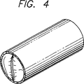
図4は、本発明にしたがって治療した後の図2の静脈部分の部分横断面図である。
図5は、本発明にしたがって別の治療部位まで送られた図3に示すカテーテル及び静脈の部分横断面図である。
図6は、本発明にしたがって逆行性の方向に静脈治療部位まで送られ、側方に偏向されたカテーテルの部分横断面図である。
図7は、球根状先端部及び本発明にしたがって拡張静脈を治療するリング電極を備えたカテーテルの実施形態の部分横断面図である。
図8は、作業端のところの面一をなす先端部及び本発明にしたがって拡張静脈を治療するリング電極を備えたカテーテルの実施形態の部分横断面図である。
図9は、本発明にしたがって拡張静脈を治療するキャップ電極を備えたカテーテルの実施形態の部分横断面図である。
図10は、キャップ電極及び治療されるべき静脈内における電極の配置状態を心出しするためのバルーンを備えたカテーテルの別の実施形態の部分横断面図である。
図11a、図11b及び図11cは、本発明にしたがってカテーテルの電極と静脈壁を互いに並置させるよう横方向に偏向する曲げ自在な先端部を備えたカテーテルの別の実施形態の部分横断面図である。
図12a及び図12bは、カテーテルの一方の側部にバルーン、カテーテルの作業端の他方の側部に長手方向電極を備えていて、本発明にしたがって電極を移動させてこれを静脈壁に並置接触させるカテーテルの別の実施形態のそれぞれ部分横断面側面図、部分横断面平面図である。
図13は、本発明にしたがってカテーテルの作業端の有効直径を増大させるために外方へ偏向する曲げることができる電極を備えたカテーテルの別の実施形態を示す図である。
図14は、本発明にしたがってカテーテルの作業端の有効直径を増大させるために外方へ偏向する曲げることができる電極及びバルーンを備えたカテーテルの別の実施形態を示す図である。
図15aは、本発明にしたがって等間隔を置いて設けられた4つの電極を備えた図14に示すカテーテルの実施形態の横断面図である。
図15bは、本発明にしたがって2対をなす電極を形成するよう優先的に間隔を置いて設けられた4つの電極を備えた図14に示すカテーテルの実施形態の横断面図である。
図16は、等間隔を置いて設けられた4つの電極を備えていて、本発明にしたがって逆行性の方向で静脈治療部位まで送られたカテーテルの別の実施形態の部分横断面図である。
図17は、本発明にしたがってバルーンの表面に等間隔を置いて設けられた4つの電極を備えるオーバーワイヤ型のカテーテルの実施形態の部分横断面図である。
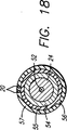
図18は、本発明による図17のオーバーワイヤ型カテーテルの18−18線における横断面図である。
図19は、本発明にしたがってバルーン部分内に設けられた電極を備えるカテーテルの別の実施形態の部分横断面図である。
図20は、加熱治療系統のブロック図と結合された本発明による弓反り自在な電極を備えたカテーテルの実施形態の側面図である。
図21は、本発明にしたがってカテーテルの作業端の有効直径を増大させるために外方へ偏向する電極を備えた図20に示すカテーテルの作業端の部分側面図である。
図22は、図21に示すカテーテル用電極の22−22線における横断面図である。
図23は、図20の23−23線における横断面図であり、本発明による4つの等間隔を置いて設けられた電極を備えるカテーテルを示す図である。
図24は、図23に示すカテーテルの別の実施形態の横断面図であり、この実施形態が、本発明による2対の電極を形成するよう優先的に間隔を置いて設けられた4つの電極を備えている状態の図である。
図25は、図23に示すカテーテルの別の実施形態の横断面図であり、この実施形態が、本発明による2対の対向した電極を備える状態の図である。
図26は、図20の26−26線におけるカテーテルの横断面図である。
図27は、バルーン及び本発明による電極を備えた曲げることができる部材を備えたカテーテルの別の実施形態の作業端の部分側面図である。
図28は、図26の28−28線における横断面図である。
図29は、本発明にしたがって治療される痔核領域の静脈系の部分横断面図で、ある。
図30a、図30b、図30c及び図30dは、本発明にしたがって拡張静脈内の静脈治療部位を治療するカテーテルの実施形態の側面図である。
図31は、本発明にしたがって治療される静脈のある食道領域の解剖学的領域の部分側面図である。
図32a、図32b及び図32cは、本発明による治療を行うために構成されると共に拡張静脈内の静脈治療部位まで送られるカテーテルの実施形態の側面図である。
実施の形態の詳細な説明
例示の図面に示すように、本発明は、少なくとも1つの電極を静脈治療部位に送るカテーテルを用いる静脈の静脈内式治療に関する。本明細書では、以下に説明する本発明の種々の実施形態において、同一の符号は同一の要素を示している。加うるに、もし特段の指定がなければ、「作業端」は、患者内の治療部位に向かう方向を指し、「連結端」という用語は患者体内の治療部位から遠ざかる方向を指すものとする。本発明を下肢の静脈系の治療と関連して説明する。しかしながら、本発明はこれに限定されず、身体の他の領域の静脈を治療するために管腔内手法的に用いることができ、例えば痔核、食道静脈瘤、陰茎の静脈ドレナージ不能症(インポテンス)に用いることができる。さらに、本発明を電極からのRFエネルギを用いるものとして説明するが、他の形態のエネルギ、例えばマイクロ波、超音波、直流電流、循環加熱流体、放射光、及びレーザを用いることができ、さらに、抵抗コイル又はキュリー点素子から生じた熱エネルギを同様に用いることができることは理解されるべきである。
機能不全弁を有する下肢の拡張静脈の部分横断面図が図1に示されている。これら静脈は、筋肉組織内にあることが多い。静脈は、二尖弁を有し、正常で完全な状態の弁では、各弁尖は、血液の嚢又はリザーバを形成し、これは圧力下では弁尖の自由端を互いに押しつけて血液の逆行性の流れを防止すると共に心臓への順行性の流れだけを可能にする。静脈の上向き矢印は、心臓に戻る血液の順行性の流れを示している。静脈弁は、血液が静脈管腔を通って前方に押し出されて心臓に戻る時に逆行性の流れを防止する。
機能不全弁が逆行性の流れを受けると弁は閉じることができないので弁尖は正しくシールすることができず、血液の逆行性の流れが生じる場合がある。機能不全弁は、拡張血管の伸張に原因する場合がある。弁が働かないと、増大した圧力が下方の静脈及び静脈の下方の弁に及ぼされ、それによりこれら下方の弁の機能不全症状を悪化させる。図1の2−2線における拡張静脈の横断面斜視図が図2に示されている。弁尖は、静脈壁が弁尖のところで薄くなって引き伸ばされることにより、交連のところで幾分引き離される場合がある。
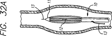
本発明の侵襲が最小限度の静脈機能不全治療方法は、カテーテル10を用いて電極12を静脈治療部位に送ることによって達成できる。その目的は、静脈の弁完全閉鎖機能を回復することにある。電極12を静脈治療部位に送るためのカテーテル10の一実施形態が図3に示されている。電極12は、カテーテル10の作業端11に位置した2つのRFリング電極14,16であるのがよい。カテーテル10のこの実施形態及び他の実施形態を以下に詳細に説明する。さらに、静脈の機能又は弁の完全閉鎖を回復するための機能不全状態の静脈の修復又は再建にあたり、静脈組織を加熱して収縮させるために輻射エネルギ、熱エネルギ又は他の形態のエネルギを用いる任意適当な装置と共に用いるよう計画されている。特に、脚内の機能不全状態且つ拡張蛇行状態の静脈の治療に関して説明するが、本発明の方法は身体の他の領域中の静脈の治療にも適している。
下肢の静脈を治療する際、患者は一般に、足をだらりと下げた状態で処置台の上に載る。その目的は、脚の静脈に血液を充満させるためである。患者の脚に対して防腐液で準備を施す。周知のセルディンガー(Seldinger)法を用いて経皮導入器を静脈中に挿入して伏在静脈系又は深在静脈系に接近する。変形例として、静脈切開術を用いて治療されるべき静脈に接近してもよい。機能不全弁の修復のための手順は、資格のある医師が透視検査による観察又は超音波による観察を用い又は用いず、或いは直接的な視覚化のもとで行うことができる。さらに、医師は、浅在静脈系の治療の際、手術中に治療部位を触診してカテーテルがどこにあるか及び治療部位がどこであるかを判定することができる。
カテーテル10を、導入器を介して挿入した後、静脈内に通して静脈治療部位まで前進させるのが良い。変形例として、カテーテルのためのガイドワイヤを静脈中に挿入してもよい。ワイヤを静脈治療部位、例えば、治療されるべき最も近い位置にある機能不全状態の静脈部位のレベルまで順行方向に進める。次に、カテーテルをワイヤ上でこれに沿って挿入し、脚の上方に静脈を通って、逆行性の流れが存在する静脈部分のレベルまで送る。いずれの場合においても、カテーテル10は電極12を静脈治療部位に送る。透視検査、X線、超音波又はこれらと類似した映像化技術を用いてカテーテルの特定の配置方向を定めて静脈内の位置を確認するのがよい。X線造影剤をカテーテル内又はその周りに注入すると、修復されるべき機能不全状態の静脈部分がどこにあるかが分かるようにすることができる。
順行性手法では、カテーテルを静脈弁に押し込んで電極が治療されるべき機能不全状態の静脈部分の弁を横切って位置するようにするのがよい。カテーテル10は、図3に示すように、静脈弁を通って順行方向に移動し、電極12が治療されるべき静脈の拡張部分の近くに位置するよう位置決めされる。電極を機能不全静脈弁を通過して延びるように位置決めするのがよい。カテーテル10の電極12を静脈治療部位に位置決めすると、RF発生器を作動させて、好ましくは、250kHz〜350MHzの範囲の選択された周波数で適当なRFエネルギを出す。適当な一周波数は、40MHzである。適用された周波数の選択のための一判断基準は、静脈内の凝血を最小限にすることにある。別の判断基準は、組織内の加熱効果の広がり及び深さを制御することにある。加熱の程度又は組織内への侵入深さは一般に、周波数が低くなればなるほど増加し、周波数が高くなればなるほど減少する。マイクロプロセッサを用いると、上述の判断基準に応じて互いに異なる静脈を治療するための周波数を選択することができる。例えば、マイクロプロセッサは、メモリに記憶されていて、凝血を最小限にすると共に加熱効果の広がり又は深さを制御する判断基準に応じて種々の静脈及び静脈直径を取り扱うための特定の周波数を関連づける表を有することができる。電極から放出されたエネルギを静脈組織内で熱に変換する。静脈組織の温度が上昇すると、静脈組織は収縮を始める。収縮は、1つには静脈中の膠原繊維の脱水及び構造変化によるものである。膠原又はコラーゲンはこの過程で圧縮されるようになるが、膠原は依然としてある程度の弾力性を保持する。RFエネルギを拡張静脈及び静脈弁の位置の近傍に及ぼすと、静脈の収縮により、静脈弁の正しい機能発揮を妨害する拡張を減少させることによって弁の完全閉鎖機能が回復される場合がある。
電極12近傍のカテーテル10の作業端11は物理的に収縮量を制限する。作業端11は好ましくは、静脈の完全な結紮を防止するのに十分な大きさになっており又は拡大されている。他の手段、例えば膨張可能なバルーンを用いても静脈中の収縮量を機械的に制限し又は制御することができる。
電極12から適用されたRFエネルギが周囲の静脈組織を加熱して収縮を引き起こした後、静脈拡張度は減少する。RFエネルギは、静脈の十分な収縮が生じて弁の近くの静脈の拡張が無くなって静脈の機能又は弁の完全閉鎖機能が回復されると、もはや適用しない。十分な収縮が生じたかどうかは、透視検査、外部超音波走査、脈管内超音波走査、インピーダンスモニタリング、温度モニタリング、血管鏡を用いる直接視診又は任意他の適当な方法を用いて検知できる。例えば、カテーテル10を、X線造影剤を送って収縮過程中の静脈の治療部位に対するカテーテルの関係及び静脈の状態を評価するために透視検査による目視を可能にするよう構成するのがよい。透視検査に代わる手段として、種々の角度からの別個の超音波信号を用いる外部超音波技術、例えばB走査法(B-scanning)又は脈管内超音波技術を用いて治療部位における一層多次元的な静脈収縮観察図を得てもよく、これにより静脈中の不均一な収縮の検出可能性が向上する。また、血管鏡を用いると、静脈の収縮の程度及び度合を直接視覚化して判定することができる。
治療後、静脈弁の交連及び弁尖を分離又は脱病状を殆ど生じずに互いに近接することが必要であり、それにより、弁の完全閉鎖状態の回復が分かる。RFエネルギを用いて治療した後の静脈弁の横断面図が図4に示されている。弁の完全閉鎖機能が得られたかどうかは、造影剤注入又はドップラープローブ測定法により判定できる。
特定の治療条件に応じて相当な度合の収縮を非常に迅速に達成することができる。収縮はかなり早い速度で生じうるので、RFエネルギを好ましくは低出力レベルで適用する。上述したように、RFエネルギの周波数は、凝血を最小限にすると共に治療部位における加熱効果の広がりを制御するよう選択される。治療部位の性質、例えば温度をRFエネルギのためのフィードバック制御を可能にするようモニターするのがよく、その目的は、凝血を最小限にすることにある。他の技術、例えばインピーダンスモニタリング及び超音波パルスエコー法を、十分な静脈の収縮が検出されると、静脈部分に対する電極からのRFエネルギの適用を止めて静脈の過熱又は焼灼を避けるようにする自動化装置に用いてもよい。また、RFエネルギのための自動フィードバック制御装置でこれらの値をモニターすることにより、加熱効果の広がり(深さを含む)を制御することができる。すべての場合において、RFエネルギの適用は、静脈弁の完全閉鎖機能を回復させてこれを維持するのに十分静脈組織を収縮させるよう制御される。
図3に示す静脈部分の治療後、カテーテル10を図5に示すように、機能不全状態にある次の下方に位置する静脈弁に移動させる。電極12を図3と関連して上述したように静脈弁を横切って配置するのがよい。しかしながら、別な場所にも電極12を用いてもよい。例えば、図5に示すように、電極12を静脈弁の弁尖の直ぐ下又はその逆行したところに配置する。RFエネルギの適用時に弁の下に電極を配置することは、静脈弁の薄い弁尖に及ぼされる局所的なRFによる加熱の効果を最小限にするのに有利であり、それと同時に静脈の機能又は弁の完全閉鎖機能を回復するよう静脈の収縮を達成することができる。
カテーテルを流体送出し内腔を有するものとして設計した場合、冷却用流体を治療されている静脈のRFによる加熱中、送出し内腔を通って血液の流れまで送ることができる。送りだされた冷却用流体は、血液に対する加熱の影響を最小限に抑え、凝血が生じる程度まで血液を加熱する恐れを小さくする。流体を、作業端及び電極近傍のカテーテルの側部に沿って形成された穴を通って送るのがよい。
本発明の方法を上記において弁の完全閉鎖機能を回復するものとして説明したが、本発明はこれに限定されるわけではない。拡張静脈の隣接した軸方向部分を治療するには、例えこれが広範囲にわたっていてもRFエネルギを拡張静脈部分に沿って適用することによって治療可能である。拡張静脈を、本発明によるRFエネルギの制御された適用のもとで収縮させて正常な直径の状態に減少させる。かかる治療は、拡張蛇行静脈の美容形成的治療において用いることができる。さらに、治療中、静脈が厚くなることがあり、これは拡張蛇行静脈及び静脈機能不全の再発の恐れを減少させることができる。
カテーテル10を、必要な程度に多くの静脈部分及び弁を治療するよう再位置決めすることができる。すべての所望の静脈部分を修復して弁の機能を完全にするまでRFエネルギを修復されるべき各静脈部分に適用する。多数の機能不全弁及び機能不全状態又は拡張した静脈部分を侵襲が最小限に抑えられた単一の手順で治療修復することができる。所望ならば、治療されるべきところがどこであれ深在静脈系又は浅在静脈系のいずれかに接近できるようにするため、第2の導入器を患者の肢内へ挿入することができる。次に、カテーテルを用いて他の静脈系中の機能不全状態の静脈部分を治療することができる。
図3及び図5に示すような順行方式に代えて、カテーテルは、逆行性の方向から電極を静脈治療部位に送ることができる。カテーテル10を皮膚内へ導入して逆行性の方向で静脈中へ導入する。カテーテル10は治療されるべき機能不全状態の静脈部分の上でこれに隣接した静脈に侵入することができる。電極を、静脈弁の弁尖との接触が透視検査、超音波法又は他の検出方法によって観察されるまで前進させる。次に、カテーテルを僅かに引き戻して静脈の拡張部分の治療を行うことができるようにする。電極を動作させてRFエネルギを静脈組織に送り出し、静脈を収縮させる。静脈の収縮は、結紮を防止して静脈の機能を続行させることができるよう制限するのがよい。カテーテル又は伸長自在な部材の外径を制御すると、静脈の収縮の大きさを制限することができる。
RFエネルギを一層特定的に静脈弁の分離状態にある交連に適用することは、静脈機能及び弁完全閉鎖機能を回復するうえで効果がある。カテーテル10を、電極を静脈内に位置決めして電極を修復されるべき静脈部分に並置させるよう構成するのがよい。カテーテルは、電極の正しい配置が得られるように偏向させ、トルクを与え、或いは又は他の手段で動かすことができる。変形例として、恒久的な曲げ部をカテーテルの作業端近傍に形成してもよく、次にこれを次に回したり捩じって所望の並置状態を達成することができる。カテーテルの作業端を操作することにより、所望ならば電極を静脈壁の一方の側に近接して配置したところで治療中の静脈壁に沿って優先的又は選択的に加熱を行うことができる。
図6に示すような偏向したカテーテルの電極12を、逆行方式から交連の近傍の静脈壁に密接並置関係で配置することができる。また、カテーテルを操作して電極を静脈弁の交連に密接して並置状態で配置して交連近傍の局部的な収縮を引き起こすと、静脈の拡張部から交連の任意の分離状態を矯正すると共に静脈の機能及び弁の完全閉鎖機能を回復させることができる。弁の交連の一端を治療した後、次に、カテーテルを移動させて弁の反対側の交連近傍に電極を配置するのがよい。かくして、RFエネルギを静脈壁の一方の側に選択的に適用した後、カテーテルを180°回してエネルギを静脈壁の他方の側に適用して静脈の機能の回復を促進させるのがよい。変形例として、図12に示すような非対称のバルーン又は他のかかる位置決め装置を用いると、電極を治療されるべき静脈部分にあてて並置させることができる。バルーンを収縮させて次に膨張させるとカテーテルの移動及び再位置決めを容易にすることができる。
静脈の一部分の治療後、カテーテルを治療されるべき静脈の次の部分のレベルまで移動させるのがよい。次に、同一の手順を繰り返し行って静脈の修復を次々に行う。治療を数回繰り返して、ついには十分な収縮を達成して静脈の機能及び弁の完全閉鎖機能を回復すると共に静脈が開存性を維持するようにする。機能不全状態の静脈部分の治療を完了すると、電極を収容しているカテーテルを静脈から取り出す。
図3及び図5に示すように周囲の静脈組織の局所的加熱及び上述の静脈の収縮を引き起こす電極12を作業端11に備えたカテーテル10の実施形態が図7に一層詳細に示されている。電極12は、2つのリング電極14,16を有している。端部のリング電極14は能動側電極、リング電極16は戻り電極としてそれぞれ作用するのがよく、或いは、リング電極14は戻り電極、リング電極16は能動側電極としてそれぞれ作用してもよい。端部リング電極14は好ましくは、カテーテルの作業端の先端から遠ざかって位置し、カテーテルの作業端は、プラスチック又は他の幾つかの非導電性材料で作るのがよい。リング電極14,16によって作られるRFの場又は作用範囲は、カテーテルの端を越えて広がってはならない。カテーテルの作業端の不活性の非導電性先端は、RF場の広がり及び形成を制限することによってカテーテルの端部を越える収縮を防止するのに役立つ。この非導電性先端は、収縮制限マンドレルとしての役目を果たし、それにより、カテーテル先端よりも小さな直径への静脈の収縮を防止し、この非導電性先端は電極14〜25mm越えるのがよい。両方の電極14,16は好ましくはステンレス鋼製である。絶縁材料18が、端部電極とリング電極との間に設けられている。カテーテル10及び電極12は、透視検査、X線、超音波又は他の映像化技術のもとで視覚化を可能にする材料で作られるべきである。例えば、カテーテル10は、X線造影剤を送り出して透視検査によって視覚化可能なように構成されるのがよい。静脈中に注入された造影剤を用いると、静脈の状態及び静脈の治療部位に対するカテーテルの関係を、収縮過程中の静脈造影法によって評価することができる。
カテーテル10は、好ましくはTFEテフロンから作られた絶縁層22によって包囲されている撚り中央導体20を有している。銀被覆銅ブレード24が、絶縁中央導体を包囲していて、カテーテルのシャフトに可撓性且つトルクをかけることができる特性を付与している。外装又はシース26が銅ブレード又は編組24を被覆している。外装26は、低摩擦係数の電気的に抵抗性の生体適合性材料、例えばテフロンで作られている。中央導体20は、電源64、例えばRF発生器に接続されていて、RFエネルギを電極12に提供している。
電極12をリング電極として説明したが、他の電極形態及び構造を用いてもよい。例えば、等距離間隔をおいた長手方向電極を用いて静脈の全方向性及び周囲方向の収縮を可能にすると共に静脈の長手方向の収縮を最小限に抑える。電極は、電極の周りに円周方向にRF場を形成する。
双極性構成について説明したが、単極形構成も使用できることは理解されるべきである。単極形構成では、内側の電極、例えばメッシュ又はワイヤ電極は、患者体内の腔内へ挿入される。内側電極よりも表面積の大きい外側電極が、治療部位の近くで患者の身体の外面上に配置される。例えば、外部金属プレートが、内側電極によって治療されるべき領域上で皮膚の上に置かれる。電極は、患者の体内に電界を作るRF発生器に接続されている。内側電極の表面積は外側電極の表面性よりも非常に小さいので、電界密度は、内側電極の周りにでは一層高い。電界は、2つの電極の間で内側電極近傍の領域において最も高い密度に達する。内側電極の周りの電界密度の増加により、内側電極を包囲している組織の局部的な加熱が可能となる。加熱の度合は、加熱されている組織のインピーダンス及び誘電率のような要因で決まる。
端部リング電極14及びリング電極16は好ましくは、例えばインピーダンスのような値を測定するためのセンサ60相互間に配置される。インピーダンスの測定の際、以下に一層詳細に説明するように、電極相互間の領域は、最も適切なデータを提供する場合が多い。センサ60を用いると温度及び超音波信号を含む他の値を測定することができることは理解されるべきである。さらに、カテーテル10上へのセンサ60の位置決めは、測定中の値に応じて変化する場合がある。例えば、温度を測定する場合、センサを電極上に又はその直ぐ隣に配置することが望ましい。温度センサは、電極の周りの組織の温度を検出する。パルス化超音波のエコー信号を測定する際、センサを電極相互間に又はカテーテルの先端に配置するのがよい。パルス上エコー超音波信号を測定する場合、カテーテルを好ましくは回転させてカテーテル及びセンサの周囲の環境の像を解像する。
センサ60は、静脈収縮度を判定するのに用いることができるパラメータを測定する。例えば、センサ60は、電極14とリング電極16との間の接触状態にある静脈組織のインピーダンスを測定する検出用電極であるのがよい。一定のRF電流が能動端部電極14から戻りリング電極16に放出される。また、インピーダンスを電極14,16相互間で直接測定するのがよい。電極前後の電圧は、検出用電極によって測定され、電極相互間の体積のインピーダンスが検出される。測定された電圧は、電極相互間のインピーダンスZに比例し、ここでZ=V/I、電流Iは一定である。インピーダンスは、静脈の直径の関数として変化する。というのは、静脈直径が増加すると血液が少なくなると共にコンダクタンスが小さくなるからである。収縮により体積が減少すると、電極相互間の導電体積の量が減少し、インピーダンスの増加によりこれに対応して測定電圧が増加する。この技術により、静脈収縮の測定値を相対的に得ることができる。検出用電極からの信号をモニター又はマイクロプロセッサ62に入力するのがよく、マイクロプロセッサ62は、制御信号をRF発生器64に送ることができる。その目的は、測定した相対的インピーダンスにしたがってRFエネルギを電極に適用するのを制御することにある。変形例として、医師の手動制御を可能にするためにモニター上に視覚的に表示してもよい。
変形例として、センサ60はサーミスタのような温度センサであってもよい。温度センサを、電極近傍のカテーテルの作業端上に設けて電極及び治療中の静脈部分の周囲の温度をモニターしてもよい。モニターした温度が静脈組織が収縮を開始する特定の温度に達するか、或いはこれを越えたとき、電極からのRFエネルギの適用を止めるのがよい。モニターした温度にしたがう電極へのRFエネルギの適用を制御するために温度センサからの信号をマイクロプロセッサ62に入力するのがよい。
検出用電極又はサーミスタに代わる手段として、他の実施形態としては、センサ30としてパルス化超音波を放出する超音波圧電素子が用いられる。圧電素子は、パルス−エコー法で動作してカテーテルのシャフトからの静脈壁までの距離を測定する。この場合も、パルス−エコーを表わす信号をマイクロプロセッサ62又は手動制御を可能にするモニターに入力するのがよく、RFエネルギの適用は、カテーテルと静脈壁との間でコンピュータ処理された距離にしたがって制御される。
図7に示すようなカテーテル10の作業端11は、カテーテルを静脈内で操作するときに、思いがけない損傷を最小限に抑える無外傷性先端部となるよう丸くされている。カテーテル10の作業端11は、局部的な静脈の収縮量を制限する拡大された寸法を有するのがよい。拡大された無外傷性先端部は、作業端11に球根状の形を用いて達成できる。サイズの異なる作業端11及び電極12を、カテーテル10とは別個に製造して後でカテーテル10のシャフトと組み合わせるのがよく、したがって単一のカテーテルシャフトを種々の直径の作業端と共に使用することができるようになる。この場合、特定のサイズ又は形状を有する作業端を、治療される静脈のタイプに応じてカテーテル10と共に使用するのがよい。例えば、或る大静脈は、直径が7〜8mmであり、他の静脈の直径は2〜3.5mmに過ぎない。変形例として、作業端11及びリング電極14,16を図8に示すようにカテーテルのシャフトと面一をなし、即ちこれと同一平面上に位置するようにしてもよい。他の方法、例えば透視検査による収縮量のモニタリングを用いて、収縮量の判定及び制御を行ってもよい。他の点に関しては、図8のカテーテルの構成は、上述したように図7の構成と同一である。
カテーテル10の別の実施形態は、端部電極14を有し、この端部電極14は、カテーテル10の作業端11の先端に形成されたキャップ電極である。図9に示すように、端部電極14は好ましくはステンレス鋼製である。端部電極14は能動側電極として働き、リング電極16は戻り電極として働く。カテーテル10のキャップ電極14は、カテーテルを静脈中に通して操作するとき、周囲の静脈組織に対する損傷を最小限に抑えるよう無外傷性先端部となるよう丸くされている。電極14,16の外径は一例では7French又は約2.3mmである。変形例として、カテーテル10のキャップ電極及び作業端11は、カテーテルの残部から見て拡大された寸法を有していてもよい。例示の図9に示すような電極及び作業端は、カテーテルの残部と実質的に面一をなしている。ブレード外装26は、カテーテルの銀被覆銅ブレード24を覆っていて、外装はリング電極16の外周部と面一をなしている。絶縁管18が、端部電極とリング電極との間に設けられている。カテーテルの作業端では、はんだ充填物28が、中央導体20と端部電極14との間に形成されている。中央導体20は、絶縁材22によってリング電極16から絶縁されている。図9の端部キャップ電極は、カテーテルの先端に隣接した静脈の収縮を制限せず、したがって所望ならば静脈を完全に収縮させることができる。
別の実施形態では、ブレード付きシャフト上に同軸状に装着された膨張可能なバルーン40が、静脈管腔内でカテーテル10及び電極14,16を心出しすることができる。その目的は、静脈管腔の部分の不均一な加熱をもたらす場合のある意図しない電極と静脈管腔との接触を回避することにある。図10に示すように、バルーン40は、カテーテルの連結端に近接して位置している電極16に隣接して設けられている。バルーン40は好ましくは膨張可能であって可撓性があり、ラテックスのような弾性材料で作られており、これは中程度の直径をもたらすことができる。バルーンを食塩水又は他の導電性溶液で膨らますのが良い。
図6と関連して説明したように、治療部位における電極と静脈組織との選択的な並置状態を維持することが望ましい場合がある。図11a,図11b及び図11cに示すカテーテル10の実施形態は、シャフト偏向ワイヤ29によって偏向させることができる。カテーテルは、銀被覆銅シールド24及び絶縁外装26を有している。電極12は、上述したように4つの周囲方向に間隔をおいた長手方向電極であるのがよい。図11a及び図11cは、4つの長手方向電極のうち2つだけを示している。カテーテル10はさらに、カテーテルの作業端を除きカテーテルのシャフトの周りに形成された補剛ジャケット25をさらに有している。中央の中空ワイヤ内腔27が、カテーテルの長さを貫通して延びている。シャフト偏向ワイヤ29は、その作業端近傍に形成された剛性の曲げ部を有しており、カテーテルのワイヤ内腔27内に押し込まれる。カテーテルの作業端の先端まで進む剛性曲げ部の次に位置するワイヤ29の端部は好ましくは可撓性があってしなやかである。補剛ジャケット25は、シャフト偏向ワイヤがカテーテルの作業端に達するまで、カテーテルのシャフトがシャフト偏向ワイヤ29によって偏向されるのを防止する。シャフト偏向ワイヤ29内の曲げ部は、カテーテルの作業端11を一方の側に移動させる。次に、電極12を治療されるべき特定の静脈組織と並置関係になるよう選択的に配置することができる。また、造影剤を内腔27を通して治療部位に送るのがよい。さらに、冷却用溶液又は流体を、内腔27を通して治療部位に送ることができる。内腔のための側部ポート30を、造影剤及び冷却用流体を送り出すために電極12の近傍で作業端に形成するのがよい。変形例として、内腔27をカテーテルの作業端の先端のところで閉じてもよい。その目的は、造影剤又は冷却用溶液の注入を側部ポート30から行うことができるようにすることにある。内腔27を先端のところで閉じることにより、偏向ワイヤ29を、カテーテルの先に延びる一層堅いワイヤについて心配することなく、一層剛性に製造することができる。
別の実施形態は、カテーテルの作業端11のところの電極12を一方の側に偏向させるために非対称のバルーン40を用いている。電極12は、カテーテルの一方の側に設けられた一対の長手方向電極である。図12a及び図12bに示すように、バルーン40はカテーテルの反対側に設けられている。バルーン40を膨らますと、長手方向電極を収容している作業端11の反対側の側部は、治療されるべき静脈組織と並置する状態に移動する。拡張静脈部分の治療後、バルーン40を萎ませて、カテーテルを脈管系から取り出す。作業端を偏向させる他の装置を使用できることは注目されるべきである。例えば、非対称のバルーンの機能と同一の機能を果たすため、曲げることができる操作ワイヤをカテーテルの一方の側に用いてもよい。カテーテルはさらに、ジャケット26、ブレード24及びTFE絶縁材22を有し、これは上述の実施形態の構成と同一の構成のものである。
図13に示すような別の実施形態では、カテーテル10は、4つの導電性の細長い部材の形態をしている弓反り自在な電極12を有している。弓反り自在な電極12は、カテーテルの周囲に沿って形成された長手方向電極と類似しているが、カテーテルには固定されていない。カテーテル自体は、手術のための適当なサイズの外装に嵌入できる。例えば、直径が約3mmの9French外装を用いてもよい。カテーテルの作業端11は、カテーテルの連結端のところに設けられた直径アクチュエータ33によって手動制御される可動先端部31を有している。可動先端31は、カテーテルを通って延びる中央ワイヤ(図示せず)によって直径アクチュエータ33に連結されている。直径アクチュエータ33を、カテーテルの連結端に螺着するのがよい。アクチュエータ33をカテーテルの連結端部内へ出し入れすることにより、これに対応した動きがカテーテルの作業端のところでの可動先端31に与えられる。もし可動先端31を直径アクチュエータ33によって連結端に向かって引くと、電極12は外方に弓反りになる。弓反り自在な電極12は好ましくは、拡張して静脈を最大8mmまで拡張する。可動先端31を直径アクチュエータ33によって押し出すと、弓反り自在な電極12はカテーテルのシャフトに向かって引っ込められる。電極と静脈壁との接触を常時維持することができる。
収縮度を、カテーテルと電極を組み合わせた時の有効直径によって制御できる。電極12は、カテーテルの有効直径の一部として半径方向外方に弓反りになることができ、それにより静脈壁との並置関係になる。RFエネルギを適用すると、静脈はカテーテルの有効直径まで収縮しはじめる。カテーテルの有効直径は、収縮量を制御する医師の制御のもとで減少する。有効直径が減少すると、電極は静脈組織との並置関係を維持し続ける。従前のように、静脈収縮度を、透視検査又は他の任意の適当な方法によりモニターすることができる。静脈を所望の直径まで収縮させた後、電極12からのRFエネルギの適用を止める。所望の直径は、偏向した電極12によって定まるようなカテーテルの最終有効直径であるのがよい。
電極12をバネ鋼又はニチノールで作るのがよく、したがって電極12を付勢して減少した直径のプロフィールに戻すことができるようになる。弓反り自在な長手方向電極が全長にわたって導電性である場合、絶縁材35を意図しない加熱効果を防止するために電極表面の大部分上に施すのがよい。電極の端部は特に、有効直径が減少するときに可変電界密度の発生を防止するために互いに絶縁されており、有効直径が上昇すると、これにより端部と弓反りになった中央部分との間の電界の不一致が大きくなる。絶縁材35は、ポリイミド又は他のタイプの絶縁フィルムであるのがよい。静脈壁から遠ざかって電極の後に沿って設けられた絶縁材35は、静脈中を流れる血液の加熱を一段と防止し、これはまた凝血の発生の恐れを少なくする。電極の残りの露出領域は好ましくは、並置中に静脈壁に接触する領域である。電極の露出表面積は、有効直径の周囲に沿う電極の露出部分相互間の距離を一定に保ちながら可能な限り大きくすべきである。収縮中に静脈壁に当てて並置された電極の露出表面が広ければ広いほど、電極によって生じる電界の影響を受ける静脈壁の表面積がそれだけ一層大きくなる。
図14に示すようなカテーテル10の別の実施形態は、カテーテルの作業端11に固定された一端部及び連結端に向かってカテーテルに摺動自在に連結された他端部を備えた弓反り自在な細長い部材32を有する。図14に示すカテーテルは、細長い部材を電極それ自体として作用させるのではなく、電極12を細長い部材32上に設けていることを除けば、図13に示すカテーテルと同一である。細長い部材32は好ましくは、電極12のための平らな中央領域34を有している。細長い部材32を偏向させて外方に弓反りにしても中央領域34は実質的に平らなままである。実質的に平らな中央領域は、静脈壁との接触を一層均等にすることができる。平らな領域は、細長い部材上の電極12と静脈壁との間の接触を確実にするための大きな表面領域をもたらす。平らな領域34を細長い部材32の中央に設ける必要はないことは理解されるべきである。平らな領域は、静脈壁に接触する最初の領域であるよう設けるべきである。図14に示す細長い部材32は、カテーテルのシャフトの外部に沿って形成された摺動スリーブ36に連結されている。電極12を半径方向外方及び内方に移動させると、摺動自在なスリーブ36は作業端に近付いたりこれから遠ざかったりする。
バルーン40を、カテーテルのシャフトと細長い部材32との間に設けるのがよい。摺動スリーブを手動で操作することはこの実施形態では不要であり、スリーブはカテーテルの相当な長さにわたって移動する必要はない。バルーン40を膨らませるとこれは細長い部材32に接触する。バルーン40を一段と膨張させると、電極12は、細長い部材が膨張中のバルーン40によって偏向されて弓反りになると、半径方向外方に移動する。特に細長い部材が電極を収容している場合又は細長い部材それ自体が導電性であって電極として働く場合、好ましくはバルーンを非導電性流体で膨張させる。電極の適性な直径が達成されると、バルーンの膨張が止まり、RFエネルギの適用が始まる。バルーン40は静脈治療部位上のより広い表面積を覆い、静脈の収縮量を制御しながら静脈壁に対する正しい電極の配置を確実にする。バルーンの形状及び直径をより正確に制御することは、弓反り自在な部材を用いることによって可能となる。RFエネルギを適用すると、静脈は収縮を開始する。カテーテルの有効直径は、収縮量を制御する医師の制御のもとで小さくなる。有効直径が減少しても、電極は静脈組織との並置関係を維持し続ける。電極12からのRFエネルギの適用は、静脈を所望の直径(これはバルーン40及び偏向した細長い部材32の直径によって定まる最終有効直径である)に収縮させた後停止される。次に、バルーン40を最小のプロフィールまで萎ませる。細長い部材32は好ましくは、バネ鋼又はニトロールで作られ、したがって細長い部材32はバルーンを萎ませると減少した直径プロフィールまで戻るように付勢される。
15−15線における図14の電極12の横断面図が、図15aに示されている。4電極形構成では、好ましい実施形態では、電極12をカテーテルの周囲に沿って等間隔に配置する。各電極の極性は好ましくは直ぐ隣の電極の極性と反対である。かくして、一定のRF場を交互に位置した電極によってカテーテルの周囲に沿って形成する。図15bに示すような別の実施形態では、隣合う電極が互いに一層近づく場合、互いに逆の極性の2つの有効な対をなす能動側電極をカテーテルの周囲に沿って形成する。RF場がカテーテルの全周に沿って依然として形成されている間、RF場は、互いに逆の極性の最も近い隣合う電極相互間で最も強い。静脈の収縮は、RF場が最も強いところに集中するであろう。
図14と関連して説明した実施形態の変形例では、外側スリーブ36はカテーテルの長さに沿って下方に延びることができ、それによりオペレータ又は医師はRFエネルギの適用中有効電極直径を機械的に制御することができ、したがって別個のバルーン40は不要である。摺動自在なスリーブをカテーテルの作業端11に近付けることにより、電極は偏向して半径方向外方へ弓反りになって増大した直径となる。外側スリーブ36を予め定められた距離移動させると電極が既知の直径まで外方へ弓反りになることができるようになる。また、電極を外方へ弓反りにすると、電極は治療されるべき静脈組織と並置関係におかれる。スリーブ36をカテーテルの連結端に向かって移動させると、電極が引き戻され、挿入又は静脈からの取り出し前にカテーテルに当たってひらべったくなる。スリーブを移動させることにより電極の配備時の直径を制御し、種々の直径を有する静脈管腔の適切な治療を行うと共に様々な静脈収縮度をもたらすようにする。例えば、電極を静脈組織と接触して配置し、有効直径を機械的に減少させてRFエネルギが適用されている間、収縮量を制御することができる。
別の実施形態では、外側スリーブに代えてスリーブに取り付けられている細長い電極の端部をカテーテルの周囲に沿って設けられた長手方向スロット又はチャンネル内に摺動自在に配置する。弓反り自在な部材の端部は、これらの部材を外方へ偏向させ又は弓反りにさせるとこれらのチャンネル内の作業端に向かって摺動し、連結端に向かって引っ込んで戻り、それによりそれらのもともとの形態に戻る。
別の変形例では、好ましくはRFエネルギを単極形構成で適用する場合、電極及び細長い部材に代えて単一のワイヤメッシュ又は編組電極を用いてもよい。従前通り、バルーンはメッシュ電極を半径方向外方に延ばしてこれを静脈壁に並置させる。バルーンはまた、静脈の収縮量を制御することができる。
図13及び図14のカテーテルの有効直径を変えるための別の方法は、電極12を移動させてこれを静脈壁に直接接触させることである。電極がRFエネルギを放出すると、静脈壁は収縮して電極をカテーテルに向かって内方へ押す。静脈の収縮により、医師の積極的な制御によってではなく、直接有効直径が小さくなり、それにより有効直径に対する機械的な一定の微調整が不要となる。例えばプッシュロッド又は一定直径のバルーンのような器具を用いて特定の有効直径での電極のそれ以上の半径方向の収縮を防止、それにより静脈の収縮量を制御し制限する。これは、電極を静脈組織と並置した関係に維持するという利点を有し、したがって周囲の血液以上に組織が加熱され、この場合医師はRFエネルギを適用しながらカテーテルの有効直径を常時調節することが必要とされない。
制御自在に膨張可能な又は伸張可能な他の装置を用いても、所望サイズへの静脈の収縮を制限できる。例えば、マンドレルをカテーテルの側部を通って前進させて静脈部分の収縮のための直径の限度を定めてもよい。別法として、弓反り自在な導電性偏向ワイヤをカテーテルの一方の側部に設けて静脈壁との並置関係を達成してもよい。さらに、図7に示す非膨張性カテーテルシャフト及び電極でも、これを用いて手術中に静脈の収縮量を制限することができる。静脈は単にカテーテルの一定直径まで収縮するであろう。
並置関係を維持するために別の方法をカテーテルに用いることができる。例えば、圧力カフを用いて、脚に外部圧力を及ぼして治療領域を圧迫し、静脈壁が電極に接触するようにしてもよい。電極と静脈組織の並置関係は、外部圧力を及ぼすことによって維持される。かかる外部圧迫法は、浅在静脈の治療の際に用いることができる。上述の機械的な方法とは別の方法を用いても静脈収縮の大きさを制御することができる。かかる非機械的方法として、静脈RF治療の時間及び温度を制御することが挙げられる。
カテーテル10の作業端を、図11に示すような作業端近傍に曲げ部を有するよう構成してカテーテルを回転させると、静脈内に攪拌効果を生じさせて、それによりたとえ一層収縮した場合でも静脈組織の一層均一な加熱を達成することができるようにする。恒久的な曲げ部ではなくて、カテーテルを作業端近傍に制御自在な曲げ部を有するよう製造してもよい。例えば、曲げ部を形状記憶合金で作り、ワイヤシステム、トルクを加えることができるブレード又は恒久的な曲げ部をカテーテル内に設けてこれによって操作することができるようにしてもよい。
一層均一の加熱を達成するために熱伝達を制御する別の方法は、外部圧迫帯又は止血帯を用いて血流を減少させ又は静脈治療部位のところのカテーテルの周りの静脈を圧迫することである。外部圧迫又は脈管内方式で膨張させた閉塞バルーンのいずれかにより血流を減少させることにより、静脈を通る血流の影響(これは、治療部位から熱を運び去ることができる)が最小限に抑えられる。手術中の静脈組織への熱伝達の影響は血流によって少なくなり、したがって、静脈の収縮率は一層予測可能である。また、十分な圧力を外部圧迫帯によって得て、それにより静脈を電極と並置関係にすることができる。
図16に示すような別の実施形態では、閉塞性心出しバルーン40が、静脈治療部位近傍における血液の淀みを保持するのに用いられる。単一の閉塞バルーン40を静脈弁と関連して用いると、加熱されるべき或る量の血液を保持することができ、ここに電極12を静脈弁と閉塞バルーン40との間で設けることができる。2つの閉塞バルーン(図示せず)を電極の一方の端部に形成して静脈弁から離れた静脈治療部位のところに血液の淀みを作ることができる。かかる構成は、静脈弁の治療が望まれない場合、静脈弁を隔離保護する。また、閉塞バルーンを用いると、電極を静脈管腔内に心出しすることができる。
図16に示す閉塞バルーンを用いる実施形態に限定されないが、カテーテル10は、カテーテルの周囲に長手方向に配列された電極12をさらに有する。この実施形態は、図13及び図14と関連して開示した実施形態と類似しているが、この場合、電極はカテーテルに固定されていて、外方へ弓反りにはならない。この一定直径を用いる構成により、RF場をカテーテルの周囲に沿って形成することができる。かかる構成は、全方向性収縮を可能にし、静脈の長手方向の収縮を回避させることができる。長手方向電極の特定の配置及び配向状態は好ましくは図15aに示す通りである。
図17に示すようなバルーン膨張式実施形態は、カテーテル10のバルーン40の周囲に長手方向に配置された4つの長手方向電極12を有している。この実施形態は、図13及び図14と関連して開示説明した実施形態と類似していて、全方向収縮を可能にすると共に静脈の長手方向の収縮を最小限に抑えるようになっている。長手方向電極の特定の配置及び配向状態は好ましくは、図15aに示すように等距離間隔である。図17に示すようなカテーテル10は、カテーテルがガイドワイヤ内腔52を通ってガイドワイヤ42上を移動するオーバーワイヤ(over-the-wire)型である。カテーテル10は、案内ワイヤ内腔52を包囲するブレード外装24をさらに有している。ブレード管54がブレード24の周りに形成されている。バルーン40及びバルーン管55のための内腔56は、ブレード管54を包囲している。ブレード管は、膨張流体がバルーン内腔からガイドワイヤ内腔52内へ漏れるのを止める密封バリヤを形成する。カテーテルの外部は、導体リード線20を保持するリテーナ管57を有し、導体リード線20は電極12をRF発生器に接続している。図17の18−18線におけるカテーテル10のシャフトの横断面が図18に示されている。
別の実施形態では、電極12は、カテーテル10のバルーン40の下に配置されている。図19に示されていて、図17及び図18に示すものと類似したこの実施形態により、静脈組織の熱伝導加熱が可能となる。図19に示すカテーテル10は、カテーテルが先に導入されたガイドワイヤ42上を移動するオーバーワイヤ型のものである。バルーンを膨らませ、これが膨張して静脈組織に接触する。上述のように、膨らませたバルーン40を用いると、静脈の収縮の大きさを膨らませたバルーン40の外径に制御又は制限することができる。有効直径は、バルーン40の選択的な膨張と収縮によって制御できる。バルーン40の膨張剤は好ましくは導電性流体、例えば生理食塩水溶液であり、したがって相当多量のRFエネルギが依然として周囲の静脈組織に伝えられることになろう。しかしながら、膨張剤は、RFエネルギのある程度の量を吸収することができ、これは熱に変換されることになる。RFエネルギのこの拡散は、静脈の収縮を一段と制御することができる。変形例として、従来型ヒーターコイル又はキュリー点素子を電極12に代えて用いてもよい。その目的は、膨張剤を直接加熱し、それにより熱を熱伝導により静脈組織に伝える。
周囲の静脈組織の局部的な加熱及び静脈の収縮を行う作業端11に電極12が設けられたカテーテル10の別の実施形態が図20に示されている。カテーテル10は、外方へ弓反りになることができる4つの導電性の細長い部材の形態の電極12を有している。弓反り自在な電極は、カテーテルの周囲に沿って形成されているが、カテーテルには固定されていない。カテーテルそれ自体は、手術のための適当なサイズの外装に嵌入している。例えば、直径が2.3mmの7French外装を用いるのがよい。外装は、低摩擦係数の生物学的適合性のある材料で作られている。カテーテルの作業端11は、各電極の一端に取り付けられた先端部15を有し、各電極の他端部は、カテーテルシャフトの外部に沿って形成された摺動スリーブ36に連結されている。外側スリーブは、カテーテルの長さにわたって下方に延びていて、それにより医師はRFエネルギの適用中、有効電極直径を直接且つ機械的に制御できるようになっている。摺動スリーブ36を制御アクチュエータ33に応答して作業端に近付けたりこれから遠ざけると、電極12はそれぞれ半径方向外方に押圧されたり半径方向内方に押圧されたりする。先端部15は本質的に、摺動スリーブの移動中、静止したままである。スリーブ36をカテーテルの連結端に向かって戻すと、電極は引き戻され、静脈への挿入又は取り出し前にカテーテルに当たってひらべったくなる。スリーブ36をカテーテルの作業端に向かって前方に移動させると、電極は偏向して増大した直径となるよう半径方向外方に弓反りになる。電極の接触領域は、長手方向電極の互いに反対側の端部が互いに近付けられると外方へ弓反りになる。外側スリーブを予め定められた距離移動させて電極が既知の直径まで外方に弓反りになるようにするのがよい。また、電極を外方に弓反りにすることにより、電極は治療されるべき静脈組織と並置状態になる。摺動自在なスリーブを操作して電極の半径方向の弓反り状態によって定まるカテーテルの有効直径を調節することにより、静脈が収縮しているときに電極と静脈壁との接触を維持することができる。制御アクチュエータ33は、スイッチ、レバー、ネジ付き制御ノブ又は他の任意適当な機構、好ましくは摺動自在なスリーブの移動を微調整できるものである。制御アクチュエータを用いて摺動自在なスリーブを移動させることにより、電極の有効直径を制御して種々の直径を有する静脈管腔を治療すると共に様々な度合の静脈の収縮を達成することができる。
先端部15はノーズコーンの形状を有しており、変形例としてガイドワイヤ上で静脈系中の曲がり部を通るカテーテルの追従を可能にする任意の形状を有するのがよい。ノーズコーン状先端部を、低いジュロメータ硬度、例えば70ショアー硬さAを有するポリマーから作るのがよい。変形例として、ノーズコーンを、薄いポリエチレン収縮チューブの層で覆われたバネから作ってもよい。
収縮度は、カテーテルと電極を組み合わせた状態の有効直径によって制御される。電極12は、カテーテルの有効直径の一部として半径方向外方に弓反りになって静脈壁と並置関係になる。静脈組織に接触した後、有効直径は、RFエネルギが適用されている間、収縮を制御するよう機械的に減少できる。電極12は好ましくは、双極形電極として動作する。RFエネルギを電極に適用すると、RFが、弓反りになった電極によって定められるカテーテルの有効直径の周りに生じ、静脈は加熱されて収縮を始める。カテーテルの有効直径を、収縮量を制御する医師の制御のもとで減少させる。有効直径が減少すると、電極は静脈組織との並置関係を維持し続ける。静脈の収縮度は、透視検査又は任意他の適当な方法によってモニターされる。静脈を所望直径に収縮させた後、電極12からのRFエネルギの適用を止める。静脈の所望直径は、偏向した電極12によって定まるようなカテーテルの最終有効直径である。
電極12は、細長い形状を有し、ステンレス鋼、バネ鋼又はニチノールで作られていて、電極12は減少した直径のプロフィールに戻るよう付勢される。電極は、弱い静脈構造の帯環を通って送られている間、作業端のところのカテーテルの撓みを容易にする丸いワイヤである。電極の直径は好ましくは約0.005〜0.015インチ(約0.12〜0.35mm)であるが、最大約0.03インチ(約0.7mm)の場合がある。静脈壁に接触する比較的広い平らな表面を有する矩形のワイヤを含む他の形状を用いてもよい。かかる矩形のワイヤは、0.005〜0.05インチ(0.12〜1.2mm)、好ましくは0.015〜0.030インチ(0.35〜0.7mm)の範囲にわたる幅を有するのがよく、それによりカテーテルシャフトの周りに4〜8つの電極を配置することができる。
弓反り自在な長手方向電極は全長にわたって導電性であり、絶縁材35が図21及び図22に示すように電極表面の大部分上に施されている。その目的は、意図しない加熱効果を防止するためである。導電性表面の適当な部分だけが電極として働くよう露出している。加熱効果は、電極が互いに近接している場合に最も大きい。というのは、電界密度(出力密度)がこの点で最も大きいからである。電極の端部は互いに絶縁されており、それにより電極中央の周りの電界密度と比較して端部においてそれよりも大きな電界密度が生ずるのを防止するようになっている。有効直径が増加すると、もし絶縁材が設けられていなければ、端部と外方に弓反りになった中央部分との間の電界の不一致が大きくなる場合がある。絶縁材35は、ポリイミド、パリレン又は別タイプの絶縁材料であるのがよい。静脈壁から見て反対側の電極の側部及び背部に沿って設けられた絶縁材35は、静脈中を流れる血液の加熱を一段と防止し、これはまた凝血の恐れを少なくする。ワイヤの形状が矩形である場合、電極として機能的に働く露出領域は、ワイヤの一方の面だけを占める。図22に示すように、電極の周りの絶縁材35は、電極の露出面の周縁を一段と被覆することができ、それにより血流を意図しない加熱効果から一段と隔離する。
電極の露出領域は好ましくは、並置中、静脈壁に直に接触する領域である。この場合、加熱効果は静脈壁に集中する。電極の露出表面積は、有効直径の周囲に沿う電極の露出部分相互間の一定距離を維持した状態で、可能な限り大きいものであるべきである。収縮中に静脈に当てた状態で並置される電極の露出表面が広ければ広いほど、電極が発生する電界によって影響を受ける静脈壁の表面積はそれだけ一層広くなる。電極の露出領域は、静脈壁と均一な接触状態を高め、静脈の直径を制御するために実質的に平らであるのがよい。
温度を測定するためのセンサ60、例えば小型熱電対が電極12に取り付けられている。図22の横断面図に示すように、温度センサ60は、電極に設けられた穴を通って定位置にはんだ付けされていて、センサは電極の露出平面とほぼ又は実質的に面一をなすようになっている。センサは露出した電極表面と並置した状態の静脈壁の温度を正確に検出することができる。センサへのリード線は、絶縁されている電極の反対側に設けられている。
23−23線における図20の電極12の横断面図が図23に示されている。4電極構成では、好ましい実施形態は、電極12をカテーテルの周囲に沿って等間隔をおいて設けたものである。カテーテルを4電極構成を有するものとして説明したが、内部電極隙間を小さくすると共に静脈組織を加熱するのに必要な電極の量を減少させるために、カテーテルは上記とは異なる数の電極、例えば6、8又はそれ以上の弓反り自在な電極を有するのがよいことは理解されるべきである。各電極の極性は、静脈の全方向及び円周方向収縮を可能にするために直ぐ隣の電極の極性とは逆である。かくして、比較的一定のRF場が、交互の電極によってカテーテルの周囲に沿って作られる。図24に示すような別の実施形態では、隣合う電極が互いに一層近付く場合、互いに反対の極性の2つの有効な対をなす能動側電極がカテーテルの周囲に沿って形成される。RF場は依然としてカテーテールの全周に沿って形成されるが、RF場は、互いに極性が反対の最も近い隣合う電極相互間で最も強い。静脈の収縮は、RF場が最も強いところに集中するであろう。
別の実施形態では、互いに絶縁されるよう配列された2対の電極を用いてRF場を指向性的に一段と集中させることができる。例えば、図25に示すように、各電極対の正の電極は互いに隣接しており、2対の電極相互間の有効直径の周囲に沿って場は生じない。互いに反対のRF場は、2対の電極によって作られ、それにより周囲に沿って2つの別々の加熱領域が作られる。これら加熱領域を静脈内の隔離された領域(即ち、円周方向ではない)のところで加熱を引き起こすよう差し向け、それにより静脈からの静脈瘤出血の特定領域を治療することができる。静脈瘤出血の特定又は隔離された事例を、RFエネルギを指向性をもって静脈に適用することによって治療できる。
カテーテルの作業端は、ガイドワイヤ13を受け入れるガイドワイヤ内腔39をさらに有している。ガイドワイヤ13の先端は好ましくは丸くされている。ガイドワイヤ内腔39は好ましくは、電極12がガイドワイヤ13に対して及ぼす場合のある結合効果を防止し又は最小限に抑えるよう絶縁されている。ガイドワイヤは、電極へのRFエネルギの適用前に取り出される。図20の26−26線におけるカテーテル10の横断面図が図26に示されている。ガイドワイヤ13は、ガイドワイヤ内腔38内の中央に位置した状態で示されている。ガイドワイヤ内腔38は、絶縁材の層22によって包囲されており、この絶縁材層はカテーテルに可撓的なトルクをかけることのできる能力を与えるためだけでなく安定性及び剛性が得られるようにするための銅ブレード24によって包囲されている。絶縁外装26が銅ブレード24を被覆しており、電極への導電性リード線20もまた収容している。双極形構成では、導電性リード線20は互いに反対の極性を有している。オーバーレール(over-the-rail)型カテーテルでは、ガイドワイヤはカテーテルの作業端に達するまでカテーテルの外側に位置しており、作業端に達するとガイドワイヤはガイドワイヤ内腔に入る。ガイドワイヤ内腔39は好ましくは、ガイドワイヤ13を電極12から電気的に絶縁するために絶縁材料22内に設けられている。ガイドワイヤ内腔はまた、RFエネルギの適用中治療部位への薬剤及び冷却用溶液の送出し又は灌流を可能にする。
図27に示すようなカテーテル10の別の実施形態は、カテーテルの作業端11に固定された一端部及び連結端に向かってカテーテルに摺動自在に連結された他端部を備える弓反り自在な細長い部材32を有している。図27に示すカテーテルは、細長い部材を電極それ自体として作用させるのではなく、電極12を細長い部材32上に設けていることを除けば、図20に示すカテーテルと同一である。細長い部材32は好ましくは、電極12のための平らな中央領域を有している。細長い部材32を偏向させて外方に弓反りにしても中央領域34は実質的に平らなままである。実質的に平らな中央領域は、静脈壁との接触を一層均等にすることができる。平らな領域は、細長い部材上の電極12と静脈壁との間の接触を確実にするための大きな表面領域をもたらす。平らな領域34を細長い部材32の中央に設ける必要はないことは理解されるべきである。平らな領域は、静脈壁に接触する最初の領域であるよう設けるべきである。カテーテルの作業端のところの細長い部材32は、カテーテルの連結端のところに設けられた直径アクチュエータによって手動で制御される可動先端部に連結されている。可動先端部17は、図28に示すようにカテーテルの中央を通って延びる作動ワイヤ37によって直径アクチュエータに連結されている。直径アクチュエータをカテーテルの連結端に螺着するのがよい。直径アクチュエータをカテーテルの連結端に出し入れすることにより、それに応じて作動ワイヤを介してカテーテルの作業端のところの可動先端部に運動が生じる。可動先端部17を直径アクチュエータによって連結端に向かって引くと、電極12は外方へ弓反りになる。弓反りになった電極12は好ましくは拡張して最大10mm以上の直径を有する静脈を治療する。可動先端部17をアクチュエータワイヤ37によって前方へ押すと、電極12はカテーテルのシャフトに向かって引っ込められる。電極と静脈壁の接触は、静脈が収縮しても静脈壁によって維持できる。
一実施形態では、バルーン40は、カテーテルのシャフトと細長い部材32との間に設けられている。摺動スリーブ又は可動先端部の手動操作はこの実施形態では不要であり、もし使用する場合には摺動スリーブはカテーテルの相当な長さにわたって移動する必要はない。バルーン40は、例えばラテックスのような弾性材料又は不撓性材料のいずれであってもよい。バルーン40を膨らませると、これは細長い部材32に接触する。バルーン40をさらに膨らませると、電極12は、細長い部材が偏向して拡張中のバルーン40によって弓反りになると半径方向外方に移動する。バルーンを膨らませるには好ましくは、特に細長い部材が電極を収容している場合、又は細長い部材反れ自体が導電性を有していて電極として作用する場合、導電性流体を用いる。電極の正しい直径が得られると、バルーンの膨張は止まり、RFエネルギの適用が始まる。
バルーン40は静脈治療部位上のより広い表面積を覆い、静脈の収縮量を制御しながら静脈壁に対する正しい電極の配置を確実にする。バルーンの形状及び直径をより正確に制御することは、弓反り自在な部材を用いることによって可能となる。RFエネルギを適用すると、静脈はカテーテルの有効直径まで収縮を開始する。カテーテルの有効直径は、収縮量を制御する医師の制御のもとで小さくなる。有効直径が減少しても、電極は静脈組織との並置関係を維持し続ける。電極12からのRFエネルギの適用は、静脈を所望の直径(これはバルーン40及び偏向した細長い部材32の直径によって定まる最終有効直径である)に収縮させた後停止される。次に、バルーン40を最小のプロフィールまで萎ませる。細長い部材32は好ましくは、ステンレス鋼、バネ鋼又はニトロールで作られ、したがって細長い部材32はバルーンを萎ませると減少した直径プロフィールまで戻るように付勢される。
別の実施形態では、細長い電極の端部をカテーテルの周囲に沿って設けられた長手方向スロット又はチャンネル内に摺動自在に配置する。弓反り自在な部材の端部は、これらの部材を外方へ偏向させ又は弓反りにさせるとこれらのチャンネル内の作業端に向かって摺動し、連結端に向かって引っ込んで戻り、それによりそれらのもともとの形態に戻る。
別の変形例では、好ましくはRFエネルギを単極形構成で適用する場合、電極及び細長い部材に代えて単一のワイヤメッシュ又は編組電極を用いてもよい。従前通り、バルーンはメッシュ電極を半径方向外方に延ばしてこれを静脈壁に並置させる。バルーンはまた、静脈の収縮量を制御することができる。
カテーテルの有効直径を変えるための別の方法は、電極を移動又は偏向させてこれを静脈壁に直接接触させ、次に静脈壁が有効直径を変えることができるようにすることである。電極がRFエネルギを放出すると、静脈壁は収縮して電極をカテーテルに向かって内方へ押す。静脈の収縮により、医師の積極的な制御によってではなく、直接有効直径が小さくなり、それにより有効直径に対する機械的な一定の微調整が不要となる。例えばプッシュロッド又は一定直径のバルーンのような器具を用いて特定の有効直径での電極のそれ以上の半径方向の収縮を防止し、それにより静脈の収縮量を制御し制限する。これは、電極を静脈組織と並置した関係に維持するという利点を有し、したがって周囲の血液以上に組織が加熱され、この場合医師はRFエネルギを適用しながらカテーテルの有効直径を常時調節することが必要とされない。
侵襲が最小の静脈不全治療のための本発明の方法は、カテーテルの作業端の少くとも1つの電極を静脈治療部位に送り出すカテーテルを用いて達成できる。その目的は、痔核領域に通じる静脈の正しい機能を回復することにある。オーバーワイヤ又はオーバーレール型のワイヤ案内カテーテルを用いると、1又は2以上の電極を静脈系中の曲りくねった曲げ部を通って痔核治療部位に送ることができる。
電極は、静脈を収縮させ、補強しそして固定し、さらに静脈の機能又は弁の完全閉鎖機能を維持するのに十分な時間をかけてRFエネルギを適当な周波数で最小限に抑えられている凝血塊に適用する。この管腔内手法は、侵襲がより大きな手術、例えば痔核切除と関連した罹病の危険性を回避すると共に静脈組織を壊死させたり除去しないでこの領域中における血液の逆流を著しく減少させる。
下方の痔核領域の静脈を治療する際、接近部位に対して手術前の準備を行い、経皮導入器を静脈中に挿入する。機能不全状態の静脈の修復のための処置を、有資格医師によって、透視検査法による案内、超音波観察又は直接視覚化によって達成できる。ガイドワイヤを経皮導入器を介して静脈中に通し、静脈治療部位まで送り進める。変形例として、カテーテルを静脈中に直接挿入してガイドワイヤを用いないで操作してもよい。ガイドワイヤは好ましくはバネ巻き先端部を有している。ガイドワイヤを逆行方向に静脈治療部位、例えば修復されるべき最も遠くに位置した機能不全状態の静脈部位まで進める。痔核治療部位への幾つかの静脈内経路を通ることができる。
痔核領域に通じる静脈系の部分横断面図が図29に示されている。痔核は一般に、歯状線DLの上又は下に形成されているかどうかに応じてそれぞれ内痔核又は外痔核として定義づけられる。内痔核IHは通常、上痔静脈SHV又は中痔静脈MHVに血液を送るのより細い静脈が拡張状態になった場合に形成される。外痔核は通常、下痔静脈IHVに血液を送る細い静脈が拡張した場合に生じる。
カテーテル10及びガイドワイヤ13を送り出す一方法は、ガイドワイヤ13を痔核の拡張静脈とは反対側の側で外腸骨静脈EI中へ導入することである。ガイドワイヤは、下大静脈IVCの二股状枝管を横切って下腸骨静脈IIに挿入する。次に、ガイドワイヤを操縦して内痔核を治療するために中痔静脈MHVに挿入するか又は陰部静脈PVに挿入し、次に下痔静脈IHVに挿入して外痔核を治療する。ガイドワイヤ13を展開して中痔静脈MHVに操作挿入し、内痔核を治療する。ガイドワイヤ13を静脈系を通って操縦し、これが痔核の拡張静脈に達するようにする。次に、カテーテルを図29に示すようにガイドワイヤ13に沿って静脈治療部位まで送る。カテーテル10の作業端11は、いったん静脈治療部位に配置されるとRFエネルギを適用して静脈を収縮させる1又は2以上の電極を有している。カテーテルの作業端はさらに、ガイドワイヤ上且つ静脈脈管系中の曲げ部を通るカテーテルの追従を可能にするために可撓性のノーズコーン先端部を有している。透視検査、X線、超音波又は類似の映像化技術を用いると、カテーテルの特定の配置場所を決めて静脈内の位置を確認することができる。X線造影剤をカテーテルを通して又はその周りに注入すると、修復されるべき機能不全状態の静脈部分がどれであるかが分かる。この方法を用いると有利には、ガイドワイヤ又はカテーテルがシャープな曲がり部又は旋回部を回避し、静脈治療部位に到達することができる。他の接近部位を用いても内痔核又は外痔核を治療することができることは理解されるべきである。
カテーテル及びガイドワイヤを送る別の方法は、ガイドワイヤを上静脈中に導入し、ガイドワイヤを操作して上痔静脈SHVを通って痔核領域に送ることである。ガイドワイヤを操作して正しい位置に配置し、次にカテーテルをガイドワイヤに沿って内痔核のための静脈治療部位まで送る。静脈治療部位は、拡張静脈の管腔内に位置している。
カテーテル10の電極12を静脈治療部位に位置決めすると、RF発生器を作動させて好ましくは低電力レベル、且つ好ましくは250kHz〜350MHzの範囲の選択された周波数で適当なRFエネルギを発生する。例えば、適当な一周波数は510kHzである。もう1つの適当な周波数は460kHzである。適用する周波数の選択のための一判断基準は、組織中の加熱作用の広がり(深さを含む)を制御することにある。適用周波数の選択のためのもう1つの判断基準は、濾波回路が熱電対信号からRFノイズを除くことができるかどうかである。
電極から放出されたエネルギは、静脈組織内で熱に変換される。静脈組織の温度が上昇すると、静脈組織は収縮を始める。収縮は一つには脱水及び静脈中の膠原繊維の構造的変化に起因する。膠原繊維はこの過程中、押し固められたようになるが、血管壁膠原繊維は依然として弾性を保持している。
RFエネルギを適用すると痔核の拡張静脈部位を加熱することができる。拡張静脈は、静脈組織を加熱するRFエネルギの制御された適用下で正常又は減少した直径の状態に収縮する。痔核の下静脈部分に及ぼされた静脈圧は、静脈の横断面積の減少により小さくなる場合がある。下静脈部分内の弁の完全閉鎖機能は、静脈圧の減少により間接的に回復される場合がある。また、静脈が厚くなることが治療中に生じ、これは静脈拡張の再発の恐れを小さくすることができる。また、RFエネルギの温度及び出力を制御すると、痔核を収縮させることができると共に痔静脈の壁が隣の組織にくっつくようにすることができる。
RFエネルギの適用を痔核の形成箇所近傍で静脈拡張部分を収縮させることができるが、収縮を拡張させてより広い静脈部分を含ませることは、痔核組織に加わる静脈圧の増大効果をさらに減少させるので有利である。拡張静脈の連続軸方向部分は、たとえこの部分が広範であってもRFエネルギを拡張静脈部分に沿って適用することにより治療することができる。たとえば、痔核は、上痔静脈SHVを通って痔核に伝えることができる門脈系からの圧力に敏感である。痔核の上の静脈の広い部分に沿う全体的な収縮による上痔静脈の治療は、門脈系からの増大した圧力に起因して生じる拡張力を相殺することができる。かかる治療は、例え上痔静脈SHV内にそれほど拡張が生じていなくても望ましい場合がある。
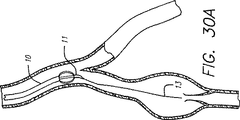
図30aに示すようなカテーテル10をガイドワイヤ13に沿って静脈系に導入する。カテーテル10の作業端11の先端部15は、ガイドワイヤ上及び静脈系中の曲げ部を通って移動するために可撓性であるノーズコーンの形態をしている。図30bに示すように、カテーテル10を、機能不全弁を含む拡張静脈部分に送り込む。次に、好ましくは図30cに示すように電極12をカテーテル10から外方へ機械的に弓反りにすることによって電極を静脈壁と並置関係に配置する。電極からのRFエネルギの適用により、静脈は収縮し、外方へ弓反りになった電極によって定められるカテーテルの有効直径を機械的に減少させて静脈の収縮量を制御する。弓反りになった電極は、図30dに示すように特定の有効直径を定め、静脈の閉塞を回避するために定位置に保持される。カテーテルを拡張静脈部分の長さに沿って移動させて、拡張が広範な場合に全体的な収縮を引き起こすのがよい。
RFエネルギは、静脈の拡張を軽減するのに十分に静脈の収縮を行った後、電極からもはや適用されない。相当な程度の収縮は、適用されたRFエネルギの出力レベルを含む特定の治療条件に応じて非常に迅速に達成できる。治療部位の特性、例えば温度をモニターすると、RFエネルギのためのフィードバック制御が可能となる。他の技術、例えばインピーダンスモニタリング及び超音波パルスエコー法を自動化システムで用いてもよく、自動化システムは、静脈の十分な収縮が検出された場合、そして静脈の加熱又は焼灼を回避するために、電極から静脈部分へのRFエネルギの適用を止める。RFエネルギについての自動フィードバック制御システム内におけるこれらの値のモニタリングを用いると、出力レベル及び加熱効果を制御することができる。
静脈の十分な収縮が生じたかどうかは、透視検査、静脈造影、外部超音波走査、脈管内超音波走査、インピーダンスモニタリング、温度モニタリング、血管鏡を用いる直接視診又は任意他の適当な方法を用いて検知できる。例えば、カテーテル10を、X線造影剤を送って収縮過程中の静脈の治療部位に対するカテーテルの関係及び静脈の状態を評価するために透視検査による目視を可能にするよう構成するのがよい。透視検査に代わる手段として、種々の角度からの別個の超音波信号を用いる外部超音波技術、例えばB走査法又は脈管内超音波技術を用いて治療部位における一層多次元的な静脈収縮観察図を得てもよく、これにより静脈中の不均一な収縮の検出可能性が向上する。また、血管鏡を用いると、静脈の収縮の程度及び度合を直接視覚化して判定することができる。
カテーテルを流体送出し内腔を有するものとして設計した場合、冷却用流体を治療されている静脈のRFによる加熱中、送出し内腔を通って血液の流れまで送ることができる。送りだされた冷却用流体は、血液に対する加熱の影響を最小限に抑え、凝血が生じる程度まで血液を加熱する恐れを小さくする。流体を、作業端及び電極近傍のカテーテルの側部に沿って形成された穴を通って送るのがよい。
電極12近傍のカテーテル10の作業端11を用いると、物理的に収縮量を制限することができる。作業端11は好ましくは、静脈の完全な結紮を防止するのに十分な大きさになっており又は拡大されている。他の手段、例えば膨張可能なバルーンを用いても静脈中の収縮量を機械的に制限し又は制御することができる。また、かかる機械的手段を用いると、治療中における電極と静脈組織との並置関係を確実にすることができる。
静脈の全体的な収縮を可能にしながら、カテーテルを用いると静脈弁を一層直接治療することもできる。痔静脈は、二尖弁を有しており、正常且つ機能が完全な弁では、各弁尖は、血液の嚢又はリザーバを形成し、この溜まりは圧力を受けて弁尖の表面を互いに押し合うようにし、それにより血液の逆流を防止すると共に心臓への順行性の流れだけを可能にする。図29に示すように、下大静脈IVCの頂部及び上痔静脈SHVから出ている矢印は、心臓へ戻る血液の順行性の流れを示している。静脈弁は、血液が静脈管腔を通って前へ押され、心臓に戻る時に逆行性の流れを防止する。機能不全弁では、弁尖は、正しくシールせず、血液の逆行性の流れが生ずる場合がある。機能不全弁は、拡張静脈の引き伸しに起因する場合がある。弁が働かないと、下方の静脈及び静脈の下方の弁に加わる圧力が増大し、これにより、これら下方の弁の働きが一層悪くなる。痔核は、その結果として生じ、さらに悪化する場合がある。弁尖は、静脈壁が弁尖のところで薄くなって引き伸ばされることにより、交連のところで或る程度の分離を生じる場合がある。RFエネルギを機能不全状態の静脈弁の近傍で拡張静脈内に適用すると、静脈が収縮し、これにより、静脈弁の正しい機能を妨げている拡張状態が減少することによって弁の完全閉鎖機能を回復させることができる。
静脈弁の治療に当たり、カテーテルに設けられている電極を、静脈弁の尖との接触が透視検査、超音波又は他の検出方法によって観察されるまで前進させる。次に、カテーテルを僅かに引き戻して静脈の拡張部分の治療を行うことができるようにする。電極を作動させてRFエネルギを静脈組織に送り出し、静脈を収縮させる。RFエネルギの適用は、弁尖の意図しない加熱を回避するよう制御すべきである。静脈の収縮を制限して静脈の閉塞を防止すると共にその機能を発揮し続けさせるのがよい。カテーテル又は伸長自在な部材の外径を制御すると、静脈の収縮の大きさを制限することができる。
治療後、静脈弁の交連及び弁尖を分離又は脱病状を殆ど生じずに互いに近接することが必要であり、それにより、弁の完全閉鎖状態の回復が分かる。弁の完全閉鎖機能が得られたかどうかは、造影剤注入又はドップラープローブ測定法により判定できる。例えば、ラジオパク造影溶液をカテーテル内腔中に注入すると、下降静脈造影法を介して弁の完全閉鎖機能を評価できる。機能不全状態の静脈弁を含む部分の上の一部の全体的な収縮内により静脈の拡張を減少させることにより、弁に加わる静脈圧及び静脈の拡張を減少させることによって(これにより、弁尖の所要スパンが減少する)弁の完全閉鎖機能を回復させることができることは注目されるべきである。また、静脈弁を横切る電極の直接的な配置により、ルーズでばたばたと動く葉状片の収縮を収縮させることができ、それにより脱出を防止すると共に弁を通る血液の逆流を防止する。
カテーテル10を、必要なだけの数の静脈部分及び静脈弁を治療するよう静脈内に再配置することができる。RFエネルギを修復されるべき各静脈部分に適用し、ついには所望の静脈部分が全て修復され、静脈弁を完全に機能するようにする。多数の機能不全状態の静脈弁及び拡張静脈部分を侵襲が最小の単一の手順で治療し修復することができる。所望ならば、第2の導入器を患者に挿入して、他の静脈系、例えば上痔静脈中の機能不全状態の静脈部分を治療することができる。
本発明による治療に適した静脈機能不全の別の領域としては、食道静脈瘤が挙げられる。食道静脈瘤と呼ばれる拡張蛇行静脈は、下部食道の粘膜下組織に沿って静脈系中に生じる場合があり、出血が腫脹した静脈から発生する場合がある。正しく寸法決めされたカテーテルを本発明にしたがって用いると電極を食道静脈瘤に沿って静脈機能不全部位に送ることができる。カテーテルの脈管内接近は好ましくは、上腸間膜静脈又は門静脈を通って行われ、それにより下部食道に通じる門静脈枝管を収縮させる。電極を静脈内に正しく位置決めしたかどうかは、透視検査又は超音波技術を用いて確認できる。電極はRFエネルギ又は他の放射エネルギを適当な周波数で適用して静脈の機能を維持しながら静脈を収縮させると共に静脈の腫脹及び食道周囲の静脈への高い門静脈圧力の伝達量を減少させる。静脈の収縮量は、カテーテルの直径によって制限でき、或いは電極それ自体を所定の直径に拡張させることができ、この所定の直径は静脈の収縮をその直径に制限する。
食道静脈瘤と呼ばれる拡張蛇行静脈は、下部食道の粘膜下組織に沿って静脈系中に生じる場合があり、出血が腫脹した静脈から発生する場合がある。正しく寸法決めされたカテーテル10を本発明にしたがって用いると電極12を食道静脈瘤に沿って静脈機能不全部位に送ることができる。カテーテルの脈管内接近は好ましくは、上腸間膜静脈又は門静脈を通って行われ、それにより下部食道に通じる門静脈枝管を収縮させる。電極を静脈内に正しく位置決めしたかどうかは、透視検査又は超音波技術を用いて確認できる。電極はRFエネルギ又は他形態のエネルギを適当な周波数で適用して静脈の機能を維持しながら静脈を収縮させると共に腫脹及び食道周囲の静脈への高い門静脈圧力の伝達量を減少させる。静脈の収縮量は、カテーテルの直径によって制限でき、或いは電極それ自体を所定の直径に拡張させることができ、この所定の直径は静脈の収縮をその直径に制限する。
下部食道領域の静脈を治療する際、接近部位に対して手術前準備を行い、経皮導入器を静脈中へ挿入する。機能不全状態の静脈の修復のための手順は、有資格医師が透視検査による案内又は超音波による観察又は直接的な視覚化によって達成できる。ガイドワイヤ13を経皮導入器を介して静脈中へ通し、この中を静脈治療部位まで前進させる。ワイヤを静脈治療部位、例えば修復されるべき最も近くに位置する機能不全状態の静脈部位のレベルまで前進させる。好ましくは、ガイドワイヤ及びカテーテルを順行方向に食道治療部位まで前進させる。変形例として、カテーテルを静脈中に直接挿入してガイドワイヤを用いないで操作してもよい。
図31に示すように、食道領域に通じる静脈系の部分図では、カテーテル10をガイドワイヤ13に沿って静脈の拡張部分まで前進させる。カテーテル及びガイドワイヤを送る一方法は、ガイドワイヤを上腸間膜静脈SMVを通して門静脈PV及び冠静脈CVに導入することであり、この冠静脈CVは枝わかれして下部食道Eに通じて食道静脈EVを形成している。別の経路として、ガイドワイヤを下腸間膜静脈中へ導入し、脾静脈SV、門静脈PV及び冠静脈CVを通って導き、治療されるべき食道静脈瘤のところに到達させることができる。
ガイドワイヤを展開して操作し、食道静脈瘤を治療するための治療部位に到達させる。静脈治療部位は好ましくは、拡張静脈の管腔内に位置している。次に、カテーテル10を図31に示すようにガイドワイヤ13上でこれに沿って静脈治療部位に送り出す。透視検査、X線、超音波又はこれと類似した映像化技術を用いると、カテーテルの特定の位置を決めると共に静脈内の位置を確認することができる。X線造影剤をカテーテルの中又はこの周りに注入すると、治療されるべき拡張静脈部分がどこにあるかがわかる。痔核又は食道静脈瘤の出血もまた、この方法によって突き止めることができる。
いったん拡張静脈部分に達すると、1又は2以上の電極12を作動させてRFエネルギを拡張静脈部分に適用する。電極を静脈の中心内に維持している間、電極を好ましくは静脈壁に並置させる。電極を静脈組織に並置させることにより、加熱効果を血液中を流れている血液にではなく、静脈組織に向かって送り出し、それにより静脈の収縮の制御が可能になる。並置関係を達成する一方法は、電極をカテーテルの本体から外方へ弓反りにすることである。これは、図32a,図32b及び図32cに示されている。電極は、静止部分及び可動部分に取り付けられた互いに反対側の端部をカテーテルの作業端に有する細長い長手方向構造部材を有している。弓反り自在な電極を作動させるには、カテーテルの先端を静止状態に保ったままカテーテルの外側スリーブを移動させる。変形例として、中央ワイヤを用いて、弓反り自在な電極の反対側の端部を定位置に保った状態で、先端部を移動させてもよい。
カテーテル10の作業端11のところの一又は二以上の電極12は、いったん静脈治療部位に位置決めされると、RFエネルギを適用して静脈の収縮を生じさせる。RF発生器を作動させて好ましくは低電力レベル、且つ好ましくは250kHz〜350MHzの範囲の選択された周波数で適当なRFエネルギを発生する。例えば、適当な一周波数は510kHzである。適用する周波数の選択のための一判断基準は、組織中の加熱作用の広がり(深さを含む)を制御することにある。もう1つの判断基準は、熱電対信号からRFノイズを除くために使用できる濾波回路との適合性である。
電極から放出されたエネルギは、静脈組織内で熱に変換される。静脈組織の温度が上昇すると、静脈組織は収縮を始める。収縮は一つには脱水及び静脈中の膠原繊維の構造的変化に起因する。膠原繊維はこの過程中、押し固められたようになるが、血管壁膠原繊維は依然として弾性を保持している。
相当な程度の収縮は、適用されたRFエネルギの出力レベルを含む特定の治療条件に応じて非常に迅速に達成できる。治療部位の特性、例えば温度をモニターすると、RFエネルギのためのフィードバック制御が可能となる。他の技術、例えばインピーダンスモニタリング及び超音波パルスエコー法を自動化システムで用いてもよく、自動化システムは、静脈の十分な収縮が検出された場合、そして静脈の加熱又は焼灼を回避するために、電極から静脈部分へのRFエネルギの適用を止める。RFエネルギについての自動フィードバック制御システム内におけるこれらの値のモニタリングを用いると、出力レベル及び加熱効果を制御することができる。
静脈の十分な収縮が生じたかどうかは、透視検査、外部超音波走査、脈管内超音波走査、インピーダンスモニタリング、温度モニタリング、血管鏡を用いる直接視診又は任意他の適当な方法を用いて検知できる。例えば、カテーテル10を、X線造影剤を送って収縮過程中の静脈の治療部位に対するカテーテルの関係及び静脈の状態を評価するために透視検査による目視を可能にするよう構成するのがよい。透視検査に代わる手段として、種々の角度からの別個の超音波信号を用いる外部超音波技術、例えばB走査法又は脈管内超音波技術を用いて治療部位における一層多次元的な静脈収縮観察図を得てもよく、これにより静脈中の不均一な収縮の検出可能性が向上する。また、血管鏡を用いると、静脈の収縮の程度及び度合を直接視覚化して判定することができる。
電極12の近傍のカテーテル10の作業端11は、収縮量を物理的に制限する。作業端11のところの電極12は、外方へ弓反りになって静脈壁と並置状態になり、次に、RFエネルギの適用中、カテーテルに向かって内方に徐々に減少する。作業端11のところの電極12の最終有効直径は好ましくは、静脈の完全な閉塞を防止するのに十分なものである。他の手段、例えば膨らまし自在なバルーンを用いても、静脈中の収縮量を所望直径に機械的に制限又は制御することができる。RFエネルギは、静脈の拡張をなくすのに十分な静脈の収縮が生じた後、電極からもはや適用されない。上述の機械的な方法以外の方法を用いても、静脈の収縮の大きさを制御することができる。かかる機械的な方法としては、静脈RF治療の時間及び温度を制御することが挙げられる。
拡張静脈部分を、本発明によるRFエネルギの制御された適用のもとで、加熱して正常な又は減少した直径に収縮させる。拡張静脈の連続軸方向部分を治療するには、拡張静脈部分が広範囲にわたっていたとしても、拡張静脈部分に沿ってRFエネルギを適用できる。広範な静脈部分を治療するためには、カテーテルを時間の間隔をおいて移動させて静脈部分を徐々に収縮させ、或いはRFエネルギの適用中、広範な部分に沿って前後に移動させる。さらに、静脈が厚くなることが治療中に生じる場合があり、これは静脈の拡張及び出血の再発の恐れを減少させる。
RFエネルギの適用により、食道静脈瘤の拡張部が収縮し、収縮を広げて門静脈系中の他の部分を含ませることは、食道静脈瘤に加わる静脈圧の増大の効果を一段と減少させる上で有利である。食道静脈は、門静脈系からの圧力に敏感である。食道前の静脈の広い部分に沿う全体的な収縮による食道前の門静脈の枝管の治療は、門静脈系からの圧力の増大によって生じる食道静脈に及ぼされる拡張効果が減少する場合がある。
他の機構を用いても電極をカテーテル反れ自体から弓反りにしたり又は拡張して遠ざけることなく、電極を修復されるべき静脈部分に対して正しく位置決めし、又は並置させることができることは理解されるべきである。カテーテルは、電極の正しい配置状態が得られるよう偏向でき、トルクを加えることができ又は他の方法で移動できるようにするのがよい。カテーテルは、作業端近傍で制御できる曲げ部を有するよう製造するのがよい。例えば、曲げ部を形状記憶合金から作るのがよく、ワイヤシステム、トルクを加えることができるブレード又は恒久的な曲げ部をカテーテル内に設けてこれによって操作することができるようにしてもよい。カテーテルの作業端を走査することにより、所望ならば、電極を静脈壁の一方の側に近付けて配置している場合治療中の静脈壁に沿って優先的又は選択的にに加熱を行うことができる。また、静脈の優先的な加熱を用いると、止血を行うことができる。
双極性構成について説明したが、単極形構成も使用できることは理解されるべきである。単極形構成では、内側の電極、例えばメッシュ又はワイヤ電極は、患者体内の腔内へ挿入される。内側電極よりも表面積の大きい外側電極が、治療部位の近くで患者の身体の外面上に配置される。例えば、外部金属プレートが、内側電極によって治療されるべき領域上で皮膚の上に置かれる。電極は、患者の体内に電界を作るRF発生器に接続されている。内側電極の表面積は外側電極の表面性よりも非常に小さいので、電界密度は、内側電極の周りにでは一層高い。電界は、2つの電極の間で内側電極近傍の領域において最も局い密度に達する。内側電極の周りの電界密度の増加により、内側電極を包囲している組織の局部的な加熱が可能となる。加熱の度合は、加熱されている組織のインピーダンス及び誘電率のような要因で決まる。電極の互いに異なる個数及び形態を用いても所望の随意的な加熱効果を生じさせることができることは理解されるべきである。
本願の開示内容から容易に確かめることができるように、本発明の方法は、長期の入院又は術後回復を必要とすることなく達成できる。静脈機能の治療修復は、ライフスタイルの変化を続ける必要なく、例えばしばしば足を挙上した状態、比較的不快な弾性サポートストッキングを装着すること又は再発性静脈うっ血性潰瘍の長期間にわたる治療を行う必要なく可能である。さらに、静脈の外科的移植は不要である。
静脈瘤疾患の初期の治療は、より重い合併症、例えば潰瘍、血栓性静脈炎、及び血栓塞栓症を防止することができる。静脈瘤疾患に起因する治療及び合併症のコストは、著しく減少する。この手術のための長期入院は不要であり、その後の治療及び入院の必要は現在必要な程度から減少する。さらに、本発明の方法は侵襲が最小に抑えられているので、医療従事者は比較的短時間で単一の手術により幾つかの静脈部分を修復又は治療することができる。
カテーテル及び電極のタイプ及び寸法形状を、治療されるべき静脈のサイズによって選択できることは理解されるべきである。本発明を、下肢の静脈機能不全、例えば脚中の拡張蛇行静脈を治療するものとして説明したが、本発明は身体の他の領域中の静脈機能不全を管腔内手法的に治療するために用いることができる。
別の静脈機能不全領域は、陰茎の勃起不能症に関する。相当な数の物理的な理由により生じた不能症のケースは全て、陰茎静脈系からの血液の角のドレナージに起因している。静脈ドレナージ不能症は、本発明を用いて治療可能である。十分に小さな直径を有するカテーテルを用いると、電極を陰茎静脈系の背部静脈中に送り込んでこの静脈流出経路を収縮させる。透視検査又は超音波法を用いると、電極を機能不全静脈内に正しく位置決めすることができる。RFエネルギ又は他の輻射エネルギを電極から適当な周波数で適用して静脈機能又は弁の完全閉鎖機能を維持しながら周囲の静脈組織を収縮させる。その目的は、陰茎からの過度のドレナージ量を減少させることにある。静脈の収縮量をカテーテル自体の直径により制限でき、或いは、カテーテル又は電極それ自体を適当なサイズまで拡張させても良い。正しい陰茎機能を得るのに必要な充血状態の陰茎からの血液の適切なドレナージを行えるようこれら静脈の結紮を回避する必要がある。
本発明の幾つかの特定の実施形態を図示説明したが、本発明の精神及び範囲から逸脱することなく種々の設計変更を想到できることは明らかであろう。したがって、本発明の範囲は、特許請求の範囲に記載の事項にのみ基づいて定められる。 Background of the Invention
The present invention releases energy and contracts the vein intraluminally in a manner that alters the mechanical behavior of the fluid flow to restore full closure of the venous valve and proper functioning of the vein with minimal invasiveness. The present invention relates to a catheter utilization system for positioning an electrode to be made.
The venous system of a person's lower limb consists essentially of a superficial venous system and a deep venous system, and a penetrating vein (penetrating branch) connects these two venous systems. The superficial venous system includes long or large saphenous veins and short saphenous veins. The deep vein system includes ventral and dorsal tibial veins that are integrated to form the popliteal vein, which becomes the femoral vein when joined by a short saphenous vein.
The venous system has many one-way valves that allow blood flow back to the heart. Venous valves are usually bicuspid valves, where each leaflet forms a sac or reservoir of blood that presses against the free surfaces of the leaflets under pressure, thereby preventing retrograde flow of blood. And allows antegrade flow to the heart. If a dysfunctional or dysfunctional valve is in an antegrade flow path towards the foot, such a dysfunctional valve cannot be closed because the leaflets do not form a proper seal. Inability to block the retrograde flow of blood.
Malfunctioning valves in the venous system may occur with venous dilation symptoms. As a result, venous valve leaflet separation occurs at commissure. The leaflets are stretched by the expansion of the vein and the accompanying increase in vein diameter. The stretching of the leaflet of the venous valve causes the loose leaflet to fold and leave the valve open. This prolapse may cause blood backflow in the vein. Eventually, the venous valve becomes dysfunctional, thereby increasing the pressure applied to the underlying venous portion and the tissue located thereon. Two venous diseases that often occur as a complication of venous dilatation are dilated tortuous veins and chronic venous insufficiency.
Symptoms of dilated serpentine veins include dilation of the superficial venous system of the lower limbs and meandering, resulting in unsightly discoloration, pain and ulcers. As a complication of dilated serpentine veins, one or more venous valve dysfunctions may result, resulting in the backflow of blood from the deep venous system to the superficial venous system or backflow within the superficial venous system. Current treatments include invasive open surgical procedures such as: stripping, sclerotherapy, and in some cases, vein transplantation, venous valve formation, various prostheses The device is implanted. Removal of the dilated meander veins from the body is a tedious and time consuming operation that is tedious and slow to heal. Complications, scar scars, and loss of veins in preparation for future heart and other bypass procedures may also result. Not only are there complications and the risk of invasive open surgery, but dilated serpentine veins may persist or recur, especially if problems related to valve dysfunction are not resolved. Because surgery is time consuming, tiring, and tedious, many vein treatments may exceed the physical stamina limit of the physician, thus providing complete treatment for dilated meander veins Impossible.
Chronic venous insufficiency (CVI) is a disease caused by hydrodynamic pressure acting on body tissues, particularly the lower limbs, ankles and feet. When the vein expands due to increased pressure, the valve in the vein becomes dysfunctional. This adds pressure to the next valve with increased pressure, depressing the valve portion, thereby dilating these veins, and if this continues, all the valves in the vein eventually fail. When these venous valves fail, the effective height of the blood column above the foot and ankle increases, increasing the weight and static pressure of the blood column on the ankle and foot tissue. As the blood column weight reaches the brink of whether venous valve dysfunction occurs, an ankle ulcer begins to develop, starting deep and eventually reaching the surface. Ulcers do not heal easily. This is because the weight of the blood column that caused the ulcer acts continuously as it is and tends to enlarge the ulcer.
Chronic venous insufficiency often results from hypertonicity in the deep veins, penetrating veins and often superficial veins of the lower extremities, which can result in discoloration, pain, swelling or swelling and ulceration. Existing treatments for chronic venous insufficiency often do not reach ideal levels. These treatments include leg elevation, external venous compression with an elastic support hose, and surgical repair by transplanting a healthy valved vein segment from the arm to the leg. In addition, invasive surgery has associated life-threatening and costly complications. Similarly, the use of waiting therapy forces the patient to make significant changes in lifestyle. For example, if the patient continues to raise the leg and use the support hose throughout his life, the ulcer will recur.
Current surgical treatments, such as transplantation, typically treat only one valve in a single procedure because they are time consuming and invasive. This places significant constraints on the physician in fully treating patients with chronic venous insufficiency. However, every invasive surgery has associated life-threatening and expensive complications.
Methods such as ligation of venous lumens by wrapping and tying sutures around veins, cauterization or coagulation using electrical energy from electrodes have been used as an alternative to removal methods or surgical removal of such veins. However, the ligation method closes the lumen and specifically destroys these functions. For example, it is known to introduce an electrode into a patient's leg to position the electrode adjacent to the exterior of the dilating serpentine vein to be treated. From a small incision, the probe is inserted into the subcutaneous layer between the fascia and the skin and then pushed to the dilating serpentine vein to be removed. An electrode provided at the outer end of the probe is disposed adjacent to the dilating serpentine vein. Once properly positioned, a 500 kHz alternating current is applied to destroy the adjacent dilating serpentine vein. Veins lose their ability to circulate blood and can no longer be used. For example, if the saphenous vein is ligated, the saphenous vein cannot be collected during other surgical procedures, such as coronary artery bypass surgery. A ligation technique that destroys the venous lumen in terms of function appears to be inappropriate as a corrective procedure to restore or maintain venous function.
Hemorrhoids are dilated venous plexuses inside and around the anus and lower rectum. Dilation may occur due to increased pressure on the vaginal vein. Constipation with frequent stipulation to pass hard stool increases pressure in the vaginal vein, which is a common cause of hemorrhoids. As the vaginal vein expands further due to increased pressure, the vein valve of the vaginal vein becomes dysfunctional due to dysfunction. This exacerbates the expansion of the vaginal vein. This is because an open dysfunctional valve causes blood backflow in the vein. If this condition persists, the vein may eventually form a sac-like process. Hemorrhoids are generally classified as either inner hemorrhoids or outer hemorrhoids depending on their position relative to the tooth line. The dentate line is simply the mucocutaneous junction. The dentate line separates the inner heel tissue from the outer heel tissue. The internal hemorrhoid is located inside the anus above the dentate line. The outer hemorrhoid is located below the dentate line. Any hemorrhoid can protrude from the anus.
Tension or irritation during defecation may damage the delicate surface of the internal hemorrhoids and cause bleeding. As the vaginal vein continues to increase and dilate, the internal hemorrhoids can prolapse and be pushed out of the anal hole. If the hemorrhoids remain prolapsed, the result is considerable discomfort such as pruritus or bleeding. The blood supply to these prolapsed hemorrhoids is blocked by the anal sphincter, which results in strangulated hemorrhoids. As a result, thrombosis occurs where the blood in the escape vein becomes a clot. This very painful condition can cause edema and inflammation.
In addition, an increase in pressure in the portal vein system may increase the pressure in the superior vena cava (SHV), which causes an increase in the diameter of the hemorrhoid. The portal venous system allows for venous drainage from the intestinal tissue to the liver, which can lead to hypertension when the liver becomes cirrhotic.
Examples of methods for treating hemorrhoids include invasive surgery for removing hemorrhoids, ligation using an elastic ring, sclerotherapy, and topical medicine or suppository. This surgical removal of extensive or severe hemorrhoids is known as hemorrhoidectomy. This surgical procedure is available for internal and external hemorrhoid therapy. However, such surgery generally involves risks and high costs resulting from invasive surgery and a long recovery period.
Internal hemorrhoids can be treated by ligating with a rubber band where the ligator is inserted into the anal canal through the scope. The internal hemorrhoid is pinched with a ligator forceps and held in place. The ligator has a cylindrical body that slides upward and winds one or more rubber bands around the base of the hemorrhoid. A typical diameter of the rubber band is 1 mm. The rubber band blocks blood circulation to the hemorrhoids, so the hemorrhoids begin to atrophy. If the rubber band is held in place, hemorrhoids usually fall off within 7-10 days.
Another hemorrhoid treatment, sclerotherapy, injects a solution such as sodium morrhuate or phenol oil into the loose connective tissue around the vaginal vein under the mucosa to cause inflammation and scarring. To eliminate hemorrhoids. Other external treatments cause cauterization or coagulation to destroy the hemorrhoids. In coagulation with infrared, infrared light is used to stop the blood supply to the hemorrhoid by creating a small tissue destruction burn around the base of the hemorrhoid. Electrocoagulation (which is sometimes called bipolar diathermy therapy) can be used as well. In laser therapy (which may also be referred to as evaporation), the laser beam creates a superficial burn to close the blood vessel and hold the hemorrhoid in a non-escape position.
Conventional hemorrhoid treatments, including ligation or excision from the outside of the hemorrhoids, do not affect the root of the disease, so that the hemorrhoid condition occurs first. Thus, the symptoms recur.
Dilated serpentine veins called esophageal varices may occur in the venous system along the submucosa of the lower esophagus. Blood returns from the portal venous system through the veins around the esophagus to the heart. Unlike other veins, such as the saphenous veins of the lower limbs, veins around the esophagus generally do not have a valve to return blood to the heart. Because the venous pressure in these saphenous veins is relatively high, blood can return to the heart without a venous valve.
Esophageal varices may result from portal hypertension and other abnormalities in the portal venous system, such as cirrhosis. Bleeding can occur due to esophageal varices, which is difficult to stop and, if not treated, can develop and become life threatening. Such varicose veins are fragile and cause large amounts of fire extinguisher bleeding.
Treatment of esophageal varices includes portal vein-vena cava bypass formation, endoscopic vein ligation, sclerotherapy, and electrocoagulation from electrodes located within the esophagus, such as tampon insertion devices. In portal vein-vena cava bypass formation, a surgical joint between two veins, the portal vein and the inferior vena cava, is used to reduce the pressure in the vein that carries blood to the liver. Although effective in preventing the recurrence of bleeding due to varicose veins, the risks and complications associated with such invasive surgery (including brain damage and liver dysfunction after bypass formation) still exist with portal vein bypass surgery. ing.
Endoscopic vein ligation is similar to rubber band ligation for hemorrhoid treatment. Capturing esophageal varices with elastic bands to eradicate varices. An endoscope is introduced into the patient's body and placed adjacent to the varicose vein to be treated. The varicose vein is drawn into a drum attached to the tip of the endoscope. Next, the elastic band attached to the drum is released onto the varicose vein. Endoscopic venous ligation cannot achieve complete fibrosis of the inner wall of the esophagus and may result in recurrence of varicose veins. Other complications include ulceration with elastic bands and esophageal closure due to lumen occlusion with esophageal varices with elastic bands.
In sclerotherapy, for example, sodium morhuate or ethanolamine is injected submucosally into the tissue around the dilated serpentine vein of the esophagus, thereby causing inflammation and scarring to close the vein and eliminate the risk of bleeding. However, sclerotherapy results in the formation of ulcers that can cause esophageal stenosis.
Electrocoagulation has also been used to treat esophageal varices. A tampon insertion device with a metallized surface is introduced into the esophagus. Contact the metallized surface with the esophageal mucosa. Next, an electric current is passed through the metallized surface to create an esophageal varices thrombus. With this procedure, immediate bleeding of esophageal varices can be stopped.
Conventional treatment of esophageal varices generally involves blood clotting or occlusion of the veins from the outside, and often requires a large number of treatments. Such treatment cannot directly treat varicose-like swelling or varicosity, and does not affect the root, so esophageal varices occur first.
Treats dilated veins, such as dilated serpentine veins, or dilated veins due to venous dysfunction, maintains venous patency for normal venous function, and restores full valve closure There is a need in the art for a system. There is also a need in the art for a technique that treats an expanded vaginal vein to reduce the venous pressure applied to the hemorrhoid region. Such treatment should maintain venous function patency and restore the complete valve closure function of the vaginal vein as well as the hemorrhoid itself. There is a need in the art for a technique that reduces the venous pressure applied from the portal venous system to the esophageal region by treating the dilated vein that causes esophageal varices without the attendant risks of invasive surgery. Furthermore, there is a need to provide a minimally invasive surgical method that can quickly and easily treat many venous sites. There is a need to restore and normalize flow patterns, hydrodynamic behavior, and pressure, and to contract the dilated vein segment to a normal or reduced diameter. When bleeding occurs, there is a need to achieve hemostasis of the bleeding varicose vein and to minimize bleeding recurrence.
Summary of the Invention
In summary, the present invention provides a less invasive and rapid method for solving the fundamental problems of dilated serpentine veins and venous dysfunction, and emits radio frequency (hereinafter "RF") energy. Use a novel repair system that includes a catheter for placement of the device. The present invention is a method of applying energy to cause contraction of a vein, the step of introducing a catheter having a working end and a heating means provided at the working end to a treatment site in the vein, and the heating means in the vein Positioning at the treatment site, applying energy from the heating means to heat the treatment site to cause venous contraction, and after sufficient contraction of the vein, stop applying energy from the heating means Allowing the vein to remain patented so that it can function as a blood conduit. The method of the present invention is a minimally invasive procedure that eliminates the need for open surgery to perform venous repairs, including venous valvuloplasty and brachial vein implantation into the leg.
An apparatus used to implement a method for deflating a vein using radiant energy is provided at a working end and a catheter having an outer diameter smaller than the inner diameter of the vein, and at the working end of the catheter to reduce the venous contraction. It consists of a heating device that can heat the venous treatment site to cause and control means to control the contraction of the vein so that the vein remains patent so that it can perform its venous function. The heating means may include an RF electrode that heats and contracts the vein. The amount of contraction may be limited using a balloon or other mechanism for adjusting the outer shape of the heating means. A feedback control system may be applied to these mechanisms to control the amount of contraction, or the feedback control system may be used to control the application of energy to heat the venous tissue.
Features of the present invention include restoration of the full closure function of the venous valve, flow pattern, mechanical behavior with respect to flow, and normalization of pressure, reduction of the expanded serpentine vein portion to normal diameter for cosmetic purposes. It is done. Treated veins remain patent, continue to function normally, and can return blood to the heart.
Another feature of the present invention is to provide a method for restoring the full closure function of a venous valve by controllably contracting a venous expansion lumen to a desired diameter.
Another feature of the present invention is that the effective diameter of the catheter or electrode is adjusted to control the amount of circumferential contraction that occurs in the vein wall. An extensible member disposed adjacent to the working end of the catheter can increase the diameter of the catheter and limit the amount of venous contraction.
Yet another feature of the present invention is to circumferentially and omnidirectionally constrict the vein wall while minimizing longitudinal shrinkage when positioned in the vein in an endoluminal manner. The object is to provide a catheter electrode that creates an RF field or range of action around the lumen.
Yet another feature of the present invention is the generation of a specific frequency field around the catheter in order to control the spread of the heating effect in the venous tissue with minimal clotting in the vein.
Another feature of the present invention is to protect the venous leaflets by minimizing the heating effect on the venous valve by selective positioning of the electrodes in the vein.
Another feature of the present invention is that the cooling fluid is pumped into the bloodstream to reduce the risk of heating the blood to the extent that it causes clotting.
Another feature of the present invention is to prevent venous constriction beyond the end of the catheter.
Another feature of the present invention is that the electrode is maintained in juxtaposition to or attached to the venous tissue, and heat is pumped toward the venous tissue, for blood flowing through the vein. It is to prevent it from working.
Another feature of the present invention is the use of an electrode that is a bowable member that can be deflected radially outward to maintain contact with venous tissue. The bowable member is a conductive longitudinal electrode that is substantially coated with an insulating film except for the portion that should be in juxtaposition with the venous tissue.
Another feature of the present invention is that a balloon is provided on one side of the catheter and an electrode is provided on the other side. By inflating (inflating) the balloon, the electrode will move and juxtapose with the vein wall on the other side.
Yet another feature of the present invention is to provide a method that can quickly and easily treat multiple venous sites.
Another feature of the present invention is that no foreign bodies or debris remain in the vasculature or vasculature after treatment.
These and other features and advantages of the present invention will become apparent upon reading the following detailed description with reference to the accompanying drawings, which are merely illustrative of the principles of the invention.
[Brief description of the drawings]
FIG. 1 is a cross-sectional view of a dilated vein having a dysfunctional venous valve in the lower limb to be treated according to the present invention.
FIG. 2 is a perspective view of the vein portion from FIG. 1 at line 2-2 to be treated according to the present invention.
FIG. 3 is a partial cross-sectional view of a catheter with electrodes delivered to a venous treatment site in an antegrade direction in accordance with the present invention.
4 is a partial cross-sectional view of the vein portion of FIG. 2 after treatment in accordance with the present invention.
5 is a partial cross-sectional view of the catheter and vein shown in FIG. 3 delivered to another treatment site in accordance with the present invention.
FIG. 6 is a partial cross-sectional view of a catheter that has been sent to a venous treatment site in a retrograde direction and deflected laterally in accordance with the present invention.
FIG. 7 is a partial cross-sectional view of an embodiment of a catheter with a bulbous tip and a ring electrode for treating dilated veins according to the present invention.
FIG. 8 is a partial cross-sectional view of an embodiment of a catheter with a flush tip at the working end and a ring electrode for treating dilated veins in accordance with the present invention.
FIG. 9 is a partial cross-sectional view of an embodiment of a catheter with a cap electrode for treating dilated veins in accordance with the present invention.
FIG. 10 is a partial cross-sectional view of another embodiment of a catheter with a cap electrode and a balloon for centering the placement of the electrode within the vein to be treated.
FIGS. 11a, 11b and 11c are partial cross-sectional views of another embodiment of a catheter with a bendable tip that laterally deflects so that the electrode and vein wall of the catheter are juxtaposed with each other in accordance with the present invention. is there.
Figures 12a and 12b include a balloon on one side of the catheter and a longitudinal electrode on the other side of the working end of the catheter, and the electrode is moved according to the present invention to place it in juxtaposition with the vein wall It is a partial cross-sectional side view and a partial cross-sectional plan view, respectively, of another embodiment of the catheter to be caused.
FIG. 13 illustrates another embodiment of a catheter with a bendable electrode that deflects outward to increase the effective diameter of the working end of the catheter in accordance with the present invention.
FIG. 14 shows another embodiment of a catheter with a balloon that can be bent outwardly deflected to increase the effective diameter of the working end of the catheter and a balloon in accordance with the present invention.
15a is a cross-sectional view of the embodiment of the catheter shown in FIG. 14 with four electrodes spaced equally according to the present invention.
FIG. 15b is a cross-sectional view of the embodiment of the catheter shown in FIG. 14 with four electrodes preferentially spaced to form two pairs of electrodes in accordance with the present invention.
FIG. 16 is a partial cross-sectional view of another embodiment of a catheter comprising four electrodes spaced equally and delivered to a venous treatment site in a retrograde direction in accordance with the present invention.
FIG. 17 is a partial cross-sectional view of an embodiment of an overwire catheter comprising four electrodes spaced equally on the surface of a balloon according to the present invention.
18 is a cross-sectional view taken along line 18-18 of the overwire catheter of FIG. 17 according to the present invention.
FIG. 19 is a partial cross-sectional view of another embodiment of a catheter comprising an electrode provided in a balloon portion according to the present invention.
FIG. 20 is a side view of an embodiment of a catheter with a bowable electrode according to the present invention combined with a block diagram of a heat treatment system.
21 is a partial side view of the working end of the catheter shown in FIG. 20 with electrodes deflecting outward to increase the effective diameter of the working end of the catheter in accordance with the present invention.
22 is a cross-sectional view taken along line 22-22 of the catheter electrode shown in FIG.
FIG. 23 is a cross-sectional view taken along line 23-23 of FIG. 20 and shows a catheter with four equally spaced electrodes according to the present invention.
FIG. 24 is a cross-sectional view of another embodiment of the catheter shown in FIG. 23, which has four electrodes that are preferentially spaced to form two pairs of electrodes according to the present invention. It is a figure of the state provided with.
FIG. 25 is a cross-sectional view of another embodiment of the catheter shown in FIG. 23, with this embodiment comprising two pairs of opposed electrodes according to the present invention.
26 is a cross-sectional view of the catheter taken along line 26-26 in FIG.
Figure 27 is a partial side view of the working end of another embodiment of a catheter with a balloon and a bendable member with electrodes according to the present invention.
28 is a cross-sectional view taken along line 28-28 in FIG.
FIG. 29 is a partial cross-sectional view of the venous system of the hemorrhoid region treated according to the present invention.
Figures 30a, 30b, 30c and 30d are side views of an embodiment of a catheter for treating a venous treatment site in a dilated vein in accordance with the present invention.
FIG. 31 is a partial side view of an anatomical region of an esophageal region with a vein treated according to the present invention.
FIGS. 32a, 32b and 32c are side views of an embodiment of a catheter configured to perform treatment according to the present invention and delivered to a venous treatment site in a dilated vein.
Detailed description of embodiments
As shown in the exemplary drawings, the present invention relates to intravenous venous treatment using a catheter that delivers at least one electrode to a venous treatment site. In this specification, the same code | symbol has shown the same element in various embodiment of this invention demonstrated below. In addition, unless otherwise specified, the “working end” refers to the direction toward the treatment site within the patient, and the term “connecting end” refers to the direction away from the treatment site within the patient. The present invention will be described in connection with the treatment of the limb venous system. However, the invention is not so limited and can be used intraluminally to treat veins in other areas of the body, such as hemorrhoids, esophageal varices, penile venous drainage (impotence) Can be used. Furthermore, although the present invention is described as using RF energy from an electrode, other forms of energy can be used, such as microwaves, ultrasound, direct current, circulating heating fluid, synchrotron radiation, and laser, It should be understood that the thermal energy generated from the resistance coil or Curie point element can be used as well.
A partial cross-sectional view of a dilated vein of the lower limb with a dysfunctional valve is shown in FIG. These veins are often in muscle tissue. The vein has a bicuspid valve, and in a normal and intact valve, each leaflet forms a blood sac or reservoir that presses the free ends of the leaflets together under pressure to reverse blood. Prevents sexual flow and allows only antegrade flow to the heart. The upward arrow of the vein indicates the antegrade flow of blood back to the heart. The venous valve prevents retrograde flow as blood is pushed forward through the venous lumen and back to the heart.
If the malfunctioning valve is subjected to retrograde flow, the valve cannot close and the valve leaflets cannot be properly sealed and a retrograde flow of blood may occur. A dysfunctional valve may be due to expansion of dilated blood vessels. If the valve does not work, increased pressure is exerted on the lower veins and the valves below the veins, thereby exacerbating the dysfunction of these lower valves. A cross-sectional perspective view of the dilated vein taken along line 2-2 of FIG. 1 is shown in FIG. The leaflets may be pulled apart somewhat at the commissure as the vein wall is thinned and stretched at the leaflets.
The minimally invasive method of treating venous dysfunction of the present invention can be accomplished by using the
When treating the veins of the lower limbs, the patient generally rests on the treatment table with his feet lowered. The purpose is to fill the leg veins with blood. Prepare the patient's leg with antiseptic solution. A percutaneous introducer is inserted into the vein using the well-known Seldinger technique to access the saphenous vein system or the deep vein system. Alternatively, a vein to be treated may be accessed using phlebotomy. Procedures for repair of dysfunctional valves can be performed by qualified physicians with or without fluoroscopic or ultrasonic observation, or under direct visualization. Further, when treating the superficial venous system, the physician can palpate the treatment site during surgery to determine where the catheter is and where the treatment site is.
The
In an antegrade approach, the catheter may be pushed into the venous valve so that the electrode is positioned across the valve in the dysfunctional venous portion to be treated. The
The working
After RF energy applied from
After treatment, the venous valve commissures and leaflets need to be separated from each other with little or no pathological condition, thereby revealing a recovery of the fully closed state of the valve. A cross-sectional view of the venous valve after treatment with RF energy is shown in FIG. Whether or not the valve has been fully closed can be determined by contrast medium injection or Doppler probe measurement.
Depending on the specific treatment conditions, a considerable degree of contraction can be achieved very quickly. Since contraction can occur at a much faster rate, RF energy is preferably applied at a low power level. As described above, the frequency of the RF energy is selected to minimize clotting and control the spread of the heating effect at the treatment site. The nature of the treatment site, such as temperature, should be monitored to allow feedback control for RF energy, the purpose being to minimize clotting. Automation of other techniques, such as impedance monitoring and ultrasonic pulse echo, to stop applying RF energy from the electrodes to the venous portion to avoid venous overheating or cauterization when sufficient venous contractions are detected You may use for an apparatus. Also, by monitoring these values with an automatic feedback controller for RF energy, the spread (including depth) of the heating effect can be controlled. In all cases, the application of RF energy is controlled to contract the venous tissue sufficiently to restore and maintain the full closure function of the venous valve.
After treatment of the venous portion shown in FIG. 3, the
If the catheter is designed to have a fluid delivery lumen, the cooling fluid can be delivered through the delivery lumen to the blood flow during RF heating of the vein being treated. The delivered cooling fluid minimizes the effects of heating on the blood and reduces the risk of heating the blood to the extent that clotting occurs. Fluid may be routed through a hole formed along the side of the catheter near the working end and electrodes.
Although the method of the present invention has been described above as restoring the full closure function of a valve, the present invention is not limited thereto. Treatment of adjacent axial portions of a dilated vein can be treated by applying RF energy along the dilated vein portion, even if it is extensive. The dilated vein is deflated under a controlled application of RF energy according to the present invention to a normal diameter state. Such treatment can be used in the cosmetic treatment of dilated serpentine veins. Furthermore, during treatment, the veins can become thicker, which can reduce the risk of recurrence of dilated meander veins and venous dysfunction.
The
Instead of the antegrade system as shown in FIGS. 3 and 5, the catheter can deliver electrodes to the venous treatment site from a retrograde direction. The
Applying RF energy more specifically to commissures that are in venous valve isolation is effective in restoring venous function and full valve closure function.
A deflected
After treatment of a portion of the vein, the catheter may be moved to the level of the next portion of the vein to be treated. Next, the same procedure is repeated to repair veins one after another. The treatment is repeated several times until eventually a sufficient contraction is achieved to restore the venous function and the full closure function of the valve while maintaining the patency of the vein. When treatment of the dysfunctional vein portion is complete, the catheter containing the electrode is removed from the vein.
An embodiment of a
The
Although the
Although a bipolar configuration has been described, it should be understood that a monopolar configuration can also be used. In a monopolar configuration, an inner electrode, such as a mesh or wire electrode, is inserted into a cavity within the patient. An outer electrode having a larger surface area than the inner electrode is placed on the outer surface of the patient's body near the treatment site. For example, an external metal plate is placed on the skin over the area to be treated by the inner electrode. The electrodes are connected to an RF generator that creates an electric field in the patient's body. Since the surface area of the inner electrode is much smaller than the surface properties of the outer electrode, the electric field density is much higher around the inner electrode. The electric field reaches the highest density in the region near the inner electrode between the two electrodes. The increase in electric field density around the inner electrode allows local heating of the tissue surrounding the inner electrode. The degree of heating depends on factors such as the impedance and dielectric constant of the tissue being heated.
As a modification, the
As an alternative to the detection electrode or thermistor, as another embodiment, an ultrasonic piezoelectric element that emits pulsed ultrasonic waves is used as the
The working
Another embodiment of the
In another embodiment, an
As described in connection with FIG. 6, it may be desirable to maintain selective juxtaposition of electrodes and venous tissue at the treatment site. The embodiment of the
Another embodiment uses an
In another embodiment, as shown in FIG. 13, the
The degree of contraction can be controlled by the effective diameter when the catheter and electrode are combined. The
The
Another embodiment of the
A
A cross-sectional view of
In a variation of the embodiment described in connection with FIG. 14, the
In another embodiment, the end of the elongated electrode attached to the sleeve instead of the outer sleeve is slidably disposed within a longitudinal slot or channel provided along the circumference of the catheter. The ends of the bowable members will slide toward the working end in these channels when they are deflected outward or bowed, retracted back toward the connecting end, and thereby Return to their original form.
In another variation, a single wire mesh or braided electrode may be used instead of the electrode and elongated member, preferably when RF energy is applied in a monopolar configuration. As before, the balloon extends the mesh electrode radially outward and juxtaposes it against the vein wall. The balloon can also control the amount of vein contraction.
Another way to change the effective diameter of the catheter of FIGS. 13 and 14 is to move the
Other devices that are controllably inflatable or expandable can also be used to limit venous contraction to the desired size. For example, the mandrel may be advanced through the side of the catheter to set a diameter limit for contraction of the venous portion. Alternatively, a bow deflectable conductive deflection wire may be provided on one side of the catheter to achieve a juxtaposition with the vein wall. Furthermore, the non-inflatable catheter shaft and electrode shown in FIG. 7 can also be used to limit the amount of vein contraction during surgery. The vein will simply contract to the constant diameter of the catheter.
Other methods can be used on the catheter to maintain the juxtaposition relationship. For example, a pressure cuff may be used to apply external pressure to the leg to compress the treatment area so that the vein wall contacts the electrode. The juxtaposition of the electrode and venous tissue is maintained by applying external pressure. Such external compression can be used in the treatment of superficial veins. The magnitude of venous contraction can be controlled using a method other than the mechanical method described above. Such non-mechanical methods include controlling the time and temperature of venous RF treatment.
When the working end of the
Another way to control heat transfer to achieve more uniform heating is to use an external compression or tourniquet to reduce blood flow or compress the vein around the catheter at the venous treatment site. is there. By reducing blood flow, either through external compression or an occlusion balloon inflated in an intravascular manner, the effect of blood flow through the veins (which can carry heat away from the treatment site) is minimized. It can be suppressed. The effect of heat transfer to venous tissue during surgery is diminished by blood flow, and thus the rate of venous contraction is more predictable. Also, sufficient pressure can be obtained by the external compression band, thereby placing the vein in juxtaposition with the electrode.
In another embodiment, such as that shown in FIG. 16, an
While not limited to the embodiment using the occlusion balloon shown in FIG. 16, the
The balloon inflatable embodiment as shown in FIG. 17 has four
In another embodiment, the
Another embodiment of a
The
The degree of contraction is controlled by the effective diameter of the combined catheter and electrode.
The
The bow-warpable longitudinal electrode is conductive over its entire length, and an insulating
The exposed area of the electrode is preferably the area that directly contacts the vein wall during juxtaposition. In this case, the heating effect is concentrated on the vein wall. The exposed surface area of the electrode should be as large as possible while maintaining a constant distance between the exposed portions of the electrode along the circumference of the effective diameter. The wider the exposed surface of the electrodes that are juxtaposed against the vein during contraction, the greater the surface area of the vein wall that is affected by the electric field generated by the electrode. The exposed area of the electrode should be substantially flat to enhance uniform contact with the vein wall and control the diameter of the vein.
A
A cross-sectional view of the
In another embodiment, the RF field can be more directionally concentrated using two pairs of electrodes arranged to be isolated from each other. For example, as shown in FIG. 25, the positive electrodes of each electrode pair are adjacent to each other and no field is created around the effective diameter between the two pairs of electrodes. Opposing RF fields are created by two pairs of electrodes, thereby creating two separate heating zones along the periphery. These heated areas can be directed to cause heating at an isolated area (ie, not circumferential) within the vein, thereby treating a specific area of varicose bleeding from the vein. Specific or isolated cases of varicose bleeding can be treated by applying RF energy directional to the vein.
The working end of the catheter further has a guide wire lumen 39 for receiving the
Another embodiment of the
In one embodiment, the
In another embodiment, the end of the elongated electrode is slidably disposed within a longitudinal slot or channel provided along the circumference of the catheter. The ends of the bowable members will slide toward the working end in these channels when they are deflected outward or bowed, retracted back toward the connecting end, and thereby Return to their original form.
In another variation, a single wire mesh or braided electrode may be used instead of the electrode and elongated member, preferably when RF energy is applied in a monopolar configuration. As before, the balloon extends the mesh electrode radially outward and juxtaposes it against the vein wall. The balloon can also control the amount of vein contraction.
Another way to change the effective diameter of the catheter is to move or deflect the electrode so that it directly contacts the vein wall, which in turn allows the vein wall to change the effective diameter. As the electrode releases RF energy, the vein wall contracts and pushes the electrode inward toward the catheter. Due to the venous contraction, the effective diameter is reduced directly rather than by the physician's active control, thereby eliminating the need for mechanical constant fine adjustments to the effective diameter. Devices such as push rods or constant diameter balloons are used to prevent further radial contraction of the electrode at a particular effective diameter, thereby controlling and limiting the amount of venous contraction. This has the advantage of maintaining the electrodes in juxtaposed relationship with the venous tissue, so that the tissue is heated above the surrounding blood, in which case the physician constantly adjusts the effective diameter of the catheter while applying RF energy. Is not required.
The inventive method for treating minimally invasive vein failure can be accomplished using a catheter that delivers at least one electrode at the working end of the catheter to the venous treatment site. Its purpose is to restore the correct functioning of the veins leading to the hemorrhoid area. With an overwire or overrail wire guide catheter, one or more electrodes can be delivered to the hemorrhoid treatment site through tortuous bends in the venous system.
The electrodes are used to constrict, reinforce, and secure the veins, and to coagulate the RF energy to a minimum at the appropriate frequency for a period of time sufficient to maintain venous function or full valve closure function. Apply to the mass. This endoluminal approach avoids the risk of morbidity associated with more invasive procedures such as hemorrhoid resection and significantly reduces blood reflux in this area without necrotizing or removing venous tissue.
When treating the vein in the lower hemorrhoid area, preparation is made before the operation at the approach site, and a percutaneous introducer is inserted into the vein. Treatment for repair of dysfunctional veins can be accomplished by a qualified physician by fluoroscopy guidance, ultrasound observation or direct visualization. The guide wire is passed through the vein through the percutaneous introducer and advanced to the venous treatment site. As a variant, the catheter may be inserted directly into the vein and operated without a guide wire. The guidewire preferably has a spring wound tip. The guidewire is advanced in the retrograde direction to the venous treatment site, eg, the farthest dysfunctional venous site to be repaired. Several intravenous routes to the hemorrhoid treatment site can be taken.
A partial cross-sectional view of the venous system leading to the hemorrhoid region is shown in FIG. Hemorrhoids are generally defined as inner hemorrhoids or outer hemorrhoids, respectively, depending on whether they are formed above or below the dentate line DL. The internal hemorrhoid IH is usually formed when the narrower vein that feeds blood to the superior or intermediate hemorrhoid vein SHV becomes dilated. External hemorrhoids usually occur when a narrow vein that feeds blood into the inferior vena cava vein IHV dilates.
One way to deliver the
Another way of delivering the catheter and guide wire is to introduce the guide wire into the superior vein and manipulate the guide wire to deliver it through the superior vena cava SHV to the hemorrhoid region. The guide wire is manipulated to place it in the correct position, and then the catheter is routed along the guide wire to the venous treatment site for internal hemorrhoids. The venous treatment site is located within the lumen of the dilated vein.
Once the
The energy released from the electrode is converted to heat in the venous tissue. As the temperature of the venous tissue increases, the venous tissue begins to contract. Shrinkage is due in part to dehydration and structural changes in the collagen fibers in the veins. While the collagen fibers become consolidated during this process, the vascular wall collagen fibers still retain elasticity.
Application of RF energy can heat the dilated vein site of the hemorrhoid. The dilated vein contracts to a normal or reduced diameter state under controlled application of RF energy that heats the venous tissue. The venous pressure exerted on the inferior vein portion of the hemorrhoid can be reduced by reducing the cross-sectional area of the vein. The full closure function of the valve in the inferior vein portion may be indirectly restored by a decrease in venous pressure. Also, thickening of the veins occurs during treatment, which can reduce the risk of recurrence of venous dilatation. Also, controlling the temperature and output of the RF energy can cause the hemorrhoids to contract and allow the wall of the vaginal vein to stick to the adjacent tissue.
Application of RF energy can cause the venous dilation to contract near the site of hemorrhoid formation, but expanding the contraction to include a wider venous part further reduces the effect of increasing venous pressure on the hemorrhoidal tissue This is advantageous. The continuous axial portion of the dilated vein can be treated by applying RF energy along the dilated vein portion, even if this portion is extensive. For example, hemorrhoids are sensitive to pressure from the portal system that can be transmitted to the hemorrhoid through the superior vena cava SHV. Treatment of the superior vaginal vein by global contraction along a wide portion of the vein above the hemorrhoid can counteract the expansion force resulting from increased pressure from the portal system. Such treatment may be desirable even if there is not much dilation in the superior vena cava SHV.
A
RF energy is no longer applied from the electrode after venous contraction is sufficient to reduce venous dilation. A considerable degree of contraction can be achieved very quickly depending on the specific treatment conditions including the applied RF energy power level. Monitoring the characteristics of the treatment site, such as temperature, allows feedback control for RF energy. Other techniques, such as impedance monitoring and ultrasonic pulse echo, may be used in the automated system, and the automated system detects if sufficient venous contraction is detected and to avoid venous heating or cauterization. The application of RF energy to the venous portion is stopped. With monitoring these values in an automatic feedback control system for RF energy, power levels and heating effects can be controlled.
Whether or not sufficient vein contraction has occurred can be determined using fluoroscopy, venography, external ultrasound scanning, intravascular ultrasound scanning, impedance monitoring, temperature monitoring, direct visual inspection using an angioscope or any other suitable method. Can be detected. For example, the
If the catheter is designed to have a fluid delivery lumen, the cooling fluid can be delivered through the delivery lumen to the blood flow during RF heating of the vein being treated. The delivered cooling fluid minimizes the effects of heating on the blood and reduces the risk of heating the blood to the extent that clotting occurs. Fluid may be routed through a hole formed along the side of the catheter near the working end and electrodes.
When the working
A catheter can also be used to treat the venous valve more directly while allowing for overall contraction of the vein. The vaginal vein has bicuspid valves, and in normal and fully functioning valves, each leaflet forms a blood sac or reservoir that presses against the surface of the leaflets together. Fit, thereby preventing backflow of blood and allowing only antegrade flow to the heart. As shown in FIG. 29, the arrow coming out from the apex of the inferior vena cava IVC and the superior vena cava SHV indicates the antegrade flow of blood back to the heart. The venous valve prevents retrograde flow as blood is pushed forward through the venous lumen and back to the heart. With dysfunctional valves, the leaflets do not seal properly and a retrograde flow of blood may occur. A dysfunctional valve may result from stretching of the dilated vein. If the valves do not work, the pressure on the lower veins and the valves below the veins will increase, which makes the lower valves work worse. Hemorrhoids result and can become worse. The leaflets may cause some separation at the commissure as the vein wall is thinned and stretched at the leaflets. When RF energy is applied in the dilated vein in the vicinity of a dysfunctional venous valve, the veins contract, thereby restoring the fully closed function of the valve by reducing dilated conditions that are preventing proper functioning of the venous valve Can be made.
In treating a venous valve, the electrode on the catheter is advanced until contact with the venous valve apex is observed by fluoroscopy, ultrasound, or other detection method. The catheter is then pulled back slightly to allow treatment of the venous dilation. The electrode is activated to deliver RF energy to the venous tissue, causing the vein to contract. The application of RF energy should be controlled to avoid unintentional heating of the leaflets. It is desirable to restrict vein contraction to prevent vein occlusion and continue to function. Controlling the outer diameter of the catheter or extendable member can limit the amount of venous contraction.
After treatment, the venous valve commissures and leaflets need to be separated from each other with little or no pathological condition, thereby revealing a recovery of the fully closed state of the valve. Whether or not the valve has been fully closed can be determined by contrast medium injection or Doppler probe measurement. For example, when radiopac contrast solution is injected into the catheter lumen, the full closure function of the valve can be assessed via descending venography. By reducing the venous pressure and venous expansion on the valve by reducing the venous dilation within some of the overall contraction over the part containing the dysfunctional venous valve (the valve leaflet It should be noted that the fully closed function of the valve can be restored. Also, the direct placement of the electrodes across the venous valve allows contraction of the loose flapping and moving leaf-like pieces, thereby preventing escape and backflow of blood through the valve.
The
Another area of venous dysfunction suitable for treatment according to the present invention includes esophageal varices. Dilated serpentine veins, called esophageal varices, can occur in the venous system along the submucosal tissue of the lower esophagus, and bleeding can originate from swollen veins. A correctly sized catheter can be used in accordance with the present invention to deliver electrodes along the esophageal varices to the site of venous dysfunction. The intravascular access of the catheter is preferably made through the superior mesenteric vein or portal vein, thereby deflating the portal vein branch leading to the lower esophagus. Whether the electrodes are correctly positioned in the vein can be confirmed using fluoroscopy or ultrasound techniques. The electrodes apply RF energy or other radiant energy at an appropriate frequency to constrict the vein while maintaining venous function and reduce venous swelling and high portal vein pressure transmission to the peri-esophageal vein. The amount of vein contraction can be limited by the diameter of the catheter, or the electrode itself can be expanded to a predetermined diameter, which limits the contraction of the vein to that diameter.
Dilated serpentine veins, called esophageal varices, can occur in the venous system along the submucosal tissue of the lower esophagus, and bleeding can originate from swollen veins. Using a correctly
When treating the veins in the lower esophagus region, pre-surgery preparations are made at the access site and a percutaneous introducer is inserted into the vein. Procedures for repair of dysfunctional veins can be accomplished by a qualified physician with fluoroscopic guidance or ultrasound observation or direct visualization. A
As shown in FIG. 31, in a partial view of the venous system leading to the esophageal region, the
The guidewire is deployed and manipulated to reach the treatment site for treating esophageal varices. The venous treatment site is preferably located within the lumen of the dilated vein. Next, the
Once the dilated vein portion is reached, one or
Once positioned at the venous treatment site, one or
The energy released from the electrode is converted to heat in the venous tissue. As the temperature of the venous tissue increases, the venous tissue begins to contract. Shrinkage is due in part to dehydration and structural changes in the collagen fibers in the veins. While the collagen fibers become consolidated during this process, the vascular wall collagen fibers still retain elasticity.
A considerable degree of contraction can be achieved very quickly depending on the specific treatment conditions including the applied RF energy power level. Monitoring the characteristics of the treatment site, such as temperature, allows feedback control for RF energy. Other techniques, such as impedance monitoring and ultrasonic pulse echo, may be used in the automated system, and the automated system detects if sufficient venous contraction is detected and to avoid venous heating or cauterization. The application of RF energy to the venous portion is stopped. With monitoring these values in an automatic feedback control system for RF energy, power levels and heating effects can be controlled.
Whether sufficient vein contraction has occurred can be detected using fluoroscopy, external ultrasound scanning, intravascular ultrasound scanning, impedance monitoring, temperature monitoring, direct visual inspection using an angioscope, or any other suitable method. For example, the
The working
The dilated vein portion is heated and contracted to a normal or reduced diameter under the controlled application of RF energy according to the present invention. To treat the continuous axial portion of the dilated vein, RF energy can be applied along the dilated vein portion, even if the dilated vein portion is extensive. To treat a wide venous portion, the catheter is moved at time intervals to gradually contract the venous portion, or moved back and forth along the wide portion during application of RF energy. In addition, thickening of the veins may occur during treatment, which reduces the risk of venous dilatation and bleeding recurrence.
By applying RF energy, the expansion of the esophageal varices contracts and widens the contraction to include other parts of the portal venous system, further reducing the effect of increasing venous pressure on the esophageal varices. Is advantageous. The esophageal vein is sensitive to pressure from the portal venous system. Treatment of the branch of the pre-esophageal portal vein by global contraction along a wide portion of the pre-esophageal vein may reduce the dilation effect exerted on the esophageal vein caused by increased pressure from the portal venous system.
It is understood that other mechanisms can be used to properly position or juxtapose the electrode relative to the vein portion to be repaired without bowing or expanding the electrode away from the catheter bow itself. Should. The catheter can be deflected to provide the correct placement of the electrodes, can be torqued or otherwise moved. The catheter should be manufactured with a bend that can be controlled near the working end. For example, the bend may be made from a shape memory alloy, and a wire system, a blade capable of applying torque, or a permanent bend may be provided in the catheter for manipulation. By scanning the working end of the catheter, if desired, heating can be performed preferentially or selectively along the vein wall being treated when the electrode is placed close to one side of the vein wall. it can. In addition, hemostasis can be performed using preferential heating of veins.
Although a bipolar configuration has been described, it should be understood that a monopolar configuration can also be used. In a monopolar configuration, an inner electrode, such as a mesh or wire electrode, is inserted into a cavity within the patient. An outer electrode having a larger surface area than the inner electrode is placed on the outer surface of the patient's body near the treatment site. For example, an external metal plate is placed on the skin over the area to be treated by the inner electrode. The electrodes are connected to an RF generator that creates an electric field in the patient's body. Since the surface area of the inner electrode is much smaller than the surface properties of the outer electrode, the electric field density is much higher around the inner electrode. The electric field reaches the most local density in the region near the inner electrode between the two electrodes. The increase in electric field density around the inner electrode allows local heating of the tissue surrounding the inner electrode. The degree of heating depends on factors such as the impedance and dielectric constant of the tissue being heated. It should be understood that different optional numbers and configurations of electrodes can be used to produce the desired optional heating effect.
As can be readily ascertained from the disclosure of the present application, the method of the present invention can be achieved without the need for long-term hospitalization or post-operative recovery. Therapeutic repair of venous function does not require continued lifestyle changes, for example, often with a raised foot, wearing relatively uncomfortable elastic support stockings, or long-term treatment of recurrent venous stasis ulcers It is possible without need. Furthermore, no surgical implantation of veins is necessary.
Early treatment of varicose disease can prevent heavier complications such as ulcers, thrombophlebitis, and thromboembolism. The cost of treatment and complications due to varicose disease is significantly reduced. Long-term hospitalization for this operation is unnecessary, and the need for subsequent treatment and hospitalization is reduced from what is currently needed. Furthermore, because the method of the present invention is minimally invasive, medical personnel can repair or treat several vein portions in a relatively short time with a single operation.
It should be understood that the type and dimensions of the catheter and electrode can be selected depending on the size of the vein to be treated. Although the present invention has been described as treating venous dysfunction of the lower extremities, such as dilating serpentine veins in the leg, the present invention is intended to treat venous dysfunction in other areas of the body in an endoluminal manner. Can be used.
Another area of venous dysfunction relates to penile impotence. All cases of impotence caused by a considerable number of physical reasons are due to drainage of blood horns from the penile venous system. Impotence of venous drainage can be treated using the present invention. With a sufficiently small diameter catheter, an electrode is fed into the dorsal vein of the penile venous system to constrict this venous outflow pathway. Using fluoroscopy or ultrasound, the electrode can be correctly positioned in the dysfunctional vein. RF energy or other radiant energy is applied from the electrodes at the appropriate frequency to contract the surrounding venous tissue while maintaining venous function or the full closure function of the valve. The purpose is to reduce the amount of excessive drainage from the penis. The amount of venous contraction can be limited by the diameter of the catheter itself, or the catheter or electrode itself can be expanded to an appropriate size. It is necessary to avoid ligation of these veins so that proper drainage of blood from the congested penis necessary for proper penis function can be achieved.
While several specific embodiments of the invention have been illustrated and described, it will be apparent that various design changes can be made without departing from the spirit and scope of the invention. Therefore, the scope of the present invention is defined based only on the matters described in the claims.
Claims (9)
前記装置は、
作業端を有し、かつ、静脈の内径よりも小さな外径を有するカテーテル(10)を備えており、前記カテーテル(10)は、さらに、可動の外側スリーブ(36)を有しており、
前記装置は、さらに、RF場を形成し、かつ、静脈の直径を減少させるように静脈の治療部位を加熱することができる加熱装置(12)を備え、前記加熱装置(12)は、前記カテーテル(10)の前記作業端に設けられており、
前記装置は、さらに、前記加熱装置(12)を前記カテーテル(10)の外方に移動させることができ、また、前記加熱装置(12)を前記カテーテル(10)に向かって引き戻すことができるようになっている複数の弓反り自在な部材(32)を備え、前記弓反り自在な部材(32)は導電性であり、前記弓反り自在な部材(32)は、更に、非被覆部分を除き、前記導電性である弓反り自在な部材(32)の表面を被覆する絶縁性フィルム(35)を含み、前記非被覆部分は、前記弓反り自在な部材(32)を前記カテーテル(10)から外方へ移動させたときに静脈壁に接触するようになっており、前記弓反り自在な部材(32)の各々は、第1の端部と、第2の端部とを有しており、前記第1の端部は、前記カテーテル(10)の前記作業端に連結されており、前記第2の端部は、前記可動の外側スリーブ(36)に連結されており、前記外側スリーブを操作することにより、前記弓反り自在な部材(32)の前記非被覆部分を移動させて静脈に並置させることができるようになっており、
前記加熱装置(12)は、前記導電性である弓反り自在な部材の非被覆部分を含むようになっており、
前記弓反り自在な部材(32)は、前記弓反り自在な部材(32)により定まる有効直径を越える静脈の直径の減少を阻止するほど十分な構造的な強さを有している、
ことを特徴とする装置。A device that applies energy to reduce the diameter of a vein and cause contraction of the vein,
The device is
A catheter (10) having a working end and having an outer diameter smaller than the inner diameter of the vein, the catheter (10) further comprising a movable outer sleeve (36);
The device further comprises a heating device (12) capable of heating the treatment site of the vein so as to create an RF field and reduce the diameter of the vein, the heating device (12) comprising the catheter (10) provided at the working end,
The device is further capable of moving the heating device (12) out of the catheter (10) and retracting the heating device (12) towards the catheter (10). A plurality of bow-warpable members (32), wherein the bow-warpable members (32) are electrically conductive, and the bow-warpable members (32) further exclude an uncovered portion An insulating film (35) covering the surface of the electrically conductive bow-warpable member (32), the uncovered portion connecting the bow-warpable member (32) from the catheter (10). Each of the bowable members (32) has a first end and a second end so as to contact the vein wall when moved outward. The first end is in front of the catheter (10) The second end is connected to the movable outer sleeve (36), and the bow of the bowable member (32) can be operated by operating the outer sleeve. The uncovered part can be moved and juxtaposed to the vein,
The heating device (12) includes an uncovered portion of the conductive bowable member;
The bowable member (32) has sufficient structural strength to prevent a reduction in vein diameter beyond the effective diameter defined by the bowable member (32).
A device characterized by that.
Applications Claiming Priority (9)
| Application Number | Priority Date | Filing Date | Title |
|---|---|---|---|
| US08/610,911 US6036687A (en) | 1996-03-05 | 1996-03-05 | Method and apparatus for treating venous insufficiency |
| US08/610,911 | 1996-03-05 | ||
| US08/720,209 US6139527A (en) | 1996-03-05 | 1996-09-26 | Method and apparatus for treating hemorrhoids |
| US08/717,994 | 1996-09-26 | ||
| US08/717,994 US6033397A (en) | 1996-03-05 | 1996-09-26 | Method and apparatus for treating esophageal varices |
| US08/720,209 | 1996-09-26 | ||
| US08/811,820 US6033398A (en) | 1996-03-05 | 1997-03-04 | Method and apparatus for treating venous insufficiency using directionally applied energy |
| PCT/US1997/003637 WO1997032532A1 (en) | 1996-03-05 | 1997-03-04 | Vascular catheter-based system for heating tissue |
| US09/483,969 US6981972B1 (en) | 1996-03-05 | 2000-01-18 | Apparatus for treating venous insufficiency using directionally applied energy |
Publications (3)
| Publication Number | Publication Date |
|---|---|
| JP2000511787A JP2000511787A (en) | 2000-09-12 |
| JP2000511787A5 JP2000511787A5 (en) | 2004-12-02 |
| JP4060887B2 true JP4060887B2 (en) | 2008-03-12 |
Family
ID=46203076
Family Applications (1)
| Application Number | Title | Priority Date | Filing Date |
|---|---|---|---|
| JP53198597A Expired - Fee Related JP4060887B2 (en) | 1996-03-05 | 1997-03-04 | Vascular catheter utilization system for heating tissue |
Country Status (6)
| Country | Link |
|---|---|
| US (3) | US6033398A (en) |
| EP (1) | EP0921765B1 (en) |
| JP (1) | JP4060887B2 (en) |
| AU (1) | AU733465B2 (en) |
| CA (1) | CA2248260C (en) |
| WO (1) | WO1997032532A1 (en) |
Families Citing this family (359)
| Publication number | Priority date | Publication date | Assignee | Title |
|---|---|---|---|---|
| JP2001508318A (en) | 1996-02-02 | 2001-06-26 | トランスバスキュラー インコーポレイテッド | Apparatus, systems and methods for interstitial transvascular intervention |
| US6036687A (en) * | 1996-03-05 | 2000-03-14 | Vnus Medical Technologies, Inc. | Method and apparatus for treating venous insufficiency |
| JP4060887B2 (en) | 1996-03-05 | 2008-03-12 | ヴィナス メディカル テクノロジーズ インコーポレイテッド | Vascular catheter utilization system for heating tissue |
| US6077257A (en) * | 1996-05-06 | 2000-06-20 | Vidacare, Inc. | Ablation of rectal and other internal body structures |
| US5891134A (en) * | 1996-09-24 | 1999-04-06 | Goble; Colin | System and method for applying thermal energy to tissue |
| US6464697B1 (en) | 1998-02-19 | 2002-10-15 | Curon Medical, Inc. | Stomach and adjoining tissue regions in the esophagus |
| US5827268A (en) * | 1996-10-30 | 1998-10-27 | Hearten Medical, Inc. | Device for the treatment of patent ductus arteriosus and method of using the device |
| US6035238A (en) * | 1997-08-13 | 2000-03-07 | Surx, Inc. | Noninvasive devices, methods, and systems for shrinking of tissues |
| US6081749A (en) * | 1997-08-13 | 2000-06-27 | Surx, Inc. | Noninvasive devices, methods, and systems for shrinking of tissues |
| US6292700B1 (en) | 1999-09-10 | 2001-09-18 | Surx, Inc. | Endopelvic fascia treatment for incontinence |
| US6091995A (en) * | 1996-11-08 | 2000-07-18 | Surx, Inc. | Devices, methods, and systems for shrinking tissues |
| US7317949B2 (en) | 1996-11-08 | 2008-01-08 | Ams Research Corporation | Energy induced bulking and buttressing of tissues for incontinence |
| AU6146798A (en) * | 1997-03-04 | 1998-09-22 | Vnus Medical Technologies, Inc. | Method and apparatus for treating venous insufficiency using directionally applied energy |
| US7425212B1 (en) * | 1998-06-10 | 2008-09-16 | Asthmatx, Inc. | Devices for modification of airways by transfer of energy |
| US7992572B2 (en) | 1998-06-10 | 2011-08-09 | Asthmatx, Inc. | Methods of evaluating individuals having reversible obstructive pulmonary disease |
| US6488673B1 (en) * | 1997-04-07 | 2002-12-03 | Broncus Technologies, Inc. | Method of increasing gas exchange of a lung |
| US6634363B1 (en) * | 1997-04-07 | 2003-10-21 | Broncus Technologies, Inc. | Methods of treating lungs having reversible obstructive pulmonary disease |
| US7027869B2 (en) | 1998-01-07 | 2006-04-11 | Asthmatx, Inc. | Method for treating an asthma attack |
| US9023031B2 (en) | 1997-08-13 | 2015-05-05 | Verathon Inc. | Noninvasive devices, methods, and systems for modifying tissues |
| US6179832B1 (en) * | 1997-09-11 | 2001-01-30 | Vnus Medical Technologies, Inc. | Expandable catheter having two sets of electrodes |
| US6258084B1 (en) | 1997-09-11 | 2001-07-10 | Vnus Medical Technologies, Inc. | Method for applying energy to biological tissue including the use of tumescent tissue compression |
| US6401719B1 (en) * | 1997-09-11 | 2002-06-11 | Vnus Medical Technologies, Inc. | Method of ligating hollow anatomical structures |
| US6200312B1 (en) * | 1997-09-11 | 2001-03-13 | Vnus Medical Technologies, Inc. | Expandable vein ligator catheter having multiple electrode leads |
| US6014589A (en) * | 1997-11-12 | 2000-01-11 | Vnus Medical Technologies, Inc. | Catheter having expandable electrodes and adjustable stent |
| US7921855B2 (en) | 1998-01-07 | 2011-04-12 | Asthmatx, Inc. | Method for treating an asthma attack |
| WO1999035983A1 (en) | 1998-01-14 | 1999-07-22 | Surx, Inc. | Ribbed electrodes and methods for their use |
| US8906010B2 (en) | 1998-02-19 | 2014-12-09 | Mederi Therapeutics, Inc. | Graphical user interface for association with an electrode structure deployed in contact with a tissue region |
| US6645201B1 (en) * | 1998-02-19 | 2003-11-11 | Curon Medical, Inc. | Systems and methods for treating dysfunctions in the intestines and rectum |
| US6358245B1 (en) | 1998-02-19 | 2002-03-19 | Curon Medical, Inc. | Graphical user interface for association with an electrode structure deployed in contact with a tissue region |
| AU752243B2 (en) | 1998-02-19 | 2002-09-12 | Curon Medical, Inc. | Electrosurgical sphincter treatment apparatus |
| US6561998B1 (en) | 1998-04-07 | 2003-05-13 | Transvascular, Inc. | Transluminal devices, systems and methods for enlarging interstitial penetration tracts |
| AU3865699A (en) * | 1998-04-22 | 1999-11-08 | Cardiosynopsis, Inc. | Apparatus to electrosurgically treating an aneurysm |
| AU3672299A (en) * | 1998-04-30 | 1999-11-16 | Stuart D Edwards | Electrosurgical sphincter treatment apparatus |
| US6161047A (en) | 1998-04-30 | 2000-12-12 | Medtronic Inc. | Apparatus and method for expanding a stimulation lead body in situ |
| US6319241B1 (en) | 1998-04-30 | 2001-11-20 | Medtronic, Inc. | Techniques for positioning therapy delivery elements within a spinal cord or a brain |
| US6440121B1 (en) * | 1998-05-28 | 2002-08-27 | Pearl Technology Holdings, Llc. | Surgical device for performing face-lifting surgery using radiofrequency energy |
| US6391023B1 (en) * | 1998-05-28 | 2002-05-21 | Pearl Technology Holdings, Llc | Thermal radiation facelift device |
| US7494488B2 (en) * | 1998-05-28 | 2009-02-24 | Pearl Technology Holdings, Llc | Facial tissue strengthening and tightening device and methods |
| US7198635B2 (en) | 2000-10-17 | 2007-04-03 | Asthmatx, Inc. | Modification of airways by application of energy |
| US8181656B2 (en) | 1998-06-10 | 2012-05-22 | Asthmatx, Inc. | Methods for treating airways |
| US6322559B1 (en) * | 1998-07-06 | 2001-11-27 | Vnus Medical Technologies, Inc. | Electrode catheter having coil structure |
| US6024742A (en) * | 1998-08-22 | 2000-02-15 | Tu; Lily Chen | Ablation apparatus for treating hemorrhoids |
| IL125990A (en) * | 1998-08-30 | 2004-12-15 | Moshe Ein-Gal | Electrocoagulation apparatus |
| US6254601B1 (en) | 1998-12-08 | 2001-07-03 | Hysterx, Inc. | Methods for occlusion of the uterine arteries |
| WO2000051511A1 (en) * | 1999-03-02 | 2000-09-08 | Atrionix, Inc. | Positioning system for a pulmonary ostium ablator |
| GB2333964B (en) * | 1999-03-04 | 1999-12-29 | Falah Hasan Ali | Intravenous coagulation catheter for treatment of varicose veins |
| EP1281366B1 (en) * | 1999-06-23 | 2006-10-11 | Novasys Medical, Inc. | Treatment of sphincters with electrosurgery and active substances |
| US6425853B1 (en) * | 1999-06-23 | 2002-07-30 | Stuart D. Edwards | Treating body tissue by applying energy and substances with a retractable catheter and contained cooling element |
| DE60044531D1 (en) * | 1999-06-25 | 2010-07-22 | Vahid Saadat | TISSUE TREATMENT DEVICE |
| EP1210024A1 (en) | 1999-09-08 | 2002-06-05 | Curon Medical, Inc. | System for controlling a family of treatment devices |
| WO2001018616A2 (en) | 1999-09-08 | 2001-03-15 | Curon Medical, Inc. | System for controlling use of medical devices |
| JP2003508150A (en) | 1999-09-08 | 2003-03-04 | キューロン メディカル,インコーポレイテッド | Systems and methods for monitoring and controlling use of medical devices |
| US20040215235A1 (en) | 1999-11-16 | 2004-10-28 | Barrx, Inc. | Methods and systems for determining physiologic characteristics for treatment of the esophagus |
| US20060095032A1 (en) | 1999-11-16 | 2006-05-04 | Jerome Jackson | Methods and systems for determining physiologic characteristics for treatment of the esophagus |
| DE60044179D1 (en) * | 1999-12-28 | 2010-05-27 | Sony Corp | System and method for the commercial traffic of images |
| US6699237B2 (en) * | 1999-12-30 | 2004-03-02 | Pearl Technology Holdings, Llc | Tissue-lifting device |
| AU2594801A (en) * | 1999-12-30 | 2001-07-16 | Pearl Technology Holdings, Llc | Face-lifting device |
| ES2643763T3 (en) | 2000-03-06 | 2017-11-24 | Salient Surgical Technologies, Inc. | Fluid supply system and controller for electrosurgical devices |
| US6558385B1 (en) | 2000-09-22 | 2003-05-06 | Tissuelink Medical, Inc. | Fluid-assisted medical device |
| US8048070B2 (en) | 2000-03-06 | 2011-11-01 | Salient Surgical Technologies, Inc. | Fluid-assisted medical devices, systems and methods |
| US6689131B2 (en) * | 2001-03-08 | 2004-02-10 | Tissuelink Medical, Inc. | Electrosurgical device having a tissue reduction sensor |
| US7811282B2 (en) | 2000-03-06 | 2010-10-12 | Salient Surgical Technologies, Inc. | Fluid-assisted electrosurgical devices, electrosurgical unit with pump and methods of use thereof |
| US8251070B2 (en) | 2000-03-27 | 2012-08-28 | Asthmatx, Inc. | Methods for treating airways |
| US7090645B2 (en) | 2000-04-04 | 2006-08-15 | Nv Thermocore Medical Systems Sa | Biased vascular temperature measuring device |
| JP4433560B2 (en) * | 2000-04-11 | 2010-03-17 | ソニー株式会社 | Terminal device and information processing method |
| US7223279B2 (en) * | 2000-04-21 | 2007-05-29 | Vascular Control Systems, Inc. | Methods for minimally-invasive, non-permanent occlusion of a uterine artery |
| US6550482B1 (en) * | 2000-04-21 | 2003-04-22 | Vascular Control Systems, Inc. | Methods for non-permanent occlusion of a uterine artery |
| US20030120306A1 (en) * | 2000-04-21 | 2003-06-26 | Vascular Control System | Method and apparatus for the detection and occlusion of blood vessels |
| US6773428B2 (en) * | 2000-05-12 | 2004-08-10 | Stephen M. Zappala | Implantable delivery system and method for the pharmacologic management of erectile dysfunction |
| US8845632B2 (en) | 2000-05-18 | 2014-09-30 | Mederi Therapeutics, Inc. | Graphical user interface for monitoring and controlling use of medical devices |
| US6508784B1 (en) * | 2000-05-19 | 2003-01-21 | Yan-Ho Shu | Balloon catheter having adjustable centering capabilities and methods thereof |
| DE20009426U1 (en) * | 2000-05-26 | 2001-10-31 | Desinger Kai | Surgical instrument |
| US20030204188A1 (en) * | 2001-11-07 | 2003-10-30 | Artemis Medical, Inc. | Tissue separating and localizing catheter assembly |
| US7534242B2 (en) * | 2003-02-25 | 2009-05-19 | Artemis Medical, Inc. | Tissue separating catheter assembly and method |
| WO2001097897A1 (en) * | 2000-06-20 | 2001-12-27 | Starion Instruments, Inc. | Devices and methods for repair of valves in the human body |
| US6695878B2 (en) | 2000-06-26 | 2004-02-24 | Rex Medical, L.P. | Vascular device for valve leaflet apposition |
| US6676698B2 (en) * | 2000-06-26 | 2004-01-13 | Rex Medicol, L.P. | Vascular device with valve for approximating vessel wall |
| US6527800B1 (en) | 2000-06-26 | 2003-03-04 | Rex Medical, L.P. | Vascular device and method for valve leaflet apposition |
| US20050107738A1 (en) * | 2000-07-21 | 2005-05-19 | Slater Charles R. | Occludable intravascular catheter for drug delivery and method of using the same |
| US7077836B2 (en) * | 2000-07-21 | 2006-07-18 | Vein Rx, Inc. | Methods and apparatus for sclerosing the wall of a varicose vein |
| US20050113798A1 (en) * | 2000-07-21 | 2005-05-26 | Slater Charles R. | Methods and apparatus for treating the interior of a blood vessel |
| US20030120256A1 (en) * | 2001-07-03 | 2003-06-26 | Syntheon, Llc | Methods and apparatus for sclerosing the wall of a varicose vein |
| US7306591B2 (en) | 2000-10-02 | 2007-12-11 | Novasys Medical, Inc. | Apparatus and methods for treating female urinary incontinence |
| US7104987B2 (en) | 2000-10-17 | 2006-09-12 | Asthmatx, Inc. | Control system and process for application of energy to airway walls and other mediums |
| JP4180382B2 (en) * | 2000-11-07 | 2008-11-12 | アーテミス・メディカル・インコーポレイテッド | Tissue separation assembly and tissue separation method |
| US6575623B2 (en) * | 2000-11-10 | 2003-06-10 | Cardiostream, Inc. | Guide wire having extendable contact sensors for measuring temperature of vessel walls |
| US6638286B1 (en) | 2000-11-16 | 2003-10-28 | Vascular Control Systems, Inc. | Doppler directed suture ligation device and method |
| US6635065B2 (en) * | 2000-11-16 | 2003-10-21 | Vascular Control Systems, Inc. | Doppler directed suture ligation device and method |
| EP1335677B1 (en) * | 2000-11-16 | 2007-11-14 | BARRX Medical, Inc. | System of treating abnormal tissue in the human esophagus |
| US8038708B2 (en) | 2001-02-05 | 2011-10-18 | Cook Medical Technologies Llc | Implantable device with remodelable material and covering material |
| US7354444B2 (en) * | 2001-03-28 | 2008-04-08 | Vascular Control Systems, Inc. | Occlusion device with deployable paddles for detection and occlusion of blood vessels |
| US20030120286A1 (en) * | 2001-03-28 | 2003-06-26 | Vascular Control System | Luminal clip applicator with sensor |
| JP4227415B2 (en) * | 2001-03-28 | 2009-02-18 | ヴァスキュラー・コントロール・システムズ・インコーポレーテッド | Method and apparatus for detecting and ligating uterine arteries |
| US6928320B2 (en) | 2001-05-17 | 2005-08-09 | Medtronic, Inc. | Apparatus for blocking activation of tissue or conduction of action potentials while other tissue is being therapeutically activated |
| US20040015159A1 (en) * | 2001-07-03 | 2004-01-22 | Syntheon, Llc | Methods and apparatus for treating the wall of a blood vessel with electromagnetic energy |
| US20060009740A1 (en) * | 2001-08-28 | 2006-01-12 | Michael Higgins | Multiple lumen catheter having a soft tip |
| US7127291B2 (en) * | 2002-03-01 | 2006-10-24 | Cardiac Pacemakers, Inc. | Coronary sinus lead with thermal sensor and method therefor |
| US7361830B2 (en) * | 2002-03-21 | 2008-04-22 | Rtd Company | Polymer encapsulated micro-thermocouple |
| US7207996B2 (en) * | 2002-04-04 | 2007-04-24 | Vascular Control Systems, Inc. | Doppler directed suturing and compression device and method |
| US9440046B2 (en) | 2002-04-04 | 2016-09-13 | Angiodynamics, Inc. | Venous insufficiency treatment method |
| US7756583B2 (en) | 2002-04-08 | 2010-07-13 | Ardian, Inc. | Methods and apparatus for intravascularly-induced neuromodulation |
| US8347891B2 (en) | 2002-04-08 | 2013-01-08 | Medtronic Ardian Luxembourg S.A.R.L. | Methods and apparatus for performing a non-continuous circumferential treatment of a body lumen |
| US7008417B2 (en) * | 2002-04-22 | 2006-03-07 | Medtronics, Inc. | Detecting coagulum formation |
| US6960203B2 (en) * | 2002-06-26 | 2005-11-01 | Ethicon, Inc. | Thermal ablation with deployable cage |
| US20080208180A1 (en) * | 2002-07-10 | 2008-08-28 | Cartier William A | Endovascular treatment sheath having a heat insulative tip and method for using the same |
| EP1539012B1 (en) * | 2002-07-10 | 2014-11-19 | AngioDynamics, Inc. | Endovascular treatment device having a fiber tip spacer |
| US20080287939A1 (en) * | 2002-07-10 | 2008-11-20 | Appling William M | Endovascular thermal treatment device with flexible guide tip and method |
| EP2134282B1 (en) | 2002-07-10 | 2019-05-22 | AngioDynamics, Inc. | Device for endovascular treatment for causing closure of a blood vessel |
| US7029467B2 (en) * | 2002-07-16 | 2006-04-18 | Edwards Lifesciences Corporation | Multiple lumen catheter having a soft tip |
| US6999809B2 (en) * | 2002-07-16 | 2006-02-14 | Edwards Lifesciences Corporation | Central venous catheter having a soft tip and fiber optics |
| EP1572020A4 (en) | 2002-10-29 | 2006-05-03 | Tissuelink Medical Inc | Fluid-assisted electrosurgical scissors and methods |
| JP2006507046A (en) * | 2002-10-31 | 2006-03-02 | クールタッチ, インコーポレイテッド | Intravenous closure of varicose veins by mid-infrared laser |
| US7921854B2 (en) | 2002-10-31 | 2011-04-12 | Cooltouch Incorporated | Endovenous laser treatment for varicose veins |
| US20040097961A1 (en) * | 2002-11-19 | 2004-05-20 | Vascular Control System | Tenaculum for use with occlusion devices |
| US7172603B2 (en) * | 2002-11-19 | 2007-02-06 | Vascular Control Systems, Inc. | Deployable constrictor for uterine artery occlusion |
| US8712549B2 (en) | 2002-12-11 | 2014-04-29 | Proteus Digital Health, Inc. | Method and system for monitoring and treating hemodynamic parameters |
| JP4528766B2 (en) * | 2003-01-24 | 2010-08-18 | プロテウス バイオメディカル インコーポレイテッド | System for remote hemodynamic monitoring |
| WO2004066817A2 (en) * | 2003-01-24 | 2004-08-12 | Proteus Biomedical Inc. | Methods and systems for measuring cardiac parameters |
| JP4557964B2 (en) | 2003-01-24 | 2010-10-06 | プロテウス バイオメディカル インコーポレイテッド | Method and apparatus for improving cardiac pacing |
| US7404821B2 (en) * | 2003-01-30 | 2008-07-29 | Vascular Control Systems, Inc. | Treatment for post partum hemorrhage |
| IES20080278A2 (en) * | 2003-01-31 | 2008-06-11 | Preton Ltd | A process for producing a performance enhanced single-layer blow-moulded container |
| US7115127B2 (en) * | 2003-02-04 | 2006-10-03 | Cardiodex, Ltd. | Methods and apparatus for hemostasis following arterial catheterization |
| US7223266B2 (en) * | 2003-02-04 | 2007-05-29 | Cardiodex Ltd. | Methods and apparatus for hemostasis following arterial catheterization |
| US7651511B2 (en) * | 2003-02-05 | 2010-01-26 | Vascular Control Systems, Inc. | Vascular clamp for caesarian section |
| US8021359B2 (en) | 2003-02-13 | 2011-09-20 | Coaptus Medical Corporation | Transseptal closure of a patent foramen ovale and other cardiac defects |
| US7257450B2 (en) * | 2003-02-13 | 2007-08-14 | Coaptus Medical Corporation | Systems and methods for securing cardiovascular tissue |
| US7333844B2 (en) * | 2003-03-28 | 2008-02-19 | Vascular Control Systems, Inc. | Uterine tissue monitoring device and method |
| US20040202694A1 (en) * | 2003-04-11 | 2004-10-14 | Vascular Control Systems, Inc. | Embolic occlusion of uterine arteries |
| US7717952B2 (en) * | 2003-04-24 | 2010-05-18 | Cook Incorporated | Artificial prostheses with preferred geometries |
| US7658759B2 (en) * | 2003-04-24 | 2010-02-09 | Cook Incorporated | Intralumenally implantable frames |
| US8221492B2 (en) | 2003-04-24 | 2012-07-17 | Cook Medical Technologies | Artificial valve prosthesis with improved flow dynamics |
| US7625399B2 (en) * | 2003-04-24 | 2009-12-01 | Cook Incorporated | Intralumenally-implantable frames |
| US20040226556A1 (en) | 2003-05-13 | 2004-11-18 | Deem Mark E. | Apparatus for treating asthma using neurotoxin |
| DE202004021942U1 (en) | 2003-09-12 | 2013-05-13 | Vessix Vascular, Inc. | Selectable eccentric remodeling and / or ablation of atherosclerotic material |
| US8257411B2 (en) * | 2003-09-30 | 2012-09-04 | Biolitec Pharma Marketing Ltd | Method for treatment of varices |
| JP5228146B2 (en) * | 2003-10-03 | 2013-07-03 | ユーケイ インヴェストメント アソシエイツ リミテッド ライアビリティ カンパニー | Applicator and system for the treatment of hollow anatomical structures |
| US8409183B2 (en) | 2003-10-30 | 2013-04-02 | Cooltouch Incorporated | Endovenous laser treatment generating reduced blood coagulation |
| US20080021527A1 (en) * | 2003-10-30 | 2008-01-24 | Cooltouch Incorporated | Endovenous laser treatment generating reduced blood coagulation |
| US7325546B2 (en) * | 2003-11-20 | 2008-02-05 | Vascular Control Systems, Inc. | Uterine artery occlusion device with cervical receptacle |
| US7686817B2 (en) * | 2003-11-25 | 2010-03-30 | Vascular Control Systems, Inc. | Occlusion device for asymmetrical uterine artery anatomy |
| EP1686903B1 (en) | 2003-11-28 | 2014-07-30 | Cook Medical Technologies LLC | Vascular occlusion devices |
| US7150745B2 (en) | 2004-01-09 | 2006-12-19 | Barrx Medical, Inc. | Devices and methods for treatment of luminal tissue |
| WO2005067392A2 (en) * | 2004-01-20 | 2005-07-28 | Topspin Medical (Israel) Ltd. | Mri probe for prostate imaging |
| US7727232B1 (en) | 2004-02-04 | 2010-06-01 | Salient Surgical Technologies, Inc. | Fluid-assisted medical devices and methods |
| US7976539B2 (en) | 2004-03-05 | 2011-07-12 | Hansen Medical, Inc. | System and method for denaturing and fixing collagenous tissue |
| US20050203496A1 (en) * | 2004-03-12 | 2005-09-15 | Ritchie Paul G. | Medical apparatus and method useful for thermal treatment of a lumen |
| US20050203497A1 (en) * | 2004-03-12 | 2005-09-15 | Trevor Speeg | Medical apparatus and method useful for positioning energy delivery device |
| CA2560876A1 (en) * | 2004-03-29 | 2005-10-13 | Cook Biotech Incorporated | Medical graft products with differing regions and methods and systems for producing the same |
| WO2005096988A1 (en) * | 2004-04-01 | 2005-10-20 | Cook Incorporated | A device for retracting the walls of a body vessel with remodelable material |
| EP1737390A1 (en) * | 2004-04-08 | 2007-01-03 | Cook Incorporated | Implantable medical device with optimized shape |
| US20050251116A1 (en) * | 2004-05-05 | 2005-11-10 | Minnow Medical, Llc | Imaging and eccentric atherosclerotic material laser remodeling and/or ablation catheter |
| US20050288655A1 (en) * | 2004-06-29 | 2005-12-29 | Howard Root | Laser fiber for endovenous therapy having a shielded distal tip |
| US20070179486A1 (en) * | 2004-06-29 | 2007-08-02 | Jeff Welch | Laser fiber for endovenous therapy having a shielded distal tip |
| US20060015144A1 (en) * | 2004-07-19 | 2006-01-19 | Vascular Control Systems, Inc. | Uterine artery occlusion staple |
| US7824408B2 (en) | 2004-08-05 | 2010-11-02 | Tyco Healthcare Group, Lp | Methods and apparatus for coagulating and/or constricting hollow anatomical structures |
| BRPI0514535A (en) * | 2004-08-19 | 2008-06-17 | Vein Rx Inc | lockable intravascular catheter for drug delivery and method to use it |
| EP1799101A4 (en) * | 2004-09-02 | 2008-11-19 | Proteus Biomedical Inc | Methods and apparatus for tissue activation and monitoring |
| US9713730B2 (en) | 2004-09-10 | 2017-07-25 | Boston Scientific Scimed, Inc. | Apparatus and method for treatment of in-stent restenosis |
| US9125667B2 (en) | 2004-09-10 | 2015-09-08 | Vessix Vascular, Inc. | System for inducing desirable temperature effects on body tissue |
| US8396548B2 (en) | 2008-11-14 | 2013-03-12 | Vessix Vascular, Inc. | Selective drug delivery in a lumen |
| US20070016272A1 (en) * | 2004-09-27 | 2007-01-18 | Thompson Russell B | Systems and methods for treating a hollow anatomical structure |
| US7473252B2 (en) * | 2004-10-07 | 2009-01-06 | Coaptus Medical Corporation | Systems and methods for shrinking and/or securing cardiovascular tissue |
| US20060084866A1 (en) * | 2004-10-18 | 2006-04-20 | Gadi Lewkonya | Expanding imaging probe |
| US20060084861A1 (en) * | 2004-10-18 | 2006-04-20 | Topspin Medical (Isreal) Ltd. | Magnet and coil configurations for MRI probes |
| US7875036B2 (en) * | 2004-10-27 | 2011-01-25 | Vascular Control Systems, Inc. | Short term treatment for uterine disorder |
| US7949407B2 (en) | 2004-11-05 | 2011-05-24 | Asthmatx, Inc. | Energy delivery devices and methods |
| US20070093802A1 (en) | 2005-10-21 | 2007-04-26 | Danek Christopher J | Energy delivery devices and methods |
| JP5068662B2 (en) | 2004-11-22 | 2012-11-07 | カーディオデックス リミテッド | Heat treatment technology for varicose veins |
| KR20060072734A (en) * | 2004-12-23 | 2006-06-28 | 두산인프라코어 주식회사 | Appareatus for supplying compressed air of construction heavy equipments |
| EP1835958A1 (en) * | 2005-01-14 | 2007-09-26 | Vein RX Inc. | Valve system for a medical device having an inflatable member |
| ITFI20050028A1 (en) * | 2005-02-21 | 2006-08-22 | El En Spa | DEVICE, CATHETER AND METHOD FOR THE CURATIVE TREATMENT OF VARICOSE VEINS |
| US7625372B2 (en) | 2005-02-23 | 2009-12-01 | Vnus Medical Technologies, Inc. | Methods and apparatus for coagulating and/or constricting hollow anatomical structures |
| WO2006105121A2 (en) * | 2005-03-28 | 2006-10-05 | Minnow Medical, Llc | Intraluminal electrical tissue characterization and tuned rf energy for selective treatment of atheroma and other target tissues |
| EP1871470A4 (en) * | 2005-03-31 | 2011-06-01 | Proteus Biomedical Inc | Automated optimization of multi-electrode pacing for cardiac resynchronization |
| US7967818B2 (en) * | 2005-06-10 | 2011-06-28 | Cook Medical Technologies Llc | Cautery catheter |
| US20090299447A1 (en) * | 2005-07-01 | 2009-12-03 | Marc Jensen | Deployable epicardial electrode and sensor array |
| DE202006021213U1 (en) | 2005-07-21 | 2013-11-08 | Covidien Lp | Apparatus for treating a hollow anatomical structure |
| US7719400B1 (en) * | 2005-08-02 | 2010-05-18 | Rtd Company | Method and apparatus for flexible temperature sensor having coiled element |
| US7983751B2 (en) * | 2005-08-12 | 2011-07-19 | Proteus Biomedical, Inc. | Measuring conduction velocity using one or more satellite devices |
| US20070049973A1 (en) * | 2005-08-29 | 2007-03-01 | Vascular Control Systems, Inc. | Method and device for treating adenomyosis and endometriosis |
| US20070100324A1 (en) * | 2005-10-17 | 2007-05-03 | Coaptus Medical Corporation | Systems and methods for applying vacuum to a patient, including via a disposable liquid collection unit |
| US7997278B2 (en) | 2005-11-23 | 2011-08-16 | Barrx Medical, Inc. | Precision ablating method |
| US8702694B2 (en) | 2005-11-23 | 2014-04-22 | Covidien Lp | Auto-aligning ablating device and method of use |
| JP2009521276A (en) * | 2005-12-22 | 2009-06-04 | プロテウス バイオメディカル インコーポレイテッド | Implantable integrated circuit |
| US7799024B2 (en) * | 2005-12-29 | 2010-09-21 | Boston Scientific Scimed, Inc. | Tissue ablation probes and methods for treating osteoid osteomas |
| US20080243068A1 (en) * | 2005-12-29 | 2008-10-02 | Kamal Ramzipoor | Methods and apparatus for treatment of venous insufficiency |
| US7766896B2 (en) * | 2006-04-25 | 2010-08-03 | Boston Scientific Scimed, Inc. | Variable stiffness catheter assembly |
| US8019435B2 (en) | 2006-05-02 | 2011-09-13 | Boston Scientific Scimed, Inc. | Control of arterial smooth muscle tone |
| RU2008151150A (en) * | 2006-05-24 | 2010-06-27 | Эмсижен Лимитед (Gb) | DEVICE FOR SEALING VESSELS AND METHODS OF SEALING |
| AU2007310986B2 (en) | 2006-10-18 | 2013-07-04 | Boston Scientific Scimed, Inc. | Inducing desirable temperature effects on body tissue |
| AU2007310988B2 (en) | 2006-10-18 | 2013-08-15 | Vessix Vascular, Inc. | Tuned RF energy and electrical tissue characterization for selective treatment of target tissues |
| WO2008067304A2 (en) * | 2006-11-27 | 2008-06-05 | Michael Lau | Methods and apparatuses for contouring tissue by selective application of energy |
| US20080140002A1 (en) * | 2006-12-06 | 2008-06-12 | Kamal Ramzipoor | System for delivery of biologically active substances with actuating three dimensional surface |
| FR2909883B1 (en) * | 2006-12-18 | 2012-11-30 | Commissariat Energie Atomique | MULTI-ARM SENSOR AND SYSTEM FOR DEEP ELECTRICAL NEUROSTIMULATION COMPRISING SUCH A PROBE |
| US20080200873A1 (en) * | 2007-02-16 | 2008-08-21 | Alejandro Espinosa | Methods and Apparatus for Infusing the Interior of a Blood Vessel |
| US8496653B2 (en) * | 2007-04-23 | 2013-07-30 | Boston Scientific Scimed, Inc. | Thrombus removal |
| EP2150194B1 (en) | 2007-04-27 | 2012-09-12 | Tyco Healthcare Group LP | System for treating hollow anatomical structures |
| WO2008137757A1 (en) | 2007-05-04 | 2008-11-13 | Barrx Medical, Inc. | Method and apparatus for gastrointestinal tract ablation for treatment of obesity |
| US8784338B2 (en) | 2007-06-22 | 2014-07-22 | Covidien Lp | Electrical means to normalize ablational energy transmission to a luminal tissue surface of varying size |
| WO2009009443A1 (en) | 2007-07-06 | 2009-01-15 | Barrx Medical, Inc. | Method and apparatus for gastrointestinal tract ablation to achieve loss of persistent and/or recurrent excess body weight following a weight-loss operation |
| US8235983B2 (en) | 2007-07-12 | 2012-08-07 | Asthmatx, Inc. | Systems and methods for delivering energy to passageways in a patient |
| US8273012B2 (en) | 2007-07-30 | 2012-09-25 | Tyco Healthcare Group, Lp | Cleaning device and methods |
| US8366706B2 (en) | 2007-08-15 | 2013-02-05 | Cardiodex, Ltd. | Systems and methods for puncture closure |
| US7979108B2 (en) | 2007-08-27 | 2011-07-12 | William Harrison Zurn | Automated vessel repair system, devices and methods |
| US8834551B2 (en) * | 2007-08-31 | 2014-09-16 | Rex Medical, L.P. | Vascular device with valve for approximating vessel wall |
| US20090093803A1 (en) * | 2007-10-05 | 2009-04-09 | Coaptus Medical Corporation | Systems and Methods for Transeptal Cardiac Procedures, Including Tissue Compression Devices and Methods |
| US7846199B2 (en) * | 2007-11-19 | 2010-12-07 | Cook Incorporated | Remodelable prosthetic valve |
| US8483831B1 (en) | 2008-02-15 | 2013-07-09 | Holaira, Inc. | System and method for bronchial dilation |
| US8157747B2 (en) * | 2008-02-15 | 2012-04-17 | Lary Research & Development, Llc | Single-use indicator for a surgical instrument and a surgical instrument incorporating same |
| US9693826B2 (en) * | 2008-02-28 | 2017-07-04 | Biolitec Unternehmensbeteiligungs Ii Ag | Endoluminal laser ablation device and method for treating veins |
| US8473069B2 (en) * | 2008-02-28 | 2013-06-25 | Proteus Digital Health, Inc. | Integrated circuit implementation and fault control system, device, and method |
| ES2398052T5 (en) | 2008-05-09 | 2021-10-25 | Nuvaira Inc | Systems for treating a bronchial tree |
| US9770297B2 (en) * | 2008-06-04 | 2017-09-26 | Covidien Lp | Energy devices and methods for treating hollow anatomical structures |
| JP2011522633A (en) * | 2008-06-06 | 2011-08-04 | バリックス・メディカル・コーポレイション | Vascular treatment device and method |
| EP2341839B1 (en) * | 2008-09-22 | 2015-10-21 | Vessix Vascular, Inc. | System for vascular ultrasound treatments |
| AU2009314133B2 (en) * | 2008-11-17 | 2015-12-10 | Vessix Vascular, Inc. | Selective accumulation of energy with or without knowledge of tissue topography |
| EP2358429A4 (en) * | 2008-12-02 | 2013-05-29 | Proteus Digital Health Inc | Analyzer compatible communication protocol |
| WO2010078374A1 (en) | 2008-12-30 | 2010-07-08 | Gen-Probe Incorporated | Compositions, kits and related methods for the detection and/or monitoring of listeria |
| US20100198209A1 (en) * | 2009-01-30 | 2010-08-05 | Tartaglia Joseph M | Hemorrhoid Therapy and Method |
| EP2414036A4 (en) * | 2009-04-02 | 2013-02-20 | Proteus Digital Health Inc | Method and apparatus for implantable lead |
| JP2012525206A (en) * | 2009-04-29 | 2012-10-22 | プロテウス バイオメディカル インコーポレイテッド | Method and apparatus for leads for implantable devices |
| US8551096B2 (en) | 2009-05-13 | 2013-10-08 | Boston Scientific Scimed, Inc. | Directional delivery of energy and bioactives |
| US8786049B2 (en) | 2009-07-23 | 2014-07-22 | Proteus Digital Health, Inc. | Solid-state thin-film capacitor |
| US20110026562A1 (en) * | 2009-07-31 | 2011-02-03 | Rtd Company | Temperature sensor using thin film resistance temperature detector |
| US8685072B2 (en) * | 2009-09-08 | 2014-04-01 | Biolitec Pharma Marketing Ltd | Device and method for vessel treatment |
| US8985121B2 (en) * | 2009-09-08 | 2015-03-24 | Biolitec Pharma Marketing Ltd. | Method and device for valve repair |
| US10386990B2 (en) | 2009-09-22 | 2019-08-20 | Mederi Rf, Llc | Systems and methods for treating tissue with radiofrequency energy |
| CN104905875B (en) | 2009-09-22 | 2017-11-14 | 麦迪尼治疗公司 | For controlling the system and method for using and operating of a kind of different therapeutic systems |
| US9775664B2 (en) | 2009-09-22 | 2017-10-03 | Mederi Therapeutics, Inc. | Systems and methods for treating tissue with radiofrequency energy |
| US9474565B2 (en) | 2009-09-22 | 2016-10-25 | Mederi Therapeutics, Inc. | Systems and methods for treating tissue with radiofrequency energy |
| US9750563B2 (en) | 2009-09-22 | 2017-09-05 | Mederi Therapeutics, Inc. | Systems and methods for treating tissue with radiofrequency energy |
| EP2493408B1 (en) | 2009-10-27 | 2015-06-24 | Holaira, Inc. | Delivery devices with coolable energy emitting assemblies |
| BR112012011021B1 (en) | 2009-11-10 | 2022-03-29 | Cardea Medsystems (Tianjin) Co., Ltd | Body cavity ablation device |
| US10660697B2 (en) | 2009-11-10 | 2020-05-26 | Cardea Medsystems (Tianjin) Co., Ltd. | Hollow body cavity ablation apparatus |
| KR101820542B1 (en) | 2009-11-11 | 2018-01-19 | 호라이라 인코포레이티드 | Systems, apparatuses, and methods for treating tissue and controlling stenosis |
| US8911439B2 (en) | 2009-11-11 | 2014-12-16 | Holaira, Inc. | Non-invasive and minimally invasive denervation methods and systems for performing the same |
| US9616246B2 (en) * | 2010-01-04 | 2017-04-11 | Covidien Lp | Apparatus and methods for treating hollow anatomical structures |
| KR20130108067A (en) | 2010-04-09 | 2013-10-02 | 베식스 바스큘라 인코포레이티드 | Power generating and control apparatus for the treatment of tissue |
| US9192790B2 (en) | 2010-04-14 | 2015-11-24 | Boston Scientific Scimed, Inc. | Focused ultrasonic renal denervation |
| US8473067B2 (en) | 2010-06-11 | 2013-06-25 | Boston Scientific Scimed, Inc. | Renal denervation and stimulation employing wireless vascular energy transfer arrangement |
| US9463062B2 (en) | 2010-07-30 | 2016-10-11 | Boston Scientific Scimed, Inc. | Cooled conductive balloon RF catheter for renal nerve ablation |
| US9408661B2 (en) | 2010-07-30 | 2016-08-09 | Patrick A. Haverkost | RF electrodes on multiple flexible wires for renal nerve ablation |
| US9358365B2 (en) | 2010-07-30 | 2016-06-07 | Boston Scientific Scimed, Inc. | Precision electrode movement control for renal nerve ablation |
| US9155589B2 (en) | 2010-07-30 | 2015-10-13 | Boston Scientific Scimed, Inc. | Sequential activation RF electrode set for renal nerve ablation |
| US9084609B2 (en) | 2010-07-30 | 2015-07-21 | Boston Scientific Scime, Inc. | Spiral balloon catheter for renal nerve ablation |
| US20120029512A1 (en) * | 2010-07-30 | 2012-02-02 | Willard Martin R | Balloon with surface electrodes and integral cooling for renal nerve ablation |
| US8718770B2 (en) | 2010-10-21 | 2014-05-06 | Medtronic, Inc. | Capture threshold measurement for selection of pacing vector |
| US8974451B2 (en) | 2010-10-25 | 2015-03-10 | Boston Scientific Scimed, Inc. | Renal nerve ablation using conductive fluid jet and RF energy |
| US9220558B2 (en) | 2010-10-27 | 2015-12-29 | Boston Scientific Scimed, Inc. | RF renal denervation catheter with multiple independent electrodes |
| AU2011320680B2 (en) * | 2010-10-28 | 2015-04-09 | Cook Medical Technologies Llc | Ablation device |
| US9028485B2 (en) | 2010-11-15 | 2015-05-12 | Boston Scientific Scimed, Inc. | Self-expanding cooling electrode for renal nerve ablation |
| EP2640280B1 (en) | 2010-11-16 | 2022-03-16 | TVA Medical, Inc. | Devices for forming a fistula |
| US9668811B2 (en) | 2010-11-16 | 2017-06-06 | Boston Scientific Scimed, Inc. | Minimally invasive access for renal nerve ablation |
| US9089350B2 (en) | 2010-11-16 | 2015-07-28 | Boston Scientific Scimed, Inc. | Renal denervation catheter with RF electrode and integral contrast dye injection arrangement |
| US9326751B2 (en) | 2010-11-17 | 2016-05-03 | Boston Scientific Scimed, Inc. | Catheter guidance of external energy for renal denervation |
| US9060761B2 (en) | 2010-11-18 | 2015-06-23 | Boston Scientific Scime, Inc. | Catheter-focused magnetic field induced renal nerve ablation |
| US9023034B2 (en) | 2010-11-22 | 2015-05-05 | Boston Scientific Scimed, Inc. | Renal ablation electrode with force-activatable conduction apparatus |
| US9192435B2 (en) | 2010-11-22 | 2015-11-24 | Boston Scientific Scimed, Inc. | Renal denervation catheter with cooled RF electrode |
| US20120157993A1 (en) | 2010-12-15 | 2012-06-21 | Jenson Mark L | Bipolar Off-Wall Electrode Device for Renal Nerve Ablation |
| JP5877162B2 (en) * | 2010-12-21 | 2016-03-02 | テルモ株式会社 | Balloon catheter and energization system |
| WO2012100095A1 (en) | 2011-01-19 | 2012-07-26 | Boston Scientific Scimed, Inc. | Guide-compatible large-electrode catheter for renal nerve ablation with reduced arterial injury |
| WO2012114334A1 (en) | 2011-02-24 | 2012-08-30 | Ilan Ben Oren | Hybrid catheter for endoluminal intervention |
| US10278774B2 (en) | 2011-03-18 | 2019-05-07 | Covidien Lp | Selectively expandable operative element support structure and methods of use |
| CA2832311A1 (en) | 2011-04-08 | 2012-11-29 | Covidien Lp | Iontophoresis drug delivery system and method for denervation of the renal sympathetic nerve and iontophoretic drug delivery |
| EP2701623B1 (en) | 2011-04-25 | 2016-08-17 | Medtronic Ardian Luxembourg S.à.r.l. | Apparatus related to constrained deployment of cryogenic balloons for limited cryogenic ablation of vessel walls |
| US8355784B2 (en) | 2011-05-13 | 2013-01-15 | Medtronic, Inc. | Dynamic representation of multipolar leads in a programmer interface |
| US8992513B2 (en) | 2011-06-30 | 2015-03-31 | Angiodynamics, Inc | Endovascular plasma treatment device and method of use |
| CN103813745B (en) | 2011-07-20 | 2016-06-29 | 波士顿科学西美德公司 | In order to visualize, be directed at and to melt transcutaneous device and the method for nerve |
| JP6106669B2 (en) | 2011-07-22 | 2017-04-05 | ボストン サイエンティフィック サイムド,インコーポレイテッドBoston Scientific Scimed,Inc. | A neuromodulation system having a neuromodulation element that can be placed in a helical guide |
| WO2013055826A1 (en) | 2011-10-10 | 2013-04-18 | Boston Scientific Scimed, Inc. | Medical devices including ablation electrodes |
| US10085799B2 (en) | 2011-10-11 | 2018-10-02 | Boston Scientific Scimed, Inc. | Off-wall electrode device and methods for nerve modulation |
| US9420955B2 (en) | 2011-10-11 | 2016-08-23 | Boston Scientific Scimed, Inc. | Intravascular temperature monitoring system and method |
| US9364284B2 (en) | 2011-10-12 | 2016-06-14 | Boston Scientific Scimed, Inc. | Method of making an off-wall spacer cage |
| EP2768568B1 (en) | 2011-10-18 | 2020-05-06 | Boston Scientific Scimed, Inc. | Integrated crossing balloon catheter |
| WO2013058962A1 (en) | 2011-10-18 | 2013-04-25 | Boston Scientific Scimed, Inc. | Deflectable medical devices |
| EP2775948B1 (en) | 2011-11-08 | 2018-04-04 | Boston Scientific Scimed, Inc. | Ostial renal nerve ablation |
| US9119600B2 (en) | 2011-11-15 | 2015-09-01 | Boston Scientific Scimed, Inc. | Device and methods for renal nerve modulation monitoring |
| US9119632B2 (en) | 2011-11-21 | 2015-09-01 | Boston Scientific Scimed, Inc. | Deflectable renal nerve ablation catheter |
| US9265969B2 (en) | 2011-12-21 | 2016-02-23 | Cardiac Pacemakers, Inc. | Methods for modulating cell function |
| WO2013096916A2 (en) | 2011-12-23 | 2013-06-27 | Vessix Vascular, Inc. | Methods and apparatuses for remodeling tissue of or adjacent to a body passage |
| US9433760B2 (en) | 2011-12-28 | 2016-09-06 | Boston Scientific Scimed, Inc. | Device and methods for nerve modulation using a novel ablation catheter with polymeric ablative elements |
| US9050106B2 (en) | 2011-12-29 | 2015-06-09 | Boston Scientific Scimed, Inc. | Off-wall electrode device and methods for nerve modulation |
| US8663209B2 (en) | 2012-01-24 | 2014-03-04 | William Harrison Zurn | Vessel clearing apparatus, devices and methods |
| WO2013120082A1 (en) | 2012-02-10 | 2013-08-15 | Kassab Ghassan S | Methods and uses of biological tissues for various stent and other medical applications |
| WO2013147335A1 (en) | 2012-03-27 | 2013-10-03 | (주)루트로닉 | Electrode for high-frequency surgery, high-frequency surgery device, and method for controlling same |
| US9168122B2 (en) | 2012-04-26 | 2015-10-27 | Rex Medical, L.P. | Vascular device and method for valve leaflet apposition |
| US10660703B2 (en) | 2012-05-08 | 2020-05-26 | Boston Scientific Scimed, Inc. | Renal nerve modulation devices |
| US9770293B2 (en) | 2012-06-04 | 2017-09-26 | Boston Scientific Scimed, Inc. | Systems and methods for treating tissue of a passageway within a body |
| EP2877113B1 (en) | 2012-07-24 | 2018-07-25 | Boston Scientific Scimed, Inc. | Electrodes for tissue treatment |
| US9833207B2 (en) | 2012-08-08 | 2017-12-05 | William Harrison Zurn | Analysis and clearing module, system and method |
| US10321946B2 (en) | 2012-08-24 | 2019-06-18 | Boston Scientific Scimed, Inc. | Renal nerve modulation devices with weeping RF ablation balloons |
| US9173696B2 (en) | 2012-09-17 | 2015-11-03 | Boston Scientific Scimed, Inc. | Self-positioning electrode system and method for renal nerve modulation |
| US10398464B2 (en) | 2012-09-21 | 2019-09-03 | Boston Scientific Scimed, Inc. | System for nerve modulation and innocuous thermal gradient nerve block |
| US10549127B2 (en) | 2012-09-21 | 2020-02-04 | Boston Scientific Scimed, Inc. | Self-cooling ultrasound ablation catheter |
| CN104869930B (en) | 2012-10-10 | 2020-12-25 | 波士顿科学国际有限公司 | Renal neuromodulation apparatus and methods |
| US9486276B2 (en) | 2012-10-11 | 2016-11-08 | Tva Medical, Inc. | Devices and methods for fistula formation |
| US20140188128A1 (en) | 2012-12-31 | 2014-07-03 | Paul Joseph Weber | Systems, apparatus and methods for tissue dissection and modification |
| US9272132B2 (en) | 2012-11-02 | 2016-03-01 | Boston Scientific Scimed, Inc. | Medical device for treating airways and related methods of use |
| WO2014071372A1 (en) | 2012-11-05 | 2014-05-08 | Boston Scientific Scimed, Inc. | Devices for delivering energy to body lumens |
| US9398933B2 (en) | 2012-12-27 | 2016-07-26 | Holaira, Inc. | Methods for improving drug efficacy including a combination of drug administration and nerve modulation |
| US10045761B2 (en) | 2012-12-31 | 2018-08-14 | Tdm Surgitech, Inc. | Systems, apparatus and methods for tissue dissection |
| EP2953580A2 (en) | 2013-02-11 | 2015-12-16 | Cook Medical Technologies LLC | Expandable support frame and medical device |
| US9962533B2 (en) | 2013-02-14 | 2018-05-08 | William Harrison Zurn | Module for treatment of medical conditions; system for making module and methods of making module |
| US9956033B2 (en) | 2013-03-11 | 2018-05-01 | Boston Scientific Scimed, Inc. | Medical devices for modulating nerves |
| US9693821B2 (en) | 2013-03-11 | 2017-07-04 | Boston Scientific Scimed, Inc. | Medical devices for modulating nerves |
| US9808311B2 (en) | 2013-03-13 | 2017-11-07 | Boston Scientific Scimed, Inc. | Deflectable medical devices |
| EP3566740A1 (en) | 2013-03-14 | 2019-11-13 | TVA Medical, Inc. | Fistula formulation/formation devices |
| US10265122B2 (en) | 2013-03-15 | 2019-04-23 | Boston Scientific Scimed, Inc. | Nerve ablation devices and related methods of use |
| EP2967734B1 (en) | 2013-03-15 | 2019-05-15 | Boston Scientific Scimed, Inc. | Methods and apparatuses for remodeling tissue of or adjacent to a body passage |
| US9297845B2 (en) | 2013-03-15 | 2016-03-29 | Boston Scientific Scimed, Inc. | Medical devices and methods for treatment of hypertension that utilize impedance compensation |
| US9814618B2 (en) | 2013-06-06 | 2017-11-14 | Boston Scientific Scimed, Inc. | Devices for delivering energy and related methods of use |
| EP3010437A1 (en) | 2013-06-21 | 2016-04-27 | Boston Scientific Scimed, Inc. | Renal denervation balloon catheter with ride along electrode support |
| CN105473092B (en) | 2013-06-21 | 2019-05-17 | 波士顿科学国际有限公司 | The medical instrument for renal nerve ablation with rotatable shaft |
| US9707036B2 (en) | 2013-06-25 | 2017-07-18 | Boston Scientific Scimed, Inc. | Devices and methods for nerve modulation using localized indifferent electrodes |
| WO2015002787A1 (en) | 2013-07-01 | 2015-01-08 | Boston Scientific Scimed, Inc. | Medical devices for renal nerve ablation |
| WO2015003138A1 (en) * | 2013-07-03 | 2015-01-08 | Saranas, Inc. | Bleed detection technique |
| EP3019106A1 (en) | 2013-07-11 | 2016-05-18 | Boston Scientific Scimed, Inc. | Medical device with stretchable electrode assemblies |
| WO2015006480A1 (en) | 2013-07-11 | 2015-01-15 | Boston Scientific Scimed, Inc. | Devices and methods for nerve modulation |
| WO2015010074A1 (en) | 2013-07-19 | 2015-01-22 | Boston Scientific Scimed, Inc. | Spiral bipolar electrode renal denervation balloon |
| WO2015013205A1 (en) | 2013-07-22 | 2015-01-29 | Boston Scientific Scimed, Inc. | Medical devices for renal nerve ablation |
| US10695124B2 (en) | 2013-07-22 | 2020-06-30 | Boston Scientific Scimed, Inc. | Renal nerve ablation catheter having twist balloon |
| EP3030182B1 (en) | 2013-08-09 | 2018-01-10 | Boston Scientific Scimed, Inc. | Expandable catheter |
| US20150045787A1 (en) * | 2013-08-09 | 2015-02-12 | Medtronic-Xomed, Inc. | Electrosurgical device and method |
| WO2015027096A1 (en) | 2013-08-22 | 2015-02-26 | Boston Scientific Scimed, Inc. | Flexible circuit having improved adhesion to a renal nerve modulation balloon |
| EP3041425B1 (en) | 2013-09-04 | 2022-04-13 | Boston Scientific Scimed, Inc. | Radio frequency (rf) balloon catheter having flushing and cooling capability |
| WO2015038947A1 (en) | 2013-09-13 | 2015-03-19 | Boston Scientific Scimed, Inc. | Ablation balloon with vapor deposited cover layer |
| CN105592778B (en) | 2013-10-14 | 2019-07-23 | 波士顿科学医学有限公司 | High-resolution cardiac mapping electrod-array conduit |
| US11246654B2 (en) | 2013-10-14 | 2022-02-15 | Boston Scientific Scimed, Inc. | Flexible renal nerve ablation devices and related methods of use and manufacture |
| AU2014334574B2 (en) | 2013-10-15 | 2017-07-06 | Boston Scientific Scimed, Inc. | Medical device balloon |
| US9770606B2 (en) | 2013-10-15 | 2017-09-26 | Boston Scientific Scimed, Inc. | Ultrasound ablation catheter with cooling infusion and centering basket |
| CN105636538B (en) | 2013-10-18 | 2019-01-15 | 波士顿科学国际有限公司 | Foley's tube with flexible wire and its correlation technique for using and manufacturing |
| US20150119878A1 (en) * | 2013-10-24 | 2015-04-30 | St. Jude Medical, Cardiology Division, Inc. | Electrode assembly having asymmetric electrode placement |
| CN105658163B (en) | 2013-10-25 | 2020-08-18 | 波士顿科学国际有限公司 | Embedded thermocouple in denervation flexible circuit |
| WO2015103617A1 (en) | 2014-01-06 | 2015-07-09 | Boston Scientific Scimed, Inc. | Tear resistant flex circuit assembly |
| JP6325121B2 (en) | 2014-02-04 | 2018-05-16 | ボストン サイエンティフィック サイムド,インコーポレイテッドBoston Scientific Scimed,Inc. | Alternative placement of temperature sensors on bipolar electrodes |
| US11000679B2 (en) | 2014-02-04 | 2021-05-11 | Boston Scientific Scimed, Inc. | Balloon protection and rewrapping devices and related methods of use |
| FR3018444B1 (en) | 2014-03-12 | 2021-07-23 | Paul Pittaluga | MEDICAL DEVICE INCLUDING A HYDROPHILIC HOOKED FLEXIBLE TIP FOR TREATMENT OF VARICOUS VEINS |
| US10695534B2 (en) | 2014-03-14 | 2020-06-30 | Tva Medical, Inc. | Fistula formation devices and methods therefor |
| US9668861B2 (en) | 2014-03-15 | 2017-06-06 | Rex Medical, L.P. | Vascular device for treating venous valve insufficiency |
| EP3875139A1 (en) | 2014-03-26 | 2021-09-08 | Venclose, Inc. | Venous disease treatment |
| US9192759B2 (en) | 2014-03-31 | 2015-11-24 | Dennison Hamilton | System and method for stabilizing implanted spinal cord stimulators |
| WO2015161211A1 (en) * | 2014-04-17 | 2015-10-22 | Boston Scientific Scimed, Inc. | Devices and methods for therapeutic heat treatment |
| US10709490B2 (en) | 2014-05-07 | 2020-07-14 | Medtronic Ardian Luxembourg S.A.R.L. | Catheter assemblies comprising a direct heating element for renal neuromodulation and associated systems and methods |
| WO2016033374A1 (en) | 2014-08-27 | 2016-03-03 | Tva Medical, Inc. | Cryolipopysis devices and methods therefor |
| US10603040B1 (en) | 2015-02-09 | 2020-03-31 | Tva Medical, Inc. | Methods for treating hypertension and reducing blood pressure with formation of fistula |
| JP6695961B2 (en) * | 2015-08-05 | 2020-05-20 | ボストン サイエンティフィック サイムド,インコーポレイテッドBoston Scientific Scimed,Inc. | Expandable balloon mapping and ablation device |
| US10661092B2 (en) | 2015-10-07 | 2020-05-26 | Boston Scientific Scimed, Inc. | Mixture of lafesih magnetic nanoparticles with different curie temperatures for improved inductive heating efficiency for hyperthermia therapy |
| JP6894440B2 (en) | 2016-01-15 | 2021-06-30 | ティーブイエー メディカル, インコーポレイテッド | Devices and methods for forming fistulas |
| US10874422B2 (en) | 2016-01-15 | 2020-12-29 | Tva Medical, Inc. | Systems and methods for increasing blood flow |
| AU2017207507B2 (en) | 2016-01-15 | 2021-11-11 | Tva Medical, Inc. | Devices and methods for advancing a wire |
| US10893899B2 (en) | 2016-03-26 | 2021-01-19 | Paul Weber | Apparatus and systems for minimally invasive dissection of tissues |
| US10603101B2 (en) | 2016-03-26 | 2020-03-31 | Paul Joseph Weber | Apparatus, systems and methods for minimally invasive dissection of tissues |
| US11510730B2 (en) | 2016-03-26 | 2022-11-29 | Paul Joseph Weber | Apparatus and methods for minimally invasive dissection and modification of tissues |
| US11684420B2 (en) | 2016-05-05 | 2023-06-27 | Eximo Medical Ltd. | Apparatus and methods for resecting and/or ablating an undesired tissue |
| US9913981B1 (en) | 2016-09-03 | 2018-03-13 | Ohh-Med Medical Ltd. | Methods and devices for treating erectile dysfunction |
| CA3037525A1 (en) | 2016-09-25 | 2018-03-29 | Tva Medical, Inc. | Vascular stent devices and methods |
| CN114052885A (en) * | 2016-12-15 | 2022-02-18 | 圣犹达医疗用品心脏病学部门有限公司 | Pulmonary vein isolation balloon catheter |
| US11660140B2 (en) | 2017-05-17 | 2023-05-30 | Avenu Medical, Inc. | Single catheter electrode tissue cutting system for creating anastomoses |
| US11395697B2 (en) | 2018-11-14 | 2022-07-26 | Medtronic, Inc. | Devices and methods for preparing a valve for a transcatheter valve replacement procedure |
Family Cites Families (139)
| Publication number | Priority date | Publication date | Assignee | Title |
|---|---|---|---|---|
| US373399A (en) * | 1887-11-15 | hamilton | ||
| US659409A (en) * | 1900-08-25 | 1900-10-09 | Charles L Mosher | Electric bipolar dilator. |
| US833759A (en) * | 1905-07-27 | 1906-10-23 | John D Sourwine | Surgical instrument. |
| US985865A (en) * | 1910-06-29 | 1911-03-07 | William H Turner Jr | Embalming instrument. |
| US2671444A (en) * | 1951-12-08 | 1954-03-09 | Jr Benjamin F Pease | Nonmetallic mesh surgical insert for hernia repair |
| DE1163993B (en) * | 1960-03-23 | 1964-02-27 | Philips Patentverwaltung | Decimeter wave stem radiator for medical treatment |
| US3301258A (en) * | 1963-10-03 | 1967-01-31 | Medtronic Inc | Method and apparatus for treating varicose veins |
| US3557794A (en) * | 1968-07-30 | 1971-01-26 | Us Air Force | Arterial dilation device |
| US4043338A (en) * | 1973-04-30 | 1977-08-23 | Ortho Pharmaceutical Corporation | Pharmaceutical formulation applicator device |
| DE2324658B2 (en) * | 1973-05-16 | 1977-06-30 | Richard Wolf Gmbh, 7134 Knittlingen | PROBE FOR COAGULATING BODY TISSUE |
| US4016886A (en) * | 1974-11-26 | 1977-04-12 | The United States Of America As Represented By The United States Energy Research And Development Administration | Method for localizing heating in tumor tissue |
| US4119102A (en) * | 1975-07-11 | 1978-10-10 | Leveen Harry H | Radio frequency treatment of tumors while inducing hypotension |
| FR2421628A1 (en) * | 1977-04-08 | 1979-11-02 | Cgr Mev | LOCALIZED HEATING DEVICE USING VERY HIGH FREQUENCY ELECTROMAGNETIC WAVES, FOR MEDICAL APPLICATIONS |
| US4154246A (en) * | 1977-07-25 | 1979-05-15 | Leveen Harry H | Field intensification in radio frequency thermotherapy |
| US4346715A (en) * | 1978-07-12 | 1982-08-31 | The United States Of America As Represented By The Administrator Of The National Aeronautics And Space Administration | Hyperthermia heating apparatus |
| WO1982000768A1 (en) * | 1980-09-03 | 1982-03-18 | Taylor T | Therapeutic device |
| US4436715A (en) * | 1981-09-14 | 1984-03-13 | Kms Fusion, Inc. | Storage and retrieval of singlet oxygen |
| US4564011A (en) | 1982-03-22 | 1986-01-14 | Leon Goldman | Laser optic device and method |
| US5370675A (en) * | 1992-08-12 | 1994-12-06 | Vidamed, Inc. | Medical probe device and method |
| EP0189329A3 (en) * | 1985-01-25 | 1987-06-03 | Robert E. Fischell | A tunneling catheter system for transluminal arterial angioplasty |
| US5318024A (en) * | 1985-03-22 | 1994-06-07 | Massachusetts Institute Of Technology | Laser endoscope for spectroscopic imaging |
| DE3516830A1 (en) * | 1985-05-10 | 1986-11-13 | Max Dr. 8520 Erlangen Hubmann | CATHETER |
| US4658836A (en) * | 1985-06-28 | 1987-04-21 | Bsd Medical Corporation | Body passage insertable applicator apparatus for electromagnetic |
| US4660571A (en) * | 1985-07-18 | 1987-04-28 | Cordis Corporation | Percutaneous lead having radially adjustable electrode |
| US4699147A (en) * | 1985-09-25 | 1987-10-13 | Cordis Corporation | Intraventricular multielectrode cardial mapping probe and method for using same |
| AT385894B (en) * | 1985-10-04 | 1988-05-25 | Basem Dr Nashef | TUBULAR PROBE |
| US4643186A (en) * | 1985-10-30 | 1987-02-17 | Rca Corporation | Percutaneous transluminal microwave catheter angioplasty |
| US4664120A (en) * | 1986-01-22 | 1987-05-12 | Cordis Corporation | Adjustable isodiametric atrial-ventricular pervenous lead |
| IL78755A0 (en) * | 1986-05-12 | 1986-08-31 | Biodan Medical Systems Ltd | Applicator for insertion into a body opening for medical purposes |
| US4709698A (en) * | 1986-05-14 | 1987-12-01 | Thomas J. Fogarty | Heatable dilation catheter |
| US5231995A (en) * | 1986-11-14 | 1993-08-03 | Desai Jawahar M | Method for catheter mapping and ablation |
| US5215103A (en) * | 1986-11-14 | 1993-06-01 | Desai Jawahar M | Catheter for mapping and ablation and method therefor |
| US4765331A (en) * | 1987-02-10 | 1988-08-23 | Circon Corporation | Electrosurgical device with treatment arc of less than 360 degrees |
| US4807620A (en) * | 1987-05-22 | 1989-02-28 | Advanced Interventional Systems, Inc. | Apparatus for thermal angioplasty |
| SE8800019D0 (en) * | 1988-01-07 | 1988-01-07 | Knut Olof Edhag | FOR CARDIALLY DEFIBLATION USED INTRAVASCULES ELECTRO CABLE |
| US4852567A (en) | 1988-01-21 | 1989-08-01 | C. R. Bard, Inc. | Laser tipped catheter |
| AU3696989A (en) * | 1988-05-18 | 1989-12-12 | Kasevich Associates, Inc. | Microwave balloon angioplasty |
| JPH0240054A (en) * | 1988-07-29 | 1990-02-08 | Fuji Heavy Ind Ltd | Air-fuel ratio control device for internal combustion engine for vehicle |
| US4966597A (en) * | 1988-11-04 | 1990-10-30 | Cosman Eric R | Thermometric cardiac tissue ablation electrode with ultra-sensitive temperature detection |
| US4945912A (en) * | 1988-11-25 | 1990-08-07 | Sensor Electronics, Inc. | Catheter with radiofrequency heating applicator |
| AU4945490A (en) * | 1989-01-06 | 1990-08-01 | Angioplasty Systems Inc. | Electrosurgical catheter for resolving atherosclerotic plaque |
| US5779698A (en) * | 1989-01-18 | 1998-07-14 | Applied Medical Resources Corporation | Angioplasty catheter system and method for making same |
| US5057107A (en) * | 1989-04-13 | 1991-10-15 | Everest Medical Corporation | Ablation catheter with selectively deployable electrodes |
| US4976711A (en) * | 1989-04-13 | 1990-12-11 | Everest Medical Corporation | Ablation catheter with selectively deployable electrodes |
| US5098431A (en) * | 1989-04-13 | 1992-03-24 | Everest Medical Corporation | RF ablation catheter |
| US5078717A (en) * | 1989-04-13 | 1992-01-07 | Everest Medical Corporation | Ablation catheter with selectively deployable electrodes |
| US4979948A (en) * | 1989-04-13 | 1990-12-25 | Purdue Research Foundation | Method and apparatus for thermally destroying a layer of an organ |
| US5022399A (en) | 1989-05-10 | 1991-06-11 | Biegeleisen Ken P | Venoscope |
| US5035694A (en) * | 1989-05-15 | 1991-07-30 | Advanced Cardiovascular Systems, Inc. | Dilatation catheter assembly with heated balloon |
| US5117828A (en) * | 1989-09-25 | 1992-06-02 | Arzco Medical Electronics, Inc. | Expandable esophageal catheter |
| US5098429A (en) * | 1990-04-17 | 1992-03-24 | Mmtc, Inc. | Angioplastic technique employing an inductively-heated ferrite material |
| JP2805377B2 (en) * | 1990-04-19 | 1998-09-30 | キヤノン株式会社 | Data communication device |
| US5122137A (en) * | 1990-04-27 | 1992-06-16 | Boston Scientific Corporation | Temperature controlled rf coagulation |
| US5193549A (en) | 1990-07-11 | 1993-03-16 | Biomedical Dynamics Corporation | Inflatable cuff |
| US5188602A (en) * | 1990-07-12 | 1993-02-23 | Interventional Thermodynamics, Inc. | Method and device for delivering heat to hollow body organs |
| US5127902A (en) | 1990-09-05 | 1992-07-07 | Medical Innovative Technologies R&D Limited Partnership | Apparatus and method for precisely controlling the excision of obstructive tissue in a human blood vessel |
| US5282845A (en) | 1990-10-01 | 1994-02-01 | Ventritex, Inc. | Multiple electrode deployable lead |
| US5053033A (en) | 1990-10-10 | 1991-10-01 | Boston Advanced Technologies, Inc. | Inhibition of restenosis by ultraviolet radiation |
| US5178618A (en) * | 1991-01-16 | 1993-01-12 | Brigham And Womens Hospital | Method and device for recanalization of a body passageway |
| US5465717A (en) * | 1991-02-15 | 1995-11-14 | Cardiac Pathways Corporation | Apparatus and Method for ventricular mapping and ablation |
| CA2061220A1 (en) * | 1991-02-15 | 1992-08-16 | Mir A. Imran | Endocardial catheter for defibrillation, cardioversion and pacing, and a system and method utilizing the same |
| US5156151A (en) * | 1991-02-15 | 1992-10-20 | Cardiac Pathways Corporation | Endocardial mapping and ablation system and catheter probe |
| US5242438A (en) | 1991-04-22 | 1993-09-07 | Trimedyne, Inc. | Method and apparatus for treating a body site with laterally directed laser radiation |
| US5275610A (en) * | 1991-05-13 | 1994-01-04 | Cook Incorporated | Surgical retractors and method of use |
| US5190517A (en) * | 1991-06-06 | 1993-03-02 | Valleylab Inc. | Electrosurgical and ultrasonic surgical system |
| US5255678A (en) * | 1991-06-21 | 1993-10-26 | Ecole Polytechnique | Mapping electrode balloon |
| US5383917A (en) * | 1991-07-05 | 1995-01-24 | Jawahar M. Desai | Device and method for multi-phase radio-frequency ablation |
| US5246436A (en) | 1991-12-18 | 1993-09-21 | Alcon Surgical, Inc. | Midinfrared laser tissue ablater |
| US5263493A (en) * | 1992-02-24 | 1993-11-23 | Boaz Avitall | Deflectable loop electrode array mapping and ablation catheter for cardiac chambers |
| US5370677A (en) * | 1992-03-06 | 1994-12-06 | Urologix, Inc. | Gamma matched, helical dipole microwave antenna with tubular-shaped capacitor |
| US5314466A (en) * | 1992-04-13 | 1994-05-24 | Ep Technologies, Inc. | Articulated unidirectional microwave antenna systems for cardiac ablation |
| WO1993020768A1 (en) * | 1992-04-13 | 1993-10-28 | Ep Technologies, Inc. | Steerable microwave antenna systems for cardiac ablation |
| US5277201A (en) * | 1992-05-01 | 1994-01-11 | Vesta Medical, Inc. | Endometrial ablation apparatus and method |
| US5429130A (en) * | 1992-05-06 | 1995-07-04 | Goldman; Daniel S. | Percutaneous vascular unipolar electrically conductive sheath |
| US5281218A (en) * | 1992-06-05 | 1994-01-25 | Cardiac Pathways Corporation | Catheter having needle electrode for radiofrequency ablation |
| US5411025A (en) * | 1992-06-30 | 1995-05-02 | Cordis Webster, Inc. | Cardiovascular catheter with laterally stable basket-shaped electrode array |
| US5293869A (en) * | 1992-09-25 | 1994-03-15 | Ep Technologies, Inc. | Cardiac probe with dynamic support for maintaining constant surface contact during heart systole and diastole |
| WO1994007446A1 (en) * | 1992-10-05 | 1994-04-14 | Boston Scientific Corporation | Device and method for heating tissue |
| US5545161A (en) * | 1992-12-01 | 1996-08-13 | Cardiac Pathways Corporation | Catheter for RF ablation having cooled electrode with electrically insulated sleeve |
| US5403312A (en) * | 1993-07-22 | 1995-04-04 | Ethicon, Inc. | Electrosurgical hemostatic device |
| WO1994021170A1 (en) * | 1993-03-16 | 1994-09-29 | Ep Technologies, Inc. | Flexible circuit assemblies employing ribbon cable |
| NL9301182A (en) * | 1993-07-05 | 1995-02-01 | Cordis Europ | Catheter with strip-shaped electrode. |
| US5405346A (en) * | 1993-05-14 | 1995-04-11 | Fidus Medical Technology Corporation | Tunable microwave ablation catheter |
| US5405322A (en) * | 1993-08-12 | 1995-04-11 | Boston Scientific Corporation | Method for treating aneurysms with a thermal source |
| US5445608A (en) * | 1993-08-16 | 1995-08-29 | James C. Chen | Method and apparatus for providing light-activated therapy |
| US5431649A (en) * | 1993-08-27 | 1995-07-11 | Medtronic, Inc. | Method and apparatus for R-F ablation |
| US5409000A (en) * | 1993-09-14 | 1995-04-25 | Cardiac Pathways Corporation | Endocardial mapping and ablation system utilizing separately controlled steerable ablation catheter with ultrasonic imaging capabilities and method |
| WO1995010236A1 (en) * | 1993-10-15 | 1995-04-20 | Ep Technologies, Inc. | System for making long thin lesions |
| WO1995010322A1 (en) * | 1993-10-15 | 1995-04-20 | Ep Technologies, Inc. | Creating complex lesion patterns in body tissue |
| WO1995010978A1 (en) * | 1993-10-19 | 1995-04-27 | Ep Technologies, Inc. | Segmented electrode assemblies for ablation of tissue |
| US5472441A (en) * | 1993-11-08 | 1995-12-05 | Zomed International | Device for treating cancer and non-malignant tumors and methods |
| US5468242A (en) * | 1993-11-19 | 1995-11-21 | Leibinger Gmbh | Form-fitting mesh implant |
| EP0740533A4 (en) * | 1994-01-18 | 1998-01-14 | Endovascular Inc | Apparatus and method for venous ligation |
| US5437664A (en) * | 1994-01-18 | 1995-08-01 | Endovascular, Inc. | Apparatus and method for venous ligation |
| US5423815A (en) * | 1994-01-25 | 1995-06-13 | Fugo; Richard J. | Method of ocular refractive surgery |
| US5447529A (en) * | 1994-01-28 | 1995-09-05 | Philadelphia Heart Institute | Method of using endocardial impedance for determining electrode-tissue contact, appropriate sites for arrhythmia ablation and tissue heating during ablation |
| US5462545A (en) * | 1994-01-31 | 1995-10-31 | New England Medical Center Hospitals, Inc. | Catheter electrodes |
| US5458596A (en) * | 1994-05-06 | 1995-10-17 | Dorsal Orthopedic Corporation | Method and apparatus for controlled contraction of soft tissue |
| US5505730A (en) * | 1994-06-24 | 1996-04-09 | Stuart D. Edwards | Thin layer ablation apparatus |
| US5681310A (en) * | 1994-07-20 | 1997-10-28 | Yuan; Hansen A. | Vertebral auxiliary fixation device having holding capability |
| US6572609B1 (en) * | 1999-07-14 | 2003-06-03 | Cardiofocus, Inc. | Phototherapeutic waveguide apparatus |
| US5562657A (en) | 1994-09-19 | 1996-10-08 | Griffin; Stephen E. | Side fire laser catheter method and apparatus |
| US5531739A (en) | 1994-09-23 | 1996-07-02 | Coherent, Inc. | Method of treating veins |
| US5885278A (en) * | 1994-10-07 | 1999-03-23 | E.P. Technologies, Inc. | Structures for deploying movable electrode elements |
| US5514130A (en) * | 1994-10-11 | 1996-05-07 | Dorsal Med International | RF apparatus for controlled depth ablation of soft tissue |
| US5722401A (en) * | 1994-10-19 | 1998-03-03 | Cardiac Pathways Corporation | Endocardial mapping and/or ablation catheter probe |
| DE69517153T2 (en) * | 1994-11-02 | 2001-02-01 | Olympus Optical Co | INSTRUMENT WORKING WITH ENDOSCOPE |
| US5868740A (en) * | 1995-03-24 | 1999-02-09 | Board Of Regents-Univ Of Nebraska | Method for volumetric tissue ablation |
| CA2197065A1 (en) * | 1995-04-20 | 1996-10-24 | Jawahar M. Desai | Apparatus for cardiac ablation |
| US5626578A (en) * | 1995-05-08 | 1997-05-06 | Tihon; Claude | RF valvulotome |
| US5709224A (en) * | 1995-06-07 | 1998-01-20 | Radiotherapeutics Corporation | Method and device for permanent vessel occlusion |
| US5746737A (en) | 1995-06-07 | 1998-05-05 | Trimedyne, Inc. | Enclosure for a lasing device |
| US5863290A (en) * | 1995-08-15 | 1999-01-26 | Rita Medical Systems | Multiple antenna ablation apparatus and method |
| US5810804A (en) * | 1995-08-15 | 1998-09-22 | Rita Medical Systems | Multiple antenna ablation apparatus and method with cooling element |
| US5817092A (en) * | 1995-11-09 | 1998-10-06 | Radio Therapeutics Corporation | Apparatus, system and method for delivering radio frequency energy to a treatment site |
| US5695495A (en) | 1995-11-20 | 1997-12-09 | Ellman; Alan G. | Electrosurgical electrode for sclerotherapy |
| US6228082B1 (en) | 1995-11-22 | 2001-05-08 | Arthrocare Corporation | Systems and methods for electrosurgical treatment of vascular disorders |
| US6139527A (en) | 1996-03-05 | 2000-10-31 | Vnus Medical Technologies, Inc. | Method and apparatus for treating hemorrhoids |
| US6152899A (en) | 1996-03-05 | 2000-11-28 | Vnus Medical Technologies, Inc. | Expandable catheter having improved electrode design, and method for applying energy |
| JP4060887B2 (en) | 1996-03-05 | 2008-03-12 | ヴィナス メディカル テクノロジーズ インコーポレイテッド | Vascular catheter utilization system for heating tissue |
| US6033397A (en) | 1996-03-05 | 2000-03-07 | Vnus Medical Technologies, Inc. | Method and apparatus for treating esophageal varices |
| US6036687A (en) | 1996-03-05 | 2000-03-14 | Vnus Medical Technologies, Inc. | Method and apparatus for treating venous insufficiency |
| US5794628A (en) * | 1996-04-05 | 1998-08-18 | Dean; Richard D. | Thermoplastic positioning sling and method of fabrication thereof |
| US5814048A (en) * | 1996-05-03 | 1998-09-29 | Sofamor Danek Properties, Inc. | Cranioplasty plates and method of installation |
| US5766176A (en) * | 1996-09-11 | 1998-06-16 | Walter Lorenz Surgical, Inc. | Formable mesh |
| US5827268A (en) * | 1996-10-30 | 1998-10-27 | Hearten Medical, Inc. | Device for the treatment of patent ductus arteriosus and method of using the device |
| US6231507B1 (en) | 1997-06-02 | 2001-05-15 | Vnus Medical Technologies, Inc. | Pressure tourniquet with ultrasound window and method of use |
| US6258084B1 (en) | 1997-09-11 | 2001-07-10 | Vnus Medical Technologies, Inc. | Method for applying energy to biological tissue including the use of tumescent tissue compression |
| US6401719B1 (en) | 1997-09-11 | 2002-06-11 | Vnus Medical Technologies, Inc. | Method of ligating hollow anatomical structures |
| US6179832B1 (en) | 1997-09-11 | 2001-01-30 | Vnus Medical Technologies, Inc. | Expandable catheter having two sets of electrodes |
| US6200312B1 (en) | 1997-09-11 | 2001-03-13 | Vnus Medical Technologies, Inc. | Expandable vein ligator catheter having multiple electrode leads |
| DE19746396A1 (en) * | 1997-10-21 | 1999-05-06 | Howmedica Leibinger Gmbh & Co | Grid for the fixation of bone parts or for bridging bone defects |
| US6014589A (en) | 1997-11-12 | 2000-01-11 | Vnus Medical Technologies, Inc. | Catheter having expandable electrodes and adjustable stent |
| US6322559B1 (en) | 1998-07-06 | 2001-11-27 | Vnus Medical Technologies, Inc. | Electrode catheter having coil structure |
| US6398777B1 (en) | 1999-02-01 | 2002-06-04 | Luis Navarro | Endovascular laser device and treatment of varicose veins |
| US6113638A (en) * | 1999-02-26 | 2000-09-05 | Williams; Lytton A. | Method and apparatus for intervertebral implant anchorage |
| US6200332B1 (en) | 1999-07-09 | 2001-03-13 | Ceramoptec Industries, Inc. | Device and method for underskin laser treatments |
| US6652585B2 (en) * | 2001-02-28 | 2003-11-25 | Sdgi Holdings, Inc. | Flexible spine stabilization system |
| US6827743B2 (en) * | 2001-02-28 | 2004-12-07 | Sdgi Holdings, Inc. | Woven orthopedic implants |
-
1997
- 1997-03-04 JP JP53198597A patent/JP4060887B2/en not_active Expired - Fee Related
- 1997-03-04 CA CA2248260A patent/CA2248260C/en not_active Expired - Fee Related
- 1997-03-04 WO PCT/US1997/003637 patent/WO1997032532A1/en active IP Right Grant
- 1997-03-04 EP EP97908960A patent/EP0921765B1/en not_active Expired - Lifetime
- 1997-03-04 US US08/811,820 patent/US6033398A/en not_active Expired - Lifetime
- 1997-03-04 AU AU20734/97A patent/AU733465B2/en not_active Ceased
-
2000
- 2000-01-18 US US09/483,969 patent/US6981972B1/en not_active Expired - Fee Related
-
2005
- 2005-11-16 US US11/280,778 patent/US7976536B2/en not_active Expired - Fee Related
Also Published As
| Publication number | Publication date |
|---|---|
| JP2000511787A (en) | 2000-09-12 |
| AU2073497A (en) | 1997-09-22 |
| WO1997032532A1 (en) | 1997-09-12 |
| EP0921765A1 (en) | 1999-06-16 |
| AU733465B2 (en) | 2001-05-17 |
| US6981972B1 (en) | 2006-01-03 |
| US6033398A (en) | 2000-03-07 |
| EP0921765B1 (en) | 2007-05-02 |
| US7976536B2 (en) | 2011-07-12 |
| CA2248260C (en) | 2010-11-16 |
| CA2248260A1 (en) | 1997-09-12 |
| US20060069417A1 (en) | 2006-03-30 |
Similar Documents
| Publication | Publication Date | Title |
|---|---|---|
| JP4060887B2 (en) | Vascular catheter utilization system for heating tissue | |
| US6036687A (en) | Method and apparatus for treating venous insufficiency | |
| US6263248B1 (en) | Catheter having expandable electrodes and adjustable stent | |
| US8291915B2 (en) | Method and apparatus for treating venous insufficiency using directionally applied energy | |
| US6152899A (en) | Expandable catheter having improved electrode design, and method for applying energy | |
| US6135997A (en) | Method for treating hemorrhoids | |
| US6682526B1 (en) | Expandable catheter having two sets of electrodes, and method of use |
Legal Events
| Date | Code | Title | Description |
|---|---|---|---|
| A521 | Request for written amendment filed |
Free format text: JAPANESE INTERMEDIATE CODE: A523 Effective date: 20040304 |
|
| A621 | Written request for application examination |
Free format text: JAPANESE INTERMEDIATE CODE: A621 Effective date: 20040304 |
|
| A131 | Notification of reasons for refusal |
Free format text: JAPANESE INTERMEDIATE CODE: A131 Effective date: 20051025 |
|
| A601 | Written request for extension of time |
Free format text: JAPANESE INTERMEDIATE CODE: A601 Effective date: 20060125 |
|
| A602 | Written permission of extension of time |
Free format text: JAPANESE INTERMEDIATE CODE: A602 Effective date: 20060313 |
|
| A521 | Request for written amendment filed |
Free format text: JAPANESE INTERMEDIATE CODE: A523 Effective date: 20060425 |
|
| A02 | Decision of refusal |
Free format text: JAPANESE INTERMEDIATE CODE: A02 Effective date: 20061128 |
|
| A521 | Request for written amendment filed |
Free format text: JAPANESE INTERMEDIATE CODE: A523 Effective date: 20070328 |
|
| A521 | Request for written amendment filed |
Free format text: JAPANESE INTERMEDIATE CODE: A523 Effective date: 20070518 |
|
| A911 | Transfer to examiner for re-examination before appeal (zenchi) |
Free format text: JAPANESE INTERMEDIATE CODE: A911 Effective date: 20070628 |
|
| A131 | Notification of reasons for refusal |
Free format text: JAPANESE INTERMEDIATE CODE: A131 Effective date: 20070730 |
|
| A521 | Request for written amendment filed |
Free format text: JAPANESE INTERMEDIATE CODE: A523 Effective date: 20070827 |
|
| TRDD | Decision of grant or rejection written | ||
| A01 | Written decision to grant a patent or to grant a registration (utility model) |
Free format text: JAPANESE INTERMEDIATE CODE: A01 Effective date: 20071210 |
|
| A61 | First payment of annual fees (during grant procedure) |
Free format text: JAPANESE INTERMEDIATE CODE: A61 Effective date: 20071221 |
|
| FPAY | Renewal fee payment (event date is renewal date of database) |
Free format text: PAYMENT UNTIL: 20101228 Year of fee payment: 3 |
|
| R150 | Certificate of patent or registration of utility model |
Free format text: JAPANESE INTERMEDIATE CODE: R150 |
|
| S111 | Request for change of ownership or part of ownership |
Free format text: JAPANESE INTERMEDIATE CODE: R313113 |
|
| S531 | Written request for registration of change of domicile |
Free format text: JAPANESE INTERMEDIATE CODE: R313531 |
|
| S533 | Written request for registration of change of name |
Free format text: JAPANESE INTERMEDIATE CODE: R313533 |
|
| FPAY | Renewal fee payment (event date is renewal date of database) |
Free format text: PAYMENT UNTIL: 20111228 Year of fee payment: 4 |
|
| R350 | Written notification of registration of transfer |
Free format text: JAPANESE INTERMEDIATE CODE: R350 |
|
| FPAY | Renewal fee payment (event date is renewal date of database) |
Free format text: PAYMENT UNTIL: 20121228 Year of fee payment: 5 |
|
| LAPS | Cancellation because of no payment of annual fees |