EP1173003B1 - Procédé et appareil de traitement d'images - Google Patents
Procédé et appareil de traitement d'images Download PDFInfo
- Publication number
- EP1173003B1 EP1173003B1 EP01305987A EP01305987A EP1173003B1 EP 1173003 B1 EP1173003 B1 EP 1173003B1 EP 01305987 A EP01305987 A EP 01305987A EP 01305987 A EP01305987 A EP 01305987A EP 1173003 B1 EP1173003 B1 EP 1173003B1
- Authority
- EP
- European Patent Office
- Prior art keywords
- image
- symbol
- color
- binary
- area
- Prior art date
- Legal status (The legal status is an assumption and is not a legal conclusion. Google has not performed a legal analysis and makes no representation as to the accuracy of the status listed.)
- Expired - Lifetime
Links
Images


Classifications
-
- H—ELECTRICITY
- H04—ELECTRIC COMMUNICATION TECHNIQUE
- H04N—PICTORIAL COMMUNICATION, e.g. TELEVISION
- H04N1/00—Scanning, transmission or reproduction of documents or the like, e.g. facsimile transmission; Details thereof
- H04N1/40—Picture signal circuits
- H04N1/403—Discrimination between the two tones in the picture signal of a two-tone original
-
- G—PHYSICS
- G06—COMPUTING; CALCULATING OR COUNTING
- G06T—IMAGE DATA PROCESSING OR GENERATION, IN GENERAL
- G06T7/00—Image analysis
- G06T7/10—Segmentation; Edge detection
- G06T7/11—Region-based segmentation
-
- G—PHYSICS
- G06—COMPUTING; CALCULATING OR COUNTING
- G06V—IMAGE OR VIDEO RECOGNITION OR UNDERSTANDING
- G06V30/00—Character recognition; Recognising digital ink; Document-oriented image-based pattern recognition
- G06V30/10—Character recognition
- G06V30/16—Image preprocessing
- G06V30/162—Quantising the image signal
-
- G—PHYSICS
- G06—COMPUTING; CALCULATING OR COUNTING
- G06V—IMAGE OR VIDEO RECOGNITION OR UNDERSTANDING
- G06V30/00—Character recognition; Recognising digital ink; Document-oriented image-based pattern recognition
- G06V30/40—Document-oriented image-based pattern recognition
- G06V30/41—Analysis of document content
- G06V30/413—Classification of content, e.g. text, photographs or tables
-
- H—ELECTRICITY
- H04—ELECTRIC COMMUNICATION TECHNIQUE
- H04N—PICTORIAL COMMUNICATION, e.g. TELEVISION
- H04N1/00—Scanning, transmission or reproduction of documents or the like, e.g. facsimile transmission; Details thereof
- H04N1/41—Bandwidth or redundancy reduction
-
- H—ELECTRICITY
- H04—ELECTRIC COMMUNICATION TECHNIQUE
- H04N—PICTORIAL COMMUNICATION, e.g. TELEVISION
- H04N19/00—Methods or arrangements for coding, decoding, compressing or decompressing digital video signals
- H04N19/10—Methods or arrangements for coding, decoding, compressing or decompressing digital video signals using adaptive coding
- H04N19/102—Methods or arrangements for coding, decoding, compressing or decompressing digital video signals using adaptive coding characterised by the element, parameter or selection affected or controlled by the adaptive coding
- H04N19/12—Selection from among a plurality of transforms or standards, e.g. selection between discrete cosine transform [DCT] and sub-band transform or selection between H.263 and H.264
-
- H—ELECTRICITY
- H04—ELECTRIC COMMUNICATION TECHNIQUE
- H04N—PICTORIAL COMMUNICATION, e.g. TELEVISION
- H04N19/00—Methods or arrangements for coding, decoding, compressing or decompressing digital video signals
- H04N19/10—Methods or arrangements for coding, decoding, compressing or decompressing digital video signals using adaptive coding
- H04N19/134—Methods or arrangements for coding, decoding, compressing or decompressing digital video signals using adaptive coding characterised by the element, parameter or criterion affecting or controlling the adaptive coding
- H04N19/136—Incoming video signal characteristics or properties
-
- H—ELECTRICITY
- H04—ELECTRIC COMMUNICATION TECHNIQUE
- H04N—PICTORIAL COMMUNICATION, e.g. TELEVISION
- H04N19/00—Methods or arrangements for coding, decoding, compressing or decompressing digital video signals
- H04N19/10—Methods or arrangements for coding, decoding, compressing or decompressing digital video signals using adaptive coding
- H04N19/169—Methods or arrangements for coding, decoding, compressing or decompressing digital video signals using adaptive coding characterised by the coding unit, i.e. the structural portion or semantic portion of the video signal being the object or the subject of the adaptive coding
- H04N19/17—Methods or arrangements for coding, decoding, compressing or decompressing digital video signals using adaptive coding characterised by the coding unit, i.e. the structural portion or semantic portion of the video signal being the object or the subject of the adaptive coding the unit being an image region, e.g. an object
-
- H—ELECTRICITY
- H04—ELECTRIC COMMUNICATION TECHNIQUE
- H04N—PICTORIAL COMMUNICATION, e.g. TELEVISION
- H04N19/00—Methods or arrangements for coding, decoding, compressing or decompressing digital video signals
- H04N19/60—Methods or arrangements for coding, decoding, compressing or decompressing digital video signals using transform coding
-
- H—ELECTRICITY
- H04—ELECTRIC COMMUNICATION TECHNIQUE
- H04N—PICTORIAL COMMUNICATION, e.g. TELEVISION
- H04N19/00—Methods or arrangements for coding, decoding, compressing or decompressing digital video signals
- H04N19/90—Methods or arrangements for coding, decoding, compressing or decompressing digital video signals using coding techniques not provided for in groups H04N19/10-H04N19/85, e.g. fractals
-
- G—PHYSICS
- G06—COMPUTING; CALCULATING OR COUNTING
- G06T—IMAGE DATA PROCESSING OR GENERATION, IN GENERAL
- G06T2207/00—Indexing scheme for image analysis or image enhancement
- G06T2207/10—Image acquisition modality
- G06T2207/10004—Still image; Photographic image
- G06T2207/10008—Still image; Photographic image from scanner, fax or copier
-
- G—PHYSICS
- G06—COMPUTING; CALCULATING OR COUNTING
- G06T—IMAGE DATA PROCESSING OR GENERATION, IN GENERAL
- G06T2207/00—Indexing scheme for image analysis or image enhancement
- G06T2207/10—Image acquisition modality
- G06T2207/10024—Color image
-
- G—PHYSICS
- G06—COMPUTING; CALCULATING OR COUNTING
- G06T—IMAGE DATA PROCESSING OR GENERATION, IN GENERAL
- G06T2207/00—Indexing scheme for image analysis or image enhancement
- G06T2207/30—Subject of image; Context of image processing
- G06T2207/30176—Document
-
- G—PHYSICS
- G06—COMPUTING; CALCULATING OR COUNTING
- G06V—IMAGE OR VIDEO RECOGNITION OR UNDERSTANDING
- G06V30/00—Character recognition; Recognising digital ink; Document-oriented image-based pattern recognition
- G06V30/10—Character recognition
Definitions
- the present invention relates to an image processing apparatus, an image processing method, and a program and a storage medium therefor.
- JPEG a well known compression technique
- JPEG a well known compression technique
- JPEG is very effective when used to compress natural images, such as photographs, and the quality of the images produced when it is used is high
- high-frequency portions, such as symbols are compressed using JPEG, image deterioration called mosquito noise occurs, and the compression rate is also reduced. Therefore, since generally an office document includes many symbol portions, after a document is binarized, MMR is used to compress the binary document and obtain the coordinates of symbol portions and the representative colors of the symbols therein, so that an office document prepared in color can be easily represented.
- an area to be compressed is divided into background and symbol portions, and while the background is compressed using JPEG, symbols are binarized using an optimal threshold value and the obtained binary images are compressed using MMR, following which color information is added to the obtained MMR data.
- a fairly complicated color document can be represented using a small data file.
- a technique is required for calculating the representative color of symbols in a symbol portion.
- the following is an example conventional method used for calculating the representative symbol color.
- a rough, three-dimensional histogram is prepared for multi-valued image data in a black portion by referring to the binary image of a symbol area. Then, a fine histogram is prepared for the pixels of a multi-valued image that corresponds to the highest value in the rough three-dimensional histogram, and the highest value that is thereby obtained is determined to be the representative color.
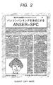
- Fig. 19 is a diagram showing a sample wherein green symbols are written on a white background.
- a binary result 1901 is obtained for a comparatively thick symbol, and the multi-valued image of a black portion in the binary result 1901 has a level change 1902.
- the level change 1902 since the level remains steady for a long time at portions 1903 and 1904, which correspond to the representative color of the symbol, the color is distributed in the color space RGB as is shown in Fig. 20A .
- a block 2002 in Fig. 20A is the color green in Fig. 19 , i.e., indicates the representative color of the symbol. Since the block 2002, of the symbol portion, has a specific size, it can be extracted comparatively easily.
- the level change in a multi-valued image has a shape 1907, and as soon as the level reaches portions 1908 and 1909, which correspond to the representative color of the symbol, it is changed to the level of the background portion.
- the color distribution in the RGB color space is as is shown in Fig. 20B , and compared with the block 2002 in Fig. 20A , using the obtained data it is difficult to calculate a point 2005 in Fig. 20B .
- the left side of a broken line is binarized as a black symbol, and when the representative color is calculated using the conventional method, the point 2005 is obtained as a value, the greatest number that is present. This is not preferable because compared with the desired symbol color, the obtained symbol has a whitish-green cast.
- a green symbol "o" is drawn on a white background.
- the level shift for the symbol "o” has a change 2104. Originally it would be ideal for the center indentation to be returned to the white level; however, the complete return to the white level of the symbol "o", a small point, may not be possible.
- a threshold value 2105 a solid black dot 2102 is obtained as the binary result. And if the thinning process is then performed for this dot 2102, a black dot 2103 is obtained.
- the position of the multi-valued image indicated by this binary image is a point 2106, which is not a preferable level for the representative color.
- the binary image that is the output employed for representing a symbol is used to calculate the representative color for the symbol.
- a threshold value for optimally representing a symbol be binarized, so that no blurring of the symbol occurs. It is further known that, while taking the succeeding OCR process into account, it is better for a binarized symbol to become solid than it is for it to become blurred, since better OCR results can be obtained.
- Fig. 22 is a graph showing a typical histogram for the brightness of a symbol area.
- a point 2201 is a desirable point for a binary image. However, when binarization is performed at this point 2201, a pixel that is shifted from the background to the symbol portion is binarized as a black dot, a preferable output, while when the calculation of the representative color of the symbol is performed, this output constitutes noise.
- United States Patent Specification No. 5778092 discloses a technique for compressing a color or gray scale pixel map representing a document.
- the pixel map is decomposed into a three-plane representation, the foreground plane containing the color or gray scale information of foreground items such as text.
- a background plane contains color or gray scale information for the background and continuous tone pictures.
- the third plane stores information for selecting from either the foreground or the background plane.
- EP-A-0731599 discloses an image processing apparatus in which an appropriate binarization threshold can automatically be set between object density and the background density in a multi-level input image by determining the frequencies of the luminance levels of the entire image and then calculating the average and deviation of the frequencies.
- an image processing apparatus as set out in claim 1 and a method of processing image data as set out in claim 6.
- symbol contains character, and so on.
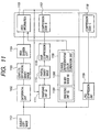
- Fig. 1 is a diagram showing the configuration of an image processing apparatus according to this embodiment.
- a binarizing unit (a) 102 binarizes an input original image 101, and generates a binary image (a) 103.
- An area division unit 104 detects a symbol area or a photograph area in the received binary image (a) 103, and generates the coordinates of the area and an attribute, such as area information 105, for example, for a symbol or a photograph.
- an MMR compression unit 106 Based on the area information 105, an MMR compression unit 106 performs MMR compression for a part of the binary image (a) 103 that corresponds to the area having a symbol attribute, and generates compressed code D 107.
- a symbol representative color operation unit 108 calculates the representative color of a symbol that is included in the area that corresponds to the area having the symbol attribute.
- a binarizing unit (b) 1081, for calculating the symbol representative color, is included in the symbol representative color operation unit 108 and generates a binary image (b) 1082. The color information obtained during this process is newly written as the attribute of the area information 105.
- a JPEG compression unit 109 compresses a part of the original image, which is included in the area corresponding to the area including the attribute of a natural image, and generates compressed code C 110.
- Fig. 3 is a flowchart showing the processing performed by the binarizing unit (a) 102 and the area division unit 104.
- Steps S301 to S303 show the processing performed by the binarizing unit (a) 102, and steps S304 to S306 show the processing performed by the area division unit 104.
- an original image 101 such as an RGB color image
- the brightness conversion for this image is performed by using the following equation to generate a brightness image J.
- Y 0.299 ⁇ R + 0.587 ⁇ G + 0.114 ⁇ B .
- step S302 the brightness data histogram is prepared, and the threshold value T used for binarization is calculated.
- the brightness image J is binarized by using the threshold value T, and a binary image K is generated.
- step S304 the borderline of a black pixel is traced, and a label attachment is performed for each of the black areas.
- step S305 the forms and positions of the black areas to which the labels are attached are employed to determine whether the image is a symbol or a natural image.
- the symbol areas are combined in accordance with their forms and positions, although the combining process at step S306 need not always be performed. In this case, the number of symbol areas for which the representative color is calculated is increased and the processing time is extended, while the advantage is that a change in a color can be coped with accurately.
- Fig. 6 is a diagram showing the state wherein the border line tracing is performed for the binary image in Fig. 5 at a reduced resolution, and label attachment is performed for all the black areas (S304). The form and position information of the black areas to which the labels are attached is employed to determine the attribute of a symbol or a natural image (S305).
- this image is not actually generated but is merely a concept.
- a portion 601 is large and contains a black area, it is determined to be a natural image.
- areas 602 to 605 include symbols and have empty shapes, their areas are determined to be frames.
- frame information is not included as area information 105, and is ignored.
- an application may hold the frame information, or may employ the frame information as the background for the symbol area information. In this case, means for calculating the color of the background must be provided.
- Fig. 7 is a diagram showing a black area wherein the symbol attribute is extracted from the original image in Fig. 2 .
- grouping S306 is performed, and the 17 coordinate data sets, for which the symbol attribute applies, are stored in the JPEG compression unit 109 in Fig. 1 , while the coordinate data 601 in Fig. 6 , for which a photograph attribute applies, are stored in the JPEG compression unit 109 in Fig. 1 .
- Fig. 9 is a flowchart showing the processing performed by the symbol representative color operation unit 108. Since this processing is performed for all the coordinates included in the area information 105, at step S901 a check is performed to determine whether there is are symbol coordinates that have not been processed. If it is determined there are symbol coordinates that have not been processed, program control advances to step S902, or if it is determined there are no such coordinates, the processing is terminated.
- step S902 a check is performed to determine whether a symbol attribute applies to the coordinates; if one does, program control advances to step S903, whereas if one does not, program control returns to step S901.
- a brightness histogram is calculated for the original image corresponding to the area information. Since this histogram is for a partial symbol area, it is highly probable that it does not have a complicated shape comparable to that of the inclusive histogram shown in Fig. 4 , but has a simple shape such as the one shown in Fig. 22 .
- step S904 calculations are performed to obtain an optimal threshold value, i.e., a threshold value T2 according to which the blurring of a symbol occurs, to be used for determining a representative color.
- This threshold value T2 corresponds to the point 2202 in Fig. 22 .
- a value of 0 is substituted into a variable "limit" for counting the number of procedures, so that the processing does not enter an endless loop.
- the brightness histogram is used for calculations performed to obtain an average value for the histogram and its skew, which is specially stored as skew_first.
- step S1003 "average” is substituted into HistUpper, and a value of 0 is substituted into HistLower, following which, at step S1004, a check is performed to determine whether a variable "limit” is equal to or greater than 10.
- program control is shifted to step S1009 (in this case, instead of 10, 5 or 20 may be employed).
- step S1005 HistUpper is used to calculate the histogram for HistLower.
- step S1006 a check is performed to determine whether the condition skew ⁇ my*0.1 is satisfied, and when it is, no further calculations are required and program control jumps to step S1010.
- program control advances to step S1007 whereat a check is performed to determine whether the conditions skew ⁇ 0.0 and skew_first ⁇ skew*0.1 are satisfied. If these conditions are satisfied, no further calculations are required and program control jumps to step S1010. But if these conditions are not satisfied, program control advances to step S1008 and "average" is substituted into "HistLower". Subsequently, at step S1009, the variable "limit” is incremented by one and program control returns to step S1004.
- the threshold value according to which no black pixels are present when the image is binarized, could be obtained depending on the shape of a histogram, the number of pixels nearer the black area from the threshold value T2 is counted. When the number of pixels is extremely small, the pixels need to be more or less corrected so they are closer to being white. The shape of the histogram that tends to echo such results is shown in Fig. 17 .
- Fig. 18 is a diagram showing a threshold value calculation example.
- the binarizing unit (b) 1081 binarizes a partial area using the threshold value T2, and generates the binary image (b) 1082 in Fig. 1 .
- the area is binarized by using the threshold value T2, i.e., the point 2202, and this means that the area is binarized at the level 2401 in Fig. 24 , so that the binarization can be performed without including the shifting portions 2402 and 2403. Then, as needed, the thinning process is performed for the obtained binary image.
- a histogram is generated for each RGB pixel of the original image that corresponds to the black portions of the binary image (b).
- the color space for the histogram may not only be RGB, but may also be YUV when the original image is YUV.
- each of the peaks of the RGB histograms are defined as symbol representative colors, and are written in the area information 105 as the attributes of corresponding areas.
- steps S906 and S907. instead of the histogram for each RGB pixel, a RGB three-dimensional histogram is calculated. In this case, it is impossible for the function of a calculator to calculate a histogram in detail, and it is preferable that a rough histogram be calculated in order that it will not be affected by the noise produced by a color shift point. As one method, first a highest value is obtained by using the rough histogram, then a detailed histogram present in the rough histogram is calculated, and finally the highest value is obtained again.
- MMR compression is performed for the area for which the symbol attribute applies and that corresponds to the binary image (a) 102, and the compressed code D 107 is generated.
- JPEG compression is performed for the area for which the natural image attribute applies and that corresponds to the original image data, and compressed code C 110 is generated.
- a format is generated by collecting the area information 105 that includes the area type, such as a symbol or a natural image, and the representative color when the image is a symbol, as well as the compressed code C 111 and the compressed code D 112. The obtained format is used as compressed data.
- Fig. 11 is a diagram showing the configuration of an image processing apparatus according to a second embodiment of the present invention.
- a binary image obtained by using a threshold value is not employed as an image for which area division is performed. Instead, an edge amount relative to an adjacent pixel is calculated for all the pixels through differential filtering, and is binarized to obtain a binary image, and this binary image is used to perform area division. Border line tracing as used in the first embodiment is also used as an area division method.
- an area that is to be extracted as a symbol also includes an area that would be inverted by normal binarization.
- Fig. 12 is a diagram showing the difference between normal symbols and inverted symbols.
- An inverted symbol is, for example, a white symbol on a red background, not particularly a rarity in a color document.
- a symbol attribute is not provided for an inverted symbol, and a natural nature attribute is provided for an area that includes an outer colored frame.
- an inverted symbol area as shown in Fig. 12 , can also be divided into symbols.
- the brightness histogram has the shape shown in Fig. 13
- normally a symbol area histogram has the shape shown in Fig. 22 .
- a crest portion 1301 indicates a block of the background, and a crest portion 1302 indicates a block of symbols.
- the inversion process is required for a binarization process for generating a partial binary image (b) (11082 in Fig. 11 ) used to calculate the symbol representative color.
- a determination as to whether a symbol is to be inverted can be made using the following equation.
- a DoInvert flag which instructs the binarization unit to perform an inversion process, is set.
- a binarizing unit (b) 11081 and a binarizing unit (a) 1111 which outputs the visual results, invert the binarization results.
- an area division unit 1104 In the arrangement provided to cope with an inverted symbol, an area division unit 1104 must detect an area having a frame attribute, and the average color in the frame must also be calculated. This is because the background color of the inverted symbol is other than white, and this color must be represented. The frame area average color operation unit in charge of this process is not shown in Fig. 11 .
- FIG. 14 The configuration of an image processing apparatus shown in Fig. 14 may also be employed.
- a symbol area extraction unit 1402 for detecting only the coordinates of a symbol area is provided for the area division process, and stores a symbol area coordinate 1403.
- a binarizing unit 1404 generates a binary image 1405 of a symbol area, and in accordance with the binary image 1405, a symbol portion painting unit 1408 generates a document 1413 wherein the symbol portion of the original image is painted the average color of the surrounding portion.
- MMR compression is performed for the obtained partial binary image, and compressed code D is generated, while JPEG compression is performed for the symbol omission image and compressed code C is generated.
- a symbol representative color operation unit 1411 performs the processing shown in Fig. 9 for the first embodiment, and generates a representative color 1412.
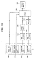
- Fig. 15 is a diagram showing the configuration for expanding compressed data obtained by the arrangement in Fig. 14 .
- a JPEG expansion process is performed for the compressed data C, and a multi-valued image G is generated. Further, the MMR expansion process is performed for the compressed code D, and a binary image F is generated for the partial area. Then, a combining process is performed in which the representative value is added to the black binary pixels in the image G while the binary white image is unchanged, and finally, an image H is obtained.
- the present invention may be employed for a system that is constituted by multiple apparatuses (e.g., a host computer, an interface device, a reader or a printer), or for a single apparatus (e.g., a copier or a facsimile machine).
- apparatuses e.g., a host computer, an interface device, a reader or a printer
- a single apparatus e.g., a copier or a facsimile machine.
- the objective of the invention can also be achieved by supplying, to a system or an apparatus (or a CPU or an MPU), a storage medium (or a recording medium) on which software program code that implements the functions of the embodiments is recorded, and by permitting the system or the apparatus to read and execute the recorded program code.
- the program code read from the storage medium provides the functions of the above described embodiments
- the storage medium on which the program code is recorded constitutes the present invention.
- the program code can interact with an Operating System (OS) running on a computer, or with another software application, to provide the functions described in the above embodiments.
- OS Operating System
- program code read from a storage medium, can be written in a memory that is mounted on a function expansion board inserted into a computer, or in a function expansion unit connected to the computer, and in consonance with instructions in the program code, a CPU mounted on the function expansion board, or in the function expansion unit, can perform part or all of the actual processing required to implement the functions of the above described embodiments.
- a histogram consonant with an input image is calculated, and is employed to calculate the binary threshold value according to which a predetermined area in an image is blurred.
- the input image is binarized by using the obtained binary threshold value, and is employed to calculate the color of the predetermined area of the input image. Therefore, even for a thin line symbol, the color data of the portion that is shifted from the background to the symbol can be deleted, so that an optimal representative color can be obtained for the symbol.
- the image processing apparatus of this embodiment first generates a brightness histogram for the entire image area, binarizes the image area, and extracts several symbol areas. Then, a symbol cutting process is performed for the individual symbol areas, and the results are employed to determine whether each obtained area should be treated again as a symbol area. When the area should not be treated as a symbol area, a check is performed to determine whether an object in the pertinent area has a single color. When the object has a single color, it is ascertained that MMR compression should be performed for this object. When the object does not have a single color, it is ascertained that JPEG compression should be preformed for the object.
- the colors constituting the area are reduced through a predetermined color reduction process.
- the image can be represented by a predetermined number (e.g., four) of colors or less, each time the symbol cutting process is performed, palettes representing the individual colors and multi-valued images indicating the pixel positions of the colors are correlated with each other to be determined as ZIP compression targets.
- the image can not be represented by the predetermined number of colors, the original image before the color reduction process is performed is determined to be the JPEG compression target.
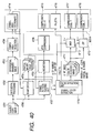
- Fig. 25 is a diagram showing the configuration used when the present invention is employed for the image compression method.
- An image binarizing unit 3102 receives an original image 3101, and optimally binarizes the original image 3101 to obtain a whole surface binarized image 3103.
- a symbol area detector 3104 receives the complete surface binarized image 3103, detects a symbol area, and prepares symbol area coordinates 3112.
- a symbol color extraction unit 3108 receives the symbol area coordinates 3112, refers to the original image at the coordinates and the binary image 3103 to calculate the original image color in the black portion of the binary image, prepares multiple palettes 3114, and performs the color reduction process for the original image in accordance with the palettes 3114.
- a symbol portion painting unit 3105 extracts, from the original image, the black portion of the binary image 3103 in an area that is determined to be a symbol by the symbol area detector 3104 and for which the symbol color extraction unit 3108 reduces the number of symbol colors to less than M, paints the black portion the color of the surrounding portion, and prepares an image A.
- a reduction unit 3106 receives and reduces the image A, and generates an image B.
- a JPEG compression unit 3107 receives the image B, and performs JPEG compression for the image B to generate compressed code X (3113).
- a color reduced image 3109 is for multiple symbol areas the colors of which are reduced by the symbol color extraction unit 3108.
- an MMR compression unit 3110 receives the color reduced image 3109 and performs MMR compression to obtain multiple compressed codes Y (3115).
- a ZIP compression unit 3111 receives this image 3109 and compresses it to obtain multiple compressed codes Z (3116). Finally, the data 3112 to 3116 are combined to obtain compressed data 3001A.
- Fig. 27 is a flowchart for explaining the processing performed by the symbol area detector 3104.
- a color image is received and brightness conversion is performed for the color image, while the resolution is reduced by thinning and a brightness image J is obtained.
- the original image is, for example, RGB 24 bites at 300 dpi
- the new image J that is obtained is Y8 bits at 75 dpi.
- the histogram for the brightness data is prepared, and the binary threshold value T is calculated.
- the brightness image J is binarized by using the threshold value T, and a binary image K is created. Further, at step S3304, border line tracing is performed for the black pixels, and label attachment is performed for all the black areas. At step S3305, areas that are assumed to be symbols are determined in the black area, and at step S3306 the areas are combined in accordance with their shapes and positions.
- a color document in Fig. 4 is received, and a histogram in Fig. 5 is obtained by thinning and performing brightness conversion for the color document.
- the average data and distribution data are employed to calculate the threshold value T (e.g., 150), and a binary image shown in Fig. 6 is obtained.
- T e.g. 150
- a binary image shown in Fig. 6 is obtained.
- the border line tracing is performed for the black pixels in Fig. 6 , and through label attachment, only a group of black pixels, the width or the height of which is equal to or smaller than the threshold value, is identified as a symbol.
- the group of black pixels in Fig. 7 is determined to be a symbol area.
- the image is shown purely for the sake of the explanation and it is not actually created during the symbol area detection process.
- an edge amount relative to an adjacent pixel may be calculated for all the pixels and binarized, and border line tracing may be performed for the obtained binary image to detect a symbol area.
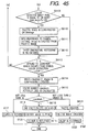
- Fig. 43 is a flowchart for the processing performed by the symbol color extraction unit 3108.
- the complete surface binarized image 103 is employed in this processing; however, only the coordinates of a symbol area and a color image may be received, and the image obtained by binarizing the color image may be employed to perform the representative color operation process.
- the processing in Fig. 43 is performed for all the areas that the symbol area detector 3104 determines to be symbol areas.
- the re-binarization judgement is performed at step S6001.
- the complete surface binarized image 3103 is not always the image obtained by preferably binarizing all the symbol areas. Since the quality of the resultant image is adversely affected, regardless of whether the binary image is too thick or too thin, it is ideal for the optimal binarization to be performed for each symbol area. Since, compared with the complete surface histogram in Fig. 29 , a simpler shape shown in Fig. 33 can be expected for the brightness histogram for each symbol area, the threshold value can be easily determined.
- a portion 3901 is a set of background colors, and a portion 3902 is a set of symbol colors. In this embodiment, in order to reduce the processing time, the re-binarization is performed only for a "too thick binary image" that has a greater effect on the image quality.
- the symbol area detector 3104 scans the binary image in the area that is determined to be a symbol, and performs pattern matching with an isolated point filter. A check is performed to determine whether the isolated point that is present is equal to or above the threshold value in the area. When the isolated point is equal to or above the threshold value, the brightness histogram for the area is obtained, the optimal threshold value is calculated, and the re-binarization is performed. For a normal symbol area, the brightness histogram need only be partially prepared to obtain a better image; however, in some cases, worse results may be obtained (the image obtained by re-organization may be worse).
- the binarized threshold value that is used to obtain the complete surface binary image is entered for the re-binarization, and an exception process is provided in which the re-binarization is not performed when a binary image is obtained that has a greater density than the threshold value for the re-binarization.
- step S6002 the symbol cutting information is prepared.
- the symbol cutting unit changes the process depending on whether the symbol area is a landscape or a portrait view.
- the symbol area detector determines the landscape or portrait positioning of the symbol portion in accordance with the arrangement of the black blocks, and prepares information indicating whether landscape or portrait positioning is used.
- landscape positioning is used for the symbol area, first, the black pixels of the binary image are projected in the main scanning direction. And when the separation between lines is detected, the black pixels are projected for each line in the sub-scanning direction, and the information for each symbol is obtained.
- the portrait positioning is used for the symbol area, the line cutting is performed in the sub-scanning direction, and the symbol cutting is performed in the main scanning direction. At this time, it is better for the line cutting to be projected to three segments in the line direction in order to allow the image to be tilted. Through this processing, the coordinate information for each line and the coordinate information for the symbols that are spaced along each line can be obtained.
- the symbol cutting information is employed to determine whether each of black object, in an area that the symbol area detector determines to be a symbol, is a symbol. Specifically, whether the black object is a symbol is determined in accordance with its size and shape. While taking image quality and data compression into account, it is not necessarily required that the black object be a symbol in order to convert it into a single color or a multiple color area (for example, because of a higher image quality and a better compression rate can be obtained, a mark having a single color should be represented by single color MMR rather than the JPEG). However, since it is highly probable that areas other than the symbol area will be represented by gradation, the determination of the object is required.
- the symbol judgement process is performed at step S6003.
- the symbol cutting information (S6002) is entered, and the average symbol size is calculated for each line.
- the object rectangle is extremely larger than the average size, it is determined not to be a symbol, and if the shape of the object does not seem from the aspect ratio to be a symbol in spite of its being of average size, it is also determined not to be a symbol.
- the symbol judgement unit When m black objects are present in the area, and when all the m black objects are determined not to be symbols, the symbol judgement unit outputs a determination that the area is an image.
- n black objects (m > n, n ⁇ 0) among m black objects are not symbols, i.e., when rectangles that do not indicate symbols remain, a black object on the binary image that is determined not to be a symbol is deleted, and a determination that the pertinent area is a symbol is output.
- step S6004 When an area is determined to be a symbol during the symbol judgement process, program control advances to step S6004. And when the area is determined not to be a symbol, program control is shifted to step S6005.
- the monochrome judgement process is performed at step S6005.
- An area to be processed here is an area that is determined by the symbol area detector to be a symbol, but is determined not to be a symbol during the symbol judgement process. As is described above, regardless of whether the area is a symbol, it is better that the monochrome process is performed for the area represented by a single color and that MMR compression be performed for the results, so that a higher image quality and a higher compression ratio are obtained. Thus, a process is performed to determine whether the area is or is not monochrome.
- histograms are obtained for the RGB levels of the pixels of a color image that correspond to black portions of the binary image, and when all the distribution values of the histograms are equal to or greater than the threshold value, it is ascertained that the area is monochrome.
- program control advances to step S6006 for a one color extraction, and when the area is represented by multiple colors, the processing is terminated.
- step S4201 thinning process of a binary image is performed and new binary image newbi is created
- the thinning process is performed for a binary image newbi that is referred to by symbol coordinates, while the number of black objects in a portion wherein the color is shifted from the background to a symbol portion during scanning is reduced, and a new binary image is created.
- the histogram is obtained for the RGB values of the original image that corresponds to the black pixels of the image newbi (the histogram for another color space, such as a YUV space, may be prepared).
- the representative values for RGB are obtained, and in this case, the greatest values may be employed. Or, another method may be employed whereby the greatest value is obtained by using a rough histogram that is prepared using a reduced number of steps, and detailed histograms that are present in the rough histogram are employed to obtain the greatest value.
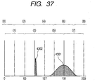
- a true representative value 4301 can be obtained from the histogram shown in Fig. 37 without it being disturbed by noise 4302.
- a detailed explanation will be given while referring to Fig. 37 .
- a detailed histogram of 256 levels in Fig. 37 can be obtained, for example, from R data of eight bits. Since the maximum value is 1302, which is not a true representative value, the histogram is divided by 64 into eight segments that overlap each other, and the eight segments are re-calculated using the histogram for the 256 levels. The obtained segments 0 to 8 are shown; however, segments 0 and 8 each have only 32 levels. It is found through recalculation that a representative value is present in segment 6, and segment 6 is searched to obtain the maximum value 4301. The above processing is repeated for all the symbol coordinates, and one representative color is calculated for each of the symbol coordinates.
- step S6004 the color reduction process is performed for the symbol.
- the color reduction unit 4082 In the processing performed by the color reduction unit 4082, even when the original document is represented by a single color, the portion wherein the color is shifted from the background to the symbol portion is present during the scanning.
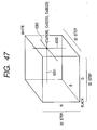
- Figs. 46 and 49 are diagrams showing the color shifting caused by scanning.
- FIG. 49 is a diagram showing the state wherein the color is shifted by using the three-dimensional histogram of the pixel level of the symbol A in Fig. 46 .
- the background color is white 6501
- the symbol color is black 6502
- a portion 5603 is the shifting portion.
- the shifting portion that constitutes a variance due to the scanning of the symbol portion that is originally represented by a single color.
- the shifting portion can be represented using only the representative color, a high image quality is obtained, and the amount of data required is reduced.
- the symbol cutting information is employed to limit the colors to one per symbol, so that the improvement of the image quality and the compression rate is the objective.
- the thinning process is performed for a binary image that is referred to by the symbol coordinates, and the number of black portions that correspond to the shifting portions whereat the color is shifted from the background to the symbol portion during scanning is reduced, and a new image "thinimage" is prepared. Since the binary image "thinimage” is used for the process at step S6110, this image is constituted by eight bytes having binary values of 255 (black) and 0 (white).
- the three-dimensional histogram is obtained for the RGB colors of the original image that corresponds to the black pixel of "thinimage". At this time, when, for example, the input image has RGB colors of eight bits each, a 256*256*256 histogram is normally required.
- the histograms at many such levels is not actually required. Therefore, in this example, a RGB three-dimensional histogram of the upper five bits is obtained. To obtain the histogram, the total number blacknum of black pixels that are present in the symbol area is also calculated.
- the RGB space is employed; however, another color space such as Lab or YUV may also be employed.
- another color space such as Lab or YUV may also be employed.
- a three-dimensional histogram is employed; however, three one-dimensional histograms may be employed for the individual colors.
- the initial process is performed in which the number colnum of the symbol colors that are represented in the area is reset, or in which the number okpixel of the processed pixels is reset.
- the representative value is calculated.
- the point whereat the total value of the seven histograms, including the target histogram, reaches the maximum value is employed as a representative value (seven histograms: a target point, two adjacent points in the R dimension, two adjacent points in the G dimension and two adjacent points in the B dimension (see Fig. 39 )).
- the thus obtained maximum value is substituted into color[colnum], colG[colnum], and colB[colnum].
- the range, with the representative value as the center, of the color to be converted into the representative value is determined.
- Fig. 47 is a diagram showing the three one-dimensional histograms that are obtained.
- the representative value is (Color(26), ColG(30), ColB(22)
- the R one-dimensional histogram has the shape shown in Fig. 48 , and points 6401 and 6402 are detected therefrom, and the "R range" is defined wherein these points are used as the representative values.
- the method for determining a binarized threshold value for an image is employed for the detection of the points 6401 and 6402. While, for example, a point 6403 is a representative value, the histogram including 0 to the representative value is substituted into the binarized threshold value determination function to obtain the point 6401, and the inverted histogram of the histogram including the representative value at step S31 in Fig. 48 is substituted into the binarized threshold value function to obtain the point 6402.
- the color range is determined for R, G and B, and is substituted into fg_range[colnum].
- step 6106 all the values of the three dimensional histogram in fg_range[colnum] are set to 0. At this time, the number of pixels that are set to 0 is added to the okpixel that represents the number of processed pixels.
- step S6107 the approximation color judgement is performed. This process is performed for all the colors (from fg_color[0] to fg_color[colnum ⁇ 1]) that have appeared.
- the processing loop is exited.
- the gradient color occurs between the background color and the symbol color.
- a color pixel (6503) is present between the background color (6501) and the symbol color (6502).
- the color from the line 6504 that is nearer the background color is not added to the three-dimensional histogram (the line 6504 is positioned nearer the symbol color side by thinning the binary image).
- the gradient portion is still present, and the color of this portion would be extracted after the symbol color 6502 has been extracted.
- fg_color[0] is (32, 40, 40)
- (96, 112, 96) tends to be extracted for fg_color[m].
- the background color should also be detected, and the color that is present along the extended line from the background color and fg_color[0] should be determined to be the approximation color.
- the pertinent color is determined to be the approximation color.
- the determination result is maintained in the kinji[] matrix.
- the colors having the same numbers in kinji[] represent the approximation color.
- kinji[0] and kinji[3] are both 0. That is, fg_color[0] and fg_color[3] are determined to be approximation colors.
- fg_color[1] (248, 64, 48)
- kinji[1] 1
- fg_color[2] (48, 256, 32)
- kinji[2] 2
- step S6019 a check is performed to determine whether the number of black pixels for which color extraction has been completed has exceeded 75% ("75" is merely an example).
- program control advances to step S6110. If the number of black pixels has not exceeded 75%, program control is shifted to step S6113.
- a palette image is formed in the "thinimage".
- the pixel RGB level of the color image wherein the value of the "thinimage” corresponds to pixel 255 (indicating color allocation has not yet been performed) is referred to, and when the RGB data is present in fg_range[m], the value of kinji[m]+1 (i.e., a value of 1) is substituted into the pixel value that "thinimage" corresponds to.
- kinji[m]+1 is substituted because since a value of 0 is a special number representing a non-symbol portion (background portion), when kinji[m] is 0 it can not be substituted.
- step S6110 When, at step S6110, the palette image is formed in "thinimage", at step S6111 color information charpal for each symbol is prepared from the palette image by using the symbol cutting information.
- the color allocated to each symbol cut potion is selected from among three charpals, 0 to 2.
- re-acquisition of the three-dimensional histogram at step S6112 may be performed only one time, and the processes at step S6110 and S6111 may be limited to two repetitions. Experiments have shown that is enough to obtain a satisfactory image quality.
- step S6114 when program control exits the loop at step S6113, there could still be a symbol for which charpal has not been processed. Therefore, when the number of symbols nokorichar for which charpal has not been processed is equal to or greater than one, at step S6114, the color information is forcibly allocated to the unprocessed charpal. Specifically, in the allocation process at step S6111, only when the maximum value is obtained is the color information substituted into charpal, while taking into account the succeeding trend of the pixel 255 of "thinimage" (i.e., the pixel for which color extraction has not yet been performed).
- step S6114 the pixel 255 of "thinimage" is ignored, and the maximum value among the pixels other than 0 (background) is used to determine the value for charpal. Since is a case exists wherein the pixels other than 0 (background) are all 255 (color extraction is not performed even for one pixel), the color of charpal for a symbol positioned nearby is substituted into charpal. For example, when “ “ in Fig. 50 corresponds to the conditions in this case, charpal of the nearby positioned " " is substituted in.
- the numerical value "colnum” is obtained as the number of colors that have been extracted. However, since this value includes the approximation color and also may include a color that is not used, even though it was extracted, the value colnum differs from the number of colors actually used (usecolnum). Thus, at step S6115, the charpal is examined to calculate the number of colors that are actually used.
- step S6116 When, at step S6116, "usecolnum" calculated at step S6115 is equal to or greater than 16, 17 colors including the background (0) are present and can not be represented by four bits. Thus, program control advances to step S6117, the color reduction process for this area is abandoned, and DOJPEG is returned (the area is represented as the background image). It should be noted that when the use of eight bits rather than four bits is permitted, the usecolnum is not 16 but 256.
- step S6118 When usecolnum is one, program control is shifted to step S6118, and a palette of one color is prepared for use. At step S6119, the input binary image is clipped, and at step S6120 DOMMR is returned.
- step S6121 When usecolnum is equal to or greater than two and smaller than 16, program control is shifted to step S6121, the palette of colors to be used is prepared, and at step S6122, a palette image is created.
- a palette represented as using two bits for each pixel is created, while when the usecolnum is equal to or greater than four and smaller than 16, a palette represented as using four bits for each pixel is created.
- DOZIP is returned.
- the MMR compression unit 3110 When the thus obtained color reduced image 3109 has one bit (DOMMR is returned as the result of symbol color extraction), the MMR compression unit 3110 performs MMR compression for the image 3109 and prepares the compressed code Y. When the color reduced image 3109 has two or more bits (DOZIP is returned as the result of symbol color extraction), the ZIP compression unit 3111 compresses the image 3109 and prepares the compressed code Z. When DOJPEG is returned, the image 3109 is not transmitted to the MMR compression unit 3110 or the ZIP compression unit 3111, whereat the reduced color image is not present, and a command is transmitted to the symbol portion painting unit 3105 so as not to treat the image as a symbol area.
- Fig. 35 is a flowchart showing the symbol portion painting processing.
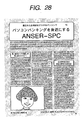
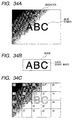
- Fig. 34A wherein a gradation image is used as a background and blue symbols ABC are drawn substantially in the center
- Fig. 34B the binary image of one symbol area shown in Fig. 34B is obtained from the original image.
- the entire image is divided into 32 ⁇ 32 areas (hereinafter referred to as parts), and the process is performed for each part.
- the state obtained during this process is shown in Fig. 34C .
- 5 x 5 parts are shown, and the numbers in the upper left portions of the parts indicate the part numbers.
- the number of parts is not limited to the number used here, and an image may be divided into a different number of parts.
- a check is performed to determine whether a part has not been processed.
- a check is performed to determine whether the target area for the symbol portion painting is present in that part.
- An area for which the symbol color extraction unit 3108 has returned the DOJPEG is not regarded as a symbol portion painting target, even though that area is determined by the symbol area detector 3104 to be a symbol area.
- step S4103 it is ascertained at step S4103 that there are no symbol portion painting target areas in parts 00 to 04, 10, 14, 20, 24 and 30 to 35, and without performing any process for them, the next part is processed.
- the part e.g., part 1 wherein a symbol portion painting target area is present
- step S4104 by referring to a corresponding binary image, the average value ave_color is calculated for the RGB values (or YUV values) of the color image that corresponds to the white portion of the binary image.
- step S4105 the corresponding binary image is referred to, and the pixel density data for corresponding black pixels are determined to be ave_color.
- the above described processing is repeated for parts (parts 12, 13, 21, 22 and 23) wherein symbol painting target areas are present.
- the average value of peripheral pixels can be embedded in the portions wherein the symbol is present.
- the obtained image is reduced by the reduction unit 3106.
- a simple thinning-out process is employed for size reduction.
- the reduction process and the symbol portion painting process may invertedly be performed. In this case, position shifting between the binary image and the color image must be taken into account.
- a format is prepared by collecting the symbol area coordinates 3112, the palette 3114, the compressed code X 3113, the compressed code Y 3115 and the compressed code Z 3116.
- An example format for collecting these five is the PDF of Adobe (trademark).
- the PDF of Adobe is a format that is displayed by the application "Acrobat Reader (trademark)", which is distributed by Adobe for free, and a problem such as one where a reception side that does not have an application to prepare a document, and thus can not open a file, can be avoided.
- Another example format is XML.
- XML is a descriptive language used for the exchange or distribution of documents or data via a network.
- Fig. 26 is a diagram showing the arrangement required for the expansion process.
- a JPEG expansion unit 3201 performs JPEG explanation for the received compressed code X 3113, and prepares a multi-valued image E.
- An enlargement unit 3202 receives the multi-valued image E, and enlarges it to obtain a multi-valued image F 3203.
- An MMR expansion unit 3204 receives the compressed code Y 3115, and prepares a binary image G 3205.
- An IP expansion unit 3206 receives the compressed code Z 3116, and creates a multi-color image H 3207.
- an image combining unit 3208 receives the symbol area coordinates 3112, and corresponding palette 3114 and binary image G 3205 or multi-color image H 3207; selects the color of the pixel of the image F 3203 when the image data of the binary image or the multi-color image represents transparency, or selects a corresponding palette color in the other case; and creates a final image I 3209.
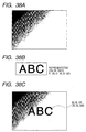
- Figs. 38A to 38C are diagrams showing the results obtained by the combining unit 3208.
- the compressed code C obtained by JPEG expansion is shown in Fig. 38A .
- the image in Fig. 34 is employed; however, when the quantization irreversible method for JPEG compression is employed, data are obtained whose pixel value slightly differs from that in Fig. 34C .
- a change in the pixel value is small when the same quantization table is employed. In other words, a high quality image is obtained.
- the binary image obtained by MMR compression is used as the symbol area for which the combining process is to be performed.
- the binary image obtained by the expansion is shown in Fig. 38B .
- the palette color (20, 30, 255) data are placed on the image portions in Fig. 38A that correspond to black pixels, and finally, the image shown in Fig. 38C is obtained.
- the number of palettes is changed. For example, for two bits, the palettes allocated for four pixel values 00, 01, 10 and 11 are applied. One of the pixels represents transparency, and when, for example, it is 00, the pixel in Fig. 38A is selected for this pixel.
- the palette value of 01 is applied; for the pixel value of 10, the palette value of 10 is applied; and for the pixel value of 11, the palette value of 11 is placed.
- the expanded image 3209 is obtained.
- the binary image is created by using the complete surface single threshold value.
- another threshold value may be employed; for example, an optimal threshold value may be calculated for each symbol area detected by the symbol area detector 3104, and a binary image may be created.
- the re-binarization determination process at step S4001 in Fig. 43 is not required.
- the same binary image has been used by the symbol portion painting unit 3105 and the symbol color extraction unit 3108; however, the same binary image need not always be used, and an optimal binarizing unit may be internally provided for the units 3105 and 3108.
- a differential processing unit 4702 performs the differential filtering shown in Figs. 41A and 41B for pixels with a target pixel as the center, and binarizes the pixels in such a manner that, when the absolute value of the pixel value exceeds the threshold value, the pixel is determined to be black, and when the absolute value does not exceed the threshold value, the pixel is determined to be white.
- the primary differential filter is shown in Fig. 41A .
- the horizontal line can be detected by the upper portion, while the vertical line can be detected by the lower portion, and the oblique line can be detected by using the total of the absolute values of two filters. Further, the oblique line filter may also be employed.
- a secondary differential filter that copes with all the directions is shown in Fig. 41B .
- the secondary differential filter can also be prepared for horizontal detection and vertical detection. This filter is positioned for all the pixels, and a differential image 4702 is created. At this time, when the filtering is performed while thinning the pixels, the resolution can be reduced at the same time.
- the process beginning at step S3303 in Fig. 27 is performed for the thus obtained binary image, the coordinates of a symbol area that includes an inverted symbol can also be detected.
- the binarizing unit 4703 To also extract the inverted symbol as a symbol area, the binarizing unit 4703 must cope with this process.
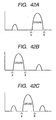
- the inverted symbol area is extracted as a symbol area, mainly the pattern in Fig. 42 is received, while it has been assumed in the above embodiments that only the pattern in Fig. 33 is received.
- the case in Fig. 42B is for the inverted symbol
- the case in Fig. 42C is where symbols of two colors, a black symbol and a white symbol, are present in the same gray background.
- the binarizing unit 4703 need only detect points A and B and perform the binarization process, so that the area sandwiched between the points A and B is white and the other area is black. Or, disregarding the case in Fig.
- the inverted symbol area which remains in the JPEG compressed image in the fourth embodiment, can be smoothed through the symbol potion painting process. As a result, compression efficiency is improved, and the inverted symbol portion can be compressed without a reduction in the resolution or deterioration due to mosquito noise.
- the present invention may be employed for a system that is constituted by multiple apparatuses (e.g., a host computer, an interface device, a reader or a printer), or for one apparatus (e.g., a copier or a facsimile machine).
- apparatuses e.g., a host computer, an interface device, a reader or a printer
- one apparatus e.g., a copier or a facsimile machine.
- the invention can also be carried out by supplying, to a system or an apparatus (or a CPU or an MPU), a storage medium (or a recording medium) on which software program code that implements the functions of the embodiments is recorded, and by permitting the system or the apparatus to read and execute the recorded program code.
- the program code read from the storage medium provides the functions of the above described embodiments
- the storage medium on which the program code is recorded constitutes the present invention.
- the program code can interact with an Operating System (OS) running on a computer, or with another software application, to provide the functions described in the above embodiments.
- OS Operating System
- program code read from a storage medium, can be written in a memory that is mounted on a function expansion board inserted into a computer, or in a function expansion unit connected to the computer, and in consonance with instructions in the program code, a CPU mounted on the function expansion board, or in the function expansion unit, can perform part or all of the actual processing required to implement the functions of the above described embodiments.
- the symbol can be efficiently represented by multiple colors, and when this method is used for the compression system, high quality image compression can be performed at a high compression rate.
Landscapes
- Engineering & Computer Science (AREA)
- Multimedia (AREA)
- Signal Processing (AREA)
- General Physics & Mathematics (AREA)
- Physics & Mathematics (AREA)
- Computer Vision & Pattern Recognition (AREA)
- Theoretical Computer Science (AREA)
- Discrete Mathematics (AREA)
- Artificial Intelligence (AREA)
- Facsimile Image Signal Circuits (AREA)
- Compression Of Band Width Or Redundancy In Fax (AREA)
- Image Processing (AREA)
- Image Analysis (AREA)
- Image Input (AREA)
Claims (11)
- Appareil de traitement d'image comportant :un premier moyen de binarisation (102, S301-S303) destiné à générer une première image binaire (103) en binarisant une image d'entrée basée sur une première valeur de seuil binaire ;un moyen de division par zones (104 ; S304-S306) destiné à détecter une zone de symbole utilisant la première image binaire ;un moyen de calcul d'histogramme (108 ; S903) destiné à calculer un histogramme de luminosité pour l'image d'entrée correspondant à la zone de symbole détectée par ledit moyen de division par zone ;un moyen (108 ; S904) de calcul de valeur de seuil binaire destiné à calculer une seconde valeur de seuil binaire, basée sur ledit histogramme de luminosité, avec laquelle des symboles de la zone de symbole sont floutés ;un second moyen de binarisation (1081 ; S905) destiné à générer une seconde image binaire (1082) en binarisant l'image d'entrée basée sur la seconde valeur de seuil binaire ; etun moyen de calcul (108 ; S906-S907) destiné à calculer des couleurs représentatives de la zone de symbole sur la base de la seconde image binaire et de l'image d'entrée, et à stocker les couleurs représentatives calculées en tant qu'attribut de la zone de symbole correspondante de la première image binaire.
- Appareil selon la revendication 1, dans lequel ledit moyen de calcul est conçu pour calculer les couleurs représentatives de la zone de symbole en utilisant des parties dans ladite image d'entrée qui correspondent à des parties noires de ladite seconde image binaire.
- Appareil selon la revendication 2, dans lequel ledit moyen de calcul est conçu pour calculer les couleurs représentatives de la zone de symbole en utilisant un histogramme à trois dimensions RGB pour les parties dans ladite image d'entrée qui correspondent à des parties noires de ladite seconde image binaire.
- Appareil selon l'une quelconque des revendications précédentes, dans lequel chacun dudit premier moyen de binarisation et dudit second moyen de binarisation comprend en outre un moyen d'inversion destiné à inverser les résultats binarisés.
- Appareil selon l'une quelconque des revendications précédentes, dans lequel ladite première unité de binarisation convertit (S301) l'image d'entrée en une image de luminosité pour calculer (S302) la première valeur de seuil binaire sur la base d'un histogramme de luminosité de l'image de luminosité, et pour générer (S303) la première image binaire en binarisant l'image de luminosité de l'image d'entrée sur la base de la première valeur de seuil binaire.
- Procédé de traitement d'images comprenant les étapes qui consistant :à générer (S301-S303) une première image binaire (103) en binarisant une image d'entrée sur la base d'une première valeur de seuil binaire ;à détecter (S304-S306) une zone de symbole en utilisant la première image binaire ;à calculer (S903) un histogramme de luminosité pour l'image d'entrée correspondant à la zone de symbole détectée par ladite étape de division par zones ;à calculer (S904) une seconde valeur de seuil binaire, basée sur ledit histogramme de luminosité dans lequel des symboles se trouvant dans la zone de symbole sont floutés ;à générer (S905) une seconde image binaire (1082) en binarisant l'image d'entrée sur la base de la seconde valeur de seuil binaire ; età calculer (S906-S907) des couleurs représentatives de la zone de symbole sur la base de la seconde image binaire et de l'image d'entrée, et à stocker les couleurs représentatives calculées en tant qu'attribut de la zone de symbole correspondante de la première image binaire.
- Procédé selon la revendication 6, dans lequel ladite étape de calcul calcule les couleurs représentatives de la zone de symbole en utilisant des parties dans ladite image d'entrée qui correspondent à des parties noires de ladite seconde image binaire.
- Procédé selon la revendication 7, dans lequel ladite étape de calcul calcule les couleurs représentatives de la zone de symbole en utilisant un histogramme à trois dimensions RGB pour les parties dans ladite image d'entrée qui correspondent à des parties noires de ladite seconde image binaire.
- Procédé selon l'une quelconque des revendications 6 à 8, dans lequel chacune desdites première et seconde étapes de binarisation comprend en outre une étape d'inversion consistant à inverser les résultats binarisés.
- Procédé selon l'une quelconque des revendications 6 à 9, dans lequel ladite première étape de binarisation convertit (S301) l'image d'entrée en une image de luminosité, calcule (S302) la première valeur de seuil binaire sur la base d'un histogramme de luminosité de l'image de luminosité et génère (S303) la première image binaire en binarisant l'image de luminosité de l'image d'entrée sur la base de la première valeur de seuil binaire.
- Support lisible par ordinateur portant un code pour amener un ordinateur à exécuter toutes les étapes de l'une quelconque des revendications 6 à 10.
Applications Claiming Priority (4)
| Application Number | Priority Date | Filing Date | Title |
|---|---|---|---|
| JP2000211377A JP4027016B2 (ja) | 2000-07-12 | 2000-07-12 | 画像処理装置、画像処理方法及び記憶媒体 |
| JP2000211377 | 2000-07-12 | ||
| JP2001193640 | 2001-06-26 | ||
| JP2001193640A JP3715905B2 (ja) | 2001-06-26 | 2001-06-26 | 画像処理装置、画像処理方法、プログラム並びに記憶媒体 |
Publications (3)
| Publication Number | Publication Date |
|---|---|
| EP1173003A2 EP1173003A2 (fr) | 2002-01-16 |
| EP1173003A3 EP1173003A3 (fr) | 2004-11-03 |
| EP1173003B1 true EP1173003B1 (fr) | 2009-03-25 |
Family
ID=26595877
Family Applications (1)
| Application Number | Title | Priority Date | Filing Date |
|---|---|---|---|
| EP01305987A Expired - Lifetime EP1173003B1 (fr) | 2000-07-12 | 2001-07-11 | Procédé et appareil de traitement d'images |
Country Status (4)
| Country | Link |
|---|---|
| US (3) | US6999619B2 (fr) |
| EP (1) | EP1173003B1 (fr) |
| CN (2) | CN100348014C (fr) |
| DE (1) | DE60138073D1 (fr) |
Families Citing this family (33)
| Publication number | Priority date | Publication date | Assignee | Title |
|---|---|---|---|---|
| EP1173003B1 (fr) * | 2000-07-12 | 2009-03-25 | Canon Kabushiki Kaisha | Procédé et appareil de traitement d'images |
| JP4139154B2 (ja) * | 2001-08-30 | 2008-08-27 | 株式会社リコー | 画像通信装置 |
| US7283676B2 (en) * | 2001-11-20 | 2007-10-16 | Anoto Ab | Method and device for identifying objects in digital images |
| KR100850705B1 (ko) * | 2002-03-09 | 2008-08-06 | 삼성전자주식회사 | 시공간적 복잡도를 고려한 적응적 동영상 부호화 방법 및그 장치 |
| US20030194127A1 (en) * | 2002-04-10 | 2003-10-16 | Hubel Paul M. | Chromaticity histogram that is weighted for brightness |
| AU2003285891A1 (en) * | 2002-10-15 | 2004-05-04 | Digimarc Corporation | Identification document and related methods |
| JP4047192B2 (ja) * | 2003-02-24 | 2008-02-13 | キヤノン株式会社 | 画像圧縮装置及び方法、画像伸張装置及び方法、プログラム |
| JP2004304469A (ja) * | 2003-03-31 | 2004-10-28 | Minolta Co Ltd | 原稿画像の領域分割・圧縮プログラム及び領域分割・圧縮方法 |
| US7343046B2 (en) * | 2004-02-12 | 2008-03-11 | Xerox Corporation | Systems and methods for organizing image data into regions |
| US7629989B2 (en) * | 2004-04-02 | 2009-12-08 | K-Nfb Reading Technology, Inc. | Reducing processing latency in optical character recognition for portable reading machine |
| KR100648350B1 (ko) * | 2004-11-15 | 2006-11-23 | 엘지전자 주식회사 | 문서영상의 반전 처리 장치 및 반전 처리 방법 |
| KR100752850B1 (ko) * | 2004-12-15 | 2007-08-29 | 엘지전자 주식회사 | 디지털 영상 촬영장치와 방법 |
| CN100372361C (zh) * | 2005-03-16 | 2008-02-27 | 中国科学院沈阳自动化研究所 | 实时浮动阈值提取方法 |
| KR100599141B1 (ko) * | 2005-05-20 | 2006-07-12 | 삼성전자주식회사 | 문서 압축시스템 및 그 압축방법 |
| DE102005033863A1 (de) * | 2005-07-20 | 2007-01-25 | Robert Bosch Gmbh | Bildaufnahmesystem |
| JP2008242733A (ja) * | 2007-03-27 | 2008-10-09 | Seiko Epson Corp | 画像処理装置 |
| JP4894588B2 (ja) * | 2007-03-29 | 2012-03-14 | 富士ゼロックス株式会社 | 画像処理装置、印刷装置及び画像処理プログラム |
| US8326028B2 (en) * | 2007-12-26 | 2012-12-04 | Hitachi Computer Peripherals Co., Ltd. | Dropout color processing method and processing apparatus using same |
| US8472159B2 (en) | 2008-09-02 | 2013-06-25 | Xerox Corporation | Method to charge toner for electrophotography using carbon nanotubes or other nanostructures |
| JP5328510B2 (ja) * | 2009-06-24 | 2013-10-30 | キヤノン株式会社 | 画像処理装置、画像処理方法、コンピュータプログラム |
| CN102035988A (zh) * | 2009-09-29 | 2011-04-27 | 深圳富泰宏精密工业有限公司 | 手机摄像头拍照效果测试系统及方法 |
| JP5216799B2 (ja) * | 2010-03-17 | 2013-06-19 | 京セラドキュメントソリューションズ株式会社 | 画像処理装置,画像形成装置 |
| US8331732B2 (en) * | 2010-07-13 | 2012-12-11 | Xerox Corporation | Binary reduction with structure preservation and density control |
| CN102622724A (zh) * | 2011-01-27 | 2012-08-01 | 鸿富锦精密工业(深圳)有限公司 | 外观专利图像切割方法及系统 |
| CN103577510A (zh) * | 2012-07-23 | 2014-02-12 | 阿里巴巴集团控股有限公司 | 搜索结果数据的展现方法,搜索服务器及移动终端 |
| JP5666521B2 (ja) * | 2012-07-31 | 2015-02-12 | 京セラドキュメントソリューションズ株式会社 | 画像処理装置及び画像処理方法 |
| CN104376317B (zh) * | 2013-08-12 | 2018-12-14 | 福建福昕软件开发股份有限公司北京分公司 | 一种将纸质文件转换为电子文件的方法 |
| US9336582B1 (en) * | 2015-04-17 | 2016-05-10 | Google Inc. | Convolutional color correction |
| JP6779688B2 (ja) * | 2016-07-25 | 2020-11-04 | キヤノン株式会社 | 画像処理装置、画像処理方法、コンピュータプログラム |
| JP6452657B2 (ja) * | 2016-09-07 | 2019-01-16 | キヤノン株式会社 | 画像処理装置、その制御方法、及びプログラム |
| JP7185451B2 (ja) | 2018-09-10 | 2022-12-07 | キヤノン株式会社 | 画像処理装置と画像処理方法、及びプログラム |
| CN110445930B (zh) * | 2019-07-30 | 2021-05-07 | 惠州Tcl移动通信有限公司 | 一种显示颜色切换方法、装置、存储介质及电子设备 |
| US11076151B2 (en) * | 2019-09-30 | 2021-07-27 | Ati Technologies Ulc | Hierarchical histogram calculation with application to palette table derivation |
Family Cites Families (40)
| Publication number | Priority date | Publication date | Assignee | Title |
|---|---|---|---|---|
| JPS58145964A (ja) | 1982-02-24 | 1983-08-31 | Fuji Photo Film Co Ltd | カプセルトナ− |
| US4723173A (en) * | 1984-05-31 | 1988-02-02 | Canon Kabushiki Kaisha | Image processing apparatus |
| DE3545467A1 (de) * | 1984-12-20 | 1986-07-10 | Ricoh Co., Ltd., Tokio/Tokyo | Digitalkopierer |
| FR2609662B1 (fr) * | 1987-01-20 | 1994-09-23 | Loriot Jean Marc | Procede de decoupage d'un objet en fonction de particularites dudit objet |
| JPH0788496B2 (ja) | 1987-10-19 | 1995-09-27 | トヨタ自動車株式会社 | スポット溶接用テープ状接着剤及びそれを用いるスポット溶接方法 |
| US4899194A (en) * | 1987-11-24 | 1990-02-06 | Fuji Photo Film Co., Ltd. | Method of and device for detecting image |
| US4929979A (en) | 1988-01-29 | 1990-05-29 | Konica Corporation | Method and apparatus for processing image |
| DE68926276T2 (de) | 1988-10-13 | 1996-11-07 | Fuji Photo Film Co Ltd | Farbabtaster und automatisches Einstellverfahren |
| JPH02196565A (ja) * | 1989-01-25 | 1990-08-03 | Eastman Kodatsuku Japan Kk | 画像二値化方式 |
| JP3068628B2 (ja) * | 1990-03-22 | 2000-07-24 | キヤノン株式会社 | 画像処理装置およびその方法 |
| JP2562725B2 (ja) * | 1990-09-26 | 1996-12-11 | 大日本スクリーン製造株式会社 | 縮小画像生成装置 |
| US5309228A (en) * | 1991-05-23 | 1994-05-03 | Fuji Photo Film Co., Ltd. | Method of extracting feature image data and method of extracting person's face data |
| JPH0817434A (ja) | 1992-02-28 | 1996-01-19 | Yuasa Corp | アルカリ蓄電池用ニッケル電極とこれを用いたアルカリ蓄電池 |
| DE4309802A1 (de) * | 1993-03-28 | 1994-09-29 | Robert Prof Dr Ing Massen | Produktionsnahe Farbkontrolle mit bildgebenden Sensoren |
| JP3258122B2 (ja) * | 1993-03-31 | 2002-02-18 | 株式会社東芝 | 画像処理装置 |
| US6486981B1 (en) * | 1993-07-27 | 2002-11-26 | Canon Kabushiki Kaisha | Color image processing method and apparatus thereof |
| EP0721631B1 (fr) * | 1993-09-27 | 1997-07-23 | Siemens Aktiengesellschaft | Procede de segmentation d'images numeriques en couleur |
| JP3654449B2 (ja) | 1993-12-22 | 2005-06-02 | 株式会社ハドソン | セル画調画像データ変換方法 |
| JP3376129B2 (ja) | 1993-12-27 | 2003-02-10 | キヤノン株式会社 | 画像処理装置及びその方法 |
| JP3452212B2 (ja) | 1994-07-07 | 2003-09-29 | 富士ゼロックス株式会社 | 減色処理を行なうカラー画像処理装置 |
| US5920655A (en) | 1995-02-10 | 1999-07-06 | Canon Kabushiki Kaisha | Binarization image processing for multi-level image data |
| JP3545506B2 (ja) * | 1995-08-21 | 2004-07-21 | 株式会社東芝 | 特定色領域抽出方式および特定色領域除去方式 |
| US5845007A (en) * | 1996-01-02 | 1998-12-01 | Cognex Corporation | Machine vision method and apparatus for edge-based image histogram analysis |
| US6389162B2 (en) * | 1996-02-15 | 2002-05-14 | Canon Kabushiki Kaisha | Image processing apparatus and method and medium |
| US6173088B1 (en) * | 1996-10-01 | 2001-01-09 | Canon Kabushiki Kaisha | Image forming method and apparatus |
| US5778092A (en) * | 1996-12-20 | 1998-07-07 | Xerox Corporation | Method and apparatus for compressing color or gray scale documents |
| US5900953A (en) | 1997-06-17 | 1999-05-04 | At&T Corp | Method and apparatus for extracting a foreground image and a background image from a color document image |
| JP3608356B2 (ja) * | 1997-11-18 | 2005-01-12 | 富士ゼロックス株式会社 | 画像処理装置、画像処理方法、画像送信装置、画像送信方法 |
| DE19912123A1 (de) * | 1998-03-23 | 1999-11-25 | Reckefus Klaus | Farbreduktionsverfahren zur Reduktion von Bitmaps(Computerbildern, in Form einer Matrix von Bildpunkten) sowie ein Computer zur Farbreduktion geeigneter Computer |
| JP3539539B2 (ja) | 1998-04-28 | 2004-07-07 | シャープ株式会社 | 画像処理装置、画像処理方法および画像処理プログラムを記録した記録媒体 |
| JP3678000B2 (ja) * | 1998-05-27 | 2005-08-03 | 富士通株式会社 | 表示装置の調整方法及び表示装置の調整装置 |
| CA2285110A1 (fr) | 1998-11-18 | 2000-05-18 | Slawomir B. Wesolkowski | Methode d'amelioration des caracteres dans une image binaire originale d'un document |
| JP2000163512A (ja) | 1998-11-27 | 2000-06-16 | Ricoh Co Ltd | 文書画像処理方法、装置および記録媒体 |
| JP2001297303A (ja) * | 2000-02-09 | 2001-10-26 | Ricoh Co Ltd | 文書画像認識方法、装置及びコンピュータ読み取り可能な記録媒体 |
| US6473522B1 (en) * | 2000-03-14 | 2002-10-29 | Intel Corporation | Estimating text color and segmentation of images |
| EP1173003B1 (fr) * | 2000-07-12 | 2009-03-25 | Canon Kabushiki Kaisha | Procédé et appareil de traitement d'images |
| EP1355484B1 (fr) * | 2002-04-17 | 2017-03-01 | Canon Kabushiki Kaisha | Procédés et appareils pour la compression et pour le codage d'images |
| JP2004310475A (ja) * | 2003-04-08 | 2004-11-04 | Hitachi Ltd | 画像処理装置、画像処理を行う携帯電話、および画像処理プログラム |
| US7561735B2 (en) * | 2003-12-05 | 2009-07-14 | K1C2, Llc | System and process for identifying, choosing and matching colors |
| JP2005210208A (ja) * | 2004-01-20 | 2005-08-04 | Fuji Xerox Co Ltd | 画像処理装置、画像処理方法、およびプログラム |
-
2001
- 2001-07-11 EP EP01305987A patent/EP1173003B1/fr not_active Expired - Lifetime
- 2001-07-11 US US09/902,172 patent/US6999619B2/en not_active Expired - Fee Related
- 2001-07-11 DE DE60138073T patent/DE60138073D1/de not_active Expired - Fee Related
- 2001-07-12 CN CNB200510054267XA patent/CN100348014C/zh not_active Expired - Lifetime
- 2001-07-12 CN CNB011325208A patent/CN1201266C/zh not_active Expired - Fee Related
-
2005
- 2005-10-11 US US11/246,301 patent/US7221790B2/en not_active Expired - Lifetime
-
2007
- 2007-02-26 US US11/678,914 patent/US7376267B2/en not_active Expired - Lifetime
Also Published As
| Publication number | Publication date |
|---|---|
| CN100348014C (zh) | 2007-11-07 |
| CN1335581A (zh) | 2002-02-13 |
| US20070154091A1 (en) | 2007-07-05 |
| CN1201266C (zh) | 2005-05-11 |
| DE60138073D1 (de) | 2009-05-07 |
| EP1173003A2 (fr) | 2002-01-16 |
| US20060029280A1 (en) | 2006-02-09 |
| CN1658650A (zh) | 2005-08-24 |
| US6999619B2 (en) | 2006-02-14 |
| EP1173003A3 (fr) | 2004-11-03 |
| US7221790B2 (en) | 2007-05-22 |
| US20020037102A1 (en) | 2002-03-28 |
| US7376267B2 (en) | 2008-05-20 |
Similar Documents
| Publication | Publication Date | Title |
|---|---|---|
| EP1173003B1 (fr) | Procédé et appareil de traitement d'images | |
| JP4242532B2 (ja) | デジタル画像データ区分方法 | |
| EP1006716B1 (fr) | Procédé et dispositif de segmentation d'image pour obtenir un plan de contenu de trame d'image mixte | |
| JP5875637B2 (ja) | 画像処理装置、画像処理方法 | |
| US6307962B1 (en) | Document data compression system which automatically segments documents and generates compressed smart documents therefrom | |
| US5546474A (en) | Detection of photo regions in digital images | |
| US7133565B2 (en) | Image processing apparatus and method | |
| US7340092B2 (en) | Image processing device, image processing method, program for executing image processing, and computer readable recording medium on which the program is stored | |
| EP2645304B1 (fr) | Dispositif de traitement d'image permettant de déterminer la valeur seuil de binarisation | |
| JP2004173276A (ja) | デシジョン面生成方法、画像データ画素区分方法及びカラードキュメント区分方法 | |
| US8395813B2 (en) | Subtractive color method, subtractive color processing apparatus, image forming apparatus, and computer-readable storage medium for computer program | |
| JP6743092B2 (ja) | 画像処理装置、画像処理の制御方法、及びプログラム | |
| JP4366003B2 (ja) | 画像処理装置及び画像処理方法 | |
| EP1510963A2 (fr) | Dispositif, procédé, programme et moyen de stockage de traitement d'images | |
| JP3715905B2 (ja) | 画像処理装置、画像処理方法、プログラム並びに記憶媒体 | |
| JP4035456B2 (ja) | 画像圧縮方法、画像圧縮装置 | |
| JP2000013596A (ja) | 画像処理装置および方法ならびに画像処理プログラムを記録した記録媒体 | |
| JPH0879517A (ja) | 画像の型を識別する方法 | |
| EP1006717B1 (fr) | Procédé et dispositif de segmentation d'image | |
| EP0870276B1 (fr) | Procede pour transformer une image a tonalites de gris en une image en noir et blanc | |
| JP2000013612A (ja) | 画像処理装置および方法ならびに画像処理プログラムを記録した記録媒体 | |
| JP2000013613A (ja) | 画像処理装置および方法ならびに画像処理プログラムを記録した記録媒体 | |
| JP4228905B2 (ja) | 画像処理装置及びプログラム | |
| KR100537827B1 (ko) | 경계선 분포를 이용한 스캔 영상의 상역 분리 방법 | |
| JP2000013611A (ja) | 画像処理装置および方法ならびに画像処理プログラムを記録した記録媒体 |
Legal Events
| Date | Code | Title | Description |
|---|---|---|---|
| PUAI | Public reference made under article 153(3) epc to a published international application that has entered the european phase |
Free format text: ORIGINAL CODE: 0009012 |
|
| AK | Designated contracting states |
Kind code of ref document: A2 Designated state(s): AT BE CH CY DE DK ES FI FR GB GR IE IT LI LU MC NL PT SE TR |
|
| AX | Request for extension of the european patent |
Free format text: AL;LT;LV;MK;RO;SI |
|
| PUAL | Search report despatched |
Free format text: ORIGINAL CODE: 0009013 |
|
| AK | Designated contracting states |
Kind code of ref document: A3 Designated state(s): AT BE CH CY DE DK ES FI FR GB GR IE IT LI LU MC NL PT SE TR |
|
| AX | Request for extension of the european patent |
Extension state: AL LT LV MK RO SI |
|
| RIC1 | Information provided on ipc code assigned before grant |
Ipc: 7G 06T 5/00 B Ipc: 7H 04N 1/403 B Ipc: 7H 04N 1/40 A |
|
| 17P | Request for examination filed |
Effective date: 20050321 |
|
| AKX | Designation fees paid |
Designated state(s): DE FR GB |
|
| 17Q | First examination report despatched |
Effective date: 20071220 |
|
| GRAP | Despatch of communication of intention to grant a patent |
Free format text: ORIGINAL CODE: EPIDOSNIGR1 |
|
| GRAS | Grant fee paid |
Free format text: ORIGINAL CODE: EPIDOSNIGR3 |
|
| GRAA | (expected) grant |
Free format text: ORIGINAL CODE: 0009210 |
|
| AK | Designated contracting states |
Kind code of ref document: B1 Designated state(s): DE FR GB |
|
| REG | Reference to a national code |
Ref country code: GB Ref legal event code: FG4D |
|
| REF | Corresponds to: |
Ref document number: 60138073 Country of ref document: DE Date of ref document: 20090507 Kind code of ref document: P |
|
| PLBE | No opposition filed within time limit |
Free format text: ORIGINAL CODE: 0009261 |
|
| STAA | Information on the status of an ep patent application or granted ep patent |
Free format text: STATUS: NO OPPOSITION FILED WITHIN TIME LIMIT |
|
| 26N | No opposition filed |
Effective date: 20091229 |
|
| REG | Reference to a national code |
Ref country code: FR Ref legal event code: ST Effective date: 20100331 |
|
| PG25 | Lapsed in a contracting state [announced via postgrant information from national office to epo] |
Ref country code: FR Free format text: LAPSE BECAUSE OF NON-PAYMENT OF DUE FEES Effective date: 20090731 |
|
| PG25 | Lapsed in a contracting state [announced via postgrant information from national office to epo] |
Ref country code: DE Free format text: LAPSE BECAUSE OF NON-PAYMENT OF DUE FEES Effective date: 20100202 |
|
| PGFP | Annual fee paid to national office [announced via postgrant information from national office to epo] |
Ref country code: GB Payment date: 20140724 Year of fee payment: 14 |
|
| GBPC | Gb: european patent ceased through non-payment of renewal fee |
Effective date: 20150711 |
|
| PG25 | Lapsed in a contracting state [announced via postgrant information from national office to epo] |
Ref country code: GB Free format text: LAPSE BECAUSE OF NON-PAYMENT OF DUE FEES Effective date: 20150711 |