EP1172779A2 - Rohr mit integrierter Brandüberwachungsvorrichtung - Google Patents
Rohr mit integrierter Brandüberwachungsvorrichtung Download PDFInfo
- Publication number
- EP1172779A2 EP1172779A2 EP01116914A EP01116914A EP1172779A2 EP 1172779 A2 EP1172779 A2 EP 1172779A2 EP 01116914 A EP01116914 A EP 01116914A EP 01116914 A EP01116914 A EP 01116914A EP 1172779 A2 EP1172779 A2 EP 1172779A2
- Authority
- EP
- European Patent Office
- Prior art keywords
- pipe
- monitoring device
- fire monitoring
- fire
- metallic
- Prior art date
- Legal status (The legal status is an assumption and is not a legal conclusion. Google has not performed a legal analysis and makes no representation as to the accuracy of the status listed.)
- Withdrawn
Links
Images

Classifications
-
- G—PHYSICS
- G08—SIGNALLING
- G08B—SIGNALLING SYSTEMS, e.g. PERSONAL CALLING SYSTEMS; ORDER TELEGRAPHS; ALARM SYSTEMS
- G08B17/00—Fire alarms; Alarms responsive to explosion
- G08B17/06—Electric actuation of the alarm, e.g. using a thermally-operated switch
-
- G—PHYSICS
- G08—SIGNALLING
- G08B—SIGNALLING SYSTEMS, e.g. PERSONAL CALLING SYSTEMS; ORDER TELEGRAPHS; ALARM SYSTEMS
- G08B17/00—Fire alarms; Alarms responsive to explosion
- G08B17/02—Mechanical actuation of the alarm, e.g. by the breaking of a wire
Definitions
- the invention relates to a pipe with an integrated fire monitoring device.
- Pipes of this type for example, gases, liquids or the like, the pipes being lighter, for example Flammability of the medium must be revised.
- WO 94/25791 discloses a tube with a fibrous Backing layer made with a curable resin, the refractory material has, is coated. This means that pipelines cannot prevent fire ignite.
- US-A-5,562,957 and US-A-5,183,079 disclose fire protection tubes refractory layers.
- US-A-5,329,972 in turn proposes fire protection by cooling the outer tube layer.
- a disadvantage of such refractory pipe systems is that in the event of a fire the gas supply is not shut off, so that in the event of leakage the Gas lines can nevertheless lead to serious damage.
- DE-A-196 00 369 discloses a fire protection device for Isolation of the ventilation pipe in the event of fire using a Mass, consisting of a material that increases the volume when exposed to heat experiences, the mass is arranged so that the volume increase into the airway under lock and key.
- DE-A-43 26 072 proposes a shut-off device through which the Closing force-inhibiting element is held in the open position, this Element has a predetermined breaking point, which consists of a material whose Melting temperature is set to a defined limit temperature. at If this temperature is reached or exceeded, the closing process is triggered, by melting the material in the predetermined breaking device and the pressure escapes in the predetermined breaking area. As a result, the closing force is effective acts directly or indirectly on the shut-off valve, so that a further gas supply is prevented.
- DE-A-89 16 131.9 discloses a device for shutting off lines of temperature-sensitive media with one loaded by a spring Shut-off element with a linearly guided in a valve body Valve tappet is provided by a thermo sounder connection Support element is held. When a predetermined temperature is exceeded the free tappet end is released so that the spring is the shut-off element drives in the closed position.
- DE-A-296 11 260 U1 discloses a fire monitoring device which via commercially available sensors such as pressure sensor, gas detector, Fire detector or motion detector a signal is generated, which for Viewing a fire can be used.
- DE-A-43 16 584 C1 is a valve for shutting off a gas-carrying pipe.
- sensors such as temperature sensors
- gas and smoke detectors send a signal to auxiliary points that inform a control center about acoustic and / or optical signals, which controls and closes the valve.
- DE-A-195 32 289 D1 discloses a shut-off valve, the valve closing cone is under the action of a spring element and a melting body is held in the open position. Under the influence of a fire generated heat melts the melting body, so that the valve closing cone moved into the closed position and thus shut off the shut-off valve.
- DE-A-93 07 536 U1 proposes a device similar to that in the DE-A-43 16 584 C1 is disclosed, in which the shut-off valve is magnetic is controlled.
- a disadvantage of such locally arranged detectors is that the There is a possibility that a fire will break out in a place that is not in is in the immediate vicinity of one of the detectors, so that the detectors are located Do not detect fire and therefore the shut-off valve to shut off the gas supply cannot operate.
- An object of the invention is a fire monitoring device for pipes, especially for gas pipes, to create a fire detected reliably along the entire length of the tube and then the Shut off gas supply.
- the invention is a tube with a particular integrated fire monitoring proposed, the pipe being a Detector arrangement which extends continuously along the tube and which in the event of overheating, a signal to actuate a shut-off valve is generated.
- the pipe according to the invention is preferably a gas pipe Pipe is related to the fire monitoring device in the following with a gas pipe, it should be clear that the Fire monitoring device also for pipes, the liquid media or the like lead, can be used.
- the pipe is monitored inside the building, so that in the event of fire the gas supply in the fire area is stopped.
- non-refractory pipes For example, use plastic and plastic-metal composite pipes that are easy to install.
- the individual consumers are of one Distributor, which is arranged behind the gas quantity consumption meter, respectively supplied with its own lines. This has the advantage that there are no difficult to seal Connectors such as T-pieces can be used have to.
- the gas-carrying pipe comprises a fire monitoring device, when there is a rise in temperature on a piece of pipe between the manifold and triggers a command to the consumer, the gas supply for the whole Lock strand. This can be done by using the command below arranged solenoid valve is controlled.
- the temperature, at which the command is triggered should be set so that only in one In the event of a fire in the building, the gas supply is shut off.
- the fire monitoring device comprises a continuous detector array that is essentially extends in the longitudinal direction of the tube, the detector arrangement Has a plurality of current-carrying metallic conductors, at least one of the metallic conductors has an insulating layer which, under the influence of the in the event of a fire, the heat melts and the touch of the "Bare" conductor with melted insulation layer to produce one Fire-indicating signal can be used.
- the metallic conductors are now on the installation of the pipeline on Tube attached; It is easier to include the ladder with the pipe production to "connect" the pipe.
- When installing the pipe be in the area of the fitting to be placed removes the metallic conductors from the pipe.
- On the A measuring device with the necessary control is connected on the distributor side; on the other hand, the metallic conductors are insulated. Now kick a fire causes a temperature increase on the pipe surface, so melts the insulation of the metallic conductors. It comes to the touch of the "bare", current-carrying wires, so that a short circuit is generated. This short circuit is recorded electrically, evaluated and leads to the actuation of the solenoid valve that shuts off the gas supply.
- the insulating layer of the metallic Conduct a melting point in the range of 100 ° C.
- Plastic materials are preferably used as the material for the insulating layer or paints used.
- the metallic conductors are preferably twisted such that they are mechanically clamped together. This ensures that the metallic conductor is after the insulation layer has melted touch. By using different metals for the metallic conductors the mechanical tensioning of the twisted conductors can additionally be increased, which further increases security.
- the metallic conductors also be arranged in the longitudinal direction of the tube such that they are in the tube integrated and / or helical on the diameter of the tube are arranged.
- the tube preferably has a plastic material, a metallic material or a plastic / metal composite material.
- the fire monitoring device comprises a continuous detector array that is essentially extends in the longitudinal direction of the tube.
- the detector arrangement comprises at least one current-carrying, metallic conductor, which is an electrical Resistance that changes when exposed to heat, wherein the change in electrical resistance to create a fire indicating signal is applicable.
- the resistance of the at least one metallic Conductor either increase significantly or significantly with increasing temperature lose weight.
- the metallic conductor is preferably attached to the tube. He can also in the tube integrated or helical on the diameter of the Pipe can be arranged.
- the tube preferably comprises a plastic material, a metallic material or a plastic / metal composite material.
- the fire monitoring device comprises one continuous detector arrangement, which is essentially in the longitudinal direction of the tube extends.
- the detector arrangement has at least one metallic one Conductor through which a continuous current flows.
- the metallic one Conductor comprises a material that is influenced by a fire Heat melts, causing the conductor to be cut, causing the cut of the conductor for generating a signal indicating a fire is applicable.
- the measuring device is connected. A current normally flows. In the event of a fire, it melts under train standing wire and the current flow is interrupted. This interruption of the Current flow forms a signal through which the solenoid valve is controlled and is closed.
- the wire is preferably made of soft solder.
- the wire is preferably integrated in the tube or helical arranged on the diameter of the tube.
- the tube preferably comprises a plastic material, a metallic material or a plastic / metal composite material.
- FIG. 1 shows a fire monitoring device according to a first embodiment the invention.
- Two wires 10 and 12 are twisted together in such a way that they are "mechanically" clamped together.
- the wires 10 and 12 are copper wires through which current flows Lacquer layer are insulated.
- the paint layer has a low melting point to, preferably 100 ° C.
- the wires 10 and 12 are heated and when a target temperature is reached, preferably 100 ° C, the melt Paint insulation layers, so that the bare, current-carrying Can touch wires 10 and 12, creating a short circuit.
- This Short circuit serves as a signal for the shut-off valve of the gas supply.
- the wire 12 may also have a material that is a smaller linear Has thermal expansion than copper, such as tungsten.
- a material that is a smaller linear Has thermal expansion than copper such as tungsten.
- Fig. 2 shows a second embodiment of the fire monitoring device according to the invention with wires 14, 16 and 18, which are so together are twisted that they are mechanically clamped together.
- the wires 14 and 16 are copper wires through which current flows Lacquer insulation layer with a low melting point, preferably 100 ° C. at the wire 18 is a copper wire through which current flows has a coating insulation layer with a high melting point.
- the current-carrying Wire 18 serves to protect against manipulation. If the wire 18 should be cut, the interruption of the current flow triggers an error message off so that the surveillance personnel can see the Check fire monitoring device.
- the Wires 14, 16 and 18 heated, preferably when reaching a target temperature 100 ° C, the enamel insulation layers of the wires 14 and 16 melt, so that the bare, current-carrying copper wires 14 and 16 together come into contact and create a short circuit that acts as a signal used to close the gas supply shut-off valve.
- the wire 16 can also, as has already been described with reference to FIG. 1, consist of a material that has a lower linear thermal expansion has as copper, so that an additional mechanical bracing in In case of an increase in temperature is generated.
- Fig. 3 shows a gas line 20, in the longitudinal direction of which a current flows
- Semiconductor cable 22 is arranged.
- the semiconductor cable 22 has one electrical resistance, which drops sharply with increasing temperature. in the In the event of a fire, the temperature rises and changes the Resistance of the semiconductor cable 22, so that once a predetermined setpoint is exceeded, the shut-off valve of the gas supply is closed and thus the gas supply is interrupted.
- Fig. 4 shows a gas line 20, in the longitudinal direction of which a current flows Wire 24 helically along the diameter of gas line 20 is arranged.
- the wire 24 comprises a very low material Melting point, such as soft solder.
- the current-carrying melts Wire 24 through the heating and is severed so that the current flow is interrupted. This interruption in the flow of electricity serves as a signal to actuate the gas supply shut-off valve.
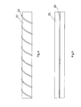
- FIG 5 shows a gas line 20 with a fire monitoring device 26 according to one of the embodiments shown in Figs. 1-4 has been described.
- the fire monitoring device 26 is not on the gas line 20 here arranged, but integrated into this.
Landscapes
- Business, Economics & Management (AREA)
- Emergency Management (AREA)
- Physics & Mathematics (AREA)
- General Physics & Mathematics (AREA)
- Fire-Detection Mechanisms (AREA)
Abstract
Description
- Fig. 1
- eine Vorderansicht einer Brandüberwachungsvorrichtung gemäß einer ersten Ausführungsform der Erfindung,
- Fig. 2
- eine Vorderansicht einer Brandüberwachungsvorrichtung gemäß einer zweiten Ausführungsform der Erfindung,
- Fig. 3
- eine Vorderansicht einer Gasleitung mit einer Brandüberwachungsvorrichtung gemäß einer dritten Ausführungsform der Erfindung,
- Fig. 4
- eine Vorderansicht einer Gasleitung mit einer Brandüberwachungsvorrichtung gemäß einer vierten Ausführungsform der Erfindung, und
- Fig. 5
- eine Vorderansicht einer Gasleitung mit einer Brandüberwachungsvorrichtung gemäß einer der Ausführungsformen, die in den Fign. 1 - 4 dargestellt ist.
Claims (19)
- Rohr (20) mit einer Brandüberwachungsvorrichtung, miteiner kontinuierlichen Detektoranordnung, die sich im wesentlichen in Längsrichtung des Rohres (20) erstreckt,wobei die Detektoranordnung eine Mehrzahl von metallischen Leitern (10,12;14,16) aufweist,wobei wenigstens einer der metallischen Leiter eine Isolierschicht aufweist, die unter Einfluss der bei einem Brand entstehenden Wärme schmilzt undwobei die Berührung der Leiter bei geschmolzener Isolierschicht zur Erzeugung eines einen Brand anzeigenden Signals ausnutzbar ist.
- Rohr (20) mit einer Brandüberwachungsvorrichtung nach Anspruch 1, dadurch gekennzeichnet, dass die Isolierschicht einen Schmelzpunkt aufweist, der im Bereich von 100°C liegt.
- Rohr (20) mit einer Brandüberwachungsvorrichtung nach einem der vorhergehenden Ansprüche, dadurch gekennzeichnet, dass die Isolierschicht ein Kunststoffmaterial aufweist.
- Rohr (20) mit einer Brandüberwachungsvorrichtung nach einem der vorhergehenden Ansprüche, dadurch gekennzeichnet, dass die Isolierschicht einen Lack aufweist.
- Rohr (20) mit einer Brandüberwachungsvorrichtung nach einem der vorhergehenden Ansprüche, dadurch gekennzeichnet, dass die metallischen Leiter (10,12;14,16) derart verdrillt sind, dass sie miteinander mechanisch verspannt sind.
- Rohr (20) mit einer Brandüberwachungsvorrichtung nach Anspruch 5, dadurch gekennzeichnet, dass die metallischen Leiter (10,12;14,16) auf Grund der jeweils verwendeten Materialien eine unterschiedliche mechanische Festigkeit aufweisen.
- Rohr (20) mit einer Brandüberwachungsvorrichtung nach einem der vorhergehenden Ansprüche, dadurch gekennzeichnet, dass zusammen mit den metallischen Leitern (14,16) ein weiterer stromdurchflossener Leiter (18) mit einer Isolierschicht mit hohem Schmelzpunkt angeordnet ist, wobei bei Durchtrennung des stromdurchflossenen Leiters (18) eine Fehlermeldung in Form eines Signals ausgegeben wird.
- Rohr (20) mit einer Brandüberwachungsvorrichtung nach Anspruch 7, dadurch gekennzeichnet, dass der stromdurchflossene Leiter (18) Kupfer umfasst.
- Rohr (20) mit einer Brandüberwachungsvorrichtung nach Anspruch 7 oder 8, dadurch gekennzeichnet, dass die Isolierschicht des stromdurchflossenen Leiters (18) einen Lack aufweist.
- Rohr (20) mit einer Brandüberwachungsvorrichtung, miteiner kontinuierlichen Detektoranordnung, die sich im wesentlichen in Längsrichtung des Rohres (20) erstreckt,wobei die Detektoranordnung wenigstens einen metallischen Leiter (22) aufweist,wobei der metallische Leiter (22) einen elektrischen Widerstand aufweist, der sich bei Einwirkung von Wärme ändert undwobei die Änderung des elektrischen Widerstandes zur Erzeugung eines einen Brand anzeigenden Signals anwendbar ist.
- Rohr (20) mit einer Brandüberwachungsvorrichtung nach Anspruch 10, dadurch gekennzeichnet, dass der Widerstand mit zunehmender Temperatur deutlich zunimmt.
- Rohr (20) mit einer Brandüberwachungsvorrichtung nach Anspruch 10, dadurch gekennzeichnet, dass der Widerstand mit zunehmender Temperatur deutlich abnimmt.
- Rohr (20) mit einer Brandüberwachungsvorrichtung, miteiner kontinuierlichen Detektoranordnung, die sich im wesentlichen in Längsrichtung des Rohres (20) erstreckt,wobei die Detektoranordnung wenigstens einen metallischen Leiter (24) aufweist,wobei durch den metallischen Leiter (24) kontinuierlich ein Strom fließt,wobei der metallische Leiter (24) ein Material aufweist, das unter Einfluss der durch einen Brand erzeugten Wärme schmilzt, wodurch der Leiter (24) durchtrennt wird, undwobei die Durchtrennung des Leiters (24) zur Erzeugung eines einen Brand anzeigenden Signals anwendbar ist.
- Rohr (20) mit einer Brandüberwachungsvorrichtung nach Anspruch 13, dadurch gekennzeichnet, dass der metallische Leiter (24) Weichlot umfasst.
- Rohr (20) mit einer Brandüberwachungsvorrichtung nach einem der vorhergehenden Ansprüche, dadurch gekennzeichnet, dass der bzw. die metallischen Leiter (10,12;14,16,18;22;24) an dem Rohr (20) befestigt sind.
- Rohr (20) mit einer Brandüberwachungsvorrichtung nach einem der vorhergehenden Ansprüche, dadurch gekennzeichnet, dass der bzw. die metallischen Leiter (10,12;14,16,18;22;24;26) in das Rohr (20) integriert sind.
- Rohr (20) mit einer Brandüberwachungsvorrichtung nach einem der vorhergehenden Ansprüche, dadurch gekennzeichnet, dass der bzw. die metallischen Leiter (10,12;14,16,18;22;24;26) schraubenlinienförmig an dem Durchmesser des Rohres (20) angeordnet sind.
- Rohr (20) mit einer Brandüberwachungsvorrichtung nach einem der vorhergehenden Ansprüche, dadurch gekennzeichnet, dass das Rohr (20) ein Kunststoffmaterial, ein metallisches Material oder ein Kunststoff/Metall-Verbundmaterlal aufweist.
- Rohr (20) mit einer Brandüberwachungsvorrichtung nach einem der vorhergehenden Ansprüche, dadurch gekennzeichnet, dass das Rohr (20) eine Gasleitung ist.
Applications Claiming Priority (2)
| Application Number | Priority Date | Filing Date | Title |
|---|---|---|---|
| DE10033634 | 2000-07-11 | ||
| DE10033634 | 2000-07-11 |
Publications (2)
| Publication Number | Publication Date |
|---|---|
| EP1172779A2 true EP1172779A2 (de) | 2002-01-16 |
| EP1172779A3 EP1172779A3 (de) | 2003-02-12 |
Family
ID=7648528
Family Applications (1)
| Application Number | Title | Priority Date | Filing Date |
|---|---|---|---|
| EP01116914A Withdrawn EP1172779A3 (de) | 2000-07-11 | 2001-07-11 | Rohr mit integrierter Brandüberwachungsvorrichtung |
Country Status (1)
| Country | Link |
|---|---|
| EP (1) | EP1172779A3 (de) |
Cited By (3)
| Publication number | Priority date | Publication date | Assignee | Title |
|---|---|---|---|---|
| US11047761B1 (en) | 2018-02-08 | 2021-06-29 | Moen Incorporated | Integrated leak detection |
| DE102020132340A1 (de) | 2020-12-04 | 2022-06-09 | Intilion Gmbh | Energiespeichervorrichtung, Überwachungseinheit für eine Energiespeichervorrichtung und Verfahren zur Herstellung einer Energiespeichervorrichtung |
| US11519814B2 (en) | 2019-02-15 | 2022-12-06 | Fb Global Plumbing Group Llc | Fluid usage monitoring and control system |
Citations (9)
| Publication number | Priority date | Publication date | Assignee | Title |
|---|---|---|---|---|
| US5183079A (en) | 1989-07-05 | 1993-02-02 | Hutchinson S.A. | Heat and fire resistant protective covering for hoses, cables and the like |
| US5329972A (en) | 1987-03-13 | 1994-07-19 | Shell Internationale Research Maatschappij B.V. | Fire resistant plastic structure |
| DE4316584C1 (de) | 1993-05-18 | 1994-09-08 | Knebel Heinz Hermann | Armatur zum Absperren von mit Hausanschlüssen verbundenen und mit Gasen beaufschlagten Versorgungsleitungen sowie Einrichtung zum Steuern der Armatur |
| WO1994025791A1 (en) | 1993-05-03 | 1994-11-10 | Ameron | Fire-resistant structural member and method of production |
| DE4326072A1 (de) | 1993-08-04 | 1995-02-09 | Ruhrgas Ag | Vorrichtung zum automatischen Schließen einer Absperrarmatur |
| DE29611260U1 (de) | 1996-06-30 | 1996-09-26 | Denk, Oliver, Dipl.-Ing., 44309 Dortmund | Vorrichtung zum Absperren von Fluiden und gasförmigen Stoffen |
| US5562957A (en) | 1992-11-05 | 1996-10-08 | Trelleborg Viking As | Multilayer fire protective coating |
| DE19600369A1 (de) | 1995-07-12 | 1997-01-16 | Gert Bartholomaeus | Brandschutzeinrichtung zur Abschottung einer Rohrleitung |
| DE19532289C1 (de) | 1995-09-01 | 1997-02-06 | Schlumberger Rombach Gmbh | Gasgerät |
Family Cites Families (4)
| Publication number | Priority date | Publication date | Assignee | Title |
|---|---|---|---|---|
| GB653864A (en) * | 1948-07-06 | 1951-05-30 | Ralph Poole | Improvements in or relating to fire detecting devices and apparatus embodying such devices |
| US4157526A (en) * | 1977-02-22 | 1979-06-05 | Davies John S | Multi-stage heat sensing cable and emergency communication system |
| DE3904949A1 (de) * | 1989-02-18 | 1990-08-23 | Christian Dr Thoma | Alarmeinrichtung |
| JPH0896630A (ja) * | 1994-09-26 | 1996-04-12 | Furukawa Electric Co Ltd:The | 火災検知線 |
-
2001
- 2001-07-11 EP EP01116914A patent/EP1172779A3/de not_active Withdrawn
Patent Citations (9)
| Publication number | Priority date | Publication date | Assignee | Title |
|---|---|---|---|---|
| US5329972A (en) | 1987-03-13 | 1994-07-19 | Shell Internationale Research Maatschappij B.V. | Fire resistant plastic structure |
| US5183079A (en) | 1989-07-05 | 1993-02-02 | Hutchinson S.A. | Heat and fire resistant protective covering for hoses, cables and the like |
| US5562957A (en) | 1992-11-05 | 1996-10-08 | Trelleborg Viking As | Multilayer fire protective coating |
| WO1994025791A1 (en) | 1993-05-03 | 1994-11-10 | Ameron | Fire-resistant structural member and method of production |
| DE4316584C1 (de) | 1993-05-18 | 1994-09-08 | Knebel Heinz Hermann | Armatur zum Absperren von mit Hausanschlüssen verbundenen und mit Gasen beaufschlagten Versorgungsleitungen sowie Einrichtung zum Steuern der Armatur |
| DE4326072A1 (de) | 1993-08-04 | 1995-02-09 | Ruhrgas Ag | Vorrichtung zum automatischen Schließen einer Absperrarmatur |
| DE19600369A1 (de) | 1995-07-12 | 1997-01-16 | Gert Bartholomaeus | Brandschutzeinrichtung zur Abschottung einer Rohrleitung |
| DE19532289C1 (de) | 1995-09-01 | 1997-02-06 | Schlumberger Rombach Gmbh | Gasgerät |
| DE29611260U1 (de) | 1996-06-30 | 1996-09-26 | Denk, Oliver, Dipl.-Ing., 44309 Dortmund | Vorrichtung zum Absperren von Fluiden und gasförmigen Stoffen |
Cited By (3)
| Publication number | Priority date | Publication date | Assignee | Title |
|---|---|---|---|---|
| US11047761B1 (en) | 2018-02-08 | 2021-06-29 | Moen Incorporated | Integrated leak detection |
| US11519814B2 (en) | 2019-02-15 | 2022-12-06 | Fb Global Plumbing Group Llc | Fluid usage monitoring and control system |
| DE102020132340A1 (de) | 2020-12-04 | 2022-06-09 | Intilion Gmbh | Energiespeichervorrichtung, Überwachungseinheit für eine Energiespeichervorrichtung und Verfahren zur Herstellung einer Energiespeichervorrichtung |
Also Published As
| Publication number | Publication date |
|---|---|
| EP1172779A3 (de) | 2003-02-12 |
Similar Documents
| Publication | Publication Date | Title |
|---|---|---|
| DE69019114T2 (de) | Verfahren und Verbindungsteil mit einem elektrischen Widerstand zum Verschweissen von Elementen aus thermoplastischem Material. | |
| DE102015215384A1 (de) | Elektrische Durchführung und ihre Verwendung | |
| DE102013202614A1 (de) | Störfallresistente Durchführung | |
| EP3640605A1 (de) | Füllstandsüberwachungssystem und durchflussmessgerät | |
| DE202017105705U1 (de) | Sprinklerkopf | |
| EP3349866B1 (de) | Rohrheizung | |
| DE10056778A1 (de) | Brandschutzanlage mit Glasfasssensoren | |
| EP0018536A1 (de) | Rissanzeigeeinrichtung zur Überwachung der Isolierung von Flüssiggastanks | |
| EP3669951A1 (de) | Elektrisch auslösbareres schmelzlotöffnungselement eines löschfluidleitenden elementes | |
| EP1369636B1 (de) | Elektroschweissmuffe | |
| EP4240496A1 (de) | Überwachungs- und löschvorrichtung | |
| DE19547031A1 (de) | Langgestreckte rohrförmige Hülle | |
| DE60120190T2 (de) | Verfahren und vorrichtung zur vorwärmung von kabelleiterelementen mit extrudierter isolierung ,besonders leiter mit metallbandverstärkung | |
| AT404980B (de) | Absperrvorrichtung für eine gasversorgungsleitung | |
| DE3414603C2 (de) | ||
| DE10029244A1 (de) | Elektrische Heizvorrichtung | |
| DE102011089942A1 (de) | Aufnahmevorrichtung für einen Messeinsatz | |
| DE102008002871B4 (de) | Messanordnung | |
| CH213362A (de) | Vorrichtung an Flugzeugen zum Anzeigen der Vereisungsgefahr. | |
| CH652520A5 (en) | Fire alarm system, in particular for a road tunnel | |
| DE102004014831B4 (de) | Berstschlauch für Feuerlöschsysteme | |
| DE60038301T2 (de) | Isolierte tracer-leitung in einem rohr mit geregelter leitfähigkeit und verfahren zur herstellung dieser tracer-leitung | |
| DE19544159C1 (de) | Gefäßmantelsicherung | |
| DE102011105162A1 (de) | Düse | |
| DE1807641C (de) | Fühler für die Wärmemeldung |
Legal Events
| Date | Code | Title | Description |
|---|---|---|---|
| PUAI | Public reference made under article 153(3) epc to a published international application that has entered the european phase |
Free format text: ORIGINAL CODE: 0009012 |
|
| AK | Designated contracting states |
Kind code of ref document: A2 Designated state(s): AT BE CH CY DE DK ES FI FR GB GR IE IT LI LU MC NL PT SE TR |
|
| AX | Request for extension of the european patent |
Free format text: AL;LT;LV;MK;RO;SI |
|
| PUAL | Search report despatched |
Free format text: ORIGINAL CODE: 0009013 |
|
| AK | Designated contracting states |
Designated state(s): AT BE CH CY DE DK ES FI FR GB GR IE IT LI LU MC NL PT SE TR |
|
| AX | Request for extension of the european patent |
Extension state: AL LT LV MK RO SI |
|
| RIC1 | Information provided on ipc code assigned before grant |
Ipc: 7G 08B 17/06 B Ipc: 7G 08B 17/02 A |
|
| 17P | Request for examination filed |
Effective date: 20030806 |
|
| AKX | Designation fees paid |
Designated state(s): AT BE CH CY DE DK ES FI FR GB GR IE IT LI LU MC NL PT SE TR |
|
| 17Q | First examination report despatched |
Effective date: 20031205 |
|
| STAA | Information on the status of an ep patent application or granted ep patent |
Free format text: STATUS: THE APPLICATION IS DEEMED TO BE WITHDRAWN |
|
| 18D | Application deemed to be withdrawn |
Effective date: 20040616 |