EP1171240B1 - Pipettenspitze, pipettiervorrichtung und kombination aus pipettenspitze und pipettiervorrichtung - Google Patents
Pipettenspitze, pipettiervorrichtung und kombination aus pipettenspitze und pipettiervorrichtung Download PDFInfo
- Publication number
- EP1171240B1 EP1171240B1 EP00926950A EP00926950A EP1171240B1 EP 1171240 B1 EP1171240 B1 EP 1171240B1 EP 00926950 A EP00926950 A EP 00926950A EP 00926950 A EP00926950 A EP 00926950A EP 1171240 B1 EP1171240 B1 EP 1171240B1
- Authority
- EP
- European Patent Office
- Prior art keywords
- pipette tip
- pipette
- coupling
- axial
- unit according
- Prior art date
- Legal status (The legal status is an assumption and is not a legal conclusion. Google has not performed a legal analysis and makes no representation as to the accuracy of the status listed.)
- Expired - Lifetime
Links
- 230000008878 coupling Effects 0.000 claims abstract description 88
- 238000010168 coupling process Methods 0.000 claims abstract description 88
- 238000005859 coupling reaction Methods 0.000 claims abstract description 88
- 238000007789 sealing Methods 0.000 claims description 27
- 230000006835 compression Effects 0.000 claims description 4
- 238000007906 compression Methods 0.000 claims description 4
- 239000004020 conductor Substances 0.000 claims description 3
- 238000013459 approach Methods 0.000 description 18
- 230000002093 peripheral effect Effects 0.000 description 10
- 239000007788 liquid Substances 0.000 description 7
- 230000000295 complement effect Effects 0.000 description 6
- 239000000463 material Substances 0.000 description 6
- 239000000243 solution Substances 0.000 description 5
- 230000007704 transition Effects 0.000 description 4
- 239000012530 fluid Substances 0.000 description 3
- 230000003993 interaction Effects 0.000 description 3
- 239000004033 plastic Substances 0.000 description 3
- 238000007654 immersion Methods 0.000 description 2
- 238000012546 transfer Methods 0.000 description 2
- 208000034656 Contusions Diseases 0.000 description 1
- 230000008901 benefit Effects 0.000 description 1
- 208000034526 bruise Diseases 0.000 description 1
- 238000005253 cladding Methods 0.000 description 1
- 238000013461 design Methods 0.000 description 1
- 238000001746 injection moulding Methods 0.000 description 1
- 238000003780 insertion Methods 0.000 description 1
- 230000037431 insertion Effects 0.000 description 1
- 238000009434 installation Methods 0.000 description 1
- 239000011159 matrix material Substances 0.000 description 1
- 238000005259 measurement Methods 0.000 description 1
- 229910052751 metal Inorganic materials 0.000 description 1
- 239000002184 metal Substances 0.000 description 1
- 150000002739 metals Chemical class 0.000 description 1
- 239000002245 particle Substances 0.000 description 1
- 230000036316 preload Effects 0.000 description 1
- 230000009467 reduction Effects 0.000 description 1
Images




Classifications
-
- B—PERFORMING OPERATIONS; TRANSPORTING
- B01—PHYSICAL OR CHEMICAL PROCESSES OR APPARATUS IN GENERAL
- B01L—CHEMICAL OR PHYSICAL LABORATORY APPARATUS FOR GENERAL USE
- B01L3/00—Containers or dishes for laboratory use, e.g. laboratory glassware; Droppers
- B01L3/02—Burettes; Pipettes
- B01L3/0275—Interchangeable or disposable dispensing tips
- B01L3/0279—Interchangeable or disposable dispensing tips co-operating with positive ejection means
Definitions
- the invention is concerned with the attachment of a pipette tip to a Pipetting.
- Pipetting devices are used, for example, in the field of molecular biology or medical analysis for fluid transfer. Special pipette tips are often used, which on the Pipetting device can be attached and intended for single use are. Such disposable tips are also known as "tip" known.
- the pipetting device can be a manual one Actuate pipetting device that only a single pipetting unit having.
- pipetting machines or So-called pipetting robots are used, which are a variety of in a row or have pipetting units arranged in a matrix. With such Automatic pipetting machines can simultaneously use a variety of tubes Samples are sucked in and released again at another point.
- a pipetting unit described in EP 0 760 255 A1 has one adjustable pretensioning element in the form of an inflatable rubber sleeve, whose edge facing the pipette tip on a radial Axial stop surface of the pipette tip is in contact. Because the edge of the Rubber sleeve is more or less elastic, but can not be spoken of a precisely maintained coupling position in the event of an attack become. If the pipette tip does not touch the Edge of the rubber sleeve is pushed on, but its Stop surface a more or less large clear distance to Has rubber collar, this distance remains when inflating the Rubber sleeve more or less obtained what the positioning accuracy drastically frittered away.
- a defined position of the pipette tip is relative to the coupling attachment however, particularly in the case of automatic pipetting machines which have a large number of pipetting units have essential.
- Different Positioning of the pipette tips in pipetting machines with several For example, ten or even several hundred pipetting units can be used of liquid aspiration cause some pipette tips properly in the vessels or recesses assigned to them immerse a microtiter plate while other pipette tips are over the Liquid levels remain in the vessels or depressions.
- individual pipette tips at the bottom of the vessels or Initiate depressions and thereby at least their mouth opening is partially blocked. The consequence can be insufficient dosing accuracy in both fluid intake and fluid delivery his.
- the object of the invention is therefore to show a way, in particular in automatic pipetting devices with a variety of Pipetting units improve the dosing accuracy during liquid transfer can be.
- the present invention provides a solution to the stated problem a pipetting unit according to claim 1.
- the pipette tip for attachment to a pipetting device
- the pipette tip has a jacket and one enclosed by the jacket Through opening, the through opening along a longitudinal axis between one to be pipetted for immersion Medium determined end of the pipette tip and one in Axial direction opposite to the tip of the pipette extends and wherein the pipette tip near the plug end Coupling area for coupling with a coupling attachment of the pipetting device having.
- the jacket in the coupling area Axial positioning means which cooperates with complementary counter-axial positioning means of the coupling approach are determined and together with the counter-axial positioning means an axial coupling position of the pipette tip on the pipetting device define.
- the axial positioning means make it possible for everyone Always attach the pipette tip to the pipetting device predetermined defined axial position of the pipette tip relative to the Obtain pipetting device. This enables a positionally accurate and Equipped in the same position for all pipetting units of an automatic pipetting machine with pipette tips.
- the tip of the pipette is on with its push-on end the coupling attachment can be plugged on, which is why the axial positioning means expediently at least in part on the inner circumference of the jacket in axial distance from the push-on end of the pipette tip will be.
- the inner circumference of the jacket can be at least in the coupling area an envelope formed essentially by cylindrical sections have.
- the axial positioning means can have at least one on the jacket arranged axial stop, which cooperate with a complementary counterstop of the coupling approach is determined.
- the Axial stop in engagement with the counter stop of the coupling attachment, which results in a defined axial position of the pipette tip.
- the coupling attachment also carries an elastically deformable O-ring that due to axial crushing and the resulting radial expansion in has come into frictional engagement with a sealing surface of the pipette tip a particularly simple, yet highly accurate attachment option for given the pipette tip on the pipetting device.
- the axial stop can be easily manufactured from an axial Step heel of the inner circumference of the jacket be formed, which one Sliding closer first cylindrical inner circumferential section larger diameter with one further away from the push-on end second cylindrical inner circumferential section of smaller diameter combines.
- the following dimensions are recommended:
- the by the Graduated step caused diameter reduction from the first to the second inner circumferential section can be between 0.8 and 1.2 mm, preferably between 0.9 and 1.1 mm, most preferably about 1.0 mm be.
- the diameter of the first inner circumferential section can between 6.5 and 7.1 mm, preferably between 6.7 and 6.9 mm, most preferably about 6.8 mm.
- the diameter of the As far as the second inner circumferential section is concerned this can be between 5.5 and 6.1 mm, preferably between 5.7 and 5.9 mm, most preferably about 5.8 mm. It is recommended to use a standard coupling interface between the pipette tip and the pipetting device to define, so that pipette tips with different recording volumes for liquids to be pipetted, but with standardized coupling areas, can be combined with one and the same pipetting device.
- the sealing element of an O-ring are formed and according to US-A-5,063,790 by a Squeeze device of the pipetting device to be axially compressible. It can then be provided that the attack surface designed and attached to the jacket is localized in the coupling position of the pipette tip the sealing element in an axially uncompressed state in essentially except for pre-tensioning engagement with the surface of the attack stands and in the course of an axial compression in prestressing force generators Engages with the attack surface.
- the attack surface can be, for example, in the inner circumference of the jacket incorporated circumferential groove into which the sealing element of the Coupling approach can "snap".
- the circumferential groove can be curved in a circular arc be, their radius of curvature between 0.3 and 0.9 mm, preferably between 0.4 and 0.8 mm, most preferably between 0.5 and 0.7 mm can be.
- the contact surface is preferably axially between the Axial stop and the second end of the pipette tip arranged.
- a pipetting device with at least one pipetting unit which has a pipetting channel running along a channel axis and a coupling approach for coupling a pipette tip in particular of the type described above, has the Coupling approach for interaction with axial positioning means of Pipette tip certain complementary counter-axial positioning means which, together with the axial positioning means, has an axial Define the coupling position of the pipette tip on the pipetting unit.
- the coupling attachment can be plugged into the Pipette tip can be inserted, it then being expedient recommends that the counter-axial positioning means be at least partially on the Outer periphery of the coupling approach at an axial distance from the push-on end to arrange.
- the inner circumference of the pipette tip can be the outer circumference of the Coupling approach at least in the in the coupling position in the Pipette tip protruding area of the coupling attachment in essentially have envelopes formed by cylindrical sections.
- the counter-axial positioning means can be at least one for Determine interaction with an axial stop of the pipette tip complement complementary counterstop on the coupling approach.
- This Counterstop can be from a step heel on the outer circumference of the Coupling approach be formed.
- the coupling attachment can be a seal between the pipette tip and the coupling element serving sealing element, in particular an O-ring, wear from elastically deformable material, the pipetting unit Assigned squeezing device for axially compressing the sealing element can be.
- the sealing element can not only perform a sealing function, but also take on a pretension function if the Pipette tip an appropriately designed and localized target for the sealing element, which has a radial surface component and loaded with an axial force component from the sealing element can be.
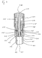
- FIG. 1 You can also see one there as a tip designated pipette tip 1 with a rotationally symmetrical about a longitudinal axis 3 Jacket 5, the one axially passing through the pipette tip 1 Encloses through opening 7.
- the pipette tip 1 has a coupling area 11, that for coupling to a pipetting device not shown in FIG. 1 serves.
- the pipette tip has the plug-on end 9 opposite 1 has a mouth end 13 which is to be pipetted for immersion in Medium is determined.
- the jacket 5 of the pipette tip 1 has an outer circumference 15 and one Inner circumference 17.
- the inner circumference 17 has in the coupling region 11 a cylindrical inner peripheral portion 19 which is substantially from the push-on end 9 extends to an annular step heel 21, to the another cylindrical inner circumferential section 23 connects.
- the Step heel 21 forms an axially directed stop surface.
- In the area of Inner peripheral portion 19 is an annular groove extending in the circumferential direction 25 incorporated into the jacket 5.
- This axially between the push-on end 9 and the step groove 21 arranged annular groove 25 has in the sectional view 1 is a groove contour that follows an arc.
- the jacket 5 has a first conical wall section 27 and a second conical wall section 29, whose taper is weaker than that of the wall section 27.
- the area of the wall sections 27 and 29 is the jacket 5 with a smaller one Wall thickness than in the coupling area 11.
- the bigger wall thickness in the coupling area 11 increases the stability and rigidity of the Pipette tip 1. This allows a safe and leak-free coupling of the Pipette tip 1 to a pipetting device.
- Inner diameter of the jacket 5 in the area of the inner peripheral portion 19 are approximately 6.8 mm and in the area of the inner circumferential section 23 about 5.8 mm.
- the step heel 21 can be at an axial distance be arranged from the front end 9 of about 5 mm.
- the radius of curvature the circular contour of the annular groove 25 can be approximately 0.6 mm.
- the maximum radial depth of the annular groove 25 can be approximately 0.2 mm.
- the axial distance between the step 21 and the axial center of the annular groove 25, that is, its lowest point, can be approximately 2.1 mm.
- a section of a pipetting unit can be seen in the upper part of FIG. 2 201, which is part of a manually or automatically operated pipetting device is and has a coupling approach 203, which for coupling with the Pipette tip 101 is determined.
- the mentioned pipetting device can train a variety of such pipetting units when trained as a pipetting robot 201 wear, for example up to a few hundred.
- the pipetting unit 201 has a pipetting tube 205, which has a pipetting channel 207 contains, which runs along a channel axis 209 and in the coupling state the pipette tip 101 on the pipetting unit 201 from the Through opening 107 of the pipette tip 101 is continued.
- the Coupling attachment 203 comprises one fixed to the lower end of the pipetting tube 205 attached to this, for example pressed or screwed Coupling sleeve 211.
- An O-ring 213 made of elastically deformable and if desired, electrically conductive material is on the pipetting tube 205 pushed on and lies on the pipette tip 101 axially facing away Front side of the coupling sleeve 211.
- a ferrule 215 is on the Pipette tube 205 pushed on. This ferrule 215 is axially relative to the pipetting tube 205 slidably and serves for the axial crushing of the O-sealing rings 213.
- the crimp sleeve 215 is by means of not shown Actuating means can be actuated. These actuators can be manual or allow automatic actuation of the ferrule 215.
- the crimp sleeve 215 can be actuated hydraulically. It is also conceivable to use a screw drive for adjusting the crimp sleeve Provide 215, which can be operated by hand, but also can be actuated by means of an electric motor.
- step heels 121, 219 By working together of these two step heels 121, 219 is in the final assembly state the axial position of the pipette tip 101 relative to the pipetting unit 201 exactly defined.
- Fig. 3 shows the state when the pipette tip 101 is attached and the O-ring 213 is still not crimped. It can be seen that the axial Distance of the step shoulder 219 of the coupling sleeve 211 from the axial End face of the coupling sleeve 211, on which the O-ring 213 rests, such is dimensioned that in the plug-on position shown in Fig. 3, the 0-seal 213 is axially offset somewhat from the annular groove 125. More accurate said is the axial center of the annular groove 125 with respect to the axial Center of the uncompressed O-ring 213 slightly towards the pipette tip 101 offset.
- FIGS. 4 and 4a show the state in which the pinch of the O-ring 213 is completed and the final assembly position of the pipette tip 101 on the Pipetting unit 201 is manufactured, and of which Fig. 4a one shows enlarged section in the area of the O-ring 213.
- the ferrule 215 is on a leading tip 225 at its end facing the O-ring 213 which, when the ferrule 215 approaches the o-ring 213 penetrates between this and the pipetting tube 205, so that the O-ring 213 is not only compressed axially, but by the tip 225 is also pressed radially somewhat towards the annular groove 125.
- the O-ring 213 is enlarged as a result of being crushed of its outside diameter. Its radially pushed out parts can be in escape the space saved by the annular groove 125, which is shown in Fig. 4a is indicated by dashed lines.
- the parts of the O-rings 213 try to relax in the ring groove 125 and expand, where they come to rest on the bottom of the annular groove 125 and push against it.
- the axial offset of the Ring groove 125 opposite the O-ring 123 causes the O-ring 213 primarily against the axially upper region of FIG. 4a Bottom of the ring groove 125 presses.
- the bottom of the Ring groove 125 an engagement surface 127 for the O-ring 213.
- This Attack surface 127 has a radial component due to its curvature, so that when the O-ring 213 against the attack surface 127 presses a force on the pipette tip 101 with an axial Component is exercised.
- the crimp sleeve 215 is removed from it in Fig. 4 pinched position axially raised, whereby the O-ring 213 relaxed again and withdrawn from the ring groove 125.
- the 4 to the step heels 121, 219
- the pre-tensioning force is released. It finally turns out again the state shown in FIG. 3.
- the O-ring is expediently 213 not completely out of contact in this state according to FIG. 3 with the inner circumference 117 of the pipette tip 101, but in such Engagement with the inner circumference 117 of the pipette tip 101 that the Pipette tip 101 does not fall off the pipetting unit 201 on its own.
- the O-ring can, for example, in this situation 213 at the transition edge designated by 129 between the Annular groove 125 and the cylindrical inner peripheral portion 119 of the Trigger pipette tip 101.
- this transition edge 129 moves past the O-ring 213 be what only under a simultaneous slight radial compression of the O-ring 213 is possible.
- This radial compression of the O-ring 213, however, increases friction, which in itself Demand for a smooth wiping of the pipette tip 101 from would run counter to the pipetting unit 201.
- the cylindrical inner peripheral portion located above the annular groove 125 119 of the pipette tip 101 is preferably staggered, as is the case with this can be seen in particular in FIG. 4a.
- the ejector 217 is provided to be accomplished manually. This can be operated in a variety of ways. For example hydraulic or electromotive actuation of the ejector 217 conceivable. Alternatively, a not shown on the ejector 217 Attack biasing spring, which when placing the pipette tip 101 on the Pipetting unit 201 is clamped when the pipette tip 101 with its End 109 of the ejector tube forming the ejector 217 upwards suppressed. If the pinch of the O-ring 213 is then removed, this ejector spring can relax again.
- the Ejector pretensioning spring will be dimensioned so that it in the tensioned state on the ejector tube 217 not the force axial holding force of the O-ring 213 exceeds. At the same time it will be like this be measured in such a way that the force exerted on the Pipette tip 101 is applied, sufficient to the edge 129 on the O-ring 213 moving past.
- Fig. 5 shows the release state in which the ejector 217 is down is moved and the pipette tip 101 completely on the O-sealing ring 213 has passed.
- Suction means can, for example, axially in the pipetting tube 205 comprise movably arranged pistons which are operated by means of electrical hydraulic or pneumatic actuating means is axially adjustable.
- the pipette tip 101 is preferably made of a plastic material manufactured, for example by injection molding.
- This plastic material can be electrically conductive to conduct conductivity measurements in a manner known per se to be able to perform on the liquid to be pipetted.
- the coupling sleeve 211 and the pipetting tube can 205 consist of conductive materials.
- Plastic materials for the coupling sleeve 211 and the pipetting tube 205 are not excluded.
- the capacity of as a disposable item trained pipette tip 101 can for example between 0.1 and 1300 ⁇ l.
Landscapes
- Health & Medical Sciences (AREA)
- Clinical Laboratory Science (AREA)
- Chemical & Material Sciences (AREA)
- Chemical Kinetics & Catalysis (AREA)
- Automatic Analysis And Handling Materials Therefor (AREA)
- Devices For Use In Laboratory Experiments (AREA)
Description
- Fig. 1
- im Schnitt ein Ausführungsbeispiel einer erfindungsgemäßen Pipettenspitze und
- Fig. 2-5
- Situationen beim Ankoppeln einer Pipettenspitze an eine Pipettiervorrichtung und beim Abwerfen der Pipettenspitze.
Claims (13)
- Pipettiereinheit (201) mit Pipettenspitze für eine Pipettiervorrichtung, wobei die Pipittiereinheit (201) einen Koppelansatz (203) aufweist, auf welchen die Pipettierspitze in einer Aufsteckrichtung zur Ankopplung aufsteckbar ist, wobei der Koppelansatz (203) ein verstellbares Vorspannorgan (213) aufweist, welches über eine im Koppelansatz vorgesehene Betätigungseinrichtung (215) in einen Vorspannzustand und einen Freigabezustand verstellbar ist,
dadurch gekennzeichnet, daß die Pipettenspitze (101) einen Axialanschlag (121) aufweist, der in einer axialen Ankopplungsstellung der Pipettenspitze (101) mit einem Gegenanschlag (219) des Koppelansatzes (203) zusammenwirkt, daß das Vorspannorgan (213) in seinem Vorspannzustand an einer Angriffsfläche (127) der aufgesteckten Pipettierspitze (101) mit von der Aufsteckrichtung abgewandter, radial nach innen verlaufender Flächenkomponente der Pipettenspitze (101) derart angreift, daß es an der Angriffsfläche abdichtend anliegt und die Pipettenspitze (101) in die axiale Ankoppelstellung vorspannt und daß das Vorspannorgan (213) in seinem Freigabezustand die Angriffsfläche (127) der Pipettenspitze (101) im wesentlichen freigibt. - Pipettiereinheit (201) nach Anspruch 1, dadurch gekennzeichnet, daß die Angriffsfläche (127) von einer Ringnut (125) gebildet ist.
- Pipettiereinheit nach Anspruch 1 oder 2, dadurch gekennzeichnet, daß der Axialanschlag (121) mindestens zum Teil an einem Innenumfang (117) eines Mantels (105) der Pipettierspitze in axialem Abstand vom Aufsteckende (109) der Pipettenspitze (101) angeordnet sind.
- Pipettiereinheit nach Anspruch 3, dadurch gekennzeichnet, daß der Mantelinnenumfang (117) zumindest in dem Koppelbereich (111) eine im wesentlichen von zylindrischen Abschnitten (119, 123) gebildete Einhüllende besitzt.
- Pipettiereinheit nach einem der vorhergehenden Ansprüche, dadurch gekennzeichnet, daß der Axialanschlag (121) von einem Stufenabsatz des Mantelinnenumfangs (117) gebildet ist, welcher einen dem Aufsteckende (109) näheren ersten zylindrischen Mantelinnenumfangsabschnitt (119) größeren Durchmessers mit einem dem Aufstekende (109) ferneren zweiten zylindrischen Mantelinnenumfangsabschnitt (123) kleineren Durchmessers verbindet.
- Pipettiereinheit nach Anspruch 5, dadurch gekennzeichnet, daß die durch den Stufenabsatz (121) bewirkte Durchmesserverkleinerung vom ersten (119) zum zweiten (123) Mantelinnenumfangsabschnitt zwischen 0,8 und 1,2 mm beträgt.
- Pipettiereinheit nach Anspruch 5 oder 6, dadurch gekennzeichnet, daß der Durchmesser des ersten Mantelinnenumfangsabschnitts (119) zwischen 6,5 und 7,1 mm beträgt.
- Pipettiereinheit nach einem der Ansprüche 5 bis 7, dadurch gekennzeichnet, daß der Durchmesser des zweiten Mantelinnenumfangsabschnitts (123) zwischen 5,5 und 6,1 mm beträgt.
- Pipettiereinheit nach einem der vorhergehenden Ansprüche, dadurch gekennzeichnet, daß der Nutquerschnitt der Ringnut (125) von einem Kreisbogen begrenzt ist und einen Krümmungsradius zwischen 0,3 und 0,9 mm besitzt.
- Pipettiereinheit nach einem der vorhergehenden Ansprüche, dadurch gekennzeichnet, daß die Angriffsfläche (127) axial zwischen dem Axialanschlag (121) und dem Aufsteckende (109) der Pipettenspitze (101) angeordnet ist.
- Pipettiereinheit nach einem der vorhergehenden Ansprüche, dadurch gekennzeichnet, daß der Gegenanschlag (219) von einem Stufenabsatz am Außenumfang des Koppelansatzes (203) gebildet ist.
- Pipettiereinheit nach einem der vorhergehenden Ansprüche, dadurch gekennzeichnet, daß der Koppelansatz (203) ein der Abdichtung zwischen der Pipettenspitze (101) und dem Koppelansatz (203) dienendes Dichtelement (213), aus elastisch verformbarem und gewünschtenfalls elektrisch leitendem Material trägt und der Pipettiereinheit (201) eine Quetscheinrichtung (215) zum axialen Komprimieren des Dichtelements (213) zugeordnet ist.
- Pipettiereinheit nach Anspruch 12, dadurch gekennzeichnet, daß das Dichtelement (213) ein O-Ring ist.
Applications Claiming Priority (3)
| Application Number | Priority Date | Filing Date | Title |
|---|---|---|---|
| DE19917375 | 1999-04-16 | ||
| DE19917375A DE19917375C2 (de) | 1999-04-16 | 1999-04-16 | Pipettiereinheit |
| PCT/EP2000/003423 WO2000062933A1 (de) | 1999-04-16 | 2000-04-14 | Pipettenspitze, pipettiervorrichtung und kombination aus pipettenspitze und pipettiervorrichtung |
Publications (3)
| Publication Number | Publication Date |
|---|---|
| EP1171240A1 EP1171240A1 (de) | 2002-01-16 |
| EP1171240B1 true EP1171240B1 (de) | 2003-07-02 |
| EP1171240B2 EP1171240B2 (de) | 2006-06-14 |
Family
ID=7904895
Family Applications (1)
| Application Number | Title | Priority Date | Filing Date |
|---|---|---|---|
| EP00926950A Expired - Lifetime EP1171240B2 (de) | 1999-04-16 | 2000-04-14 | Pipettenspitze, pipettiervorrichtung und kombination aus pipettenspitze und pipettiervorrichtung |
Country Status (7)
| Country | Link |
|---|---|
| US (2) | US7033543B1 (de) |
| EP (1) | EP1171240B2 (de) |
| JP (1) | JP3977597B2 (de) |
| AT (1) | ATE244070T1 (de) |
| DE (2) | DE19917375C2 (de) |
| ES (1) | ES2197094T5 (de) |
| WO (1) | WO2000062933A1 (de) |
Families Citing this family (84)
| Publication number | Priority date | Publication date | Assignee | Title |
|---|---|---|---|---|
| US6749812B2 (en) * | 2000-06-26 | 2004-06-15 | Vistalab Technologies | Automatic pipette detipping |
| US6596240B2 (en) * | 2001-01-12 | 2003-07-22 | Porex Corporation | Pipette tip for easy mounting and ejecting from a pipette |
| US6973845B2 (en) * | 2001-01-18 | 2005-12-13 | Beckman Coulter, Inc. | Low insertion force tip/mandrel |
| FI20010972A0 (fi) * | 2001-05-09 | 2001-05-09 | Thermo Labsystems Oy | Kärkisäiliöpipetti |
| US6568288B2 (en) * | 2001-06-29 | 2003-05-27 | Rainin Instrument, Llc | Pipette with improved pipette tip and mounting shaft |
| US7335337B1 (en) * | 2001-09-11 | 2008-02-26 | Smith James C | Ergonomic pipette tip and adapters |
| JP4558995B2 (ja) | 2001-09-12 | 2010-10-06 | ベックマン コールター, インコーポレイテッド | 移送ユニットおよびその移送ユニットを備える自動分析装置 |
| EP1329262B1 (de) * | 2002-01-16 | 2009-08-19 | Brand Gmbh + Co Kg | Pipette und Verfahren zur Herstellung einer Pipette |
| US20040141885A1 (en) * | 2002-02-12 | 2004-07-22 | Molecular Devices Corp. | Pipettor systems and components |
| US6793891B2 (en) * | 2002-04-08 | 2004-09-21 | Felxi Yiu | Pipettor and externally sealed pipette tip |
| US7517694B2 (en) * | 2002-07-26 | 2009-04-14 | Ortho-Clinical Diagnostics, Inc. | Metering tip with internal features to control fluid meniscus and oscillation |
| DE10345324B3 (de) * | 2003-09-30 | 2004-08-19 | Eppendorf Ag | Pipettenspitze |
| US7641859B2 (en) * | 2004-02-11 | 2010-01-05 | Matrix Technologies Corporation | Pipette tip mounting and ejection assembly and associated pipette tip |
| CA2512353A1 (en) * | 2004-07-16 | 2006-01-16 | Stemcell Technologies Inc. | Automated pipette machine |
| JP4224488B2 (ja) | 2005-11-14 | 2009-02-12 | 株式会社アイディエス | 検体分取分注用ノズル装置 |
| EP1862219B1 (de) * | 2006-05-29 | 2018-02-07 | Qiagen GmbH | Vorrichtung zur halterung von pipettenspitzen sowie pipettiervorrichtung |
| DE102006036764B4 (de) * | 2006-08-05 | 2012-11-29 | Eppendorf Ag | Pipettiersystem |
| US20080078258A1 (en) * | 2006-09-28 | 2008-04-03 | Price West L | Multi-component pipette tip and associated methods |
| US7662343B2 (en) * | 2006-10-24 | 2010-02-16 | Viaflo Corporation | Locking pipette tip and mounting shaft |
| US7662344B2 (en) * | 2006-10-24 | 2010-02-16 | Viaflo Corporation | Locking pipette tip and mounting shaft |
| US7794664B2 (en) | 2006-11-16 | 2010-09-14 | Idexx Laboratories, Inc. | Pipette tip |
| WO2008068605A1 (en) * | 2006-12-07 | 2008-06-12 | Gilson S.A.S. | Tip mounting device for sampling device |
| JP4231522B2 (ja) | 2006-12-07 | 2009-03-04 | 株式会社アイディエス | 回転式分取分注装置 |
| WO2009023448A1 (en) | 2007-08-13 | 2009-02-19 | Polyone Corporation | Electrically conductive polyolefin blends |
| US20090071267A1 (en) * | 2007-09-17 | 2009-03-19 | Greg Mathus | Pipette tip ejection mechanism |
| US20100166616A1 (en) * | 2007-09-19 | 2010-07-01 | Price West L | Pipette tip rack and associated methods |
| US20090181359A1 (en) * | 2007-10-25 | 2009-07-16 | Lou Sheng C | Method of performing ultra-sensitive immunoassays |
| US8222048B2 (en) | 2007-11-05 | 2012-07-17 | Abbott Laboratories | Automated analyzer for clinical laboratory |
| US8691149B2 (en) * | 2007-11-06 | 2014-04-08 | Abbott Laboratories | System for automatically loading immunoassay analyzer |
| WO2009114350A1 (en) * | 2008-03-07 | 2009-09-17 | Cook Vascular Incorporated | Pipette aspiration device |
| US8202495B1 (en) * | 2008-06-23 | 2012-06-19 | Smith James C | Ergonomic pipette tip |
| EP2192186B1 (de) | 2008-11-28 | 2016-03-09 | F. Hoffmann-La Roche AG | System und Verfahren zur automatischen Extraktion von Nukleinsäuren |
| EP2191900B1 (de) | 2008-11-28 | 2016-03-30 | F. Hoffmann-La Roche AG | System und Verfahren zur Behandlung von Nukleinsäuren enthaltenden Fluiden |
| US8318499B2 (en) | 2009-06-17 | 2012-11-27 | Abbott Laboratories | System for managing inventories of reagents |
| US8715574B2 (en) | 2009-06-19 | 2014-05-06 | Abbott Laboratories | System for managing inventory of bulk liquids |
| US8277757B2 (en) * | 2009-09-29 | 2012-10-02 | Integra Biosciences Corp. | Pipette tip mounting shaft |
| US8211313B2 (en) | 2009-12-21 | 2012-07-03 | Abbott Laboratories | System for processing magnetic particles |
| JP5635811B2 (ja) * | 2010-05-28 | 2014-12-03 | 深江化成株式会社 | ピペット装置 |
| FI123648B (fi) * | 2010-11-15 | 2013-08-30 | Thermo Fisher Scientific Oy | Monikanavapipetti |
| US8524170B2 (en) * | 2011-02-22 | 2013-09-03 | Rainin Instrument, Llc | Pipette and sealing tip |
| DE102011006581A1 (de) | 2011-03-31 | 2012-10-04 | Hamilton Bonaduz Ag | Zustandsüberwachung einer Pipettenspitze mit von innen angekoppelten piezoelektrischen Elementen |
| JP5740632B2 (ja) * | 2011-05-25 | 2015-06-24 | メディカテック株式会社 | 分注装置 |
| EP2718017B1 (de) * | 2011-06-06 | 2020-08-05 | Corsolutions, LLC | Fluidische schnittstelle |
| PT106204A (pt) | 2012-03-12 | 2013-09-12 | Inst Politecnico De Leiria | Ponta de pipetadora estanque para centrífuga |
| DE102012213089A1 (de) * | 2012-07-25 | 2014-01-30 | Hamilton Bonaduz Ag | Kopplungsausbildung eines Pipettierkanals einer Pipettiervorrichtung zur Ankopplung einer Pipettierspitze daran |
| FI125139B (en) * | 2012-08-20 | 2015-06-15 | Thermo Fisher Scientific Oy | Pipette and method for attaching the pipette tip to the pipette |
| US10416046B2 (en) | 2013-04-11 | 2019-09-17 | Rarecyte, Inc. | Device, system, and method for selecting a target analyte |
| US10088392B2 (en) * | 2013-04-11 | 2018-10-02 | Rarecyte, Inc. | Device, system, and method for selecting a target analyte or fluid |
| BR112015027390B1 (pt) | 2013-04-30 | 2020-09-29 | Grenova, Llc. | Dispositivo de lavagem de ponta de pipeta e método de lavagem de produtos de consumo em laboratório |
| US10285564B2 (en) | 2013-04-30 | 2019-05-14 | Grenova, Inc. | Pipette tip washing device |
| US9744570B2 (en) | 2013-04-30 | 2017-08-29 | Grenova, Llc | Pipette tip washing device |
| DE102013218002A1 (de) * | 2013-09-09 | 2015-03-12 | Hamilton Bonaduz Ag | Pipettiervorrichtung mit einer Kopplungsformation zur Ankopplung einer gesondert ausgebildeten Pipettierspitze und mit einem durch Magnetfeld formveränderbarem Verriegelungskörper zur Verriegelung und Entriegelung der Pipettierspitze an der Kopplungsformation |
| CH709307A1 (de) * | 2014-02-26 | 2015-08-28 | Tecan Trading Ag | Transportwerkzeug zum Transportieren eines Laborartikels. |
| JP6260379B2 (ja) * | 2014-03-18 | 2018-01-17 | 株式会社島津製作所 | ガス吹付式液体注入装置及びそれに用いられる注入容器 |
| DE102014108688A1 (de) * | 2014-06-20 | 2015-12-24 | Hamilton Bonaduz Ag | Pipettiervorrichtung mit modularem Pipettierkopf |
| DE102015213005A1 (de) | 2015-07-10 | 2017-01-12 | Hamilton Bonaduz Ag | Pipettiervorrichtung mit ausstülpbarer Kopplungsformation zur Ankopplung einer Pipettierspitze sowie hierfür ausgebildete Pipettierspitze |
| WO2017064088A1 (en) | 2015-10-13 | 2017-04-20 | F. Hoffmann-La Roche Ag | Pipetting device for an apparatus for processing a sample or reagent, apparatus for processing a sample or reagent and method for pipetting a sample or reagent |
| WO2017064089A1 (en) * | 2015-10-13 | 2017-04-20 | F. Hoffmann-La Roche Ag | Pipetting device for an apparatus for processing a sample or reagent, apparatus for processing a sample or reagent and method for pipetting a sample or reagent |
| WO2017139262A1 (en) * | 2016-02-12 | 2017-08-17 | Grenova, Llc | Pipette tip washing device |
| CN116859069A (zh) | 2016-02-17 | 2023-10-10 | 贝克顿·迪金森公司 | 用于相同的诊断测试的自动化样品制备系统 |
| CN109073664B (zh) | 2016-04-22 | 2022-12-06 | 贝克顿·迪金森公司 | 自动诊断分析仪及其操作方法 |
| JP7111622B2 (ja) | 2016-04-22 | 2022-08-02 | ベクトン・ディキンソン・アンド・カンパニー | 自動化された診断アナライザおよびその動作のための方法 |
| US10898892B2 (en) | 2016-06-15 | 2021-01-26 | Hamilton Company | Pipetting device, pipette tip coupler, and pipette tip: devices and methods |
| EP3578260B1 (de) * | 2016-06-15 | 2021-10-13 | Hamilton Company | Pipettenspitze |
| US11065614B2 (en) | 2016-06-15 | 2021-07-20 | Hamilton Company | Pipetting device, pipette tip coupler, and pipette tip: devices and methods |
| US11235318B2 (en) | 2016-06-15 | 2022-02-01 | Hamilton Company | Pipetting device, pipette tip coupler, and pipette tip: devices and methods |
| DE102016111912A1 (de) * | 2016-06-29 | 2018-01-04 | Eppendorf Ag | Dosierkopf, Dosiervorrichtung umfassend einen Dosierkopf und Verfahren zum Dosieren mittels eines Dosierkopfes |
| DE102016111910A1 (de) * | 2016-06-29 | 2018-01-04 | Eppendorf Ag | Dosierkopf, Dosiervorrichtung umfassend einen Dosierkopf und Verfahren zum Dosieren mittels eines Dosierkopfes |
| US11167282B2 (en) | 2017-01-31 | 2021-11-09 | HighRes Biosolutions, Inc. | Auto-pipetting apparatus and method |
| DE202017101007U1 (de) * | 2017-02-23 | 2018-05-24 | Brand Gmbh + Co Kg | Austauschbare Kolben-Zylinder-Einheit für einen Dispenser, Dispenser und System zum Aufnehmen und Abgeben von Fluidvolumina |
| KR102378429B1 (ko) | 2017-07-21 | 2022-03-25 | 주식회사 씨젠 | 자성 비드 이송 모듈, 상기 모듈을 포함하는 자동화 시스템 및 상기 모듈을 이용한 핵산 추출 방법 |
| DE102017220042A1 (de) * | 2017-11-10 | 2019-05-16 | Hamilton Bonaduz Ag | Pipettiervorrichtung mit elektromagnetisch antreibbarem Verriegelungsaktuator zur Verriegelung von lösbar angekuppelten Pipettierspitzen |
| EP3666379A1 (de) * | 2018-12-14 | 2020-06-17 | Eppendorf AG | Pipettierkopf, pipettiervorrichtung umfassend einen pipettierkopf und verfahren zum pipettieren mittels eines pipettierkopfes |
| EP3680017B1 (de) * | 2019-01-08 | 2021-07-21 | Eppendorf AG | Pipette für den gebrauch mit einer pipettenspitze |
| EP3680016B1 (de) * | 2019-01-08 | 2021-08-11 | Eppendorf AG | Pipette für den gebrauch mit einer pipettenspitze |
| JP7404923B2 (ja) * | 2019-04-02 | 2023-12-26 | 東ソー株式会社 | 分注装置 |
| JP7367596B2 (ja) * | 2019-11-26 | 2023-10-24 | 横河電機株式会社 | チップデバイス、チップ容器セット、チップ電極装置及びチップ電極セット |
| US12059675B2 (en) | 2019-11-26 | 2024-08-13 | Yokogawa Electric Corporation | Tip device, tip container set, tip electrode apparatus, and tip electrode set |
| DE102019134200A1 (de) | 2019-12-12 | 2021-06-17 | Hamilton Bonaduz Ag | Pipettiereinheit mit kapazitiver Flüssigkeitsdetektion, Kombination einer solchen Pipettiereinheit und einer Pipettierspitze, und Verfahren zum kapazitiven Detektieren von Pipettierflüssigkeit |
| EP4017640A1 (de) | 2020-01-15 | 2022-06-29 | PerkinElmer Health Sciences, Inc. | Pipettenspitzen sowie verfahren und systeme damit |
| CA3187815A1 (en) * | 2020-07-13 | 2022-01-20 | Agilent Technologies, Inc. | Pipette tip devices and methods |
| KR102676317B1 (ko) * | 2020-12-07 | 2024-06-25 | (주)바이오니아 | 전도성 피펫 장착용 어댑터, 시료튜브개폐장치 및 시료자동분석시스템 |
| WO2023088850A1 (de) * | 2021-11-16 | 2023-05-25 | Ritter Gmbh | Pipettenspitze und verfahren zur herstellung der pipettenspitze |
| DE102022120212A1 (de) | 2022-08-10 | 2024-02-15 | Hamilton Bonaduz Ag | Pipettierspitze mit sich gekrümmt verjüngendem Aufnahmeraum |
Family Cites Families (56)
| Publication number | Priority date | Publication date | Assignee | Title |
|---|---|---|---|---|
| GB272218A (en) | 1926-06-02 | 1927-10-13 | British Thomson Houston Co Ltd | Improvements in and relating to electric arc welding |
| US3732734A (en) * | 1972-05-25 | 1973-05-15 | Centaur Chemical Co | Micropipette with disposable tips |
| DE2526296C3 (de) * | 1975-06-12 | 1978-05-18 | Eppendorf Geraetebau Netheler + Hinz Gmbh, 2000 Hamburg | Aufsteckbare Pipettenspitze |
| US4187724A (en) * | 1978-01-11 | 1980-02-12 | Indicon Inc. | Replaceable tip for a pipette |
| FI843976L (fi) * | 1983-10-13 | 1985-04-14 | Cetus Corp | Utbytbar pipettspets. |
| GB2172218B (en) * | 1985-02-15 | 1988-07-20 | Rocket Of London Ltd | Pipetter tip for pipetters |
| US4679446A (en) * | 1985-09-09 | 1987-07-14 | Baxter Travenol Laboratories, Inc. | Multi-volume displacement pipette |
| US4824641A (en) * | 1986-06-20 | 1989-04-25 | Cetus Corporation | Carousel and tip |
| US4748859A (en) * | 1987-03-06 | 1988-06-07 | Rainin Instrument Co., Inc. | Disposable pipette tip |
| US4863695A (en) * | 1987-04-28 | 1989-09-05 | Hewlett-Packard Company | Pipette assembly |
| US5306510A (en) * | 1988-01-14 | 1994-04-26 | Cyberlab, Inc. | Automated pipetting system |
| GB8808583D0 (en) * | 1988-04-12 | 1988-05-11 | Flow Lab | Pipette tip pickup apparatus |
| DE3824767A1 (de) * | 1988-07-21 | 1990-02-01 | Eppendorf Geraetebau Netheler | Aufsteckbare pipettenspitze in form eines entsprechend einem aufsteckkopfstueck, insbesondere konus einer pipette, wenigstens abschnittsweise ausgefuehrten gefaesses |
| JP2701900B2 (ja) * | 1988-12-20 | 1998-01-21 | 株式会社ニチリョー | マルチピペット |
| US5200151A (en) * | 1990-05-21 | 1993-04-06 | P B Diagnostic Systems, Inc. | Fluid dispensing system having a pipette assembly with preset tip locator |
| US5525302A (en) * | 1991-02-01 | 1996-06-11 | Astle; Thomas W. | Method and device for simultaneously transferring plural samples |
| US5223225A (en) * | 1991-05-17 | 1993-06-29 | Bio 101 | Scale-marked pipet tip for precision dispensing of fluids over a large range of volumes |
| US5232669A (en) * | 1991-11-08 | 1993-08-03 | Abbott Laboratories | Pipette tip with self-aligning and self-sealing features |
| FI925118A0 (fi) * | 1992-11-11 | 1992-11-11 | Labsystems Oy | Behaollare |
| US5827745A (en) * | 1993-03-29 | 1998-10-27 | Astle; Thomas W. | Micropipette tip loading and unloading device and method and tip package |
| JP3395250B2 (ja) | 1993-05-10 | 2003-04-07 | ソニー株式会社 | ピペット装置 |
| CA2147560A1 (en) * | 1994-04-22 | 1995-10-23 | Donald H. Devaughn | Aerosol and liquid transfer resistant pipette tip apparatus and method |
| US5496523A (en) * | 1994-05-06 | 1996-03-05 | Sorenson Bioscience | Filtered micropipette tip for high/low volume pipettors |
| JP3387649B2 (ja) * | 1994-09-16 | 2003-03-17 | 富士写真フイルム株式会社 | 点着チップ |
| CA2183638C (en) * | 1995-03-20 | 2001-03-20 | Precision System Science Co., Ltd | Liquid processing method making use of pipette device and apparatus for same |
| EP0733404A1 (de) * | 1995-03-24 | 1996-09-25 | Becton, Dickinson and Company | Pipettenspitze |
| JPH09127130A (ja) * | 1995-08-31 | 1997-05-16 | Teruaki Ito | 検体分取分注用ノズル装置 |
| US20010036425A1 (en) * | 1995-10-12 | 2001-11-01 | Michel Gazeau | Device for transferring samples of micro-amounts of liquids |
| US5807524A (en) * | 1996-08-06 | 1998-09-15 | Rainin Instrument Co., Inc. | Pipette tip with pipette surface contamination protector |
| US6066297A (en) * | 1997-01-03 | 2000-05-23 | Matrix Technologies Corporation | Small sample volume displacement pipette tips |
| US6123905A (en) * | 1997-01-17 | 2000-09-26 | Matrix Technologies Corporation | Pipettor including an indicator and method of use |
| US5948359A (en) * | 1997-03-21 | 1999-09-07 | Biogenex Laboratories | Automated staining apparatus |
| US5851491A (en) * | 1997-06-13 | 1998-12-22 | Labcon, North America | Pipette tip and filter for accurate sampling and prevention of contamination |
| US6499363B1 (en) * | 1997-12-12 | 2002-12-31 | The Sailor Pen Co., Ltd. | Tip for pipette and pipette with the same |
| US6495106B1 (en) * | 1998-03-24 | 2002-12-17 | Biogenex Laboratories | Automated staining apparatus |
| US6106783A (en) * | 1998-06-30 | 2000-08-22 | Microliter Analytical Supplies, Inc. | Microplate assembly and closure |
| US6248295B1 (en) * | 1998-11-06 | 2001-06-19 | Rainin Instrument Co., Inc. | Pipette with improved pipette tip and mounting shaft combination |
| US6197259B1 (en) * | 1998-11-06 | 2001-03-06 | Rainin Instrument Co., Inc. | Easy eject pipette tip |
| US6168761B1 (en) * | 1998-11-06 | 2001-01-02 | Rainin Instrument Co., Inc. | Pipette with improved pipette tip and mounting shaft |
| EP1162444A4 (de) * | 1999-01-18 | 2007-02-21 | Prec System Science Co Ltd | Gerät zur konzentrationssteigerung mit hilfe magnetischer partikeln und verfahren hierfür |
| EP1210978A4 (de) * | 1999-05-31 | 2004-12-15 | Bridgestone Corp | Pipettenvorrichtung |
| US6399024B1 (en) * | 2000-02-01 | 2002-06-04 | Incyte Genomics, Inc. | Multichannel pipette head |
| US6532837B1 (en) * | 2000-02-03 | 2003-03-18 | Rainin Instrument, Llc | Pipette device with tip ejector utilizing stored energy |
| US6566145B2 (en) * | 2000-02-09 | 2003-05-20 | William E Brewer | Disposable pipette extraction |
| DE10013511A1 (de) * | 2000-03-20 | 2001-10-11 | Brand Gmbh & Co Kg | Mehrkanal-Pipettiereinrichtung sowie Pipettenschaft dafür |
| US6749812B2 (en) * | 2000-06-26 | 2004-06-15 | Vistalab Technologies | Automatic pipette detipping |
| JP4271835B2 (ja) * | 2000-08-18 | 2009-06-03 | アークレイ株式会社 | ピペット装置 |
| FI20002761A0 (fi) * | 2000-12-15 | 2000-12-15 | Wallac Oy | Monikanavainen pipetointilaitteisto |
| US6596240B2 (en) * | 2001-01-12 | 2003-07-22 | Porex Corporation | Pipette tip for easy mounting and ejecting from a pipette |
| FI20010972A0 (fi) * | 2001-05-09 | 2001-05-09 | Thermo Labsystems Oy | Kärkisäiliöpipetti |
| US7335337B1 (en) * | 2001-09-11 | 2008-02-26 | Smith James C | Ergonomic pipette tip and adapters |
| US6967004B2 (en) * | 2001-10-30 | 2005-11-22 | Rainin Instrument, Llc | Pipette with improved pipette tip and mounting shaft |
| DE10222511B4 (de) * | 2002-05-22 | 2005-03-17 | Eppendorf Ag | Pipettenspitze |
| US20040071602A1 (en) * | 2002-10-15 | 2004-04-15 | Yiu Felix H. | Pipettor head adapter |
| US20050089450A1 (en) * | 2003-10-27 | 2005-04-28 | Integrated Instrument Services, Inc. | Pipette with multiple sealing zones |
| US7641859B2 (en) * | 2004-02-11 | 2010-01-05 | Matrix Technologies Corporation | Pipette tip mounting and ejection assembly and associated pipette tip |
-
1999
- 1999-04-16 DE DE19917375A patent/DE19917375C2/de not_active Expired - Lifetime
-
2000
- 2000-04-14 EP EP00926950A patent/EP1171240B2/de not_active Expired - Lifetime
- 2000-04-14 AT AT00926950T patent/ATE244070T1/de not_active IP Right Cessation
- 2000-04-14 US US09/959,132 patent/US7033543B1/en not_active Expired - Lifetime
- 2000-04-14 WO PCT/EP2000/003423 patent/WO2000062933A1/de not_active Ceased
- 2000-04-14 ES ES00926950T patent/ES2197094T5/es not_active Expired - Lifetime
- 2000-04-14 DE DE50002736T patent/DE50002736D1/de not_active Expired - Lifetime
- 2000-04-14 JP JP2000612063A patent/JP3977597B2/ja not_active Expired - Lifetime
-
2005
- 2005-10-11 US US11/247,073 patent/US9415388B2/en not_active Expired - Lifetime
Also Published As
| Publication number | Publication date |
|---|---|
| ES2197094T5 (es) | 2006-11-16 |
| EP1171240B2 (de) | 2006-06-14 |
| ATE244070T1 (de) | 2003-07-15 |
| ES2197094T3 (es) | 2004-01-01 |
| EP1171240A1 (de) | 2002-01-16 |
| JP2002542017A (ja) | 2002-12-10 |
| WO2000062933A1 (de) | 2000-10-26 |
| US7033543B1 (en) | 2006-04-25 |
| DE19917375A1 (de) | 2000-11-02 |
| DE50002736D1 (de) | 2003-08-07 |
| JP3977597B2 (ja) | 2007-09-19 |
| US20060233669A1 (en) | 2006-10-19 |
| DE19917375C2 (de) | 2001-09-27 |
| US9415388B2 (en) | 2016-08-16 |
Similar Documents
| Publication | Publication Date | Title |
|---|---|---|
| EP1171240B2 (de) | Pipettenspitze, pipettiervorrichtung und kombination aus pipettenspitze und pipettiervorrichtung | |
| EP1557222B1 (de) | Pipettiervorrichtung mit einer Abwurfeinrichtung für Pipettenspitzen | |
| EP2425896B1 (de) | Spritze für den Gebrauch mit einer Dosiervorrichtung | |
| EP0088236B2 (de) | Spender für Flüssigkeiten oder pastöse Produkte | |
| EP1084798B1 (de) | Hydraulisches Handpressgerät | |
| EP0582226B1 (de) | Stechgerät | |
| EP0351358B1 (de) | Verfahren zum Ausstossen einer in einer Kartusche enthaltenen Substanz und Einrichtung zur Durchführung des Verfahrens | |
| EP1559480B1 (de) | Pipettiervorrichtung mit einer Verdrängungseinrichtung und einer damit lösbar verbundenen Antriebseinrichtung | |
| DE2526296C3 (de) | Aufsteckbare Pipettenspitze | |
| EP2606977B1 (de) | Pipettenspitze | |
| DE2505431A1 (de) | Pipette | |
| EP0232517A2 (de) | Pipette | |
| DE69930393T2 (de) | Medizinische sicherheitsspritze mit züruckziebarer nadel | |
| EP1315607A1 (de) | Pharmazeutischer spritzenkolben sowie verfahren und vorrichtung zu dessen herstellung | |
| DE2245413B2 (de) | Pipette | |
| DE102013106534B4 (de) | Chromatographiepipettenspitze | |
| EP0885599B1 (de) | Betätigungseinrichtung | |
| EP3575000A1 (de) | Pipettenspitze | |
| DE10217655B4 (de) | Einwegventil zur Abgabe eines fließfähigen Materials | |
| DE3140800C2 (de) | ||
| EP2626134B1 (de) | Pipette | |
| EP0258799A2 (de) | Stiftförmige Vorrichtung zum Abgeben von fliessfähigen Massen | |
| DE69718945T2 (de) | Nadelzurückziehende nadelhalterung und spritze | |
| EP2210667A1 (de) | Pipette mit Abwurfeinrichtung | |
| DE3881772T2 (de) | Dichtung für eine Dosierspendertube. |
Legal Events
| Date | Code | Title | Description |
|---|---|---|---|
| PUAI | Public reference made under article 153(3) epc to a published international application that has entered the european phase |
Free format text: ORIGINAL CODE: 0009012 |
|
| 17P | Request for examination filed |
Effective date: 20010926 |
|
| AK | Designated contracting states |
Kind code of ref document: A1 Designated state(s): AT BE CH CY DE DK ES FI FR GB GR IE IT LI LU MC NL PT SE |
|
| AX | Request for extension of the european patent |
Free format text: AL;LT;LV;MK;RO;SI |
|
| GRAH | Despatch of communication of intention to grant a patent |
Free format text: ORIGINAL CODE: EPIDOS IGRA |
|
| GRAH | Despatch of communication of intention to grant a patent |
Free format text: ORIGINAL CODE: EPIDOS IGRA |
|
| GRAA | (expected) grant |
Free format text: ORIGINAL CODE: 0009210 |
|
| AK | Designated contracting states |
Designated state(s): AT BE CH CY DE DK ES FI FR GB GR IE IT LI LU MC NL PT SE |
|
| PG25 | Lapsed in a contracting state [announced via postgrant information from national office to epo] |
Ref country code: CY Free format text: LAPSE BECAUSE OF FAILURE TO SUBMIT A TRANSLATION OF THE DESCRIPTION OR TO PAY THE FEE WITHIN THE PRESCRIBED TIME-LIMIT Effective date: 20030702 Ref country code: FI Free format text: LAPSE BECAUSE OF FAILURE TO SUBMIT A TRANSLATION OF THE DESCRIPTION OR TO PAY THE FEE WITHIN THE PRESCRIBED TIME-LIMIT Effective date: 20030702 |
|
| REG | Reference to a national code |
Ref country code: GB Ref legal event code: FG4D Free format text: NOT ENGLISH |
|
| REG | Reference to a national code |
Ref country code: CH Ref legal event code: EP |
|
| GBT | Gb: translation of ep patent filed (gb section 77(6)(a)/1977) | ||
| REG | Reference to a national code |
Ref country code: CH Ref legal event code: NV Representative=s name: A. BRAUN, BRAUN, H?RITIER, ESCHMANN AG PATENTANWAE |
|
| REG | Reference to a national code |
Ref country code: IE Ref legal event code: FG4D Free format text: GERMAN |
|
| REF | Corresponds to: |
Ref document number: 50002736 Country of ref document: DE Date of ref document: 20030807 Kind code of ref document: P |
|
| PG25 | Lapsed in a contracting state [announced via postgrant information from national office to epo] |
Ref country code: PT Free format text: LAPSE BECAUSE OF FAILURE TO SUBMIT A TRANSLATION OF THE DESCRIPTION OR TO PAY THE FEE WITHIN THE PRESCRIBED TIME-LIMIT Effective date: 20031002 Ref country code: DK Free format text: LAPSE BECAUSE OF FAILURE TO SUBMIT A TRANSLATION OF THE DESCRIPTION OR TO PAY THE FEE WITHIN THE PRESCRIBED TIME-LIMIT Effective date: 20031002 Ref country code: GR Free format text: LAPSE BECAUSE OF FAILURE TO SUBMIT A TRANSLATION OF THE DESCRIPTION OR TO PAY THE FEE WITHIN THE PRESCRIBED TIME-LIMIT Effective date: 20031002 |
|
| REG | Reference to a national code |
Ref country code: SE Ref legal event code: TRGR |
|
| LTIE | Lt: invalidation of european patent or patent extension |
Effective date: 20030702 |
|
| REG | Reference to a national code |
Ref country code: ES Ref legal event code: FG2A Ref document number: 2197094 Country of ref document: ES Kind code of ref document: T3 |
|
| PLBQ | Unpublished change to opponent data |
Free format text: ORIGINAL CODE: EPIDOS OPPO |
|
| PLBI | Opposition filed |
Free format text: ORIGINAL CODE: 0009260 |
|
| PG25 | Lapsed in a contracting state [announced via postgrant information from national office to epo] |
Ref country code: LU Free format text: LAPSE BECAUSE OF NON-PAYMENT OF DUE FEES Effective date: 20040414 |
|
| PG25 | Lapsed in a contracting state [announced via postgrant information from national office to epo] |
Ref country code: MC Free format text: LAPSE BECAUSE OF NON-PAYMENT OF DUE FEES Effective date: 20040430 |
|
| PLAX | Notice of opposition and request to file observation + time limit sent |
Free format text: ORIGINAL CODE: EPIDOSNOBS2 |
|
| 26 | Opposition filed |
Opponent name: TECAN TRADING AG Effective date: 20040317 |
|
| ET | Fr: translation filed | ||
| NLR1 | Nl: opposition has been filed with the epo |
Opponent name: TECAN TRADING AG |
|
| PLBB | Reply of patent proprietor to notice(s) of opposition received |
Free format text: ORIGINAL CODE: EPIDOSNOBS3 |
|
| PLBP | Opposition withdrawn |
Free format text: ORIGINAL CODE: 0009264 |
|
| PGFP | Annual fee paid to national office [announced via postgrant information from national office to epo] |
Ref country code: NL Payment date: 20060413 Year of fee payment: 7 Ref country code: SE Payment date: 20060413 Year of fee payment: 7 |
|
| PGFP | Annual fee paid to national office [announced via postgrant information from national office to epo] |
Ref country code: AT Payment date: 20060418 Year of fee payment: 7 |
|
| PGFP | Annual fee paid to national office [announced via postgrant information from national office to epo] |
Ref country code: IE Payment date: 20060427 Year of fee payment: 7 Ref country code: ES Payment date: 20060427 Year of fee payment: 7 |
|
| PGFP | Annual fee paid to national office [announced via postgrant information from national office to epo] |
Ref country code: IT Payment date: 20060430 Year of fee payment: 7 |
|
| PGFP | Annual fee paid to national office [announced via postgrant information from national office to epo] |
Ref country code: BE Payment date: 20060502 Year of fee payment: 7 |
|
| PUAH | Patent maintained in amended form |
Free format text: ORIGINAL CODE: 0009272 |
|
| STAA | Information on the status of an ep patent application or granted ep patent |
Free format text: STATUS: PATENT MAINTAINED AS AMENDED |
|
| 27A | Patent maintained in amended form |
Effective date: 20060614 |
|
| AK | Designated contracting states |
Kind code of ref document: B2 Designated state(s): AT BE CH CY DE DK ES FI FR GB GR IE IT LI LU MC NL PT SE |
|
| REG | Reference to a national code |
Ref country code: SE Ref legal event code: RPEO |
|
| REG | Reference to a national code |
Ref country code: CH Ref legal event code: AEN Free format text: AUFRECHTERHALTUNG DES PATENTES IN GEAENDERTER FORM |
|
| GBTA | Gb: translation of amended ep patent filed (gb section 77(6)(b)/1977) |
Effective date: 20060705 |
|
| NLR2 | Nl: decision of opposition |
Effective date: 20060614 |
|
| NLR3 | Nl: receipt of modified translations in the netherlands language after an opposition procedure | ||
| REG | Reference to a national code |
Ref country code: ES Ref legal event code: DC2A Date of ref document: 20060616 Kind code of ref document: T5 |
|
| ET3 | Fr: translation filed ** decision concerning opposition | ||
| BERE | Be: lapsed |
Owner name: *HAMILTON BONADUZ A.G. Effective date: 20070430 |
|
| NLV4 | Nl: lapsed or anulled due to non-payment of the annual fee |
Effective date: 20071101 |
|
| PG25 | Lapsed in a contracting state [announced via postgrant information from national office to epo] |
Ref country code: NL Free format text: LAPSE BECAUSE OF NON-PAYMENT OF DUE FEES Effective date: 20071101 |
|
| REG | Reference to a national code |
Ref country code: IE Ref legal event code: MM4A |
|
| PG25 | Lapsed in a contracting state [announced via postgrant information from national office to epo] |
Ref country code: AT Free format text: LAPSE BECAUSE OF NON-PAYMENT OF DUE FEES Effective date: 20070414 |
|
| PG25 | Lapsed in a contracting state [announced via postgrant information from national office to epo] |
Ref country code: BE Free format text: LAPSE BECAUSE OF NON-PAYMENT OF DUE FEES Effective date: 20070430 |
|
| PG25 | Lapsed in a contracting state [announced via postgrant information from national office to epo] |
Ref country code: IE Free format text: LAPSE BECAUSE OF NON-PAYMENT OF DUE FEES Effective date: 20070416 |
|
| REG | Reference to a national code |
Ref country code: CH Ref legal event code: PFA Owner name: HAMILTON BONADUZ AG Free format text: HAMILTON BONADUZ AG#VIA CRUSCH#CH-7402 BONADUZ (CH) -TRANSFER TO- HAMILTON BONADUZ AG#VIA CRUSCH#CH-7402 BONADUZ (CH) |
|
| PG25 | Lapsed in a contracting state [announced via postgrant information from national office to epo] |
Ref country code: SE Free format text: LAPSE BECAUSE OF NON-PAYMENT OF DUE FEES Effective date: 20070415 |
|
| REG | Reference to a national code |
Ref country code: ES Ref legal event code: FD2A Effective date: 20070416 |
|
| PG25 | Lapsed in a contracting state [announced via postgrant information from national office to epo] |
Ref country code: ES Free format text: LAPSE BECAUSE OF NON-PAYMENT OF DUE FEES Effective date: 20070416 |
|
| PG25 | Lapsed in a contracting state [announced via postgrant information from national office to epo] |
Ref country code: IT Free format text: LAPSE BECAUSE OF NON-PAYMENT OF DUE FEES Effective date: 20070414 |
|
| REG | Reference to a national code |
Ref country code: CH Ref legal event code: PCAR Free format text: NEW ADDRESS: HOLBEINSTRASSE 36-38, 4051 BASEL (CH) |
|
| REG | Reference to a national code |
Ref country code: DE Ref legal event code: R082 Ref document number: 50002736 Country of ref document: DE Representative=s name: RUTTENSPERGER LACHNIT TROSSIN GOMOLL PATENT- U, DE |
|
| REG | Reference to a national code |
Ref country code: FR Ref legal event code: PLFP Year of fee payment: 17 |
|
| REG | Reference to a national code |
Ref country code: FR Ref legal event code: PLFP Year of fee payment: 18 |
|
| REG | Reference to a national code |
Ref country code: FR Ref legal event code: PLFP Year of fee payment: 19 |
|
| PGFP | Annual fee paid to national office [announced via postgrant information from national office to epo] |
Ref country code: FR Payment date: 20190320 Year of fee payment: 20 Ref country code: GB Payment date: 20190326 Year of fee payment: 20 |
|
| PGFP | Annual fee paid to national office [announced via postgrant information from national office to epo] |
Ref country code: DE Payment date: 20190318 Year of fee payment: 20 |
|
| PGFP | Annual fee paid to national office [announced via postgrant information from national office to epo] |
Ref country code: CH Payment date: 20190425 Year of fee payment: 20 |
|
| REG | Reference to a national code |
Ref country code: DE Ref legal event code: R071 Ref document number: 50002736 Country of ref document: DE |
|
| REG | Reference to a national code |
Ref country code: CH Ref legal event code: PL |
|
| REG | Reference to a national code |
Ref country code: GB Ref legal event code: PE20 Expiry date: 20200413 |
|
| PG25 | Lapsed in a contracting state [announced via postgrant information from national office to epo] |
Ref country code: GB Free format text: LAPSE BECAUSE OF EXPIRATION OF PROTECTION Effective date: 20200413 |