EP1170596A2 - Verfahren und Vorrichtung zur Messung von photoelektrischen Umwandlungscharakteristiken - Google Patents
Verfahren und Vorrichtung zur Messung von photoelektrischen Umwandlungscharakteristiken Download PDFInfo
- Publication number
- EP1170596A2 EP1170596A2 EP01116098A EP01116098A EP1170596A2 EP 1170596 A2 EP1170596 A2 EP 1170596A2 EP 01116098 A EP01116098 A EP 01116098A EP 01116098 A EP01116098 A EP 01116098A EP 1170596 A2 EP1170596 A2 EP 1170596A2
- Authority
- EP
- European Patent Office
- Prior art keywords
- current
- cell
- photoelectric conversion
- voltage characteristic
- measurement result
- Prior art date
- Legal status (The legal status is an assumption and is not a legal conclusion. Google has not performed a legal analysis and makes no representation as to the accuracy of the status listed.)
- Granted
Links
- 238000000034 method Methods 0.000 title claims abstract description 97
- 238000006243 chemical reaction Methods 0.000 title claims abstract description 67
- 238000005259 measurement Methods 0.000 claims abstract description 115
- 238000012360 testing method Methods 0.000 claims abstract description 113
- 239000004065 semiconductor Substances 0.000 claims description 19
- 238000010276 construction Methods 0.000 claims description 6
- 230000008569 process Effects 0.000 claims description 6
- 238000004590 computer program Methods 0.000 claims 2
- 238000012937 correction Methods 0.000 description 54
- 238000001228 spectrum Methods 0.000 description 51
- 230000003595 spectral effect Effects 0.000 description 25
- 230000004044 response Effects 0.000 description 22
- 230000008859 change Effects 0.000 description 10
- 238000004519 manufacturing process Methods 0.000 description 9
- 239000010410 layer Substances 0.000 description 8
- 238000010248 power generation Methods 0.000 description 8
- 239000000758 substrate Substances 0.000 description 7
- 238000012795 verification Methods 0.000 description 6
- 229910021417 amorphous silicon Inorganic materials 0.000 description 5
- 150000001875 compounds Chemical class 0.000 description 5
- 239000000463 material Substances 0.000 description 5
- 239000010949 copper Substances 0.000 description 4
- 238000007689 inspection Methods 0.000 description 4
- 229910001220 stainless steel Inorganic materials 0.000 description 4
- 239000010935 stainless steel Substances 0.000 description 4
- 229910052724 xenon Inorganic materials 0.000 description 4
- FHNFHKCVQCLJFQ-UHFFFAOYSA-N xenon atom Chemical compound [Xe] FHNFHKCVQCLJFQ-UHFFFAOYSA-N 0.000 description 4
- RYGMFSIKBFXOCR-UHFFFAOYSA-N Copper Chemical compound [Cu] RYGMFSIKBFXOCR-UHFFFAOYSA-N 0.000 description 3
- 229910001218 Gallium arsenide Inorganic materials 0.000 description 3
- 229910000577 Silicon-germanium Inorganic materials 0.000 description 3
- 239000003990 capacitor Substances 0.000 description 3
- 229910052802 copper Inorganic materials 0.000 description 3
- 230000007423 decrease Effects 0.000 description 3
- 230000006870 function Effects 0.000 description 3
- 238000012545 processing Methods 0.000 description 3
- 239000011241 protective layer Substances 0.000 description 3
- 229910000980 Aluminium gallium arsenide Inorganic materials 0.000 description 2
- -1 GaAs Chemical class 0.000 description 2
- 230000000052 comparative effect Effects 0.000 description 2
- 238000007599 discharging Methods 0.000 description 2
- 229910001507 metal halide Inorganic materials 0.000 description 2
- 150000005309 metal halides Chemical class 0.000 description 2
- 229910021421 monocrystalline silicon Inorganic materials 0.000 description 2
- 239000007787 solid Substances 0.000 description 2
- 238000012935 Averaging Methods 0.000 description 1
- 229910004613 CdTe Inorganic materials 0.000 description 1
- 229910001006 Constantan Inorganic materials 0.000 description 1
- XUIMIQQOPSSXEZ-UHFFFAOYSA-N Silicon Chemical compound [Si] XUIMIQQOPSSXEZ-UHFFFAOYSA-N 0.000 description 1
- 229910000831 Steel Inorganic materials 0.000 description 1
- LEVVHYCKPQWKOP-UHFFFAOYSA-N [Si].[Ge] Chemical compound [Si].[Ge] LEVVHYCKPQWKOP-UHFFFAOYSA-N 0.000 description 1
- 230000000903 blocking effect Effects 0.000 description 1
- 238000009529 body temperature measurement Methods 0.000 description 1
- 229910052799 carbon Inorganic materials 0.000 description 1
- 230000015556 catabolic process Effects 0.000 description 1
- 230000003915 cell function Effects 0.000 description 1
- 230000010485 coping Effects 0.000 description 1
- 239000013078 crystal Substances 0.000 description 1
- 229910021419 crystalline silicon Inorganic materials 0.000 description 1
- 230000002950 deficient Effects 0.000 description 1
- 238000006731 degradation reaction Methods 0.000 description 1
- 230000000694 effects Effects 0.000 description 1
- 229910052732 germanium Inorganic materials 0.000 description 1
- 229910052736 halogen Inorganic materials 0.000 description 1
- 150000002367 halogens Chemical class 0.000 description 1
- WPYVAWXEWQSOGY-UHFFFAOYSA-N indium antimonide Chemical compound [Sb]#[In] WPYVAWXEWQSOGY-UHFFFAOYSA-N 0.000 description 1
- 238000002347 injection Methods 0.000 description 1
- 239000007924 injection Substances 0.000 description 1
- 238000009434 installation Methods 0.000 description 1
- 238000000691 measurement method Methods 0.000 description 1
- 229910021424 microcrystalline silicon Inorganic materials 0.000 description 1
- 239000000203 mixture Substances 0.000 description 1
- 229910003465 moissanite Inorganic materials 0.000 description 1
- 230000005855 radiation Effects 0.000 description 1
- SBIBMFFZSBJNJF-UHFFFAOYSA-N selenium;zinc Chemical compound [Se]=[Zn] SBIBMFFZSBJNJF-UHFFFAOYSA-N 0.000 description 1
- 230000035945 sensitivity Effects 0.000 description 1
- 229910052710 silicon Inorganic materials 0.000 description 1
- 239000010703 silicon Substances 0.000 description 1
- 229910010271 silicon carbide Inorganic materials 0.000 description 1
- 239000010959 steel Substances 0.000 description 1
- 239000000126 substance Substances 0.000 description 1
- 230000002194 synthesizing effect Effects 0.000 description 1
Images


Classifications
-
- G—PHYSICS
- G01—MEASURING; TESTING
- G01R—MEASURING ELECTRIC VARIABLES; MEASURING MAGNETIC VARIABLES
- G01R31/00—Arrangements for testing electric properties; Arrangements for locating electric faults; Arrangements for electrical testing characterised by what is being tested not provided for elsewhere
- G01R31/28—Testing of electronic circuits, e.g. by signal tracer
- G01R31/302—Contactless testing
- G01R31/308—Contactless testing using non-ionising electromagnetic radiation, e.g. optical radiation
-
- H—ELECTRICITY
- H02—GENERATION; CONVERSION OR DISTRIBUTION OF ELECTRIC POWER
- H02S—GENERATION OF ELECTRIC POWER BY CONVERSION OF INFRARED RADIATION, VISIBLE LIGHT OR ULTRAVIOLET LIGHT, e.g. USING PHOTOVOLTAIC [PV] MODULES
- H02S50/00—Monitoring or testing of PV systems, e.g. load balancing or fault identification
- H02S50/10—Testing of PV devices, e.g. of PV modules or single PV cells
-
- Y—GENERAL TAGGING OF NEW TECHNOLOGICAL DEVELOPMENTS; GENERAL TAGGING OF CROSS-SECTIONAL TECHNOLOGIES SPANNING OVER SEVERAL SECTIONS OF THE IPC; TECHNICAL SUBJECTS COVERED BY FORMER USPC CROSS-REFERENCE ART COLLECTIONS [XRACs] AND DIGESTS
- Y02—TECHNOLOGIES OR APPLICATIONS FOR MITIGATION OR ADAPTATION AGAINST CLIMATE CHANGE
- Y02E—REDUCTION OF GREENHOUSE GAS [GHG] EMISSIONS, RELATED TO ENERGY GENERATION, TRANSMISSION OR DISTRIBUTION
- Y02E10/00—Energy generation through renewable energy sources
- Y02E10/50—Photovoltaic [PV] energy
Definitions
- the present invention relates to a method and apparatus for measuring photoelectric conversion characteristics and, more particularly, to a method and apparatus for measuring the photoelectric conversion characteristics of a photoelectric conversion device such as a solar cell, photodiode, photosensor, or electrophotographic photosensitive body and, especially, a stacked photoelectric conversion device.
- a photoelectric conversion device such as a solar cell, photodiode, photosensor, or electrophotographic photosensitive body and, especially, a stacked photoelectric conversion device.
- a photoelectric conversion device whose maximum power is less than a rated value is determined as a defective product by inspection.
- the maximum power of a photoelectric conversion device to-be delivered cannot be guaranteed unless the output characteristics can be accurately measured.
- the inspection threshold value varies even for photoelectric conversion devices with the same quality, resulting in unstable manufacturing yield.
- the inspection threshold value includes a measurement error value to guarantee the quality of photoelectric conversion devices to be delivered, the manufacturing yield inevitably decreases.
- the output of a stacked photoelectric conversion device cannot be accurately expected, no expected system characteristic can be obtained or the system efficiency degrades in building a system using the stacked photoelectric conversion device.
- the stacked photoelectric conversion device is a solar cell, it considerably affects, e.g., the guaranteed maximum power of the solar cell, manufacturing yield, power generation expectation of a power generation system, and system efficiency.
- the output characteristics of the stacked photoelectric conversion device largely change depending on-the spectrum of irradiation light.
- a double-type solar cell (to be referred to as a "double cell” hereinafter) in which two semiconductor junctions are stacked and connected in series will be described in detail.
- the upper semiconductor junction on the light incident side is called a top cell, and the lower semiconductor junction is called a bottom cell.
- the short-circuit current of each cell changes depending on the spectrum of irradiation light because the cells have different spectral responses. As a result, the short-circuit current, fill factor, and open-circuit voltage of the entire double cell change, and the output characteristics of the double cell largely change.
- a single-layered cell (to be referred to as a "single cell” hereinafter) having a single semiconductor junction, only the short-circuit current changes depending on the spectrum of irradiation light, and the fill factor and open-circuit voltage are rarely affected. For this reason, when the spectrum dependence of the short-circuit current is corrected, the output characteristics can be almost accurately measured.
- test conditions such as the intensity and spectrum of irradiation light and the temperature of the photoelectric conversion device must be defined.
- the test conditions are defined as standard test conditions as follows.
- pseudo sunlight sources for a single cell, pseudo sunlight sources (solar simulators) are classified into ranks A, B, and C sequentially from one close to the standard sunlight on the basis of the spectrum, variation (to be referred to as a "positional variation” hereinafter) in irradiance depending on the position, and time variation ratio.
- This ranking is described by JIS C 8912 and JIS C 8933.
- the irradiance of the solar simulator is set, thereby correcting an error due to a shift in spectrum.
- This measuring method is described by JIS C 8913 and JIS C 8934.
- the above measuring method is possible for a single cell for which the spectrum affects almost only the short-circuit current.
- the spectrum affects not only the short-circuit current but also the fill factor and open-circuit voltage, as described above, and the output characteristics cannot be accurately measured by the above measuring method.
- the stacked solar cell is excluded from the above-described JIS.
- the following technique has been proposed as a method of accurately measuring the output characteristics of a stacked solar cell.
- each of a plurality of semiconductor junctions of a stacked solar cell is defined as a component cell.
- the solar simulator with variable spectrum is possible for a small irradiation area of 400 cm 2 or less.
- the multi-source method can accurately measure the output characteristics of a stacked solar cell.
- the light-receiving area of the solar cell to be measured is limited to the minimal area of laboratory level, and it is hard to measure a cell, module, or array having an area more than 400 cm 2 .
- the multi-source method cannot be used for measurement using outdoor sunlight.
- the present invention has been made to solve the above-described problems individually or altogether, and has as its object to accurately measure photoelectric conversion characteristics at low cost without being affected by the light-receiving area and form of the object to be measured, measurement position, and measurement light.
- the foregoing object is attained by providing a method of measuring photoelectric conversion characteristics of a test object to be tested by varying voltage to be applied to an object and measuring a current vs. voltage characteristic of the object, comprising the steps of obtaining a current vs. voltage characteristic of a reference object, which has similar construction to the test object, in standard test conditions, measuring the current vs. voltage characteristics of the test and reference objects in light irradiation, and calculating the photoelectric conversion characteristics of the test object in accordance with the measured current vs. voltage characteristics of the test and reference objects, and the current vs. voltage characteristic of the reference object obtained in the standard test conditions.
- the foregoing object is also attained by providing a measuring apparatus for measuring photoelectric conversion characteristics of a test object to be tested by measuring a current vs. voltage characteristic of the test object in light irradiation, comprising a voltage controller, arranged to control voltage applied to an object, a detector, arranged to detect voltage and current of the object, and a calculator, arranged to calculate the photoelectric conversion characteristics of the test object in accordance with the measured current vs. voltage characteristics of the test object and a reference object which has similar construction to the test object, and a current vs. voltage characteristic, which has been measured in advance, of the reference object in standard test conditions.
- a stacked reference photoelectric conversion device is the most important element in this embodiment. If the device is a solar cell, it is called a stacked reference solar cell and will be referred to as a “reference cell” or “reference object” here.
- a stacked photoelectric conversion device to be measured will be referred to as a “sample cell”, “measured object” or “test object”. Items required for a reference cell will be described below.
- Equation (7) corrects the spectrum dependence of the fill factor FF and short-circuit current Isc of the cell but does not correct the spectrum dependence of the open-circuit voltage Voc.
- Equation (8) corrects the spectrum dependence of the open-circuit voltage Voc, too.
- the fill factor FF mainly has dependence on the spectrum.
- the spectrum dependence of the open-circuit voltage Voc is small.
- the temperature coefficient of the open-circuit voltage Voc is generally larger than that of the short-circuit current or fill factor, the open-circuit voltage Voc is readily affected by a temperature measurement error or an error of temperature correction coefficient and also affected by the irradiance. That is, to correct the open-circuit voltage Voc, the influence of spectrum must be separated. If the influence can hardly be separated, correction is preferably inhibited in some cases.
- equation (7) is preferably used.
- the shift between the time for measuring the irradiance of light, the time for acquiring the current vs. voltage characteristic of the reference cell, and the time for acquiring the current vs. voltage characteristic of the sample cell is preferably 10 sec or less, more preferably 5 sec or less, and most preferably 2 sec or less.
- the irradiance and spectrum of outdoor sunlight change every moment. For this reason, when measurements to be compared are executed at the same timing as much as possible, the measurements can be done under almost the same sunlight conditions, and the measurement accuracy further improves.
- the sample cell has a structure in which a plurality of semiconductor junctions are stacked.
- the cell When an electrode is extracted from each of two semiconductor junctions stacked, the cell is called a four-terminal type.
- the cell is called a two-terminal type.
- the measuring method of this embodiment can be applied to either sample cell and offers a remarkable effect especially for the two-terminal type cell.
- sample cell stacked photoelectric conversion device
- photodiode photosensor
- electrophotographic photosensitive body examples of sample cell (stacked photoelectric conversion device) are a solar cell, photodiode, photosensor, and electrophotographic photosensitive body.
- semiconductor junction examples include a pn junction, pin junction, and MIS junction.
- Semiconductor materials include crystal, polycrystal, crystallite, and amorphous materials.
- substance are group IV or IV compounds such as Si, SiC, SiGe, C, and Ge, group III-V compounds such as GaAs, AlGaAs, InP, and InSb, group II-VI compounds such as ZnSe, ZnO, CdS, CdTe, and Cu 2 S, group I-III-VI, compounds such as CuInSe 2 and CuInS 2 , organic semiconductors, and mixtures of the above-described compounds.
- the size and area of the sample cell are not limited.
- a solar cell device such as a cell, submodule, module and array with various sizes and areas can be measured.
- the temperature coefficient of the current vs. voltage characteristic of the sample cell is preferably known. More specifically, the temperature coefficients of the open-circuit voltage, short-circuit current, and fill factor are preferably known. If it is hard to measure the temperature coefficient of the sample cell itself, the temperature coefficient value of an equivalent stacked photoelectric conversion device may be used. In measuring the sample cell, the temperature of the sample cell is preferably adjusted to 25°C. If it is difficult to adjust the temperature, the characteristic must be corrected using the above-described temperature coefficient, and the characteristic at 25°C must be obtained.
- Light used in the measuring method of this embodiment may be either natural light or light from an artificial light source.
- an artificial light source e.g., a solar cell, sunlight or a pseudo sunlight source is preferably used.
- the measurement is preferably executed within the irradiance range of 500 to 1,500 W/m 2 , and more preferably, 800 to 1,200 W/m 2 . Since the temperature of the reference cell or sample cell readily increases, the sunlight is shielded before the start of measurement and sent onto the reference cell or sample cell immediately before the measurement. With this operation, since any increase in cell temperature can be suppressed, and the correction amount by the above-described temperature coefficient becomes small, any error by temperature correction is reduced, and the measurement can be more accurately done.
- a known solar simulator is preferably used.
- a xenon lamp or metal halide lamp is preferably used.
- the lighting method can be either continuous lighting or pulse lighting.
- the pseudo sunlight source is used, the spectrum changes to some extent in accordance with the lamp use time. Since the measuring method of this embodiment corrects an error due to the spectrum, the output characteristics of the stacked photoelectric conversion device which is sensitive to the spectrum can be accurately measured.
- the solar simulator When a cell or module having a large area is to be measured, the solar simulator must also have a large effective irradiation area. In addition, a solar simulator excellent in both the degree of spectral coincidence and the positional variation in irradiance is required. As described above, as the area becomes large, the manufacturing cost of the solar simulator acceleratingly increases. In the measuring method of this embodiment, since an emphasis is placed on the positional variation in irradiance of the solar simulator while a compromise can be made for the degree of spectral coincidence, an accurate measuring system for coping with a large area is implemented at low cost.
- the irradiance of light with which the cell is irradiated can be detected by a known solar cell, photodiode, or pyrheliometer using a thermocouple. Finally, the irradiance is calibrated by the reference cell. Hence, the reference cell may be used as the irradiance detector from the beginning.
- a known means such as a digital multi-meter or a combination of a resistor and analog-digital conversion card can be used.
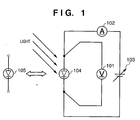
- a power supply 103 for supplying power to a cell 104 or 105 shown in Fig. 1 e.g., a bipolar power supply capable of changing the voltage is used. If the voltage to be applied to the cell 104 or 105 can be changed or swept, a known means such as an electronic load or discharge of charges accumulated in a capacitor can be used in place of the power supply 103.
- the spectrum of irradiation light must be measured.
- a known spectroradiometer is preferably used.
- a measurement control and data processing section such as a personal computer is preferably used.
- Fig. 19 is a flow chart showing the measurement procedure of this embodiment.
- the irradiance of irradiation light is measured or adjusted by the irradiance detector (S1).
- the current vs. voltage characteristic of the reference cell is measured (S2), and the current vs. voltage characteristic of the sample cell is measured (S3). That is, while changing the voltage to be applied to the object to be measured, the voltage applied and current supplied to the object to be measured are measured, thereby obtaining the current vs. voltage characteristics.
- Steps S2 and S3 are preferably executed at least within a short time.
- the current vs. voltage characteristic of the reference cell in the standard test conditions is compared with the measurement result of the current vs. voltage characteristic of the reference cell, thereby obtaining a shift of the measurement result from the standard test condition on the basis of the shift of the irradiation light from the standard test condition (S4).
- the measurement result of the current vs. voltage characteristic of the sample cell is corrected (S5), and the photoelectric conversion characteristics of the sample cell are obtained (S6).
- a-Si amorphous silicon
- a-SiGe amorphous silicon germanium
- the triple solar cell had a size of about 1 cm ⁇ 1 cm formed on a single stainless steel substrate and was in a single unit state before cells were connected in series or in parallel. No surface protective layer was formed.
- the solar simulator had an effective irradiation area of about 10 cm ⁇ 10 cm.
- the time variation ratio of the irradiance was ⁇ 1% or less, and the positional variation in irradiance was ⁇ 2% or less.
- a power supply 103 a known bipolar power supply was used.
- the voltage was swept by a personal computer.
- voltage and current detectors 101 and 102 a known digital multi-meter was used, and the data of the measured voltage and current were obtained by the personal computer. With the above arrangement, the current vs. voltage characteristic of the cell was acquired.
- the reference cell As the reference cell, a triple solar cell having the same structure and same size as those of the sample cell was used, which had been irradiated with light from the solar simulator for 1,000 hrs and degraded to stabilize the characteristic change over time in advance.
- the current vs. voltage characteristic of the reference cell in the standard test conditions was measured in advance by the multi-source method. When the characteristics of the reference cell are stabilized, the characteristics of the reference cell do not change even when it is irradiated with light in measurement, and an accurate measurement result can be obtained. In addition, the time interval of re-measurement of the current vs. voltage characteristic of the reference cell in the standard test conditions can be increased.
- a copper block and Peltier element were arranged on the lower surface of the stainless steel substrate of each of the sample cell and reference cell to adjust the cell temperature to 25°C ⁇ 1°C.
- this example corresponds to the case described above about the correction method wherein "the irradiance can be adjusted". Since the irradiance and cell temperature were adjusted to 1,000 W/m 2 and 25°C, irradiance correction and temperature correction for the obtained current vs. voltage characteristic were unnecessary.
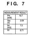
- a maximum power Pm.s* was obtained from the current vs. voltage characteristic of the sample cell
- FF.r* was obtained from the current vs. voltage characteristic of the reference cell
- FF.r.o was obtained from the current vs. voltage characteristic of the reference cell in the standard test conditions, which was measured in advance, and correction was performed by equation (9) to obtain a maximum power Pm.s.o.
- Fig. 5 shows the results.
- Fig. 6 also shows results obtained by measuring the spectrum of the solar simulator by a known spectroradiometer and calculating the mismatch coefficient by equation (6).
- the component cell for limiting the current in the entire triple solar cell is the top cell.
- the ratio of the short-circuit currents of the component cells in the sample cell and reference cell falls within the range of ⁇ 10%.
- the mismatch coefficient of each component cell of the sample cell with respect to the reference cell in light irradiation is 0.99 to 1.00.
- the reference cell has a spectral response approximate to that of the sample cell and the same currrent-limiting cell as that of the sample cell, and the mismatch coefficient is almost 1, the accuracy of the correction results for the output characteristics of the sample cell improves.
- Example 1 To verify the accuracy of the measurement results of Example 1 described above, the sample cell of Example 1 was measured by the multi-source method.
- the spectrum of the solar simulator was adjusted such that the current of each of the top cell, middle cell, and bottom cell of the sample cell equaled the value in the standard test conditions.
- the spectrum of the solar simulator at this time was measured using a known spectroradiometer.
- Example 7 shows the measurement results.
- Fig. 8 shows results obtained by dividing the results of Example 1 before and after correction by the values shown in Fig. 7 and representing the increase/decrease in each value by percentage.
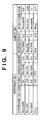
- Fig. 9 shows results obtained by correcting the measurement results not by equation (9) but by equation (10).
- Fig. 10 shows results obtained by dividing the results of Example 2 before and after correction shown in Fig. 9 by the values shown in Fig. 7 and representing the increase/decrease in each value by percentage. As is apparent from the results shown in Fig. 10, even with the measuring method of this embodiment using equation (10), accurate measurement results almost the same as those by the multi-source method can be obtained.
- ⁇ c-Si micro-crystallite silicon
- the double solar cell was a submodule which had a size of about 25 cm ⁇ 18 cm formed on a single stainless steel substrate and was in a single unit state before submodules were connected in series or in parallel. No surface protective layer was formed.
- the solar simulator had an effective irradiation area of about 130 cm ⁇ 80 cm. The positional variation in irradiance was ⁇ 3% or less, and the positional variation in irradiance within the area of the submodule was ⁇ 1.5% or less.
- a power supply 103 As a power supply 103, a known electronic load was used. The voltage was swept by a personal computer. As voltage and current detectors 101 and 102, a combination of a resistor and analog-digital conversion card was used, and the data of the measured voltage and current were obtained by the personal computer. With the above arrangement, the current vs. voltage characteristic of the submodule was acquired.
- the reference submodule As the reference submodule, a double solar cell submodule having the same structure and same size as those of the sample submodule was used, which had been irradiated with light from the solar simulator for 1,000 hrs and degraded to stabilize the characteristic change over time in advance.
- the current vs. voltage characteristic of the reference submodule was measured outdoors in advance when sunlight satisfied the standard sunlight conditions or equivalent meteorological conditions, and the irradiance and temperature were corrected, thereby obtaining the current vs. voltage characteristic in the standard test conditions.
- the temperature of the sample submodule was 27°C and the temperature of the reference submodule was 27.5°C.
- the current vs. voltage characteristics of the two submodules were corrected by temperature correction coefficients that were obtained using a double solar cell having the same structure as described above in advance.
- a maximum power Pm.s* was obtained from the corrected current vs. voltage characteristic of the sample submodule
- FF.r* was obtained from the corrected current vs. voltage characteristic of the reference submodule
- FF.r.o was obtained from the current vs. voltage characteristic of the reference submodule in the standard test conditions, which was measured in advance, and correction was performed by equation (9) to obtain a maximum power Pm.s.o.
- Fig. 11 shows the results.
- the current vs. voltage characteristic of the sample submodule was measured outdoors when sunlight satisfied the standard sunlight conditions or equivalent meteorological conditions, and the irradiance and temperature were corrected, thereby acquiring the current vs. voltage characteristic in the standard test conditions.
- the output characteristics Pm, Voc, Isc, and FF obtained from the results were compared with the output characteristics in measurement and after correction shown in Fig. 11.
- Fig. 12 shows the comparison results.
- the double solar cell module was a so-called super straight module having a size of about 95 cm ⁇ 55 cm in which 15 serial ⁇ 3 parallel double solar cells each formed on a single-crystal silicon wafer with a size of about 10 cm ⁇ 10 cm were connected.
- the outdoor measurement was executed on a fine day when the angle of incidence direct sunlight was 10° or less and the irradiance was 800 W/m 2 or more. Since the measurement was executed not under limited meteorological conditions for the standard sunlight method but under more general meteorological conditions, the spectrum of sunlight did not satisfy the conditions of standard sunlight.
- a power supply 103 a known electronic load was used. The voltage was swept by the function of the electronic load.
- voltage and current detectors 101 and 102 a known digital multi-meter was used, and the data of the measured voltage and current were acquired by a notebook-type personal computer. With the above arrangement, the current vs. voltage characteristic of the module was acquired.
- a double solar cell submodule having the same module structure and a size of about 10 cm ⁇ 10 cm was used, which had been irradiated with light from a solar simulator for 1,000 hrs and degraded to stabilize the characteristic change over time in advance.
- the current vs. voltage characteristic of the reference module in the standard test conditions was measured in advance by the multi-source method.
- any error in temperature correction and any measurement error in output characteristics are reduced.
- the reference module and sample module were installed on the same plane of the same frame, the angles of incidence of direct sunlight were equalized, and the current vs. voltage characteristics were simultaneously measured, thereby equalizing the measurement conditions.
- the reference module As a irradiance detector, the reference module was used. The irradiance was measured by the short-circuit current of the reference module.
- the temperature of the sample module was calculated on the basis of the temperature coefficient from an open-circuit voltage Voc measured indoors using a pulse-type solar simulator while controlling the temperature to 25°C and the open-circuit voltage Voc measured outdoors.
- the temperature of the reference module was also calculated on the basis of the temperature coefficient from the open-circuit voltage Voc measured indoors using the multi-source method while controlling the temperature to 25°C and the open-circuit voltage Voc measured outdoors. After that, temperature correction and irradiance correction were executed for the current vs. voltage characteristics of the two modules on the basis of the temperature correction coefficient values and series resistance values obtained using a double solar cell having the same structure as described above.
- a maximum power Pm.s* was obtained from the current vs. voltage characteristic of the sample module after temperature correction and irradiance correction
- FF.r* was obtained from the current vs. voltage characteristic of the reference module after temperature and irradiance corrections
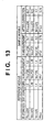
- FF.r.o was obtained from the current vs. voltage characteristic of the reference module in the standard test conditions, which was measured in advance, and correction was performed by equation (7) to obtain a maximum power Pm.s.o.
- the resultant value was the same as that obtained using equation (7).
- Fig. 13 shows the results.
- the current vs. voltage characteristic of the sample module was measured outdoors when sunlight satisfied the standard sunlight conditions or equivalent meteorological conditions, and the irradiance and temperature were corrected, thereby acquiring the current vs. voltage characteristic in the standard test conditions.
- the output characteristics Pm, Voc, Isc, and FF obtained from the results were compared with the output characteristics in measurement and after correction shown in Fig. 13.
- Fig. 14 shows the comparison results.
- the meteorological conditions suitable for the standard sunlight method can be obtained in only several days a year.
- the measurements can be executed any number of times a day as far as a irradiance of 800 W/m 2 or more is obtained on a fine day, and the number of days when the outdoor measurement is possible can be largely increased.
- a triple solar cell identical to that of Example 1 was formed on a single stainless steel substrate having a size of about 25 cm ⁇ 35 cm to prepare a submodule.
- Five submodules were connected in series using a zinc-plated steel sheet as a support, and a surface protective layer, bypass diode, junction box, and the like were added to form a roofing-material-shaped module having a size of about 140 cm ⁇ 42 cm.
- Twenty modules were connected in series to form a string, and five strings are connected in parallel to form a solar cell array.
- the output of the solar cell array was 3.2 kW.
- This solar cell array also functions as a roofing material and is installed as the roof of a building and connected to a power conditioner such as an inverter through a connection box so as to function as part of a photovoltaic power generation system.
- the output characteristics of the solar cell array that was kept installed on the roof were measured by sunlight.
- the measurement was executed on a fine day when the angle of incidence of direct sunlight was 10° or less and the irradiance was 800 W/m 2 or more. Since the measurement was executed not under limited meteorological conditions for the standard sunlight method but under more general meteorological conditions, the spectrum of sunlight did not satisfy the conditions of standard sunlight.
- the output from the solar cell array was connected to a power supply 103.
- a known method of discharging electric charges accumulated in a capacitor was used. The voltage was swept by discharging the capacitor.
- voltage and current detectors 101 and 102 a known digital multi-meter was used, and the data of the measured voltage and current were obtained by a notebook-type personal computer. With the above arrangement, the current vs. voltage characteristic of the solar cell array was acquired.
- a triple solar cell submodule having the same module structure as that of the sample and a size of about 25 cm ⁇ 35 cm was used, which had been degraded by injecting a current for 1,500 hrs by a known forward bias current injection method to stabilize the characteristic change over time in advance.
- the current vs. voltage characteristic of the reference module in the standard test conditions was measured in advance by the standard sunlight method.
- any error in temperature correction and any measurement error in output characteristics are reduced.
- the reference module and the solar cell array as the sample were set at the same angle with respect to sunlight to equalize the angles of incidence of direct sunlight, and the current vs. voltage characteristics were simultaneously measured, thereby equalizing the measurement conditions.
- the reference module As a irradiance detector, the reference module was used. The irradiance was measured by the short-circuit current of the reference module.
- the temperature of the solar cell array was obtained by weighted-averaging temperatures measured at a plurality of points by a radiation thermometer from the array surface side at an estimated angle that generated no shadow on the array.
- the temperature of the reference module was measured by a sheet-type thermocouple of copper constantan and a digital thermometer, which were bonded to the almost central portion of the lower surface of the module. After that, temperature correction and irradiance correction were executed for the current vs. voltage characteristics of the module and the array on the basis of the temperature correction coefficient values and series resistance values obtained using a triple solar cell having the same structure as described above. In addition, the degree of dirt on the solar cell array was estimated, and the current vs. voltage characteristic was corrected using a dirt correction coefficient.
- a maximum power Pm.s* was obtained from the current vs. voltage characteristic of the solar cell array after temperature correction, irradiance correction, and dirt correction
- FF.r* was obtained from the current vs. voltage characteristic of the reference module after temperature correction and irradiance correction
- FF.r.o was obtained from the current vs. voltage characteristic of the reference module in the standard test conditions, which was measured in advance, and correction was performed by equation (7) to obtain a maximum power Pm.s.o.
- Fig. 15 shows the results.
- the output characteristics of a photosensor having a stacked structure including a top cell with a pn junction by AlGaAs and a bottom cell with a pn junction by GaAs were measured by a known solar simulator using a metal halide lamp as a light source.
- the photosensor was formed on a single GaAs wafer and then cut into a size of about 1 cm ⁇ 1 cm and was in a state before a sensor unit was formed.
- the solar simulator had an effective irradiation area of about 10 cm ⁇ 10 cm.
- the time variation ratio of the irradiance was ⁇ 1% or less, and the positional variation in irradiance was ⁇ 2% or less.
- a power supply 103 As a power supply 103, a known electronic load was used. The voltage was swept by a personal computer. As voltage and current detectors 101 and 102, a combination of a resistor and analog-digital conversion card was used, and the data of the measured voltage and current were acquired by the personal computer. With the above arrangement, the current vs. voltage characteristic of the photosensor was acquired.
- the reference cell 100 stacked photosensors having the same size were prepared, and one photosensor having average output characteristics and spectral response was selected therefrom and used.
- the current vs. voltage characteristic of the reference cell in the standard test conditions was measured in advance by the multi-source method.
- the reference cell As a irradiance detector, the reference cell was used, and the irradiance of the solar simulator was adjusted to 1,000 W/m 2 such that the maximum power of the reference cell matched that in the standard test conditions, i.e., the above-described equation (11) of the correction method is satisfied.
- a copper block and Peltier element were arranged on the lower surface of the substrate to adjust the temperatures of the sample and reference cells to 25°C ⁇ 1°C.
- this example corresponds to the above-described case wherein the irradiance can be adjusted. Since the irradiance and the temperatures of the cell and sample were adjusted to 1,000 W/m 2 and 25°C, irradiance correction and temperature correction for the obtained current vs. voltage characteristic were unnecessary.
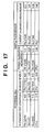
- Fig. 17 shows the measurement results in the column of current calibration measurement.
- the current vs. voltage characteristic of the photosensor in the standard test conditions was measured by the multi-source method.
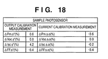
- the output characteristics Pm, Voc, Isc, and FF obtained from the results were compared with the output characteristics in power calibration measurement and current calibration measurement shown in Fig. 17.
- Fig. 18 shows the comparison results.
- the power calibration measurement of this example is a simple measurement process, the time required for measurement is shortened, and a number of samples can be measured within a short time. Hence, this method is suitable for an inspection system of a manufacturing line, which must automatically measure a number of samples.
- the output characteristics of a stacked photoelectric conversion device can be accurately measured.
- an equivalent measurement accuracy can be obtained without using any expensive measuring apparatus, unlike the multi-source method, the cost can be reduced.
- an equivalent measurement accuracy can be obtained, and the measurement can be facilitated.
- a semiconductor junction for limiting the short-circuit current of the stacked photoelectric conversion device in light irradiation is defined as a current-limiting cell
- the degree of approximation for spectral response between the stacked photoelectric conversion device to be tested and a stacked photoelectric conversion device as a reference improves because the current-limiting cells are formed from the same semiconductor junction between test and reference devices, error in short-circuit current and fill factor is reduced, and the measurement accuracy for the output characteristics of the stacked photoelectric conversion device can be improved.
- the light-receiving area of the solar cell to be measured is limited to the minimal area of laboratory level, and it is hard to measure a cell, module, or array having an area more than 400 cm 2 .
- the irradiance of irradiation light is measured or adjusted, the current vs. voltage characteristic of a reference cell is measured, and the current vs. voltage characteristic of a sample cell is measured.
- the current vs. voltage characteristic of the reference cell in standard test conditions is compared with the measurement result of the current vs.
- the measurement result of the current vs. voltage characteristic of the sample cell is corrected, and the photoelectric conversion characteristics of the sample cell are obtained.
Landscapes
- Physics & Mathematics (AREA)
- Engineering & Computer Science (AREA)
- Health & Medical Sciences (AREA)
- Computer Vision & Pattern Recognition (AREA)
- Electromagnetism (AREA)
- Toxicology (AREA)
- General Engineering & Computer Science (AREA)
- General Physics & Mathematics (AREA)
- Photovoltaic Devices (AREA)
- Testing Of Individual Semiconductor Devices (AREA)
- Testing Or Measuring Of Semiconductors Or The Like (AREA)
Applications Claiming Priority (2)
| Application Number | Priority Date | Filing Date | Title |
|---|---|---|---|
| JP2000202358 | 2000-07-04 | ||
| JP2000202358 | 2000-07-04 |
Publications (3)
| Publication Number | Publication Date |
|---|---|
| EP1170596A2 true EP1170596A2 (de) | 2002-01-09 |
| EP1170596A3 EP1170596A3 (de) | 2006-01-04 |
| EP1170596B1 EP1170596B1 (de) | 2007-11-21 |
Family
ID=18699892
Family Applications (1)
| Application Number | Title | Priority Date | Filing Date |
|---|---|---|---|
| EP01116098A Expired - Lifetime EP1170596B1 (de) | 2000-07-04 | 2001-07-03 | Verfahren und Vorrichtung zur Messung von photoelektrischen Umwandlungscharakteristiken |
Country Status (4)
| Country | Link |
|---|---|
| US (1) | US6876187B2 (de) |
| EP (1) | EP1170596B1 (de) |
| CN (1) | CN1199255C (de) |
| DE (1) | DE60131499D1 (de) |
Cited By (7)
| Publication number | Priority date | Publication date | Assignee | Title |
|---|---|---|---|---|
| ES2212891A1 (es) * | 2002-07-12 | 2004-08-01 | Universidad Del Pais Vasco Euskal Herrijo Uniberstsitatea | Sistema de evaluacion de celulas solares. |
| WO2011033025A1 (de) * | 2009-09-16 | 2011-03-24 | Oerlikon Solar Ag, Trübbach | Verfahren und anordnung zum einstellen eines solarsimulators |
| WO2011041819A3 (de) * | 2009-10-09 | 2011-07-28 | Fronius International Gmbh | Verfahren und vorrichtung zur fehlererkennung in einer photovoltaik-anlage |
| EP2355164A1 (de) * | 2008-11-19 | 2011-08-10 | Konica Minolta Sensing, Inc. | Vorrichtung zur überprüfung einer solarbatterie und verfahren zur überprüfung einer solarbatterie |
| CN102854447A (zh) * | 2012-09-07 | 2013-01-02 | 倪峰 | 便携光伏组件功率测试仪器及其测试方法 |
| RU2476958C2 (ru) * | 2011-03-17 | 2013-02-27 | Закрытое Акционерное Общество "ТЕЛЕКОМ-СТВ" | Способ определения вольтамперных характеристик солнечных элементов на симуляторе солнечного излучения |
| WO2016174150A1 (de) * | 2015-04-30 | 2016-11-03 | Fronius International Gmbh | Verfahren zum prüfen der stränge an solarmodulen einer photovoltaikanlage und photovoltaik-wechselrichter zur durchführung des verfahrens |
Families Citing this family (35)
| Publication number | Priority date | Publication date | Assignee | Title |
|---|---|---|---|---|
| US6541754B2 (en) * | 2000-07-05 | 2003-04-01 | Canon Kabushiki Kaisha | Method and apparatus for measuring photoelectric conversion characteristics of photoelectric conversion device |
| TWI227806B (en) * | 2002-05-30 | 2005-02-11 | Fujitsu Display Tech | Substrate for liquid crystal display, liquid crystal display having the same, and method of manufacturing the same |
| DE10240083A1 (de) * | 2002-08-30 | 2004-03-11 | Austriamicrosystems Ag | Verfahren zur Kalibrierung einer Fotodiode, Halbleiterchip und Betriebsverfahren |
| CN100357755C (zh) * | 2004-04-22 | 2007-12-26 | 上海交通大学 | 太阳能电池有效扩散长度的测试方法 |
| JP5236858B2 (ja) * | 2005-02-01 | 2013-07-17 | 日清紡ホールディングス株式会社 | 太陽電池の出力特性の測定方法。 |
| JP5148073B2 (ja) * | 2005-06-17 | 2013-02-20 | 日清紡ホールディングス株式会社 | ソーラシミュレータによる測定方法 |
| US8072587B2 (en) | 2006-01-20 | 2011-12-06 | Newport Corporation | Machine and method for measuring a characteristic of an optical signal |
| US7906980B1 (en) * | 2008-02-19 | 2011-03-15 | William Ray Cravey | Rapid sweeping load testing circuit and method |
| US8037327B2 (en) * | 2008-03-31 | 2011-10-11 | Agilent Technologies, Inc. | System and method for improving dynamic response in a power supply |
| CN101299054B (zh) * | 2008-05-23 | 2010-12-08 | 南京大学 | 染料敏化纳米薄膜太阳能电池i-v特性和转换效率特性的测量方法 |
| JP2009283845A (ja) * | 2008-05-26 | 2009-12-03 | Npc Inc | 太陽電池出力特性評価装置および太陽電池出力特性評価方法 |
| US8378661B1 (en) * | 2008-05-29 | 2013-02-19 | Alpha-Omega Power Technologies, Ltd.Co. | Solar simulator |
| GB0821146D0 (en) | 2008-11-19 | 2008-12-24 | Univ Denmark Tech Dtu | Method of testing solar cells |
| TWI379424B (en) * | 2009-10-30 | 2012-12-11 | Atomic Energy Council | Measurement apparatus of temperature coefficients for concentrator photovoltaic module |
| JP5328041B2 (ja) * | 2009-12-01 | 2013-10-30 | 日清紡メカトロニクス株式会社 | ソーラシミュレータ及びソーラシミュレータによる測定方法 |
| JP5660127B2 (ja) * | 2010-03-15 | 2015-01-28 | コニカミノルタ株式会社 | ソーラシミュレータの光量評価装置、および、ソーラシミュレータの光量評価方法 |
| TWI397708B (zh) * | 2010-04-06 | 2013-06-01 | Ind Tech Res Inst | 太陽能電池之量測系統和太陽光模擬器 |
| TWI400459B (zh) * | 2010-06-23 | 2013-07-01 | Nat Univ Tsing Hua | 一種太陽能電池參數之萃取方法 |
| JP5562762B2 (ja) * | 2010-08-20 | 2014-07-30 | 株式会社東芝 | 開放電圧制御システム |
| JP5732873B2 (ja) | 2011-01-31 | 2015-06-10 | 株式会社日立製作所 | 太陽電池の特性演算方法及び太陽光発電システム |
| CN102253345A (zh) * | 2011-06-04 | 2011-11-23 | 南昌航空大学 | 一种利用电致荧光强度测量太阳电池理想因子的装置及方法 |
| EP2727155B1 (de) * | 2011-06-28 | 2019-08-07 | (CNBM) Bengbu Design & Research Institute for Glass Industry Co., Ltd. | Verfahren zur schnellen stabilisierung der nennleistung eines dünnschichtsolarmoduls |
| CN102508463A (zh) * | 2011-09-22 | 2012-06-20 | 李旭东 | 一种可优化控制的新能源实验室系统 |
| US20130194564A1 (en) * | 2012-01-26 | 2013-08-01 | Solarworld Industries America, Inc. | Method and apparatus for measuring photovoltaic cells |
| CN102621475B (zh) * | 2012-04-17 | 2014-09-24 | 保定维特瑞光电能源科技有限公司 | 太阳能光伏电池检测装置 |
| CN102707241A (zh) * | 2012-06-07 | 2012-10-03 | 成都聚合科技有限公司 | 便携光源功率表测试带散热器光电转换接收器模块装置 |
| CN102778643B (zh) * | 2012-07-12 | 2014-10-29 | 华中科技大学 | 用于测量光伏太阳能电池光电转换特性参数的设备及方法 |
| DE102013100593B4 (de) * | 2013-01-21 | 2014-12-31 | Wavelabs Solar Metrology Systems Gmbh | Verfahren und Vorrichtung zum Vermessen von Solarzellen |
| CN103344899B (zh) * | 2013-06-28 | 2016-01-13 | 苏州阿特斯阳光电力科技有限公司 | 一种背接触太阳电池的光电伏安特性参数的标定方法 |
| JP6209412B2 (ja) * | 2013-09-27 | 2017-10-04 | 株式会社日立製作所 | 太陽光発電システムの故障診断システム及び故障診断方法 |
| CN104638051B (zh) * | 2013-11-06 | 2017-06-20 | 恒基伟业知识产权管理顾问(北京)有限公司 | 一种加速稳定碲化镉薄膜太阳能模块最大功率的方法 |
| US10040660B1 (en) | 2017-07-17 | 2018-08-07 | Gpcp Ip Holdings Llc | Power device for a product dispenser |
| CN107748303A (zh) * | 2017-09-15 | 2018-03-02 | 西藏自治区能源研究示范中心 | 一种移动式光伏器件电性能测试系统 |
| CN111384895A (zh) * | 2018-12-27 | 2020-07-07 | 东泰高科装备科技有限公司 | 太阳能电池测试系统及太阳能电池测试方法、存储介质 |
| CN112217474B (zh) * | 2020-09-14 | 2023-06-16 | 中电科蓝天科技股份有限公司 | 空间用三结砷化镓工作标准太阳电池的标定和使用方法 |
Citations (1)
| Publication number | Priority date | Publication date | Assignee | Title |
|---|---|---|---|---|
| EP0887652A2 (de) * | 1997-06-30 | 1998-12-30 | Canon Kabushiki Kaisha | Messeinrichtung und Verfahren zum Messen einer Solarzellencharakteristik |
Family Cites Families (4)
| Publication number | Priority date | Publication date | Assignee | Title |
|---|---|---|---|---|
| US4049963A (en) * | 1973-09-14 | 1977-09-20 | Coulter Information Systems, Inc. | Photoelectric measuring device |
| JPS57179674A (en) | 1981-04-28 | 1982-11-05 | Matsushita Electric Ind Co Ltd | Measuring method for output of solar cell |
| US4730158A (en) * | 1986-06-06 | 1988-03-08 | Santa Barbara Research Center | Electron-beam probing of photodiodes |
| JP2000243995A (ja) * | 1998-12-25 | 2000-09-08 | Canon Inc | 太陽電池モジュールの検査方法及び製造方法 |
-
2001
- 2001-06-28 US US09/892,704 patent/US6876187B2/en not_active Expired - Fee Related
- 2001-07-03 DE DE60131499T patent/DE60131499D1/de not_active Expired - Lifetime
- 2001-07-03 EP EP01116098A patent/EP1170596B1/de not_active Expired - Lifetime
- 2001-07-04 CN CNB011221313A patent/CN1199255C/zh not_active Expired - Fee Related
Patent Citations (1)
| Publication number | Priority date | Publication date | Assignee | Title |
|---|---|---|---|---|
| EP0887652A2 (de) * | 1997-06-30 | 1998-12-30 | Canon Kabushiki Kaisha | Messeinrichtung und Verfahren zum Messen einer Solarzellencharakteristik |
Non-Patent Citations (3)
| Title |
|---|
| EMERY K: "The rating of photovoltaic performance" IEEE TRANSACTIONS ON ELECTRON DEVICES IEEE USA, vol. 46, no. 10, October 1999 (1999-10), pages 1928-1931, XP002350133 ISSN: 0018-9383 * |
| GLATFELTER T ET AL: "A method for determining the conversion efficiency of multiple-cell photovoltaic devices" 4 May 1987 (1987-05-04), CONFERENCE RECORD OF THE NINETEENTH IEEE PHOTOVOLTAIC SPECIALISTS CONFERENCE - 1987 (CAT. NO.87CH2400-0) IEEE NEW YORK, NY, USA, PAGE(S) 1187 - 1193 , XP009055414 * abstract; figures 2-4 * * pages 1190-119, column 2 * * |
| HEIDLER K ET AL COMMISSION OF THE EUROPEAN COMMUNITIES: "MEASUREMENT OF MULTI-JUNCTION SOLAR CELLS" 10TH. E.C. PHOTOVOLTAIC SOLAR ENERGY CONFERENCE. LISBON, PORTUGAL, APRIL 8 - 12, 1991, PROCEEDINGS OF THE INTERNATIONAL PHOTOVOLTAIC SOLAR ENERGY CONFERENCE, DORDRECHT, KLUWER ACADEMIC PUBLISHERS, NL, vol. CONF. 10, 8 April 1991 (1991-04-08), pages 111-114, XP001135640 ISBN: 0-7923-1389-5 * |
Cited By (12)
| Publication number | Priority date | Publication date | Assignee | Title |
|---|---|---|---|---|
| ES2212891A1 (es) * | 2002-07-12 | 2004-08-01 | Universidad Del Pais Vasco Euskal Herrijo Uniberstsitatea | Sistema de evaluacion de celulas solares. |
| EP2355164A1 (de) * | 2008-11-19 | 2011-08-10 | Konica Minolta Sensing, Inc. | Vorrichtung zur überprüfung einer solarbatterie und verfahren zur überprüfung einer solarbatterie |
| EP2355164A4 (de) * | 2008-11-19 | 2014-03-26 | Konica Minolta Sensing Inc | Vorrichtung zur überprüfung einer solarbatterie und verfahren zur überprüfung einer solarbatterie |
| US8918298B2 (en) | 2008-11-19 | 2014-12-23 | Konica Minolta Sensing, Inc. | Solar cell evaluation device and solar cell evaluation method |
| WO2011033025A1 (de) * | 2009-09-16 | 2011-03-24 | Oerlikon Solar Ag, Trübbach | Verfahren und anordnung zum einstellen eines solarsimulators |
| WO2011041819A3 (de) * | 2009-10-09 | 2011-07-28 | Fronius International Gmbh | Verfahren und vorrichtung zur fehlererkennung in einer photovoltaik-anlage |
| US9553215B2 (en) | 2009-10-09 | 2017-01-24 | Fronius International Gmbh | Method and device for recognizing faults in a photovoltaic system |
| RU2476958C2 (ru) * | 2011-03-17 | 2013-02-27 | Закрытое Акционерное Общество "ТЕЛЕКОМ-СТВ" | Способ определения вольтамперных характеристик солнечных элементов на симуляторе солнечного излучения |
| CN102854447A (zh) * | 2012-09-07 | 2013-01-02 | 倪峰 | 便携光伏组件功率测试仪器及其测试方法 |
| CN102854447B (zh) * | 2012-09-07 | 2014-10-22 | 倪峰 | 便携光伏组件功率测试仪器及其测试方法 |
| WO2016174150A1 (de) * | 2015-04-30 | 2016-11-03 | Fronius International Gmbh | Verfahren zum prüfen der stränge an solarmodulen einer photovoltaikanlage und photovoltaik-wechselrichter zur durchführung des verfahrens |
| AU2016256558B2 (en) * | 2015-04-30 | 2021-01-28 | Fronius International Gmbh | Method for testing the strings to solar modules of a photovoltaic system, and photovoltaic inverter for carrying out the method |
Also Published As
| Publication number | Publication date |
|---|---|
| EP1170596B1 (de) | 2007-11-21 |
| EP1170596A3 (de) | 2006-01-04 |
| US20020014886A1 (en) | 2002-02-07 |
| CN1199255C (zh) | 2005-04-27 |
| DE60131499D1 (de) | 2008-01-03 |
| US6876187B2 (en) | 2005-04-05 |
| CN1331488A (zh) | 2002-01-16 |
Similar Documents
| Publication | Publication Date | Title |
|---|---|---|
| US6876187B2 (en) | Method and apparatus for measuring photoelectric conversion characteristics | |
| US6541754B2 (en) | Method and apparatus for measuring photoelectric conversion characteristics of photoelectric conversion device | |
| US6946858B2 (en) | Method and apparatus for measuring photoelectric conversion device, and process and apparatus for producing photoelectric conversion device | |
| Emery | Measurement and characterization of solar cells and modules | |
| Muñoz-García et al. | Characterization of thin film PV modules under standard test conditions: Results of indoor and outdoor measurements and the effects of sunlight exposure | |
| Louwen et al. | Comprehensive characterisation and analysis of PV module performance under real operating conditions | |
| Dunn et al. | Comparison of pyranometers vs. PV reference cells for evaluation of PV array performance | |
| JP2006229063A (ja) | 光電変換素子の電流電圧特性測定結果の補正方法および予測方法、光電変換素子の測定方法および装置、光電変換素子の製造方法および装置 | |
| Hishikawa et al. | Precise outdoor PV module performance characterization under unstable irradiance | |
| JP2002111030A (ja) | 光電変換デバイスの、光電変換特性の測定または予測方法、および、スペクトル依存性の定量化方法、並びに、それらの装置 | |
| JP5013637B2 (ja) | 光電変換特性の測定方法およびその装置 | |
| Hishikawa et al. | Improved precision of the outdoor performance measurements of photovoltaic modules by using the photovoltaic irradiance sensor | |
| Ramgolam et al. | Modelling the impact of spectral irradiance and average photon energy on photocurrent of solar modules | |
| JP2005011958A (ja) | 光電変換素子の電流電圧特性の測定方法及び測定装置 | |
| Bliss et al. | Indoor measurement of photovoltaic device characteristics at varying irradiance, temperature and spectrum for energy rating | |
| Liu et al. | Indoor and outdoor comparison of CPV III–V multijunction solar cells | |
| JP4613053B2 (ja) | 多接合型光電変換素子試験セルの特性測定方法及び近似太陽光光源のスペクトル調整方法 | |
| Osterwald et al. | CPV multijunction solar cell characterization | |
| Shepovalova | PV systems photoelectric parameters determining for field conditions and real operation conditions | |
| JP6964904B2 (ja) | 光電変換素子の電流−電圧特性の推定方法、装置及びプログラム並びに特性推定装置 | |
| JP2004273870A (ja) | 積層型光電変換素子の測定方法および装置 | |
| Emery | Photovoltaic efficiency measurements | |
| Kurtz et al. | The effect of chromatic aberrations on two-junction, two-terminal, devices on a concentrator system [solar cells] | |
| WO2023191718A2 (en) | Apparatus for characterization of photovoltaic modules | |
| Schweiger et al. | Electrical stability of PV modules in different climates |
Legal Events
| Date | Code | Title | Description |
|---|---|---|---|
| PUAI | Public reference made under article 153(3) epc to a published international application that has entered the european phase |
Free format text: ORIGINAL CODE: 0009012 |
|
| AK | Designated contracting states |
Kind code of ref document: A2 Designated state(s): AT BE CH CY DE DK ES FI FR GB GR IE IT LI LU MC NL PT SE TR |
|
| AX | Request for extension of the european patent |
Free format text: AL;LT;LV;MK;RO;SI |
|
| PUAL | Search report despatched |
Free format text: ORIGINAL CODE: 0009013 |
|
| RIC1 | Information provided on ipc code assigned before grant |
Ipc: 7G 01R 31/26 B Ipc: 7G 01R 19/165 A Ipc: 7G 01R 31/308 B |
|
| AK | Designated contracting states |
Kind code of ref document: A3 Designated state(s): AT BE CH CY DE DK ES FI FR GB GR IE IT LI LU MC NL PT SE TR |
|
| AX | Request for extension of the european patent |
Extension state: AL LT LV MK RO SI |
|
| 17P | Request for examination filed |
Effective date: 20060704 |
|
| 17Q | First examination report despatched |
Effective date: 20060731 |
|
| AKX | Designation fees paid |
Designated state(s): DE FR GB IT NL |
|
| GRAP | Despatch of communication of intention to grant a patent |
Free format text: ORIGINAL CODE: EPIDOSNIGR1 |
|
| GRAS | Grant fee paid |
Free format text: ORIGINAL CODE: EPIDOSNIGR3 |
|
| GRAA | (expected) grant |
Free format text: ORIGINAL CODE: 0009210 |
|
| AK | Designated contracting states |
Kind code of ref document: B1 Designated state(s): DE FR GB IT NL |
|
| REG | Reference to a national code |
Ref country code: GB Ref legal event code: FG4D |
|
| REF | Corresponds to: |
Ref document number: 60131499 Country of ref document: DE Date of ref document: 20080103 Kind code of ref document: P |
|
| ET | Fr: translation filed | ||
| PLBE | No opposition filed within time limit |
Free format text: ORIGINAL CODE: 0009261 |
|
| STAA | Information on the status of an ep patent application or granted ep patent |
Free format text: STATUS: NO OPPOSITION FILED WITHIN TIME LIMIT |
|
| 26N | No opposition filed |
Effective date: 20080822 |
|
| PG25 | Lapsed in a contracting state [announced via postgrant information from national office to epo] |
Ref country code: DE Free format text: LAPSE BECAUSE OF FAILURE TO SUBMIT A TRANSLATION OF THE DESCRIPTION OR TO PAY THE FEE WITHIN THE PRESCRIBED TIME-LIMIT Effective date: 20080222 |
|
| PGFP | Annual fee paid to national office [announced via postgrant information from national office to epo] |
Ref country code: GB Payment date: 20120730 Year of fee payment: 12 |
|
| PGFP | Annual fee paid to national office [announced via postgrant information from national office to epo] |
Ref country code: IT Payment date: 20120711 Year of fee payment: 12 Ref country code: FR Payment date: 20120808 Year of fee payment: 12 |
|
| PGFP | Annual fee paid to national office [announced via postgrant information from national office to epo] |
Ref country code: NL Payment date: 20120716 Year of fee payment: 12 |
|
| REG | Reference to a national code |
Ref country code: NL Ref legal event code: V1 Effective date: 20140201 |
|
| GBPC | Gb: european patent ceased through non-payment of renewal fee |
Effective date: 20130703 |
|
| REG | Reference to a national code |
Ref country code: FR Ref legal event code: ST Effective date: 20140331 |
|
| PG25 | Lapsed in a contracting state [announced via postgrant information from national office to epo] |
Ref country code: GB Free format text: LAPSE BECAUSE OF NON-PAYMENT OF DUE FEES Effective date: 20130703 Ref country code: NL Free format text: LAPSE BECAUSE OF NON-PAYMENT OF DUE FEES Effective date: 20140201 |
|
| PG25 | Lapsed in a contracting state [announced via postgrant information from national office to epo] |
Ref country code: FR Free format text: LAPSE BECAUSE OF NON-PAYMENT OF DUE FEES Effective date: 20130731 Ref country code: IT Free format text: LAPSE BECAUSE OF NON-PAYMENT OF DUE FEES Effective date: 20130703 |