EP1170107A1 - Scheibenförmiges Trennwerkzeug - Google Patents
Scheibenförmiges Trennwerkzeug Download PDFInfo
- Publication number
- EP1170107A1 EP1170107A1 EP01810621A EP01810621A EP1170107A1 EP 1170107 A1 EP1170107 A1 EP 1170107A1 EP 01810621 A EP01810621 A EP 01810621A EP 01810621 A EP01810621 A EP 01810621A EP 1170107 A1 EP1170107 A1 EP 1170107A1
- Authority
- EP
- European Patent Office
- Prior art keywords
- base body
- cutting tool
- cutting
- tool according
- elongated holes
- Prior art date
- Legal status (The legal status is an assumption and is not a legal conclusion. Google has not performed a legal analysis and makes no representation as to the accuracy of the status listed.)
- Granted
Links
Images
Classifications
-
- B—PERFORMING OPERATIONS; TRANSPORTING
- B28—WORKING CEMENT, CLAY, OR STONE
- B28D—WORKING STONE OR STONE-LIKE MATERIALS
- B28D1/00—Working stone or stone-like materials, e.g. brick, concrete or glass, not provided for elsewhere; Machines, devices, tools therefor
- B28D1/02—Working stone or stone-like materials, e.g. brick, concrete or glass, not provided for elsewhere; Machines, devices, tools therefor by sawing
- B28D1/12—Saw-blades or saw-discs specially adapted for working stone
-
- B—PERFORMING OPERATIONS; TRANSPORTING
- B28—WORKING CEMENT, CLAY, OR STONE
- B28D—WORKING STONE OR STONE-LIKE MATERIALS
- B28D1/00—Working stone or stone-like materials, e.g. brick, concrete or glass, not provided for elsewhere; Machines, devices, tools therefor
- B28D1/02—Working stone or stone-like materials, e.g. brick, concrete or glass, not provided for elsewhere; Machines, devices, tools therefor by sawing
- B28D1/12—Saw-blades or saw-discs specially adapted for working stone
- B28D1/124—Saw chains; rod-like saw blades; saw cables
Definitions
- the invention relates to a disc-shaped cutting tool according to the preamble of Claim 1.
- wall slot devices For the production of slots in an underground, in which electrical flush lines can be installed, wall slot devices are used, at least have two spaced, disc-shaped cutting tools. The distance of the two cutting tools depends on the width of the one to be manufactured Slit. With the help of these separating tools, two are spaced apart Slits created in the underground. Then use a suitable stripping tool the web from the subsurface remaining between the slots broken, so that a channel is formed in the at least one electrical flush line is relocatable.
- disc-shaped cutting tools are used Application as they are known for example from DE-42 43 480. That in this known document described, disc-shaped separating tool has a disc-shaped base body, which with the help of a central mounting hole a receiving flange of the wall slot device can be fixed. The body instructs its circumferential area on several circular cutting areas, each by a recess open to the outer contour of the base body is interrupted.
- the base body also has several radial ones Direction extending slots, each slot in a portion of the Base body is arranged, each of two recesses and the central receiving bore is limited.
- the invention has for its object to a disc-shaped cutting tool create with which the removed material to be cut can be removed well and safely can, without causing thermal overloading of the cutting tool comes.
- the elongated holes according to the invention which are not only in the radial direction but also extend partially in the circumferential direction, form closely consecutive in the circumferential direction Air entry areas through which the air flows essentially without interruption reach a large amount of the space formed by the two separating tools can.
- the large amount of air that can be supplied for the removal of the material to be cut causes particularly good cooling of the cutting tools.
- a particularly good air circulation and thus a good removal of the removed Material to be cut from that formed by both disc-shaped cutting tools Gap is preferably achieved by having one in the middle area opposite the longitudinal extent of the elongated hole tangent to the beam a radial extends at an angle of 7 ° to 15 °.
- Particularly good discharge properties are achieved with an angle of 11 °.
- Expediently are in at least one of two recesses and the receiving bore limited, section of the base body at least two elongated holes arranged. This allows an even larger amount of air in the cutting tools inflow formed space flow, the removal of the material to be cut supports and contributes to improved cooling of the cutting tools.
- the two elongated holes are advantageously the same large educated.
- it is preferably in the circumferential direction measured distance between the two elongated holes within a section smaller than a shortest distance between two elongated holes adjacent to each other Cutouts.
- the accumulation of cut material in the recesses of the base body is expediently prevented in that the circumferential direction of the base body Measured width of the recesses towards the central mounting hole increases. Cuttings that are, for example, in the mouth area of the recesses accumulates, becomes more, worn, penetrating into the recesses Material to be cut in the radial direction into an enlarged area of the recesses pressed. In this extended area, the material to be cut no longer finds a hold and falls from the recesses.
- the cutting areas of the cutting tool are, for example, one peripheral area of the base body, which is coated with diamond grain.
- the cutting areas but can also be made from individual, from diamond grain and matrix material Shaped, segment-shaped cutting bodies can be formed, for example, by Soldering, welding or the like attached to the outer contour of the base body are.
- the elongated holes can also be designed such that they are separated from one another are, but overlap in the circumferential direction of the base body 1.
- the invention is based on a drawing that shows an embodiment, explained in more detail.
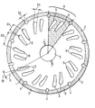
- the disk-shaped separating tool shown has a base body 1 with a central mounting hole 3.
- the wall thickness of the base body 1, not shown is between 1 mm and 3 mm.
- the base body 1 has a plurality of peripheral regions cutting segments 2 in the form of annular segments. These are cutting areas in the circumferential direction 2 separated from each other by a recess 4 leading to the outer contour of the base body 1 is open and the cutting area in the radial direction 2 enforced.
- the width S2 of these recesses measured perpendicular to the circumferential direction 4 increases towards the central receiving bore 3 and the bottom this recesses 4 is semicircular.
- a of the base body 1 are two elongated holes of the same size 5, which are arranged side by side in the circumferential direction.
- the two end areas these elongated holes 5 are essentially semicircular.
- a Width S1 of these elongated holes 5 increases towards the outer contour of the green body 1.
- each this elongated holes 5 extends along a portion of one from the center of the Base body 1 outgoing, spiral beam and is opposite a radial R arranged at an angle of 11 °.
Landscapes
- Engineering & Computer Science (AREA)
- Mining & Mineral Resources (AREA)
- Mechanical Engineering (AREA)
- Processing Of Stones Or Stones Resemblance Materials (AREA)
- Treatment Of Fiber Materials (AREA)
- Polishing Bodies And Polishing Tools (AREA)
- Harvester Elements (AREA)
- Perforating, Stamping-Out Or Severing By Means Other Than Cutting (AREA)
Abstract
Description
Claims (7)
- Trennwerkzeug mit einem, eine zentrale Aufnahmebohrung (3) aufweisenden, scheibenförmigen Grundkörper (1), wobei der Grundkörper (1) an seinem Umfangsbereich mehrere kreisringsegmentförmige Schneidbereiche (2) aufweist, die in Umfangsrichtung durch jeweils eine zur Aussenkontur des Grundkörpers (1) hin offen ausgebildete, in radialer Richtung den Schneidbereich (2) durchsetzende Ausnehmung (4) unterbrochen sind und der Grundkörper (1) in Ausschnitten (A), die von zwei Ausnehmungen (4) sowie der zentralen Aufnahmebohrung (3) begrenzt sind, jeweils zumindest ein sich im wesentlichen in radialer Richtung erstreckendes Langloch (5) aufweist, dadurch gekennzeichnet, dass sich das Langloch (5) entlang eines Abschnittes eines vom Zentrum des Grundkörpers (1) ausgehenden, spiralförmigen Strahles erstreckt.
- Trennwerkzeug nach Anspruch 1, dadurch gekennzeichnet, dass sich im mittleren Bereich der Längserstreckung des Langloches (5) eine am Strahl anliegende Tangente gegenüber einer Radialen (R) unter einem Winkel (W) von 7° bis 15° erstreckt.
- Trennwerkzeug nach Anspruch 1 oder 2, dadurch gekennzeichnet, dass eine senkrecht zur Längserstreckung des Langloches (5) gemessene Breite (S1) des Langloches (5) zur Aussenkontur des Grundkörpers (1) hin zunimmt.
- Trennwerkzeug nach einem der Ansprüche 1 bis 3, dadurch gekennzeichnet, dass in wenigstens einem von zwei Ausnehmungen (4) und der Aufnahmebohrung (3) begrenzten Ausschnitt (A) des Grundkörpers (1) wenigstens zwei Langlöcher (5) angeordnet sind.
- Trennwerkzeug nach Anspruch 4, dadurch gekennzeichnet, dass die beiden Langlöcher (5) gleich gross ausgebildet sind.
- Trennwerkzeug nach Anspruch 4 oder 5, dadurch gekennzeichnet, dass der in Umfangsrichtung gemessene Abstand (A1) zwischen den beiden Langlöchern (5) innerhalb eines Ausschnittes (A) kleiner ist, als ein kürzester Abstand (A2) zwischen zwei Langlöchern (5) einander benachbarter Ausschnitte (A).
- Trennwerkzeug nach einem der Ansprüche 1 bis 6, dadurch gekennzeichnet, dass die in Umfangsrichtung gemessene Breite (S2) der Ausnehmungen (4) zur zentralen Aufnahmebohrung (3) hin zunimmt.
Applications Claiming Priority (2)
| Application Number | Priority Date | Filing Date | Title |
|---|---|---|---|
| DE10033101 | 2000-07-07 | ||
| DE10033101A DE10033101A1 (de) | 2000-07-07 | 2000-07-07 | Scheibenförmiges Trennwerkzeug |
Publications (2)
| Publication Number | Publication Date |
|---|---|
| EP1170107A1 true EP1170107A1 (de) | 2002-01-09 |
| EP1170107B1 EP1170107B1 (de) | 2007-05-02 |
Family
ID=7648157
Family Applications (1)
| Application Number | Title | Priority Date | Filing Date |
|---|---|---|---|
| EP01810621A Expired - Lifetime EP1170107B1 (de) | 2000-07-07 | 2001-06-26 | Scheibenförmiges Trennwerkzeug |
Country Status (6)
| Country | Link |
|---|---|
| US (1) | US6568383B2 (de) |
| EP (1) | EP1170107B1 (de) |
| AT (1) | ATE361186T1 (de) |
| CA (1) | CA2347864C (de) |
| DE (2) | DE10033101A1 (de) |
| DK (1) | DK1170107T3 (de) |
Families Citing this family (27)
| Publication number | Priority date | Publication date | Assignee | Title |
|---|---|---|---|---|
| US20060223155A1 (en) * | 2002-11-01 | 2006-10-05 | Jackson Streeter | Enhancement of in vitro culture or vaccine production in bioreactors using electromagnetic energy |
| DE10304162B3 (de) * | 2003-02-03 | 2004-06-03 | Hilti Ag | Schneidblatt mit einer Geräuschdämpfungseinrichtung, insbesondere für handgeführte Trenngeräte |
| US7021307B1 (en) * | 2004-11-17 | 2006-04-04 | Noritake Co., Limited | Rotary cutting saw |
| US20060112799A1 (en) * | 2004-11-30 | 2006-06-01 | Hambleton Neal S | Fiber cement saw blade |
| US20060207402A1 (en) * | 2005-03-17 | 2006-09-21 | Davidson Craig P E | Saw blade |
| USD535863S1 (en) * | 2005-06-03 | 2007-01-30 | Mi Kyung Cho | Cutting blade for a circular saw |
| USD579297S1 (en) * | 2006-05-25 | 2008-10-28 | Robert Bosch Gmbh | Circular saw blade |
| US7972200B2 (en) * | 2007-12-21 | 2011-07-05 | B&J Rocket America, Inc. | Abrading wheel with sintered metal core |
| US7846010B2 (en) * | 2008-09-10 | 2010-12-07 | United Technologies Corporation | Notched grind wheel and method to manufacture a rotor blade retention slot |
| USD658005S1 (en) * | 2010-07-09 | 2012-04-24 | Grace Manufacturing, Inc. | Culinary cutting blade |
| USD657193S1 (en) * | 2011-02-01 | 2012-04-10 | Target Brands, Inc. | Material with medallion pattern |
| USD657623S1 (en) * | 2011-02-01 | 2012-04-17 | Target Brands, Inc. | Material with flower pattern |
| US9676114B2 (en) * | 2012-02-29 | 2017-06-13 | Taiwan Semiconductor Manufacturing Company, Ltd. | Wafer edge trim blade with slots |
| DE102012005085A1 (de) * | 2012-03-13 | 2013-09-19 | Dr. Müller Diamantmetall AG | Werkzeug zum Bearbeiten von Materialien |
| DE102014103719A1 (de) * | 2014-03-19 | 2015-09-24 | Dr. Müller Diamantmetall AG | Schälschleifwerkzeug |
| USD745354S1 (en) * | 2014-12-03 | 2015-12-15 | Irwin Industrial Tool Company | Circular saw blade vent |
| USD745355S1 (en) * | 2014-12-03 | 2015-12-15 | Irwin Industrial Tool Company | Circular saw blade vent |
| USD745356S1 (en) * | 2014-12-03 | 2015-12-15 | Irwin Industrial Tool Company | Circular saw blade vent |
| CN107920692B (zh) * | 2015-06-15 | 2023-04-04 | 维他拌管理有限公司 | 搅拌叶片 |
| US10549728B1 (en) | 2016-02-04 | 2020-02-04 | Iwash Technology Llc | Reverse rotation side washer for vehicles including a shaft assembly and retrofit discs |
| USD817735S1 (en) * | 2017-02-01 | 2018-05-15 | Iwash Technology Llc | Retrofit disc for a vehicle side washer |
| JP7016640B2 (ja) * | 2017-08-21 | 2022-02-07 | 株式会社マキタ | 刈払機用回転刃 |
| JP6903528B2 (ja) * | 2017-09-08 | 2021-07-14 | 株式会社ノリタケカンパニーリミテド | 切断ブレード |
| AU201815527S (en) | 2018-03-28 | 2018-10-19 | Vorwerk Co Interholding | splash guard |
| USD941110S1 (en) | 2018-08-23 | 2022-01-18 | Iwash Technology Llc | Retrofit drum with slanted channels for a vehicle side washer |
| USD941109S1 (en) | 2018-08-23 | 2022-01-18 | Iwash Technology Llc | Retrofit disc with slanted channels for a vehicle side washer |
| TWD199582S (zh) * | 2018-08-31 | 2019-09-01 | Vorwerk Co Interholding | 食物調理機之配件 |
Citations (7)
| Publication number | Priority date | Publication date | Assignee | Title |
|---|---|---|---|---|
| DE1959323U (de) * | 1966-10-29 | 1967-04-27 | Felde Richard Fa | Ringscheibenfoermiges schneidblatt, insbesondere kreissaegeblatt. |
| SU905075A1 (ru) * | 1977-10-03 | 1982-02-15 | Ленинградская Ордена Ленина Лесотехническая Академия Им.С.М.Кирова | Дискова пила |
| JPH02274469A (ja) * | 1989-04-14 | 1990-11-08 | Mitsubishi Materials Corp | 切断砥石 |
| JPH03287382A (ja) * | 1990-04-03 | 1991-12-18 | Noritake Dia Kk | 乾式切断用ブレード |
| DE4243480A1 (de) * | 1992-12-22 | 1994-06-23 | Sanshu Press Kogyo Kk | Trockensägeblatt |
| DE19638718C1 (de) * | 1996-09-21 | 1997-10-16 | Betek Bergbau & Hartmetall | Sägeblatt für eine Vorrichtung zum Schneiden von Verkehrs-oder Standflächen |
| US5758561A (en) * | 1995-09-26 | 1998-06-02 | Black & Decker Inc. | Circular saw blade and method |
Family Cites Families (8)
| Publication number | Priority date | Publication date | Assignee | Title |
|---|---|---|---|---|
| US2379243A (en) * | 1944-09-16 | 1945-06-26 | Milne William | Stone saw |
| US2755601A (en) * | 1953-09-30 | 1956-07-24 | Lux Hans Gunther | Grinding apparatus |
| US3133533A (en) * | 1963-03-15 | 1964-05-19 | Milton G Sprague | Circular saw |
| DE1959323A1 (de) | 1968-11-28 | 1970-06-04 | Superheater Co Ltd | Maschine zum Stumpfschweissen rohrfoermiger Werkstuecke |
| US4004378A (en) * | 1975-07-18 | 1977-01-25 | Engelhard Minerals & Chemicals Corporation | Grinding wheel with integral blower |
| US5471970A (en) * | 1994-03-16 | 1995-12-05 | Diamant Boart, Inc. | Method of manufacturing a segmented diamond blade |
| KR100247439B1 (ko) * | 1998-03-07 | 2000-04-01 | 강남조 | 다이아몬드팁 절삭휠 |
| JP3444819B2 (ja) * | 1999-07-05 | 2003-09-08 | 株式会社ノリタケスーパーアブレーシブ | 回転円盤砥石 |
-
2000
- 2000-07-07 DE DE10033101A patent/DE10033101A1/de not_active Withdrawn
-
2001
- 2001-05-16 CA CA002347864A patent/CA2347864C/en not_active Expired - Lifetime
- 2001-06-26 DE DE50112420T patent/DE50112420D1/de not_active Expired - Lifetime
- 2001-06-26 EP EP01810621A patent/EP1170107B1/de not_active Expired - Lifetime
- 2001-06-26 DK DK01810621T patent/DK1170107T3/da active
- 2001-06-26 AT AT01810621T patent/ATE361186T1/de active
- 2001-07-05 US US09/900,846 patent/US6568383B2/en not_active Expired - Lifetime
Patent Citations (7)
| Publication number | Priority date | Publication date | Assignee | Title |
|---|---|---|---|---|
| DE1959323U (de) * | 1966-10-29 | 1967-04-27 | Felde Richard Fa | Ringscheibenfoermiges schneidblatt, insbesondere kreissaegeblatt. |
| SU905075A1 (ru) * | 1977-10-03 | 1982-02-15 | Ленинградская Ордена Ленина Лесотехническая Академия Им.С.М.Кирова | Дискова пила |
| JPH02274469A (ja) * | 1989-04-14 | 1990-11-08 | Mitsubishi Materials Corp | 切断砥石 |
| JPH03287382A (ja) * | 1990-04-03 | 1991-12-18 | Noritake Dia Kk | 乾式切断用ブレード |
| DE4243480A1 (de) * | 1992-12-22 | 1994-06-23 | Sanshu Press Kogyo Kk | Trockensägeblatt |
| US5758561A (en) * | 1995-09-26 | 1998-06-02 | Black & Decker Inc. | Circular saw blade and method |
| DE19638718C1 (de) * | 1996-09-21 | 1997-10-16 | Betek Bergbau & Hartmetall | Sägeblatt für eine Vorrichtung zum Schneiden von Verkehrs-oder Standflächen |
Non-Patent Citations (3)
| Title |
|---|
| DATABASE WPI Section PQ Week 198301, Derwent World Patents Index; Class P63, AN 1983-A2032K, XP002172599 * |
| PATENT ABSTRACTS OF JAPAN vol. 015, no. 035 (M - 1074) 28 January 1991 (1991-01-28) * |
| PATENT ABSTRACTS OF JAPAN vol. 016, no. 122 (M - 1226) 27 March 1992 (1992-03-27) * |
Also Published As
| Publication number | Publication date |
|---|---|
| CA2347864A1 (en) | 2002-01-06 |
| US6568383B2 (en) | 2003-05-27 |
| CA2347864C (en) | 2009-09-15 |
| US20020002971A1 (en) | 2002-01-10 |
| DK1170107T3 (da) | 2007-09-10 |
| DE50112420D1 (de) | 2007-06-14 |
| EP1170107B1 (de) | 2007-05-02 |
| DE10033101A1 (de) | 2002-01-17 |
| ATE361186T1 (de) | 2007-05-15 |
Similar Documents
| Publication | Publication Date | Title |
|---|---|---|
| EP1170107B1 (de) | Scheibenförmiges Trennwerkzeug | |
| DE2901306A1 (de) | Schnelltrennduese | |
| EP0378964A2 (de) | Hohlbohrwerkzeug | |
| DE29705741U1 (de) | Dynamischer Mischer für zahnärztliche Abdruckmassen | |
| EP3290758B1 (de) | Drehschieber mit kompaktem dichtelement | |
| DE2455738B2 (de) | Spruehduese | |
| EP0260284A1 (de) | Zuhaltung in einem drehzylinderschloss. | |
| DE602004003631T2 (de) | Verfahren zur Herstellung einer Kühlflüssigkeitsdüse | |
| DE3141037A1 (de) | Ventileinrichtung | |
| DE102015005136B4 (de) | Filtervorrichtung und Filterelement | |
| EP0706870B1 (de) | Hohlbohrkrone mit einem hohlzylindrischen Trägerkörper | |
| DE2035892A1 (de) | Nutfrasmaschine | |
| EP1281463B1 (de) | Bohrkrone | |
| DE2807156A1 (de) | Gesteinsbohrer | |
| DE3127326A1 (de) | "heizeinrichtung fuer eine aufloetvorrichtung sowie aufloetvorrichtung" | |
| WO1991012930A1 (de) | Vorrichtung zum schneiden und reinigen von gegenständen mittels eines wasser-abrasivmittel-gemisches bei hohem umgebungsdruck | |
| EP0965407A1 (de) | Werkzeug zur Bearbeitung von harten Untergründen | |
| DE202021101585U1 (de) | Elliptische Bohrkrone | |
| CH629991A5 (de) | Klemmvorrichtung fuer die spindelhuelse einer fraes- und bohrspindel. | |
| DE4116392C2 (de) | Halterung zur einseitigen Naßätzung von Halbleiterscheiben | |
| EP1024247A1 (de) | Bohrwerkzeug | |
| DE2649323A1 (de) | Bohrerspitzenkonstruktion | |
| DE10128700A1 (de) | Klemmring zum axialen Verbinden von zylindrischen Bauteilen | |
| DE19850298C1 (de) | Mikrofon | |
| DE29716511U1 (de) | Schneidleiste |
Legal Events
| Date | Code | Title | Description |
|---|---|---|---|
| PUAI | Public reference made under article 153(3) epc to a published international application that has entered the european phase |
Free format text: ORIGINAL CODE: 0009012 |
|
| AK | Designated contracting states |
Kind code of ref document: A1 Designated state(s): AT BE CH CY DE DK ES FI FR GB GR IE IT LI LU MC NL PT SE TR |
|
| AX | Request for extension of the european patent |
Free format text: AL;LT;LV;MK;RO;SI |
|
| 17P | Request for examination filed |
Effective date: 20020709 |
|
| AKX | Designation fees paid |
Free format text: AT BE CH CY DE DK ES FI FR GB GR IE IT LI LU MC NL PT SE TR |
|
| GRAP | Despatch of communication of intention to grant a patent |
Free format text: ORIGINAL CODE: EPIDOSNIGR1 |
|
| GRAS | Grant fee paid |
Free format text: ORIGINAL CODE: EPIDOSNIGR3 |
|
| GRAA | (expected) grant |
Free format text: ORIGINAL CODE: 0009210 |
|
| AK | Designated contracting states |
Kind code of ref document: B1 Designated state(s): AT BE CH CY DE DK ES FI FR GB GR IE IT LI LU MC NL PT SE TR |
|
| PG25 | Lapsed in a contracting state [announced via postgrant information from national office to epo] |
Ref country code: FI Free format text: LAPSE BECAUSE OF FAILURE TO SUBMIT A TRANSLATION OF THE DESCRIPTION OR TO PAY THE FEE WITHIN THE PRESCRIBED TIME-LIMIT Effective date: 20070502 |
|
| REG | Reference to a national code |
Ref country code: GB Ref legal event code: FG4D Free format text: NOT ENGLISH |
|
| REG | Reference to a national code |
Ref country code: CH Ref legal event code: EP |
|
| REG | Reference to a national code |
Ref country code: IE Ref legal event code: FG4D Free format text: LANGUAGE OF EP DOCUMENT: GERMAN |
|
| REF | Corresponds to: |
Ref document number: 50112420 Country of ref document: DE Date of ref document: 20070614 Kind code of ref document: P |
|
| GBT | Gb: translation of ep patent filed (gb section 77(6)(a)/1977) |
Effective date: 20070606 |
|
| PG25 | Lapsed in a contracting state [announced via postgrant information from national office to epo] |
Ref country code: ES Free format text: LAPSE BECAUSE OF FAILURE TO SUBMIT A TRANSLATION OF THE DESCRIPTION OR TO PAY THE FEE WITHIN THE PRESCRIBED TIME-LIMIT Effective date: 20070813 |
|
| REG | Reference to a national code |
Ref country code: SE Ref legal event code: TRGR |
|
| REG | Reference to a national code |
Ref country code: DK Ref legal event code: T3 |
|
| ET | Fr: translation filed | ||
| REG | Reference to a national code |
Ref country code: IE Ref legal event code: FD4D |
|
| PG25 | Lapsed in a contracting state [announced via postgrant information from national office to epo] |
Ref country code: IE Free format text: LAPSE BECAUSE OF FAILURE TO SUBMIT A TRANSLATION OF THE DESCRIPTION OR TO PAY THE FEE WITHIN THE PRESCRIBED TIME-LIMIT Effective date: 20070502 Ref country code: MC Free format text: LAPSE BECAUSE OF NON-PAYMENT OF DUE FEES Effective date: 20070630 Ref country code: PT Free format text: LAPSE BECAUSE OF FAILURE TO SUBMIT A TRANSLATION OF THE DESCRIPTION OR TO PAY THE FEE WITHIN THE PRESCRIBED TIME-LIMIT Effective date: 20071002 |
|
| PLBE | No opposition filed within time limit |
Free format text: ORIGINAL CODE: 0009261 |
|
| STAA | Information on the status of an ep patent application or granted ep patent |
Free format text: STATUS: NO OPPOSITION FILED WITHIN TIME LIMIT |
|
| 26N | No opposition filed |
Effective date: 20080205 |
|
| PG25 | Lapsed in a contracting state [announced via postgrant information from national office to epo] |
Ref country code: GR Free format text: LAPSE BECAUSE OF FAILURE TO SUBMIT A TRANSLATION OF THE DESCRIPTION OR TO PAY THE FEE WITHIN THE PRESCRIBED TIME-LIMIT Effective date: 20070803 Ref country code: IT Free format text: LAPSE BECAUSE OF FAILURE TO SUBMIT A TRANSLATION OF THE DESCRIPTION OR TO PAY THE FEE WITHIN THE PRESCRIBED TIME-LIMIT Effective date: 20070502 |
|
| PG25 | Lapsed in a contracting state [announced via postgrant information from national office to epo] |
Ref country code: CY Free format text: LAPSE BECAUSE OF FAILURE TO SUBMIT A TRANSLATION OF THE DESCRIPTION OR TO PAY THE FEE WITHIN THE PRESCRIBED TIME-LIMIT Effective date: 20070502 |
|
| PG25 | Lapsed in a contracting state [announced via postgrant information from national office to epo] |
Ref country code: LU Free format text: LAPSE BECAUSE OF NON-PAYMENT OF DUE FEES Effective date: 20070626 |
|
| PG25 | Lapsed in a contracting state [announced via postgrant information from national office to epo] |
Ref country code: TR Free format text: LAPSE BECAUSE OF FAILURE TO SUBMIT A TRANSLATION OF THE DESCRIPTION OR TO PAY THE FEE WITHIN THE PRESCRIBED TIME-LIMIT Effective date: 20070502 |
|
| REG | Reference to a national code |
Ref country code: FR Ref legal event code: PLFP Year of fee payment: 16 |
|
| PGFP | Annual fee paid to national office [announced via postgrant information from national office to epo] |
Ref country code: GB Payment date: 20160622 Year of fee payment: 16 |
|
| PGFP | Annual fee paid to national office [announced via postgrant information from national office to epo] |
Ref country code: DK Payment date: 20160610 Year of fee payment: 16 Ref country code: NL Payment date: 20160610 Year of fee payment: 16 Ref country code: SE Payment date: 20160613 Year of fee payment: 16 |
|
| REG | Reference to a national code |
Ref country code: FR Ref legal event code: PLFP Year of fee payment: 17 |
|
| REG | Reference to a national code |
Ref country code: DK Ref legal event code: EBP Effective date: 20170630 |
|
| REG | Reference to a national code |
Ref country code: SE Ref legal event code: EUG |
|
| REG | Reference to a national code |
Ref country code: NL Ref legal event code: MM Effective date: 20170701 |
|
| GBPC | Gb: european patent ceased through non-payment of renewal fee |
Effective date: 20170626 |
|
| PG25 | Lapsed in a contracting state [announced via postgrant information from national office to epo] |
Ref country code: SE Free format text: LAPSE BECAUSE OF NON-PAYMENT OF DUE FEES Effective date: 20170627 |
|
| PG25 | Lapsed in a contracting state [announced via postgrant information from national office to epo] |
Ref country code: NL Free format text: LAPSE BECAUSE OF NON-PAYMENT OF DUE FEES Effective date: 20170701 |
|
| PG25 | Lapsed in a contracting state [announced via postgrant information from national office to epo] |
Ref country code: GB Free format text: LAPSE BECAUSE OF NON-PAYMENT OF DUE FEES Effective date: 20170626 |
|
| REG | Reference to a national code |
Ref country code: FR Ref legal event code: PLFP Year of fee payment: 18 |
|
| PG25 | Lapsed in a contracting state [announced via postgrant information from national office to epo] |
Ref country code: DK Free format text: LAPSE BECAUSE OF NON-PAYMENT OF DUE FEES Effective date: 20170630 |
|
| PGFP | Annual fee paid to national office [announced via postgrant information from national office to epo] |
Ref country code: DE Payment date: 20190619 Year of fee payment: 19 |
|
| PGFP | Annual fee paid to national office [announced via postgrant information from national office to epo] |
Ref country code: FR Payment date: 20190619 Year of fee payment: 19 Ref country code: BE Payment date: 20190619 Year of fee payment: 19 |
|
| PGFP | Annual fee paid to national office [announced via postgrant information from national office to epo] |
Ref country code: CH Payment date: 20190619 Year of fee payment: 19 |
|
| PGFP | Annual fee paid to national office [announced via postgrant information from national office to epo] |
Ref country code: AT Payment date: 20190621 Year of fee payment: 19 |
|
| REG | Reference to a national code |
Ref country code: DE Ref legal event code: R119 Ref document number: 50112420 Country of ref document: DE |
|
| REG | Reference to a national code |
Ref country code: CH Ref legal event code: PL |
|
| REG | Reference to a national code |
Ref country code: AT Ref legal event code: MM01 Ref document number: 361186 Country of ref document: AT Kind code of ref document: T Effective date: 20200626 |
|
| REG | Reference to a national code |
Ref country code: BE Ref legal event code: MM Effective date: 20200630 |
|
| PG25 | Lapsed in a contracting state [announced via postgrant information from national office to epo] |
Ref country code: FR Free format text: LAPSE BECAUSE OF NON-PAYMENT OF DUE FEES Effective date: 20200630 Ref country code: LI Free format text: LAPSE BECAUSE OF NON-PAYMENT OF DUE FEES Effective date: 20200630 Ref country code: CH Free format text: LAPSE BECAUSE OF NON-PAYMENT OF DUE FEES Effective date: 20200630 |
|
| PG25 | Lapsed in a contracting state [announced via postgrant information from national office to epo] |
Ref country code: DE Free format text: LAPSE BECAUSE OF NON-PAYMENT OF DUE FEES Effective date: 20210101 Ref country code: AT Free format text: LAPSE BECAUSE OF NON-PAYMENT OF DUE FEES Effective date: 20200626 Ref country code: BE Free format text: LAPSE BECAUSE OF NON-PAYMENT OF DUE FEES Effective date: 20200630 |