EP1168317A1 - Objectif et capteur optique - Google Patents
Objectif et capteur optique Download PDFInfo
- Publication number
- EP1168317A1 EP1168317A1 EP00979983A EP00979983A EP1168317A1 EP 1168317 A1 EP1168317 A1 EP 1168317A1 EP 00979983 A EP00979983 A EP 00979983A EP 00979983 A EP00979983 A EP 00979983A EP 1168317 A1 EP1168317 A1 EP 1168317A1
- Authority
- EP
- European Patent Office
- Prior art keywords
- light flux
- information recording
- optical
- wavelength
- recording medium
- Prior art date
- Legal status (The legal status is an assumption and is not a legal conclusion. Google has not performed a legal analysis and makes no representation as to the accuracy of the status listed.)
- Withdrawn
Links
Images


Classifications
-
- G—PHYSICS
- G11—INFORMATION STORAGE
- G11B—INFORMATION STORAGE BASED ON RELATIVE MOVEMENT BETWEEN RECORD CARRIER AND TRANSDUCER
- G11B7/00—Recording or reproducing by optical means, e.g. recording using a thermal beam of optical radiation by modifying optical properties or the physical structure, reproducing using an optical beam at lower power by sensing optical properties; Record carriers therefor
- G11B7/12—Heads, e.g. forming of the optical beam spot or modulation of the optical beam
- G11B7/135—Means for guiding the beam from the source to the record carrier or from the record carrier to the detector
- G11B7/1372—Lenses
- G11B7/1374—Objective lenses
-
- G—PHYSICS
- G02—OPTICS
- G02B—OPTICAL ELEMENTS, SYSTEMS OR APPARATUS
- G02B13/00—Optical objectives specially designed for the purposes specified below
- G02B13/001—Miniaturised objectives for electronic devices, e.g. portable telephones, webcams, PDAs, small digital cameras
- G02B13/0015—Miniaturised objectives for electronic devices, e.g. portable telephones, webcams, PDAs, small digital cameras characterised by the lens design
- G02B13/002—Miniaturised objectives for electronic devices, e.g. portable telephones, webcams, PDAs, small digital cameras characterised by the lens design having at least one aspherical surface
-
- G—PHYSICS
- G02—OPTICS
- G02B—OPTICAL ELEMENTS, SYSTEMS OR APPARATUS
- G02B3/00—Simple or compound lenses
- G02B3/02—Simple or compound lenses with non-spherical faces
- G02B3/08—Simple or compound lenses with non-spherical faces with discontinuous faces, e.g. Fresnel lens
-
- G—PHYSICS
- G02—OPTICS
- G02B—OPTICAL ELEMENTS, SYSTEMS OR APPARATUS
- G02B3/00—Simple or compound lenses
- G02B3/10—Bifocal lenses; Multifocal lenses
-
- G—PHYSICS
- G11—INFORMATION STORAGE
- G11B—INFORMATION STORAGE BASED ON RELATIVE MOVEMENT BETWEEN RECORD CARRIER AND TRANSDUCER
- G11B7/00—Recording or reproducing by optical means, e.g. recording using a thermal beam of optical radiation by modifying optical properties or the physical structure, reproducing using an optical beam at lower power by sensing optical properties; Record carriers therefor
- G11B7/12—Heads, e.g. forming of the optical beam spot or modulation of the optical beam
- G11B7/125—Optical beam sources therefor, e.g. laser control circuitry specially adapted for optical storage devices; Modulators, e.g. means for controlling the size or intensity of optical spots or optical traces
- G11B7/127—Lasers; Multiple laser arrays
- G11B7/1275—Two or more lasers having different wavelengths
-
- G—PHYSICS
- G11—INFORMATION STORAGE
- G11B—INFORMATION STORAGE BASED ON RELATIVE MOVEMENT BETWEEN RECORD CARRIER AND TRANSDUCER
- G11B7/00—Recording or reproducing by optical means, e.g. recording using a thermal beam of optical radiation by modifying optical properties or the physical structure, reproducing using an optical beam at lower power by sensing optical properties; Record carriers therefor
- G11B7/12—Heads, e.g. forming of the optical beam spot or modulation of the optical beam
- G11B7/13—Optical detectors therefor
-
- G—PHYSICS
- G11—INFORMATION STORAGE
- G11B—INFORMATION STORAGE BASED ON RELATIVE MOVEMENT BETWEEN RECORD CARRIER AND TRANSDUCER
- G11B7/00—Recording or reproducing by optical means, e.g. recording using a thermal beam of optical radiation by modifying optical properties or the physical structure, reproducing using an optical beam at lower power by sensing optical properties; Record carriers therefor
- G11B7/12—Heads, e.g. forming of the optical beam spot or modulation of the optical beam
- G11B7/135—Means for guiding the beam from the source to the record carrier or from the record carrier to the detector
- G11B7/1353—Diffractive elements, e.g. holograms or gratings
-
- G—PHYSICS
- G11—INFORMATION STORAGE
- G11B—INFORMATION STORAGE BASED ON RELATIVE MOVEMENT BETWEEN RECORD CARRIER AND TRANSDUCER
- G11B7/00—Recording or reproducing by optical means, e.g. recording using a thermal beam of optical radiation by modifying optical properties or the physical structure, reproducing using an optical beam at lower power by sensing optical properties; Record carriers therefor
- G11B7/12—Heads, e.g. forming of the optical beam spot or modulation of the optical beam
- G11B7/135—Means for guiding the beam from the source to the record carrier or from the record carrier to the detector
- G11B7/1365—Separate or integrated refractive elements, e.g. wave plates
- G11B7/1367—Stepped phase plates
-
- G—PHYSICS
- G11—INFORMATION STORAGE
- G11B—INFORMATION STORAGE BASED ON RELATIVE MOVEMENT BETWEEN RECORD CARRIER AND TRANSDUCER
- G11B7/00—Recording or reproducing by optical means, e.g. recording using a thermal beam of optical radiation by modifying optical properties or the physical structure, reproducing using an optical beam at lower power by sensing optical properties; Record carriers therefor
- G11B7/12—Heads, e.g. forming of the optical beam spot or modulation of the optical beam
- G11B7/135—Means for guiding the beam from the source to the record carrier or from the record carrier to the detector
- G11B7/1392—Means for controlling the beam wavefront, e.g. for correction of aberration
- G11B7/13922—Means for controlling the beam wavefront, e.g. for correction of aberration passive
-
- G—PHYSICS
- G11—INFORMATION STORAGE
- G11B—INFORMATION STORAGE BASED ON RELATIVE MOVEMENT BETWEEN RECORD CARRIER AND TRANSDUCER
- G11B7/00—Recording or reproducing by optical means, e.g. recording using a thermal beam of optical radiation by modifying optical properties or the physical structure, reproducing using an optical beam at lower power by sensing optical properties; Record carriers therefor
- G11B2007/0003—Recording, reproducing or erasing systems characterised by the structure or type of the carrier
- G11B2007/0006—Recording, reproducing or erasing systems characterised by the structure or type of the carrier adapted for scanning different types of carrier, e.g. CD & DVD
-
- G—PHYSICS
- G11—INFORMATION STORAGE
- G11B—INFORMATION STORAGE BASED ON RELATIVE MOVEMENT BETWEEN RECORD CARRIER AND TRANSDUCER
- G11B2220/00—Record carriers by type
- G11B2220/20—Disc-shaped record carriers
- G11B2220/25—Disc-shaped record carriers characterised in that the disc is based on a specific recording technology
- G11B2220/2537—Optical discs
Definitions
- This invention relates to an objective lens for use in an optical pickup device which is capable of carrying out the reproducing and/or recording of optical disks having different thicknesses of the transparent substrate respectively and uses light sources having different wavelengths respectively and an optical pickup device employing said lens.
- the red semiconductor laser having a short wavelength it has been advanced the development of a high-density optical disk DVD (digital video disk) which has about the same size as a conventional optical disk CD (compact disk) and has been made to have a large capacity.
- the numerical aperture NA of the objective lens at the side of the optical disk for converging the above-mentioned laser beam is made approximately 0.6.
- optical disks of various standards for example, a CD-R (a direct read after write, writing once compact disk), an MD (a mini-disk), etc. are commercialized and have come into general use.
- Table 1 the thickness of the transparent substrate and the required numerical aperture of various optical disks are shown.
- the wavelength of the light source ⁇ is equal to 780 nm; however, for other optical disks, it is possible to use a light source having a wavelength other than the wavelengths noted in Table 1, and in such cases, the required numerical aperture NA is made to be varied in accordance with the light source wavelength ⁇ used.
- optical pickup device For such an optical pickup device, one that is provided with converging optical systems corresponding to different optical disks respectively, and is designed to switch over the optical systems in accordance with the optical disk to reproduce has been proposed.
- this optical pickup device a plurality of converging optical systems are required which makes the structure complicated, resulting in making the cost high, which is not desirable.
- an optical pickup device which reproduces a plurality of optical disks using a single converging optical system.
- an optical pickup device which carries out reproducing by dividing the refracting surface into a plurality of ring-shaped bands and making each of the divisional surfaces converge the beam on one of the optical disks having different thicknesses respectively.
- the optical pickup device disclosed in the publication of the unexamined patent application H7-302437 has the problem that it requires a large laser output because the single objective lens has more than two focal points simultaneously which reduces the spot light quantity per each focal point.
- the optical pickup device comprises an objective lens provided with a plurality of ring-shaped bands obtained through dividing the lens surface by concentric circles, wherein, for a plurality of light sources having different wavelengths respectively and plural transparent substrates having different thicknesses respectively, each of the ring-shaped bands has its aberration corrected to the refraction limit or under for each of the optical disks by positively utilizing the spherical aberration produced by them.
- This objective lens has a function that the required numerical aperture can be automatically obtained in accordance with the used wavelength and/or the thickness of the transparent substrate.
- It is an object of this invention to provide an optical pickup device comprising an objective lens which has four or more divisional surfaces formed and is capable of correcting the deviation of the wave front aberration in the divisional surfaces inside the required numerical aperture for each of the optical disks and the objective lens. Further, it is another object of this invention to provide an optical pickup device and an objective lens having a small amount of loss of light quantity and an excellent S-letter characteristic.
- an objective lens in a narrow sense means a lens which has a light converging function and is arranged at the nearest position to the optical information recording medium opposite to it, and in a broad sense, it means a lens which is arranged at a position opposite to the optical information recording medium and is capable of moving in the direction of the optical axis by an actuator.
- the optical information recording medium not only present disk-shaped optical information recording media, for example, various kinds of CD's such as a CD, a CD-R, a CD-RW, a CD-Video, and a CD-ROM, various kinds of DVD's such as a DVD, a DVD-ROM, a DVD-RAM, a DVD-R, and a DVD-RW, and an MD, but also a recording medium of the next generation is included.
- a transparent substrate is present.
- recording and reproducing of information means recording information on the information recording surface of such an information recording medium as the above-mentioned, and reproducing information recorded on the information recording surface of the same.
- An optical system of this invention may be such one as used for carrying out recording only or reproducing only, or may be such one as used for carrying out both of recording and reproducing. Further, it may be such one as used for recording for a certain information recording medium and used for carrying out reproducing for some other information recording medium, or may be such one as used for carrying out recording or reproducing for a certain information recording medium and carrying out recording and reproducing for some other information recording medium.
- “reproducing” as mentioned herein includes merely reading information.
- a required numerical aperture in this application desirably means a numerical aperture which is required for enabling reproducing or recording of information on an optical information recording medium with a light flux having a specified wavelength in an optical pickup device, but it is also possible to regard a numerical aperture which is determined by a standard of each of optical information recording media as a required numerical aperture.
- An optical pickup device of this invention can be provided in a player or a drive which is compatible to optical information recording media such as a CD, a CD-R, a CD-RW, a CD-Video, a CD-ROM, a DVD, a DVD-ROM, a DVD-RAM, a DVD-R, a DVD-RW, and an MD, or in a recording and/or reproducing apparatus of audio and/or image such as an AV apparatus, a personal computer, and other information terminals which have the above-mentioned player or drive built in.
- optical information recording media such as a CD, a CD-R, a CD-RW, a CD-Video, a CD-ROM, a DVD, a DVD-ROM, a DVD-RAM, a DVD-R, a DVD-RW, and an MD
- a recording and/or reproducing apparatus of audio and/or image such as an AV apparatus, a personal computer, and other information terminals which have the above-mentioned player or drive
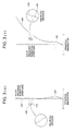
- Fig. 1 is a drawing showing the outline of the structure of the optical pickup device 100.
- the optical pickup device 100 of this embodiment is one capable of carrying out the reproducing and/or recording of information for two or more kinds of optical disks having different transparent substrate thicknesses respectively.
- these plural optical disks are explained in the order from high recording density to low one as the first optical disk (DVD) having the transparent substrate thickness t1, and the second optical disk (CD) having the transparent substrate thickness t2 which is different from t1, but the optical disk is not limited to these.
- the combining means 3 is a means capable of combining the light flux emitted from the first semiconductor laser 1 and the light flux emitted from the second semiconductor laser 2.
- a light flux is emitted from the first semiconductor laser, and the emitted light flux is transmitted through the combining means 3, the polarized beam splitter 4, the collimator lens 5, and the (1/4) ⁇ plate 6, to become a circularly polarized parallel light flux.
- This light flux is regulated by the aperture stop 7, and is converged on the recording surface 10a through the transparent substrate 10b of the first optical disk by the objective lens 8.
- the light flux which has been modulated by the information pits on the recording surface and reflected, is again transmitted through the objective lens 8, the (1/4) ⁇ plate 6, and the collimator lens 5, to enter the polarized beam splitter 4, by which it is reflected, and is given an astigmatism by the cylindrical lens 11, to enter the light detector 12 as a light receiving element (light receiving means); by using the signal outputted from the light detector 12, it is obtained the read signal of the information recorded in the first optical disk 10.
- the two-dimensional actuator 9 moves the objective lens 8 in such a way as to focus the beam from the first semiconductor laser 1 on the recording surface 10a of the first optical disk 10, as it moves the objective lens 8 in such a way as to focus the beam from the first semiconductor laser 1 on the predetermined track.
- a light flux is emitted from the second semiconductor laser 2; the emitted light flux has its optical path changed by the combining means 3, and is transmitted through the polarized beam splitter 4, the collimator lens 5, the (1/4) ⁇ plate 6, the aperture stop 7, and the objective lens 8, to be converged on the recording surface 10a' through the transparent substrate 10b of the second optical disk 10'.
- the light flux which has been modulated by the information pits on the recording surface 10a' and reflected, is again transmitted through the objective lens 8, the (1/4) ⁇ plate 6, the collimator lens 5, the polarized beam splitter 4, and the cylindrical lens 11, to enter the light detector 12, and by using the signal outputted from the light detector 12, it is obtained the read signal of the information recorded in the second optical disk 10'.
- the two-dimensional actuator 9 moves the objective lens 8 in such a way as to focus the beam from the second semiconductor laser 2 on the recording surface 10a' of the second optical disk 10', as it moves the objective lens 8 in such a way as to focus the beam from the second semiconductor laser 2 on the predetermined track.
- the objective lens 8 is moved by the two-dimensional actuator 9 in such manner as to make the beam spot form the smallest circle of confusion (the best focus).
- the size of the whole spot is larger than the smallest circle of confusion, but a nucleus having light quantity concentrated at the central portion and a flare, which is unnecessary light, around the nucleus are formed.
- the objective lens 8 is driven by the two-dimensional actuator 9 in such a manner as to be brought into the state of defocus (before focus).
- the optical pickup device of this embodiment is capable of converging the beams from the respective semiconductor lasers 1 and 2 on the recording surfaces 10a and 10a' of the respective optical disks 10 and 10' through the single objective lens 8.
- Fig. 2 comprises a cross-sectional view schematically showing the objective lens 8 for use in the optical pickup device 100 of this embodiment (a), and the front view as seen from the side of the light source (b).
- the single dot and dash line shows the optical axis.
- This objective lens 8 is a convex lens having a positive refracting power of which the refracting surface at the light source side S1 and the refracting surface at the optical disk side S2 are both aspherical-shaped. Further, the refracting surface at the light source side S1 of the objective lens is composed of the four divisional surfaces b1 to b4 which are concentric with respect to the optical axis. At each of the borders of the divisional surfaces, a step is provided, to form each of the divisional surfaces. Accompanied by it, the spherical aberration curve and the wave front aberration curve of the objective lens have a step produced at each of the positions corresponding to the above-mentioned border portions.
- the refracting surface S1 and the refracting surface S2 are designed to be such ones as to make the spherical aberration component of the wave front aberration 0.05 ⁇ 1 rms or under at the position of the best image plane.
- the refracting surface S1 designed in this way is applied to the first divisional surface b1 and the fourth divisional surface b4.
- the new refracting surface S1' is designed to be such one as to make the spherical aberration component of the wave front aberration 0.05 ⁇ 2 rms or under at the position of the best image plane for the transparent substrate thickness t3 (t1 ⁇ t3 ⁇ t2).
- This refracting surface S1' is applied to the second divisional surface b2 and the third divisional surface b3; however, because the optimization is done for the transparent substrate thickness t3, the best image plane is apparently formed at a position different from the position of the best image plane formed by the first divisional surface b1 and the fourth divisional surface b4, when the first optical disk is used.
- the wave front aberration has its gradient varied in the divisional surfaces, in such a way that it becomes decreasing toward right for a DVD and becomes a little increasing toward right for a CD.
- the fourth light flux LB4 is unnecessary for a CD, and on the recording surface of an optical disk, it irradiates the area at an interval from the main light spot as a flare. Because the quantity of this flare is small enough as compared to the main spot light, by merely making the aperture stop 7 equivalent to the required numerical aperture for a DVD, a CD can be reproduced without needing any means for varying the numerical aperture of the aperture stop 7.
- the optical pickup device 100 of this invention although four divisional surfaces b1 to b4 are provided, a plurality of focal points are not present in the respective disks, which is different from the case of an objective lens described in the conventional technology; therefore, it is possible to reduce the loss of spot light quantity.
- the wave front aberration of the rays in the required numerical aperture is made approximately an integral multiple of the wavelength, and because the light flux having passed the portion inside the required numerical aperture interferes one another to make the intensity higher, which makes the central intensity of the spot light higher; as a result of it, a sufficient reflected light quantity can be obtained from the optical disk, which enables a stable operation as the interchangeable optical pickup device 100.
- this invention is not to be limited to this embodiment.
- divisional surfaces are provided on the refracting surface S1 of the objective lens 8 in this embodiment, but they may be provided on another surface.
- the second divisional surface b2 and the third divisional surface b3 have the same aspherical shape in this embodiment, but it is of no problem to make them have different aspherical shapes respectively.
- these second and third divisional surfaces b2 and b3 are designed to have a small residual aberration for the transparent substrate thickness t3 (t1 ⁇ t3 ⁇ t2) in this embodiment for convenience' sake, it is possible not to use this method, but it is necessary only to make small the gradient of the wave front aberration for a DVD and for a CD as the result.
- steps are provided at the borders of the divisional surfaces in this embodiment; however, it is also appropriate that the border of one divisional surface and another divisional surface is not made stepwise, and is connected through a portion having a shape of a circular arc with a predetermined radius R.
- This circular arc-shaped portion may be one that is provided deliberately or it may be one that is provided unintentionally. As an example of this one provided unintentionally, it can be cited the circular arc-shaped portion at the border formed in working the mold in the case where an objective lens is formed by molding.
- divisional surfaces are provided to have a shape of concentric rings in this embodiment, but they are not limited to this shape, and it is appropriate to provide them in a shape of broken rings.
- the position of the best image plane formed by the first and fourth light flux in the case of using the first optical disk means the defocus position where the interference fringes of the first and fourth light flux become approximately straight, in an interference fringe measurement of the objective lens for the first optical disk supposed, with the area of the second and third light flux mask-processed.
- the interference fringes are not straight (apparently the position of the best image plane is different) because the optimization has been made for the transparent substrate thickness t3, but the areas where the wave front aberration becomes nearly an integral multiple of the wavelength increase. By such a design, the peak intensity of the spot light can be raised.
- the first light flux to (k-1)th light flux are used for the recording and/or reproducing of the first optical information recording medium and the second optical information recording medium, and the k-th light flux is used for the recording or reproducing of the first optical information recording medium; or it is desirable that the light flux passing the portion inside the required numerical aperture for the second optical information recording medium among the first light flux to the k-th light flux are used for the recording and/or reproducing of the first optical information recording medium and the second optical information recording medium, and it is desirable that the light flux passing the portion larger than the required numerical aperture for the second optical information recording medium are used for the recording and/or reproducing of the first optical information recording medium.
- the depth of the step of the ring-shaped divisional surface at the side toward the optical axis is different from the depth of its step at the side reverse to the optical axis.
- the shape of the aspherical surface is different from the shape of the aspherical surface of the other ring-shaped divisional surfaces.
- the light flux passing the larger portion than the required numerical aperture for the second optical information recording medium has a larger wave front aberration than 0.07 ⁇ 2 rms, more desirably 0.1 ⁇ 2 rms, or further more desirably 0.2 ⁇ 2 rms on the second optical information recording surface.
- the light flux passing the required numerical aperture for the second optical information recording medium have a smaller spherical aberration than 10 ⁇ m on the second information recording surface, and the light flux passing the required numerical aperture for the first optical information recording medium have a larger spherical aberration than 20 ⁇ m on the second information recording surface. It is more desirable that the light flux passing the required numerical aperture for the second optical information recording medium have a smaller spherical aberration than 5 ⁇ m on the second information recording surface, and the light flux passing the required numerical aperture for the first optical information recording medium have a larger spherical aberration than 50 ⁇ m on the second information recording surface.
- the ring-shaped divisional surface which at least two pieces of light flux among the second bundle to the (k-1)th bundle having the first wavelength pass, said two pieces of light flux forming the apparent best image plane at a position different from the position of the best image plane formed by the first and k-th light flux, has a strong refracting power.
- the difference of the wavelength between the light flux having the first wavelength from the first light source and the light flux having the second wavelength from the second light source is 80 nm or over.
- an apparatus for reproducing and/or recording optical information of this invention comprises an optical pickup device of this invention. Further, it is desirable that the apparatus comprises a spindle motor.
- This example of practice is an example of practice in the above-mentioned first embodiment.
- the lens data and the data of the aspherical surface are shown in Table 2 and in Table 3 respectively.
- the surface interval for the divisional surfaces (the thickness on the optical axis of the divisional surfaces described in the above table) is shown as the interval on the optical axis between the intersecting point of each of the divisional surfaces, which is extended to the optical axis in accordance with the expression of the aspherical surface shape, with the optical axis and the third surface.
- Each of the divisional surfaces is formed by the concentric circles about the optical axis, and its area is defined by the distance h from the optical axis.
- the expression of the aspherical surface is based on the following formula [M1]: where X denotes an axis in the direction of the optical axis, H denotes an axis perpendicular to the optical axis, the progressing direction of light is taken positive, K denotes the coefficient of cone, Aj denotes the coefficient of aspherical surface, and Pj denotes the number of power of the aspherical surface.
- the refracting surface S1 and the refracting surface S2 are designed to be such one as to make the residual aberration small (about 0.05 ⁇ 1 rms or under is suitable) in the case of using a DVD.
- the refracting surface S1 is composed of the four divisional surfaces b1 to b4, and this refracting surface S1 is applied to the first divisional surface b1 and the fourth divisional surface b4.
- This surface S1' is applied to the aspherical surface for the second divisional surface b2 and the third divisional surface b3.
- Fig. 3 shows the spherical aberration of the objective lens in this example of practice
- Fig. 4 and Fig. 5 show the wave front aberrations of the objective lens in this example of practice respectively.
- the second divisional surface b2 and the third divisional surface b3 have the thickness on the optical axis shifted from each other by 0.1 ⁇ m, and the amount of stepwise difference in the aberration curve at the pertinent positions is more remarkable for the wave front aberration as compared to the spherical aberration; the aim of the design is to broaden the area where the wave front aberration is approximately an integral multiple of the wavelength used.
- the thickness on the optical axis of the third divisional surface is the same as that of the second divisional surface, it increases the area where the wave front aberration of the third divisional surface b3 deviates from -4 ⁇ 1 rms, and as a result of it, the central intensity of the spot light for a DVD is reduced by 4.1% as compared to this example of practice.
- the approximate integers m i and n i for the wave front aberration of the respective divisional surfaces are such as shown in Table 4.
- Fig. 7 shows the spot light profiles of the objective lens in this example of practice on the recording surface of the respective optical disks, and it can be confirmed that the objective lens is compatible to the spot sizes required for the respective media.
- An optical pickup device of this embodiment is similar to the above-mentioned one aside from the point that there are six divisional surfaces formed on the refracting surface S1 of the objective lens 18; therefore, explanation of the overlapping portions will be omitted, and only the objective lens 18 will be explained in detail.
- the optical pickup device of this embodiment can carry out recording and/or reproducing of information for two or more kinds of optical disks.
- these plural optical disks will be explained in the order from high recording density to low one, as the first optical disk (a DVD-RAM) having the transparent substrate thickness t1 and the second optical disk (a CD-RW) having the transparent substrate thickness t2 which is different from t1.
- Fig. 8 are the cross-sectional view schematically showing the objective lens 18 for use in an optical pickup device of this embodiment (a), and its front view as seen from the side of the light source (b).
- the single dot and dash line shows the optical axis.
- This objective lens 18 is a convex lens having a positive refracting power of which the refracting surface at the light source side S1 and the refracting surface at the optical disk side S2 are both aspherical-shaped. Further, the refracting surface at the light source side S1 of the objective lens 18 is composed of the six divisional surfaces b1 to b6 which are concentric with respect to the optical axis. At each of the borders of the divisional surfaces, a step is provided, to form each of the divisional surfaces. Accompanied by it, the spherical aberration curve and the wave front aberration curve of the objective lens have a step produced at each of the positions corresponding to the above-mentioned border portions.
- the refracting surface S1 and the refracting surface S2 are designed to be such ones as to make the spherical aberration component of the wave front aberration 0.05 ⁇ 1 rms or under at the position of the best image plane.
- the refracting surface S1 designed in this way is applied to the first divisional surface b1, the fourth divisional surface b4, and sixth divisional surface b6.
- the new refracting surface S1" is designed to be such one as to make the spherical aberration component of the wave front aberration 0.05 ⁇ 2 rms or under at the position of the best image plane for the transparent substrate thickness t3 (t1 ⁇ t3 ⁇ t2).
- This refracting surface S1" is applied to the second divisional surface b2, the third divisional surface b3, and the fifth divisional surface b5; however, because the optimization is done for the transparent substrate thickness t3, the best image plane is apparently formed at a position different from the position of the best image plane formed by the first divisional surface b1, the fourth divisional surface b4, and the sixth divisional surface b6, when the first optical disk is used.
- the wave front aberration has its gradient varied in the divisional surfaces, in such a way that it becomes decreasing toward right for a DVD-RAM and becomes a little increasing toward right for a CD in the reverse way.
- t3 it is not desirable to make t3 ⁇ t1, because the gradient of the wave front aberration becomes too large for a CD-RW. It is also not desirable to make t3 ⁇ t2 in the reverse way, because the gradient of the wave front aberration becomes too large for a DVD-RAM. If t3 is desirably made to satisfy the condition (0.8 mm ⁇ t3 ⁇ 1.0 mm), the gradient of the wave front aberration can be made small for a DVD-RAM and for a CD-RW.
- the correction of wave front aberration can be done at each of the position of the smallest circle of confusion of the beam spot for a DVD-RAM and the before-focus position for a CD-RW. That is, for a DVD-RAM, the rays in the first to sixth light flux LB1 to LB6 are converged at the position of the smallest circle of confusion by the objective lens, and have a wave front aberration approximately of an integral multiple of the wavelength ⁇ 1 at the above-mentioned position of the smallest circle of confusion.
- the rays in the first to fifth light flux LB1 to LB5 have a wave front aberration approximately of an integral multiple of the wavelength ⁇ 2 at the above-mentioned before-focus position.
- the wave front aberration of the rays inside the required numerical aperture is made approximately an integral multiple of the wavelength, which raises the energy of the nucleus of the beam spot, and as the result of it, a sufficient quantity of the reflected light can be obtained from the optical disk, which enables a stable operation for the optical pickup device.
- this invention is not to be limited to this embodiment.
- divisional surfaces are provided on the refracting surface S1 of the objective lens 18; however, this invention is not limited to this, and it is possible to provide them on an optical element in the other converging optical system, or it is also possible to provide a separate optical element.
- the second divisional surface, the third divisional surface, and the fifth divisional surface have the same aspherical shape in this embodiment, but it is of no problem to make them have different aspherical shapes respectively.
- a step is provided at each of the borders of the divisional surfaces in this embodiment; however it is also possible that the border of one divisional surface and another divisional surface is not made stepwise and is connected through a portion having a shape of a circular arc with a predetermined radius R.
- This circular arc-shaped portion may be one that is provided deliberately or it may be one that is provided unintentionally. As an example of this one provided unintentionally, it can be cited the circular arc-shaped portion at the border formed in working the mold in the case where an objective lens is formed by molding.
- the divisional surfaces are provided to have a shape of concentric rings in this embodiment, but they are not limited to this shape, and it is appropriate to provide them in a shape of broken rings.
- This example of practice is an example of practice in the above-mentioned second embodiment.
- the lens data and the data of the aspherical surface are shown in Table 5 and in Table 6 respectively.
- i-th surface is shown in the consecutive order in accordance with the light progressing direction up to the information recording surface of the optical disks 10 and 10'.
- the cover glass of the semiconductor lasers 1 and 2, the polarized beam splitter 4, the collimator lens 5, and the (1/4) ⁇ plate 6 are omitted.
- r denotes the radius of curvature of the surfaces
- d denotes the space between the i-th surface and the (i+1)th surface
- n denotes the refractive index.
- the first surface is the aperture stop 7, and when a DVD-RAM or a CD-RW is used, the diameter of the aperture ⁇ is equal to 3.97 mm for either.
- the surface interval for the divisional surfaces (the thickness on the optical axis of the divisional surfaces described in the above table) is shown as the interval on the optical axis between the intersecting point of each of the divisional surfaces, which is extended to the optical axis in accordance with the expression of the aspherical surface shape, with the optical axis and the third surface.
- Each of the divisional surfaces is formed by the concentric circles about the optical axis, and its area is defined by the distance h from the optical axis.
- the expression of the aspherical surface is based on the above-mentioned formula [M1], where X denotes an axis in the direction of the optical axis, H denotes an axis perpendicular to the optical axis, the progressing direction of light is taken positive, ⁇ denotes the coefficient of cone, Aj denotes the coefficient of aspherical surface, and Pj denotes the number of power of the aspherical surface.
- the refracting surface S1 and the refracting surface S2 are designed to be such one as to make the residual aberration small in the case of using a DVD-RAM.
- the refracting surface S1 is composed of the six divisional surfaces b1 to b6, and this refracting surface S1 is applied to the first divisional surface b1, the fourth divisional surface b4, and the sixth divisional surface b6.
- This surface S1' is applied to the aspherical surface for the second divisional surface b2, the third divisional surface b3, and the fifth divisional surface b5.
- Fig. 9 shows the spherical aberration of the objective lens 18 in this example of practice
- Fig. 10 and Fig. 11 show the wave front aberrations of the objective lens 18 in this example of practice respectively.
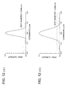
- NA2 0.50
- the wave front aberration is shown with the part in which the numerical aperture is 0.60 or larger omitted.
- Fig. 12 shows the spot light profiles of the objective lens 18 in this example of practice on the recording surface of the respective optical disks, and it can be confirmed that the objective lens is compatible to the spot sizes required for the respective media.
- the divisional surfaces are provided on the objective lens, but it is also possible to provide them on a lens in other converging optical system (for example, a coupling lens for converting the angle of divergence of the light flux such as a collimator lens which makes a divergent light flux from a light source approximately a parallel light flux). In other way, it is also possible to provide them on another optical element such as a diffraction element or a prism, or to arrange in the optical path an optical element provided with them.
- an optical pickup device and an objective lens capable of correcting the deviation of wave front aberration in the divisional surfaces inside the required numerical apertures for a plurality of optical disks. Further, it is possible to provide an optical pickup device and an objective lens having a small amount of loss of light quantity and an excellent S-letter characteristic.
Applications Claiming Priority (3)
| Application Number | Priority Date | Filing Date | Title |
|---|---|---|---|
| JP35193099 | 1999-12-10 | ||
| JP35193099 | 1999-12-10 | ||
| PCT/JP2000/008672 WO2001043127A1 (fr) | 1999-12-10 | 2000-12-07 | Objectif et capteur optique |
Publications (2)
| Publication Number | Publication Date |
|---|---|
| EP1168317A1 true EP1168317A1 (fr) | 2002-01-02 |
| EP1168317A4 EP1168317A4 (fr) | 2006-06-21 |
Family
ID=18420601
Family Applications (1)
| Application Number | Title | Priority Date | Filing Date |
|---|---|---|---|
| EP00979983A Withdrawn EP1168317A4 (fr) | 1999-12-10 | 2000-12-07 | Objectif et capteur optique |
Country Status (5)
| Country | Link |
|---|---|
| US (1) | US6781943B2 (fr) |
| EP (1) | EP1168317A4 (fr) |
| KR (1) | KR20010102007A (fr) |
| CN (1) | CN1189878C (fr) |
| WO (1) | WO2001043127A1 (fr) |
Cited By (2)
| Publication number | Priority date | Publication date | Assignee | Title |
|---|---|---|---|---|
| EP3370099A4 (fr) * | 2016-01-12 | 2018-12-05 | Samsung Electronics Co., Ltd. | Combinaison de lentilles et dispositif d'affichage comprenant celle-ci |
| WO2023204621A1 (fr) * | 2022-04-21 | 2023-10-26 | 한양대학교 산학협력단 | Lentille intraoculaire multifocale diffractive composite |
Families Citing this family (8)
| Publication number | Priority date | Publication date | Assignee | Title |
|---|---|---|---|---|
| JP3864749B2 (ja) * | 2001-10-11 | 2007-01-10 | コニカミノルタホールディングス株式会社 | 光ピックアップ装置の光学系及び光ピックアップ装置の対物レンズ |
| JP4175092B2 (ja) * | 2002-11-06 | 2008-11-05 | 日本電気株式会社 | 光ヘッド装置および光学式情報記録再生装置 |
| CN1305053C (zh) * | 2003-04-28 | 2007-03-14 | 株式会社三协精机制作所 | 光学头装置及光学头装置用物镜 |
| JP2004326984A (ja) * | 2003-04-28 | 2004-11-18 | Sankyo Seiki Mfg Co Ltd | 光ヘッド装置、および光ヘッド装置用対物レンズ |
| JP4170231B2 (ja) * | 2004-01-13 | 2008-10-22 | Hoya株式会社 | 光ディスク用対物レンズ |
| CN100449622C (zh) * | 2004-02-27 | 2009-01-07 | 柯尼卡美能达精密光学株式会社 | 物镜光学系统、光拾取装置以及光信息记录再生装置 |
| JP2005293765A (ja) * | 2004-04-02 | 2005-10-20 | Konica Minolta Opto Inc | 光ピックアップ装置 |
| US7821906B2 (en) * | 2004-06-21 | 2010-10-26 | Hoya Corporation | Objective lens for optical pick-up |
Family Cites Families (13)
| Publication number | Priority date | Publication date | Assignee | Title |
|---|---|---|---|---|
| US4768867A (en) * | 1985-09-02 | 1988-09-06 | Canon Kabushiki Kaisha | Aspherical single lens |
| KR910002322B1 (ko) * | 1986-09-20 | 1991-04-11 | 후지쓰 가부시끼가이샤 | 회절격자렌즈 조립체를 구비하고 있는 광학시스템 |
| US5754512A (en) * | 1995-05-30 | 1998-05-19 | Matsushita Electric Industrial Co., Ltd. | Correction elements to lower light intensity around an optical axis of an optical head with a plurality of focal points |
| US5838653A (en) * | 1995-10-04 | 1998-11-17 | Reveo, Inc. | Multiple layer optical recording media and method and system for recording and reproducing information using the same |
| JP3837805B2 (ja) * | 1995-12-19 | 2006-10-25 | コニカミノルタホールディングス株式会社 | 光ピックアップ装置、集光光学系、対物レンズ、再生方法及び光ディスク装置 |
| DE69720641T2 (de) * | 1996-10-23 | 2004-04-08 | Konica Corp. | Verfahren zur Aufzeichnung und Wiedergabe eines optischen Aufzeichnungsträgers, Objektivlinse sowie Herstellungsmethode der Objektivlinse |
| JP3484038B2 (ja) * | 1997-03-13 | 2004-01-06 | 株式会社日立製作所 | 対物レンズおよびそれを用いた光ヘッド |
| JPH10269611A (ja) * | 1997-03-27 | 1998-10-09 | Pioneer Electron Corp | 光ピックアップ及びそれを用いた多層ディスク再生装置 |
| JPH112759A (ja) * | 1997-06-13 | 1999-01-06 | Pioneer Electron Corp | 対物レンズ |
| JP3827860B2 (ja) * | 1998-03-31 | 2006-09-27 | パイオニア株式会社 | 対物レンズ及び光ピックアップ装置 |
| TW432225B (en) * | 1998-06-03 | 2001-05-01 | Konishiroku Photo Ind | Optical pickup apparatus |
| TW479253B (en) * | 1998-12-17 | 2002-03-11 | Konishiroku Photo Ind | Objective lens for correcting chromatic aberration for use in recording toor reproducing from optical information recording medium and optical pickup apparatus therewith |
| JP2000231057A (ja) * | 1999-02-10 | 2000-08-22 | Konica Corp | 対物レンズ及び光ピックアップ装置 |
-
2000
- 2000-12-07 CN CNB008017506A patent/CN1189878C/zh not_active Expired - Fee Related
- 2000-12-07 KR KR1020017010057A patent/KR20010102007A/ko not_active Application Discontinuation
- 2000-12-07 US US09/786,438 patent/US6781943B2/en not_active Expired - Fee Related
- 2000-12-07 WO PCT/JP2000/008672 patent/WO2001043127A1/fr not_active Application Discontinuation
- 2000-12-07 EP EP00979983A patent/EP1168317A4/fr not_active Withdrawn
Non-Patent Citations (2)
| Title |
|---|
| No further relevant documents disclosed * |
| See also references of WO0143127A1 * |
Cited By (3)
| Publication number | Priority date | Publication date | Assignee | Title |
|---|---|---|---|---|
| EP3370099A4 (fr) * | 2016-01-12 | 2018-12-05 | Samsung Electronics Co., Ltd. | Combinaison de lentilles et dispositif d'affichage comprenant celle-ci |
| US10890695B2 (en) | 2016-01-12 | 2021-01-12 | Samsung Electronics Co., Ltd. | Compound lens and display device having the same |
| WO2023204621A1 (fr) * | 2022-04-21 | 2023-10-26 | 한양대학교 산학협력단 | Lentille intraoculaire multifocale diffractive composite |
Also Published As
| Publication number | Publication date |
|---|---|
| CN1335986A (zh) | 2002-02-13 |
| CN1189878C (zh) | 2005-02-16 |
| US20020191526A1 (en) | 2002-12-19 |
| US6781943B2 (en) | 2004-08-24 |
| KR20010102007A (ko) | 2001-11-15 |
| EP1168317A4 (fr) | 2006-06-21 |
| WO2001043127A1 (fr) | 2001-06-14 |
Similar Documents
| Publication | Publication Date | Title |
|---|---|---|
| EP0838812B1 (fr) | Procédé d'enregistrement et de reproduction d'un disque optique, lentille d'objectif et méthode de réalisation de cette lentille | |
| US6313956B1 (en) | Optical pickup apparatus and objective lens | |
| US6370103B1 (en) | Objective lens for correcting chromatic aberration for use in recording to or reproducing from optical information recording medium and optical pickup apparatus therewith | |
| EP2264708A2 (fr) | Lentille d'objectif, système optique convergent lumineux, appareil de capture optique et appareil d'enregistrement/reproduction | |
| JP4660915B2 (ja) | 光ピックアップ装置 | |
| US6363037B1 (en) | Optical pickup apparatus with objective lens having a phase shift section | |
| JPH1196585A (ja) | 光情報記録媒体の記録/再生方法、光ピックアップ装置、集光光学系、対物レンズ及び対物レンズの設計方法 | |
| EP1168317A1 (fr) | Objectif et capteur optique | |
| EP1174866B1 (fr) | Lentille d'objectif pour différents supports d'enregistrement optique et appareil de lecture optique l'utilisant | |
| US8194522B2 (en) | Aspheric lens and optical pickup including the same | |
| US6052355A (en) | Optical pickup apparatus and a compensation element therefor | |
| CN101124632A (zh) | 光拾取装置 | |
| US20050117496A1 (en) | Objective optical system and optical pickup device using it | |
| JP2000056216A (ja) | 光ピックアップ用光学系および光ピックアップ装置 | |
| JPH10143905A (ja) | 光ピックアップ装置、対物レンズおよび対物レンズの設計方法 | |
| JP2000028917A (ja) | 光情報記録媒体の記録再生用光ピックアップ装置、対物レンズ及び対物レンズの設計方法 | |
| JP2001229567A (ja) | 対物レンズ及び光ピックアップ装置 | |
| US20040184386A1 (en) | Optical pickup apparatus | |
| JP4366813B2 (ja) | 光ピックアップ装置及び光ピックアップ装置用のカップリングレンズ | |
| KR100492834B1 (ko) | 광정보기록매체의기록/재생방법,광픽업장치,대물렌즈및대물렌즈의설계방법 | |
| JP2000028918A (ja) | 光ピックアップ装置用集光光学系 | |
| JP4394136B2 (ja) | 位相補償板つきピックアップレンズ及びそれを用いた光ピックアップ装置 | |
| JP4394137B2 (ja) | 位相補償板つきピックアップレンズ及びそれを用いた光ピックアップ装置 | |
| JP2001174697A (ja) | 対物レンズ及び光ピックアップ装置 | |
| JP3567406B2 (ja) | 記録再生用対物単レンズ |
Legal Events
| Date | Code | Title | Description |
|---|---|---|---|
| PUAI | Public reference made under article 153(3) epc to a published international application that has entered the european phase |
Free format text: ORIGINAL CODE: 0009012 |
|
| 17P | Request for examination filed |
Effective date: 20010319 |
|
| AK | Designated contracting states |
Kind code of ref document: A1 Designated state(s): AT BE CH CY DE DK ES FI FR GB GR IE IT LI LU MC NL PT SE TR |
|
| AX | Request for extension of the european patent |
Free format text: AL PAYMENT 20010319;LT PAYMENT 20010319;LV PAYMENT 20010319;MK PAYMENT 20010319;RO PAYMENT 20010319;SI PAYMENT 20010319 |
|
| RAP1 | Party data changed (applicant data changed or rights of an application transferred) |
Owner name: KONICA MINOLTA OPTO, INC. |
|
| A4 | Supplementary search report drawn up and despatched |
Effective date: 20060518 |
|
| STAA | Information on the status of an ep patent application or granted ep patent |
Free format text: STATUS: THE APPLICATION HAS BEEN WITHDRAWN |
|
| 18W | Application withdrawn |
Effective date: 20060817 |