EP1168058A1 - Schärfenkontrolle in einer fotografischen Reproduktionsvorrichtung - Google Patents
Schärfenkontrolle in einer fotografischen Reproduktionsvorrichtung Download PDFInfo
- Publication number
- EP1168058A1 EP1168058A1 EP00113039A EP00113039A EP1168058A1 EP 1168058 A1 EP1168058 A1 EP 1168058A1 EP 00113039 A EP00113039 A EP 00113039A EP 00113039 A EP00113039 A EP 00113039A EP 1168058 A1 EP1168058 A1 EP 1168058A1
- Authority
- EP
- European Patent Office
- Prior art keywords
- photographic
- pattern
- film
- image
- reference position
- Prior art date
- Legal status (The legal status is an assumption and is not a legal conclusion. Google has not performed a legal analysis and makes no representation as to the accuracy of the status listed.)
- Granted
Links
Images


Classifications
-
- H—ELECTRICITY
- H04—ELECTRIC COMMUNICATION TECHNIQUE
- H04N—PICTORIAL COMMUNICATION, e.g. TELEVISION
- H04N1/00—Scanning, transmission or reproduction of documents or the like, e.g. facsimile transmission; Details thereof
- H04N1/00127—Connection or combination of a still picture apparatus with another apparatus, e.g. for storage, processing or transmission of still picture signals or of information associated with a still picture
- H04N1/00249—Connection or combination of a still picture apparatus with another apparatus, e.g. for storage, processing or transmission of still picture signals or of information associated with a still picture with a photographic apparatus, e.g. a photographic printer or a projector
- H04N1/00267—Connection or combination of a still picture apparatus with another apparatus, e.g. for storage, processing or transmission of still picture signals or of information associated with a still picture with a photographic apparatus, e.g. a photographic printer or a projector with a viewing or projecting apparatus, e.g. for reading image information from a film
-
- G—PHYSICS
- G02—OPTICS
- G02B—OPTICAL ELEMENTS, SYSTEMS OR APPARATUS
- G02B7/00—Mountings, adjusting means, or light-tight connections, for optical elements
- G02B7/28—Systems for automatic generation of focusing signals
-
- H—ELECTRICITY
- H04—ELECTRIC COMMUNICATION TECHNIQUE
- H04N—PICTORIAL COMMUNICATION, e.g. TELEVISION
- H04N1/00—Scanning, transmission or reproduction of documents or the like, e.g. facsimile transmission; Details thereof
- H04N1/00127—Connection or combination of a still picture apparatus with another apparatus, e.g. for storage, processing or transmission of still picture signals or of information associated with a still picture
- H04N1/00249—Connection or combination of a still picture apparatus with another apparatus, e.g. for storage, processing or transmission of still picture signals or of information associated with a still picture with a photographic apparatus, e.g. a photographic printer or a projector
-
- H—ELECTRICITY
- H04—ELECTRIC COMMUNICATION TECHNIQUE
- H04N—PICTORIAL COMMUNICATION, e.g. TELEVISION
- H04N1/00—Scanning, transmission or reproduction of documents or the like, e.g. facsimile transmission; Details thereof
- H04N1/024—Details of scanning heads ; Means for illuminating the original
- H04N1/02409—Focusing, i.e. adjusting the focus of the scanning head
-
- H—ELECTRICITY
- H04—ELECTRIC COMMUNICATION TECHNIQUE
- H04N—PICTORIAL COMMUNICATION, e.g. TELEVISION
- H04N1/00—Scanning, transmission or reproduction of documents or the like, e.g. facsimile transmission; Details thereof
- H04N1/04—Scanning arrangements, i.e. arrangements for the displacement of active reading or reproducing elements relative to the original or reproducing medium, or vice versa
- H04N1/19—Scanning arrangements, i.e. arrangements for the displacement of active reading or reproducing elements relative to the original or reproducing medium, or vice versa using multi-element arrays
- H04N1/195—Scanning arrangements, i.e. arrangements for the displacement of active reading or reproducing elements relative to the original or reproducing medium, or vice versa using multi-element arrays the array comprising a two-dimensional array or a combination of two-dimensional arrays
Definitions
- the present invention relates to a photographic detection device according to the preamble of claim 1, in particular a scanner for scanning Film or use a photographic printer to expose it in a photographic Film contained, individual picture templates ("frames") on photo paper.
- the present invention relates in particular to checking or adjusting the Sharpness of the image of a photographic medium (e.g. film, transparent film with image, photo paper with image) on a detection means (e.g. photoelectric Transducers such as CCD, e.g. photochemical converter, e.g. Photo paper) in of such a photographic detection device.
- a photographic medium e.g. film, transparent film with image, photo paper with image
- a detection means e.g. photoelectric Transducers such as CCD, e.g. photochemical converter, e.g. Photo paper
- test film or a test negative that in the place of a film on a film stage at a given Reference position is attached.
- the operator must manually Test film can be introduced into the film conveyor or a test negative by hand attached and positioned on the film stage. The sharpness of the with The test film or test negative generated test image is then used by an operator judged and the position of the lens is changed until a satisfied significant result is achieved.
- the object of the invention is to provide a photographic detection device, in which the focus check or focus adjustment is simplified and is reproducible.
- the detection device according to the invention can be used as a photographic scanner (Scanner) are formed by using a photoelectric as a detection means Converter (CCD) is used. It can also be used as a photographic copier (Printer) are formed by using a photochemical as a detection means Converter (photo paper) is used.
- Scanner photographic scanner
- Print photographic copier
- photo paper photo paper
- the photographic capture device has a light source, e.g. a halogen lamp or LEDs.
- the light from the light source is preferably bundled and via light-guiding means (lenses, lenses, mirrors, diaphragms etc.) for a stage led to the positioning of a photographic Medium serves.
- the spectrum of light can be changed, e.g. about filters or by controlling different colored LEDs.
- the light transmitted by the photographic medium is measured by the photographic Medium is imaged on a detector. But it can also reflect Light can be captured using imaging optics.
- the detection means is suitable for detecting the light modulated by transmission or reflection, so as to add the image information stored on the photographic medium to capture.
- CCD and photo paper are suitable detection means.
- the photographic detection device advantageously has a device for check the sharpness of the image and in particular to make an adjustment to allow the sharpness of the image.
- This device records according to the invention a so-called sample carrier with a pattern and a positioning mechanism around which Bring the sample carrier into a desired reference position.
- the mechanics are like this trained that the sample carrier for each measurement to check the Sharpness is positioned at the same reference position.
- the sample carrier is always in the same object level (level in which the object to be imaged is placed). This represents an essential one Advantage over the use of test negatives or test films. Conventional Test films or test negatives can face the lamp or arch towards the detection means and thus leave a predetermined object plane.
- the curvature can change with the ambient temperature, orientation of the test negative or change the type of test film or test negative in the direction and extent.
- the sample carrier with pattern according to the invention is preferably so rigid trained that the pattern does not bulge.
- the sample carrier formed as a rigid metal grid, the shape of the grid representing the pattern.
- the sample carrier preferably has a non-flexible or non-elastic one or rigid substrate that carries, forms or encloses the pattern and prevents the pattern from buckling.
- the pattern that the review of Sharpness of the image is used, is so rich in contrast that it at least a sharp image can be recognized by the detection means. It can e.g. a grid, circles or other geometric figures.
- the substrate that bears the pattern is preferably transparent while the pattern itself is not transparent, or vice versa, so as much as possible to achieve strong light / dark contrast in the imaging plane.
- the sample carrier is preferably positioned at the same reference position as in the conventional Operation of the detection device the photographic medium for detection is positioned. The reference position is chosen so that the pattern located in the specified object level.
- the mechanics used to position the sample carrier optionally allow bring the sample carrier to the reference position or remove it from there.
- the sample carrier is removed so far that it represents an image photographic medium on the detection medium is not affected.
- the mechanics preferably comprise positioning means, e.g. Rails, Swivel arms, rotors.
- Retaining means such as e.g. grid or jacks provided.
- servomotors especially in connection with a gear (tooth rims).
- the mechanics particularly preferably serve a dual purpose, namely Positioning the sample carrier and positioning a pressure mask for Printing a photographic medium (film) on a stage (film stage) the specified reference position.
- the films to be captured are conventionally located with their edges, which have no picture, on film guides. against these edges are pressed on the films using a pressure mask, so that the Film picture (frame) is as possible in a defined level that the object level in representing the imaging geometry. Because the mask is not needed or not absolutely necessary is when the sharpness of the image is checked using the sample carrier is, the mechanics is preferably designed so that an exchange between a mask and the sample carrier.
- the Sample carriers are placed on a sled together with one or more masks, where necessary, a mask or the sample carrier to the reference position is feasible.
- the exchange or positioning of the sample carrier and the mask can preferably also be carried out automatically controllable by a control device.
- At least one mask is preferably on one together with the sample carrier Supporting member, e.g. a sled, arranged so that the at least one Mask and the pattern carrier have a fixed positional relationship to each other.
- the Support member is preferably along a predetermined path, e.g. by means of Rails, or a rotor mounted on an axis.
- the path runs preferably transversely to the transport direction of the film.
- the positioning along of the path can be monitored using sensors.
- the detection result can also be used as a detection means, ie the position of the detection pattern detected with the photoelectric converter, for positioning with the help of control electronics.
- the pattern carriers are preferably arranged between two masks, so to achieve the most compact possible arrangement and the smallest possible To have adjustment path between sample carrier and mask.
- the sample carriers can e.g. in mechanically caused gaps between the masks e.g. between holding means (screws) or mask frames, and in particular have significantly smaller dimensions than the masks (e.g. smaller than a quarter the size of a mask) to make the arrangement particularly compact shape.
- the pattern carrier has a substrate and the pattern that of the Substrate is carried on.
- the substrate is preferably rigid and preferably has a flat surface on which the pattern is located.
- the substrate is particularly designed so that it is due to the heat of Light source not deformed.
- a transparent material is used as the substrate, such as. Glass or transparent plastic, e.g. Plexiglass, used.
- the pattern can be created in different ways. For example can reflective or light absorbing material according to a predetermined Patterns are evaporated onto the substrate. To create the pattern can e.g. cover the substrate except for the pattern. Also a photoresist can be applied, exposed according to the pattern and then be fixed. Also e.g. Pattern carved into the substrate become. The resulting recesses can e.g. with a light absorbing and / or light-reflecting material.
- the thickness of the material forming the pattern is preferably of the order of magnitude the thickness of a photographic layer of a film, the photographic Layer that represents and carries image information. That way creates conditions for the sample carrier, as is the case with a film are.
- the thickness of the pattern is e.g. 10 ⁇ m to 100 ⁇ m.
- the surface of the substrate does not necessarily have to be flat, it can according to the imaging geometry to be slightly curved to avoid aberrations compensate and enable optimal focusing.
- the substrate is flat.
- the photographic layer of a film is usually arranged to match the Detector indicates.
- the sample carrier is preferably arranged so that the substrate points to the light source and the actual pattern to the Detector.
- a major advantage of the invention is that the sample carrier is always is positioned the same, so that the pattern is always repeatable in the same Level. This was when using test films or test images not the case due to the curvature given there. Depending on the used The test image could thus deceptively change the focus setting from the apparent one offer optimally. This problem is due to the same repeatable situation of the pattern eliminated using the positioning mechanism.
- the photographic detection device comprises a device for automatic checking of sharpness and / or automatic focusing.
- the detection means preferably comprises a photoelectric one Converter device on which the carrier pattern is imaged.
- a readout electronics and a data processing device e.g. computer, CPU
- the readout electronics reads those generated by the light electrical signals from the converter device and leads them to the data processing device to.
- the signals that represent the image are represented by the Data processing device with regard to the sharpness of the pattern shown evaluated.
- the contrast difference i.e. the light / dark difference, between neighboring pixels.
- the pattern is preferably designed so that the areas are as possible cover a few pixels. For example, the number of pixels covered, that have a gray value or image value above a certain threshold, be known. If the image is blurred, this number increases. Can too Sample evaluation methods are used, especially for the edge area of a pattern are sensitive. In this way, a parameter can be assigned to each image can be calculated, which quantifies the sharpness of the image. Such Focus determination can also be performed locally, at different points in the pattern e.g. in the four corners of the picture. If necessary, the focus assessment also done separately in different colors.
- a photochemical converter device Used as a means of detection uses a photochemical converter device, this can be done by the Transducer device captured measurement image (automatically) with a scanner and then by the data processing device with regard to the sharpness of the Patterns are evaluated.
- the automatic focus check or Focus can thus be analogous to the embodiment with an electrical converter device respectively.
- the data processing device detects a blur, e.g. a warning signal is issued which prompts an operator to renew Focused.
- Checking the focus can be done regularly to ensure a permanently sharp image in the detection device to ensure.
- the mechanics e.g. combined with a timer, around, if there is no film, the sample carrier by means of the mechanics for checking the sharpness of the reference position at regular intervals position.
- control electronics are preferably provided and an adjustment mechanism that allows at least one of the following devices able to adjust along the optical imaging path: the Film stage with reference position or object level, the imaging optics and that Detection means.
- the imaging optics (in particular a lens) are preferred or a lens or a lens system) by means of an adjustment mechanism in the The position changes while the position of the stage and the detection means remains fixed.
- the adjustment mechanism can e.g. can be combined with an electric motor that is controlled by the control electronics.
- the regulation can e.g. after this conventional set / actual principle or according to a fuzzy logic principle. Adjustment is preferably carried out until the sharpness within one specified tolerance range, e.g. is defined by a threshold, lies.
- the sharpness is divided into several (e.g. 10 to 20) positions measured and then the position of optimal sharpness from the different measuring points determined.
- the adjustment mechanism then moves in this determined position of optimal sharpness.
- the sharpness is also in everyone Position measured in different colors, so there is the possibility of the optimal To determine the position even more precisely or particularly well for a color optimize.
- Preferably comprises a support member on which there is at least one pressure mask and the sample carrier is also assigned to the pressure masks Film guides.
- the film guides lead film in one direction is preferably transverse to the direction of adjustment of the support member.
- the mechanism for positioning the Sample carrier also have a rotor.
- This is preferably adjustable in rotation stored around an axis. This axis preferably runs at least essentially parallel to the direction of transport of the film or photographic medium.
- the rotor preferably has the sample carrier on its circumference. additionally can use masks (pressure masks) for different film formats on the Scope should be provided. A single pressure mask or the sample carrier can selectively by rotating the rotor to the reference position for the image be performed.
- the inventive one photographic capture device for example as a scanning device (scanner) educated.
- a scanning device scanner
- a transport device for the photo paper can be realized.
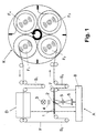
- FIG. 1 shows the scanning device according to the invention for better understanding in the context of known upstream and downstream components.
- These components are a rotatable film carousel K with four film reels F 1 -F 4 thereon and an image position (frame) detector D.
- the film carousel K, the image position detector D and the scanning device designated as a whole by A are arranged by three loop arrangements S. 1 -S 3 mechanically decoupled from each other.
- the film carousel K and the mechanical decoupling by means of the loop arrangements S 1 -S 3 are in the already mentioned US patent application Ser. No. 09 / 384,221 (corresponding to European Patent Application No. 98 116 162.3) described in detail and therefore need no further explanation.
- a film F to be scanned and possibly notched is drawn off from the film reel F 1 , passes through the image position detector D and the scanning device A in succession and is finally wound onto the film reel F 2 .
- the image point detector D determines the relative positions of the individual image templates (frames) on the film.
- the scanning device A evaluates this position information for the positioning of the individual image templates in it. In detail, this can be done, for example, as in US Pat. No. 5,285,235, so that the person skilled in the art does not need any further explanation.
- the scanning device A itself comprises a film stage 1 for the person to be scanned Film F, a film notching device arranged according to the invention in or on the film stage 1 2, e.g. White light source 3, a halogen lamp for example, color sequential color shutter 4, an imaging optics 5 and one e.g. designed as a two-dimensional array of CCD photodiodes Photoelectric converter 6. Furthermore, means symbolized by rollers 7 for Transport of the film F through the scanning device and electronics 8 for Control of all electrical and electronic components of the scanning device, in particular also the transport and positioning of the film F or the image templates provided on it.
- the light coming from the light source 3 passes through the color closure 4 and then acts on those positioned in the film stage 1 to be scanned, on the Film F included image templates V (Fig.3).
- the image templates V are by means of Imaging optics 5 imaged on the photoelectric converter 6. This solves everyone Image template V to be scanned locally into individual pixels and converts the intensity of the measuring light emanating from each individual pixel of an original into a corresponding electrical scanning signal.
- the image template V and thus the photoelectric converter 6 is also controlled by the color lock 4 sequentially for a certain exposure time with measuring light three or more different colors, and that with each exposure resulting scanning signals are sent by the electronics after each exposure 8 read out.
- a carriage 11 is arranged on the film stage 1, which in the film stage 1 in a guide 11a transverse to the transport path P of Film F is arranged adjustable.
- the carriage 11 has two to the transport path P parallel trough-shaped film guides 12 and 13 for different widths Film formats are designed.
- the film guide 12 is on the 135 format and the film guide 13 matched to the 24 mm format.
- the carriage 11 and the guide 11a represent components of the positioning mechanism for the sample carrier.
- scanning window 14 and 15 In the area of the two film guides 12 and 13 there is a scanning window 14 and 15, respectively intended. These scanning windows each define a scanning position in which the image templates V located on the film F are positioned.
- the film notching device 2 is arranged outside the same.
- the notching device 2 has a conventional structure and essentially comprises a drive motor 31, a drive crank 32 driven by the motor and one with the crank via Linkage 33 coupled pivoting punch finger 34.
- the punch finger 34 protrudes to the side in the edge area of the film F and takes place with each revolution of the drive motor 31 an up and down movement, whereby from the edge of the film F in known a semicircular notch N is punched out.
- the film F to be scanned becomes incremental along the film transport path P.
- each one on the film contained image template V is positioned in the scanning window 14.
- the transport and the positioning takes place in a manner known per se by means of the motor driven transport rollers 7 controlled by the electronics 8 on the basis of Information provided by the image point detector D on the position of the individual Images V on the film F. If an image V is correctly positioned and the film F is completely stopped, the drive motors 21 and 31 in Movement set. The film is pressed onto the Carriage 11 clamped and a notch N punched out of the film edge.
- the photoelectric takes place Scanning of the original image V held in the scanning position the pressure mask 16 raised again and the punch finger 34 again moved up and the film transported until the next image V in the Scanning position arrives, and so on.
- the positioning mechanism is on the slide 11
- Sample carrier 40 or window 40 for receiving sample carriers arranged.
- the sample carrier can e.g. be realized as a glass with a vapor-deposited pattern.
- the pattern at least partially absorbs and / or reflects the incident light.
- the sample carrier can also be designed as a grid, so that the sample carrier already represents the pattern itself.
- the pattern windows 40 between the two scanning windows 14 and 14 are advantageous 15 arranged to take up as little space as possible. But it can also be a Another sample window the size of a scanning window can be provided.
- the pattern windows 40 are preferably between the fastening means (Screws) 42 which are located between the scanning windows 14 and 15 and which serve to attach the pressure masks 16 and 17, arranged to the arrangement consisting of mask and sample carrier as compact as possible.
- the Sample windows 40 are preferably also between the edges of the pressure masks 16 and 17 arranged.
- a rack In order to move the carriage 11 in a defined manner and thus to support the sample carrier exactly to position a reference position, e.g. along the direction of displacement a rack can be arranged in which a gear of a transmission engages, which is driven by a controllable electric motor. This can achieves a defined shift between the different snap-in positions become.
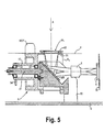
- FIGS. 5 and 6 An alternative embodiment is described below in connection with FIGS. 5 and 6 shown for an image capture device according to the invention.
- a sample window 100 with an integrated sample carrier can be brought into the film plane F of FIG. 5 by rotating the rotor.
- the sharpness of the image can be checked and, if necessary, by means of the CCD 6 the position of the lens 5 can be changed until a sharp Figure is given.
- the pattern window 100 is removed from the film plane again (Reference position) removed by turning the rotor again until a Mask M1 or M2 (in Fig. 6 the mask M1) are in the reference position for the Figure is located.
- a film F can be fed again, which then is sharply imaged on the CCD.
- the pattern captured by the CCD is used to determine the focus by a CPU compared to a reference pattern.
- An adjustment mechanism is preferably used to change the position of the objective 5 provided with a motor (not shown) which is controlled by control electronics the results of the focus determination are taken into account.
- FIG. 5 shows an exemplary construction for the image capture device from the film plane F to the detector 6.
- the direction of incidence of the light from the light source 3 is indicated by the arrow A.
- the film F is held by a mask M1, which has a support mask 61 and a pressure mask 62, which is arranged a short distance above the support mask and is held resiliently, so that a narrow gap remains between the support mask and the pressure mask, through which the person to be scanned remains Film F is passed through.
- a rotor R is provided on which various masks are held.
- Mounted on a base plate G is a carrier 50, which essentially consists of leg parts (not designated in more detail) that are perpendicular to the base plate and parallel to the base plate.
- the parallel leg parts protrude through the open end face R s of the rotor into the latter.
- the deflecting mirror MR which reflects the light entering in the direction of arrow A, is mounted between the parallel leg parts in such a way that it is inclined at 45 ° to the base plate G.
- a bearing shaft 51 extending parallel to the base plate G is fastened to the free end of the parallel leg parts.
- the rotor R is rotatably mounted on this by means of two ball bearings 52 and a bearing tube 53 formed on the rotor R.
- the bearing tube 53 and thus the rotor R is driven by a motor 55 by means of a drive belt 54.
- the CCD 6 is held by a plate 30.
- FIG. 6 shows a perspective view corresponding to FIG. 5, on which one another mask M2 is recognizable for a different, namely smaller, film format. Furthermore, a magnetic read head MOF for reading the magnetic information is included APS films provided. The rotor together with the film masks forms the positioning mechanism, around different film masks and the sample carrier 100 depending on Bring the need to the reference position specified for the fluoroscopy.
- the rotor R is thus essentially one to the longitudinal direction of the film transport path parallel axis rotatably supported.
- the rotor R points to its Scope of at least two film masks M1, M2 for different film formats as well as the sample carrier with pattern.
- the film masks and the sample carrier 100 are selectively insertable into the film transport path by rotating the rotor R.
Abstract
Description
- Fig. 1
- zeigt eine Prinzipskizze eines Ausführungsbeispiels der erfindungsgemäßen Erfassungsvorrichtung,
- Fig. 2
- zeigt eine Schrägansicht der Filmbühne mit Positioniermechanik der Erfassungsvorrichtung der Fig. 1,
- Fig. 3
- zeigt eine Schrägansicht des Schlittens der Positioniermechanik der Fig. 2,
- Fig. 4
- zeigt den Schlitten der Fig. 3 mit Musterträger,
- Fig. 5
- zeigt einen Querschnitt durch den optischen Abbildungsteil einer weiteren Ausführungsform einer erfindungsgemäßen Erfassungsvorrichtung,
- Fig. 6
- zeigt eine perspektivische Ansicht des Abbildungsteils der Fig. 5.
Claims (10)
- Fotografische Erfassungsvorrichtung zum Erfassen fotografischer Bildinformation von fotografischen Medien mit einer Lichtquelle (3),mit einer Bühne (1) für das fotografische Medium, um für das fotografische Medium (F) eine Referenzposition für die Abbildung des fotografischen Mediums mittels einer Abbildungsoptik (5) auf ein Detektionsmittel (6) vorzugeben, das das von der Lichtquelle (3) stammende und durch das fotografische Medium (F) entsprechend der Bildinformation modulierte Licht detektiert,gekennzeichnet durcheinen Musterträger (40) mit einem Muster zur Kontrolle der Schärfe der Abbildung und einer Positioniermechanik (11,11a;R), die den Musterträger entfernbar zu der Referenzposition bringt, um das Muster durch die Abbildungsoptik (5) auf das Detektionsmittel (6) abzubilden.
- Fotografische Erfassungsvorrichtung nach Anspruch 1, dadurch gekennzeichnet, dass die Positioniermechanik (11,11a) ausgebildet ist, um bei der Referenzposition einen Austausch zwischen mindestens einer Maske, die das fotografische Medium bei der Referenzposition festhalten kann, und dem Musterträger vorzunehmen.
- Fotografische Erfassungsvorrichtung nach Anspruch 2, dadurch gekennzeichnet, dass die Positioniermechanik einen Schieber (11) oder Rotor (R) aufweist, auf dem die mindestens eine Maske (16,17;M1,M2) und der Musterträger angeordnet sind, wobei durch Verändern der Lage des Schiebers oder der Drehstellung des Rotors entweder die mindestens eine Maske oder der Musterträger bei der Referenzposition positionierbar ist.
- Fotografische Erfassungsvorrichtung nach Anspruch 1 bis 3, dadurch gekennzeichnet, dass mindestens zwei Masken vorgesehen sind, wobei der Musterträger zwischen zwei Masken angeordnet ist.
- Fotografische Erfassungsvorrichtung nach Anspruch 1 bis 4, dadurch gekennzeichnet, dass der Musterträger ein transparentes Substrat aufweist, das das Muster trägt, wobei das Muster in einer Ebene liegt und zumindest in etwa die Dicke einer fotografischen Schicht eines fotografischen Films aufweist, wobei die Ebene, in der das Muster liegt, mittels der Positioniermechanik zur Schärfenkontrolle in einer vorgegebenen Referenzebene platziert wird.
- Fotografische Erfassungsvorrichtung nach Anspruch 1 bis 5, dadurch gekennzeichnet, dass der Musterträger ein Substrat aufweist, auf dem sich das Muster befindet, wobei der Musterträger bei der Referenzposition durch die Positioniermechanik so angeordnet wird, dass das Substrat der Lichtquelle und das Muster dem Detektionsmittel zugewandt ist.
- Fotografische Erfassungsvorrichtung nach Anspruch 1 bis 6, dadurch gekennzeichnet, dass das Detektionsmittel eine fotoelektrische Wandlereinrichtung (CCD), eine Ausleseelektronik und eine Datenverarbeitungseinrichtung zur-Auswertung der mittels der Ausleselektronik von der Wandlereinrichtung ausgelesenen Signale aufweist, wobei die Datenverarbeitungseinrichtung die Schärfe des abgebildeten Musters bewertet.
- Fotografische Erfassungsvorrichtung nach Anspruch 7, gekennzeichnet durch eine Scharfstellungs-Regelungseinrichtung, die basierend auf der Schärfenbewertung der Datenverarbeitungseinrichtung zur Scharfstellung der Abbildung das Verhältnis des Abstandes von Bühne zu Abbildungsoptik zu dem Abstand von Abbildungsoptik zu Detektionsmittel ändert.
- Fotografische Erfassungsvorrichtung nach Anspruch 8, dadurch gekennzeichnet, dass die Datenverarbeitungseinrichtung eine Bewertung der Schärfe für verschiedene Spektralbereiche des detektierten Lichts gesondert durchführt und die Scharfstellungs-Regelungseinrichtung die Scharfstellung basierend auf den für die verschiedenen Spektralbereiche durchgeführten Schärfenbewertungen optimiert.
- Fotografischer Printer oder Scanner mit einer fotografischen Erfassungsvorrichtung nach einem der Ansprüche 1 bis 9.
Priority Applications (5)
| Application Number | Priority Date | Filing Date | Title |
|---|---|---|---|
| DE50003539T DE50003539D1 (de) | 2000-06-23 | 2000-06-23 | Schärfenkontrolle in einer fotografischen Reproduktionsvorrichtung |
| EP00113039A EP1168058B1 (de) | 2000-06-23 | 2000-06-23 | Schärfenkontrolle in einer fotografischen Reproduktionsvorrichtung |
| CA002348310A CA2348310A1 (en) | 2000-06-23 | 2001-05-24 | Photographic scanner with focus control |
| US09/884,758 US6532058B2 (en) | 2000-06-23 | 2001-06-19 | Photographic scanner with focus control |
| JP2001191647A JP2002062593A (ja) | 2000-06-23 | 2001-06-25 | 焦点制御機能を備えたフォトグラフィックスキャナ |
Applications Claiming Priority (1)
| Application Number | Priority Date | Filing Date | Title |
|---|---|---|---|
| EP00113039A EP1168058B1 (de) | 2000-06-23 | 2000-06-23 | Schärfenkontrolle in einer fotografischen Reproduktionsvorrichtung |
Publications (2)
| Publication Number | Publication Date |
|---|---|
| EP1168058A1 true EP1168058A1 (de) | 2002-01-02 |
| EP1168058B1 EP1168058B1 (de) | 2003-09-03 |
Family
ID=8169023
Family Applications (1)
| Application Number | Title | Priority Date | Filing Date |
|---|---|---|---|
| EP00113039A Expired - Lifetime EP1168058B1 (de) | 2000-06-23 | 2000-06-23 | Schärfenkontrolle in einer fotografischen Reproduktionsvorrichtung |
Country Status (5)
| Country | Link |
|---|---|
| US (1) | US6532058B2 (de) |
| EP (1) | EP1168058B1 (de) |
| JP (1) | JP2002062593A (de) |
| CA (1) | CA2348310A1 (de) |
| DE (1) | DE50003539D1 (de) |
Cited By (1)
| Publication number | Priority date | Publication date | Assignee | Title |
|---|---|---|---|---|
| WO2020185300A1 (en) * | 2019-03-14 | 2020-09-17 | Raytheon Company | Optical element switching systems for an electro optical system |
Citations (9)
| Publication number | Priority date | Publication date | Assignee | Title |
|---|---|---|---|---|
| US4531830A (en) * | 1982-09-16 | 1985-07-30 | Minolta Camera Kabushiki Kaisha | Automatic focusing device for an enlarger |
| US4887125A (en) * | 1987-03-05 | 1989-12-12 | Fuji Photo Film Co., Ltd. | Method of and device for detecting focusing condition of image incident upon image sensor |
| JPH02232640A (ja) * | 1989-03-06 | 1990-09-14 | Fuji Photo Film Co Ltd | 写真焼付機のオートフォーカス装置 |
| JPH02295370A (ja) * | 1989-05-10 | 1990-12-06 | Canon Inc | 画像読取装置 |
| US5005967A (en) * | 1988-07-01 | 1991-04-09 | Minolta Camera Kabushiki Kaisha | Microfilm image processing apparatus having automatic focus control capabilities |
| US5394205A (en) * | 1990-11-29 | 1995-02-28 | Nikon Corporation | Image reading apparatus |
| JPH08292502A (ja) * | 1995-04-25 | 1996-11-05 | Fuji Photo Optical Co Ltd | 写真焼付装置 |
| US5717500A (en) * | 1994-11-17 | 1998-02-10 | Nikon Corporation | Image input device and method |
| US6040891A (en) * | 1997-05-14 | 2000-03-21 | Konica Corporation | Photographic printing apparatus |
Family Cites Families (4)
| Publication number | Priority date | Publication date | Assignee | Title |
|---|---|---|---|---|
| DK0534035T3 (da) * | 1991-09-26 | 1996-06-03 | Gretag Imaging Ag | Fotografisk kopieringsapparat og fremgangsmåde til drift heraf |
| CA2136250C (en) * | 1993-11-22 | 2000-06-06 | Keiji Hashizume | Film transporting apparatus and film processing system using the same |
| US5565912A (en) * | 1994-02-16 | 1996-10-15 | Eastman Kodak Company | Film positioning system using dual perforation sensors |
| US5552855A (en) * | 1995-04-21 | 1996-09-03 | Eastman Kodak Company | Detecting apparatus for finding a reference exposure made on a leading and/or trailing portion of a filmstrip |
-
2000
- 2000-06-23 EP EP00113039A patent/EP1168058B1/de not_active Expired - Lifetime
- 2000-06-23 DE DE50003539T patent/DE50003539D1/de not_active Expired - Fee Related
-
2001
- 2001-05-24 CA CA002348310A patent/CA2348310A1/en not_active Abandoned
- 2001-06-19 US US09/884,758 patent/US6532058B2/en not_active Expired - Fee Related
- 2001-06-25 JP JP2001191647A patent/JP2002062593A/ja active Pending
Patent Citations (9)
| Publication number | Priority date | Publication date | Assignee | Title |
|---|---|---|---|---|
| US4531830A (en) * | 1982-09-16 | 1985-07-30 | Minolta Camera Kabushiki Kaisha | Automatic focusing device for an enlarger |
| US4887125A (en) * | 1987-03-05 | 1989-12-12 | Fuji Photo Film Co., Ltd. | Method of and device for detecting focusing condition of image incident upon image sensor |
| US5005967A (en) * | 1988-07-01 | 1991-04-09 | Minolta Camera Kabushiki Kaisha | Microfilm image processing apparatus having automatic focus control capabilities |
| JPH02232640A (ja) * | 1989-03-06 | 1990-09-14 | Fuji Photo Film Co Ltd | 写真焼付機のオートフォーカス装置 |
| JPH02295370A (ja) * | 1989-05-10 | 1990-12-06 | Canon Inc | 画像読取装置 |
| US5394205A (en) * | 1990-11-29 | 1995-02-28 | Nikon Corporation | Image reading apparatus |
| US5717500A (en) * | 1994-11-17 | 1998-02-10 | Nikon Corporation | Image input device and method |
| JPH08292502A (ja) * | 1995-04-25 | 1996-11-05 | Fuji Photo Optical Co Ltd | 写真焼付装置 |
| US6040891A (en) * | 1997-05-14 | 2000-03-21 | Konica Corporation | Photographic printing apparatus |
Non-Patent Citations (3)
| Title |
|---|
| PATENT ABSTRACTS OF JAPAN vol. 014, no. 547 (P - 1138) 5 December 1990 (1990-12-05) * |
| PATENT ABSTRACTS OF JAPAN vol. 015, no. 078 (E - 1037) 22 February 1991 (1991-02-22) * |
| PATENT ABSTRACTS OF JAPAN vol. 1997, no. 03 31 March 1997 (1997-03-31) * |
Cited By (2)
| Publication number | Priority date | Publication date | Assignee | Title |
|---|---|---|---|---|
| WO2020185300A1 (en) * | 2019-03-14 | 2020-09-17 | Raytheon Company | Optical element switching systems for an electro optical system |
| US11112578B2 (en) | 2019-03-14 | 2021-09-07 | Raytheon Company | Optical element switching systems for an electro optical system |
Also Published As
| Publication number | Publication date |
|---|---|
| DE50003539D1 (de) | 2003-10-09 |
| CA2348310A1 (en) | 2001-12-23 |
| US20010055106A1 (en) | 2001-12-27 |
| US6532058B2 (en) | 2003-03-11 |
| EP1168058B1 (de) | 2003-09-03 |
| JP2002062593A (ja) | 2002-02-28 |
Similar Documents
| Publication | Publication Date | Title |
|---|---|---|
| DE2520481C2 (de) | Vorrichtung zum automatischen Vergleich zweier Muster, insbesondere zum Vergleich von zwei Fingerabdrücken | |
| DE3538822A1 (de) | Vorrichtung zum herstellen fotografischer abzuege sowie verfahren zum erkennen und positionieren von einzelbildern | |
| DE19642901A1 (de) | Abtastgerät mit mehreren Auflösungen | |
| EP0746800B1 (de) | Verfahren und vorrichtung zur photomechanischen herstellung strukturierter oberflächen, insbesondere zum belichten von offsetdruckplatten | |
| EP0393659A2 (de) | Abbildungsverfahren und -vorrichtung | |
| CH683568A5 (de) | Verfahren zum Maskieren von fotografischen Aufzeichnungen. | |
| DE10306104A1 (de) | Vorrichtung und Verfahren zur Erkennung der Kante eines Aufzeichnungsmaterials | |
| JP3122332B2 (ja) | フィルム走査装置 | |
| EP1168058B1 (de) | Schärfenkontrolle in einer fotografischen Reproduktionsvorrichtung | |
| EP0925679B1 (de) | Verfahren und vorrichtung zur digitalen erfassung von sowohl transparenten als auch lichtundurchlässigen dokumentenvorlagen | |
| DE19728200C2 (de) | Abbildungssystem | |
| EP0824218B1 (de) | Vorrichtung zum Bearbeiten von fotographischen Filmen | |
| DE3203851C2 (de) | ||
| US6222612B1 (en) | Process and device for the output of electronic image signals, and a photographic copier | |
| KR0181582B1 (ko) | 사진인화장치 | |
| DE19805048C2 (de) | Verfahren und Vorrichtung zum digitalen Erfassen fotografischer Filme | |
| EP0408697B1 (de) | Gerät zum punktweisen ausmessen von farbigen kopiervorlagen | |
| US6292252B1 (en) | Apparatus for producing a photographic picture | |
| EP1072945B1 (de) | Fotoelektrische Abtastvorrichtung für ein fotografisches Kopiergerät | |
| DE4135128A1 (de) | Gross- und mittelformatkamera mit integrierten mess-, transport-, bildwandler- und anzeigekomponenten | |
| DE4031418A1 (de) | Abtastaufnahmevorrichtung und plattenherstellungsverfahren | |
| US6606170B1 (en) | Apparatus for the manufacture of a photographic print | |
| DE2602545B2 (de) | Kopiergerät zur wahlweisen Anfertigung von Kopien von unterschiedlichen Vorlagen | |
| DE1547305C (de) | Lichtprojektionsvorrichtung für Daten-Aufzeichnungsgeräte, Zeichenmaschinen o. dgl | |
| EP0697629A1 (de) | Verfahren und Vorrichtung zur Erzeugung von Index-Prints auf bzw. mit einem photographischen Printer |
Legal Events
| Date | Code | Title | Description |
|---|---|---|---|
| PUAI | Public reference made under article 153(3) epc to a published international application that has entered the european phase |
Free format text: ORIGINAL CODE: 0009012 |
|
| AK | Designated contracting states |
Kind code of ref document: A1 Designated state(s): AT BE CH CY DE DK ES FI FR GB GR IE IT LI LU MC NL PT SE Kind code of ref document: A1 Designated state(s): CH DE FR GB IT LI |
|
| AX | Request for extension of the european patent |
Free format text: AL;LT;LV;MK;RO;SI |
|
| 111Z | Information provided on other rights and legal means of execution |
Free format text: 20020102 AT BE CH CY DE DK ES FI FR GB GR IE IT LI LU MC NL PT SE |
|
| 17P | Request for examination filed |
Effective date: 20020604 |
|
| RAP1 | Party data changed (applicant data changed or rights of an application transferred) |
Owner name: IMIP LLC |
|
| AKX | Designation fees paid |
Free format text: CH DE FR GB IT LI |
|
| GRAH | Despatch of communication of intention to grant a patent |
Free format text: ORIGINAL CODE: EPIDOS IGRA |
|
| GRAH | Despatch of communication of intention to grant a patent |
Free format text: ORIGINAL CODE: EPIDOS IGRA |
|
| GRAA | (expected) grant |
Free format text: ORIGINAL CODE: 0009210 |
|
| AK | Designated contracting states |
Kind code of ref document: B1 Designated state(s): CH DE FR GB IT LI |
|
| REG | Reference to a national code |
Ref country code: GB Ref legal event code: FG4D Free format text: NOT ENGLISH |
|
| REG | Reference to a national code |
Ref country code: CH Ref legal event code: EP |
|
| GBT | Gb: translation of ep patent filed (gb section 77(6)(a)/1977) | ||
| REG | Reference to a national code |
Ref country code: CH Ref legal event code: NV Representative=s name: RIEDERER HASLER & PARTNER PATENTANWAELTE AG |
|
| REF | Corresponds to: |
Ref document number: 50003539 Country of ref document: DE Date of ref document: 20031009 Kind code of ref document: P |
|
| REG | Reference to a national code |
Ref country code: IE Ref legal event code: FG4D Free format text: GERMAN |
|
| REG | Reference to a national code |
Ref country code: IE Ref legal event code: FD4D |
|
| PGFP | Annual fee paid to national office [announced via postgrant information from national office to epo] |
Ref country code: GB Payment date: 20040528 Year of fee payment: 5 |
|
| PGFP | Annual fee paid to national office [announced via postgrant information from national office to epo] |
Ref country code: CH Payment date: 20040602 Year of fee payment: 5 |
|
| ET | Fr: translation filed | ||
| PGFP | Annual fee paid to national office [announced via postgrant information from national office to epo] |
Ref country code: DE Payment date: 20040604 Year of fee payment: 5 |
|
| PGFP | Annual fee paid to national office [announced via postgrant information from national office to epo] |
Ref country code: FR Payment date: 20040609 Year of fee payment: 5 |
|
| PLBE | No opposition filed within time limit |
Free format text: ORIGINAL CODE: 0009261 |
|
| STAA | Information on the status of an ep patent application or granted ep patent |
Free format text: STATUS: NO OPPOSITION FILED WITHIN TIME LIMIT |
|
| 26N | No opposition filed |
Effective date: 20040604 |
|
| PG25 | Lapsed in a contracting state [announced via postgrant information from national office to epo] |
Ref country code: IT Free format text: LAPSE BECAUSE OF NON-PAYMENT OF DUE FEES Effective date: 20050623 Ref country code: GB Free format text: LAPSE BECAUSE OF NON-PAYMENT OF DUE FEES Effective date: 20050623 |
|
| PG25 | Lapsed in a contracting state [announced via postgrant information from national office to epo] |
Ref country code: LI Free format text: LAPSE BECAUSE OF NON-PAYMENT OF DUE FEES Effective date: 20050630 Ref country code: CH Free format text: LAPSE BECAUSE OF NON-PAYMENT OF DUE FEES Effective date: 20050630 |
|
| PG25 | Lapsed in a contracting state [announced via postgrant information from national office to epo] |
Ref country code: DE Free format text: LAPSE BECAUSE OF NON-PAYMENT OF DUE FEES Effective date: 20060103 |
|
| REG | Reference to a national code |
Ref country code: CH Ref legal event code: PL |
|
| PG25 | Lapsed in a contracting state [announced via postgrant information from national office to epo] |
Ref country code: FR Free format text: LAPSE BECAUSE OF NON-PAYMENT OF DUE FEES Effective date: 20060228 |
|
| GBPC | Gb: european patent ceased through non-payment of renewal fee |
Effective date: 20050623 |
|
| REG | Reference to a national code |
Ref country code: FR Ref legal event code: ST Effective date: 20060228 |