EP1163388B2 - Von vorn beschickbare waschmaschine - Google Patents
Von vorn beschickbare waschmaschine Download PDFInfo
- Publication number
- EP1163388B2 EP1163388B2 EP00912592A EP00912592A EP1163388B2 EP 1163388 B2 EP1163388 B2 EP 1163388B2 EP 00912592 A EP00912592 A EP 00912592A EP 00912592 A EP00912592 A EP 00912592A EP 1163388 B2 EP1163388 B2 EP 1163388B2
- Authority
- EP
- European Patent Office
- Prior art keywords
- motor
- rear wall
- washing machine
- shaft
- machine according
- Prior art date
- Legal status (The legal status is an assumption and is not a legal conclusion. Google has not performed a legal analysis and makes no representation as to the accuracy of the status listed.)
- Expired - Lifetime
Links
Images

Classifications
-
- H—ELECTRICITY
- H02—GENERATION; CONVERSION OR DISTRIBUTION OF ELECTRIC POWER
- H02K—DYNAMO-ELECTRIC MACHINES
- H02K7/00—Arrangements for handling mechanical energy structurally associated with dynamo-electric machines, e.g. structural association with mechanical driving motors or auxiliary dynamo-electric machines
- H02K7/10—Structural association with clutches, brakes, gears, pulleys or mechanical starters
- H02K7/1004—Structural association with clutches, brakes, gears, pulleys or mechanical starters with pulleys
-
- D—TEXTILES; PAPER
- D06—TREATMENT OF TEXTILES OR THE LIKE; LAUNDERING; FLEXIBLE MATERIALS NOT OTHERWISE PROVIDED FOR
- D06F—LAUNDERING, DRYING, IRONING, PRESSING OR FOLDING TEXTILE ARTICLES
- D06F37/00—Details specific to washing machines covered by groups D06F21/00 - D06F25/00
- D06F37/30—Driving arrangements
- D06F37/304—Arrangements or adaptations of electric motors
Definitions
- the invention relates to one of the feedable washing machine with a within a standing with the rear wall of the tub in a fixed connection bearing sleeve over a shaft mounted laundry drum, which is driven by an arranged behind the rear wall of the tub motor.
- a DC external rotor motor for the direct drive of a laundry drum in a laundry machine is known, the rotor via a gear, for example in the manner of a planetary gear, drives the drive shaft of the laundry drum.
- a gear for example in the manner of a planetary gear
- An electric drive motor is known, which is attached via support arm to a vibrating housing and drives via transmission belt on a pulley of a tub.
- the GB 2 104 110 A shows a fixed outside the periphery of a tub drive motor.
- drive motors for driving stored in lye containers laundry drums known, which are arranged behind the rear wall of the tub, but are not connected to the rear wall of the tub.
- a particular advantage of the invention is that the laundry drum is driven by a motor having a lower torque compared to a direct drive.
- the reduction of the torque is achieved by a transmission, however, in contrast to a concentric with the drive shaft arranged motor and an associated likewise concentrically arranged gear, as shown in DE 39 27 426 A1 is known, leads to a reduction of the space for the drive.
- the lower material cost for the engine in contrast to direct drive motors in contrast to direct drive motors.
- the tolerances in the air gap can be better controlled than in direct drive, whereby the efficiency and the engine noise can be influenced favorably.
- the motor is arranged on the support member. This is formed by extending from the center formed by the drum shaft outwardly extending arms, wherein on one of the arms of the motor is arranged.
- the arm supporting the motor is circularly widened in the plane coplanar with the rear wall of the tub, so that the motor extends completely in the region of a support arm of the support part when viewed from above on the rear wall of the tub and of the support star.
- the support member preferably has a U-shaped from the rear wall of the tub weg umandes profile, through which it receives a higher rigidity. Preferably, this U-shaped profile also encloses the circular bulge in the arm receiving the motor. In another embodiment, the U-shaped profile for receiving the motor faces the rear wall of the tub.
- the motor according to the invention is used when the laundry drum and the tub receiving them are arranged with a slight inclination, for example of about 10 ° or 15 °, relative to the horizontal in the washing machine, wherein the front side equipped with the filling opening of the tub is higher than the back wall.
- the motor is arranged below the drum shaft, so that the upper edge of the rear wall of the tub is located near the rear wall of the washing machine housing and below the located in the middle of the back wall of the tub of the washing tub shaft enough space between the rear wall of the tub and the rear wall of the housing is to receive the engine.
- the stator and magnetic poles of the rotor are arranged either axially or radially to each other.
- the torque of the engine is transmitted via a gear to the drum shaft.
- the gearbox is either a toothed belt or a V-belt in conjunction with appropriate pulleys into consideration or a Zahnradgetnebe. in particular with helical gears.
- a chain can be used to transmit the movement of a mounted on the motor shaft pinion on a mounted on the drum shaft sprocket
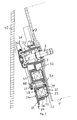
- a tub 1 ( FIG. 2 and 3 ) of a washing machine has a laundry drum (not shown) rotating in it, which has a horizontal ( Fig.2 ) or inclined ( Fig. 3 ) lying wave 2 is flying in the tub 1 is stored. It is possible to realize inclinations of, for example, 10 ° or 15 ° with respect to the horizontal; It is understood that according to the invention, larger inclinations can be selected.
- the shaft 2 of the laundry drum is mounted in a support member 3. This has a bearing bush 4, the bearing 5 and 6, for example, ball bearings, receives, in which the shaft 2 is mounted.
- a ring seal 7 is provided, which surrounds the shaft 2 in the region of the rear wall 8 of the tub 1.
- the support member 3 is fixedly connected to the rear wall 8, for example via screw.
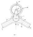
- the support member 3 has star-shaped from the center of the rear wall 8 outgoing arms 9, 10 and 11 ( FIG. 1 ) on.
- the arms 9 to 11 each have a U-shaped profile and, in addition to a resting on the rear wall 8 wall 12 perpendicular to the rear wall 8 repellent side walls 13 and 14.
- the arm 11 has a cup-shaped widening 17 for receiving a motor 16.
- the support member 3 In the middle of the widening 17, the support member 3 has a facing away from the rear wall 8 flange 18 for receiving the motor shaft 19, which is mounted in the flange 18 via bearings 20 and 21.
- stator 22 At the flange 18 stator 22 are fixed, the excitation windings 23 carry.
- the stator 22 are on the inner wall of a bell-shaped, the rotor of the motor 16 forming flange 24 fixed magnetic poles 25 in the radial direction opposite.
- the stator packs may also be disposed on the wall of the support member 3 extending along the back wall 8 and the magnetic poles 25 may be mounted on the bottom of the flange 24 substantially coplanar with this wall.
- the flange 24 is mounted on a shaft extension 26 forming the extension of the motor shaft 19.
- the shaft journal 26 also serves to receive a pulley 27 for a V-ribbed belt 28.
- the flange 24 at least partially covers upwards and laterally, penetration of dirt particles in the area between the stator 22 and the poles 25 is effectively prevented.
- the formed by the wall 12 and the side walls 13 to 15 U-shaped profile gives the arms 9 to 11 high stability.
- FIG. 3 Drive device shown a motor 32 arranged on the rear wall 8 of the tub 1 facing side of a support member 33.
- the support member 33 is also star-shaped as the support member 3, however, has in the region of its a cup-shaped broadening 34a having support arm 34 has a different structure than the support member 3.
- the support arm 34 consists of a plate and a perpendicular standing on this, substantially circular
- the motor 32 is constructed in the same manner as the motor 16, as indicated by the use of the same reference numerals. Also in this case, the stator and the poles can be arranged in the axial direction.
- the motor 32 drives a V-ribbed belt 41 via a motor shaft 37, which is mounted in a bearing 38 forming its bearing sleeve flange 38 of the support arm 34, a V-ribbed belt 41 in the same manner as the motor 16, the V-ribbed belt 28th
- a drive device is provided with an indirect drive for the shaft 2, so that this compared to a directly driving the shaft 2 motor, as he from the DE 195 47 745 A1 It is known that only a lower torque needs to be applied.
- the rotational speed of the motor shaft 19 and 37 in the ratio of, for example, 3: 1 or 4: 1 reduced. In this way, a motor can be built with less material than is the case with a direct drive.
- External rotor motors shown can also be used internal rotor motors, which have the same size, ie the arrangement of the air gap at the same place a smaller rotor and thus a lower Torque can muster as the external rotor motor. Because the motor 16 or 32 is arranged in the area behind the rear wall 8 of the tub 1 due to its compact construction, the space below the tub 1 for other facilities of the washing machine is available.
- motor 16, 32 can be both an asynchronous motor, a DC motor or a reluctance motor provide.
- the asynchronous motor is controlled by a frequency converter
- the DC motor is a brushless, controlled by a power converter, electronically commutated motor. Due to the converter drive, the motors 16, 32 can be controlled in a positionally exact manner and decelerated to the exact position.
- the spatial resolution of the Abbremsposition of the motor 16, 32 of ⁇ 3 ° results in a reduction ratio of 3: 1 a drum position resolution of ⁇ 1 °.
- the spatial resolution is still increased by the reduction gear.
- a precise spatial resolution can be achieved in particular when using a gear transmission, in particular with helical gears, as well as when using a toothed belt instead of a simple V-belt or V-ribbed belt.
- the V-ribbed belt 28, 41 or a corresponding V-belt or toothed belt on the outer wall 31 of the flange 30 has a larger wrap angle and can thus be made narrower than in a conventional drive.
- the engine 16 is as in FIG. 2 shown, arranged on a separate support member 3.
- FIG. 3 A particularly advantageous construction of the washing machine results when these, as in Fig. 3 shown. one with the filling upwardly inclined relative to the horizontal washing drum and an equally inclined shaft 2, so that the rear wall 8 is also inclined relative to the vertical and the motor 16, 32 below the shaft 2 in the region between the rear wall 8 and the rear wall 42 of the washing machine is arranged. This results in an extremely space-saving storage of the motor 16, 32nd
- a drive device for one of the feedable washing machine with a within a standing with the rear wall 8 of the tub 1 in a fixed connection bearing sleeve 4 via a substantially horizontally disposed shaft 2 mounted laundry drum is arranged by a likewise behind the back 8 of the tub 1 motor 16 , 32 driven.
- the motor 16, 32 outside the center formed by the shaft 2 of the rear wall 8 but arranged behind this. It transmits its torque via a gear, which is formed for example by a disc 27 and a V-ribbed belt 28, 41, on the shaft second
Landscapes
- Engineering & Computer Science (AREA)
- Textile Engineering (AREA)
- Power Engineering (AREA)
- Main Body Construction Of Washing Machines And Laundry Dryers (AREA)
- Detail Structures Of Washing Machines And Dryers (AREA)
- Treatment Of Water By Ion Exchange (AREA)
- Crushing And Pulverization Processes (AREA)
- Cleaning By Liquid Or Steam (AREA)
Description
- Die Erfindung bezieht sich auf eine von vom beschickbare Waschmaschine mit einer innerhalb einer mit der Rückwand des Laugenbehälters in fester Verbindung stehenden Lagerhülse über eine Welle fliegend gelagerten Wäschetrommel, die durch einen hinter der Rückwand des Laugenbehälters angeordneten Motor angetrieben ist.
- Aus der
DE 195 47 745 A1 ist eine derartige Antriebsvorrichtung bereits bekannt. In dieser Antriebsvorrichtung ist die horizontal liegende Welle der Wäschetrommel an ihrem äußeren Ende mit dem Läufer des Motors drehfest verbunden. Der Motor treibt somit direkt auf die Welle der Wäschetrommel. Dadurch, daß der Motor die Wäschetrommel direkt antreibt, muß er ein verhältnismäßig hohes Drehmoment aufbringen, um diese in Bewegung zu setzen. - Aus der
DE 39 27 426 A1 ist ein Gleichstrom-Außenläufermotor für den Direktantrieb einer Wäschetrommel in einer Wäschebehandtungsmaschine bekannt, dessen Rotor über ein Getriebe, beispielsweise nach Art eines Planetengetriebes, die Antriebswelle der Wäschetrommel antreibt. Dadurch, daß das Getriebe zwischen dem Motor und der Rückwand der Waschmaschine angebracht ist, wird zusätzlicher Platz benötigt, der dann für die Wäschetrommel nicht zur Verfügung steht. - Aus der
LU 37 211 GB 2 104 110 A US 2 687 861 und aus derEP 0 354 158 A2 sind Antriebsmotoren zum Antrieb von in Laugenbehältern gelagerten Wäschetrommeln bekannt, die hinter der Rückwand des Laugenbehälters angeordnet sind, jedoch nicht mit der Rückwand des Laugenbehälters verbunden sind. - Es ist die Aufgabe der Erfindung, eine von vorn beschickbare Waschmaschine derart zu verbessern, dass der Motor platzsparend angeordnet ist.
- Diese Aufgabe wird erfindungsgemäß durch die Merkmale von Anspruch 1 gelöst.
- Ein besonderer Vorteil der Erfindung besteht darin, daß die Wäschetrommel durch einen Motor angetrieben wird, der ein gegenüber einem Direktantrieb niedrigeres Drehmoment aufweist. Die Reduktion des Drehmoments wird durch ein Getriebe erreicht, das jedoch im Unterschied zu einem konzentrisch zur Antriebswelle angeordneten Motor und einem zugehörigen ebenfalls konzentrisch angeordneten Getriebe, wie aus der
DE 39 27 426 A1 bekannt ist, zu einer Verringerung des Bauraums für den Antrieb führt. - Besonders vorteilhaft beim erfindungsgemäßen Antrieb ist der geringere Materialaufwand für den Motor im Gegensatz zu Direktantriebsmotoren. Beim erfindungsgemäßen Antrieb können außerdem die Toleranzen im Luftspalt besser als beim Direktantrieb beherrscht werden, womit der Wirkungsgrad und das Motorgeräusch günstig beeinflußbar sind..
- Ein weiterer Vorteil der Erfindung besteht darin, daß der Motor auf dem Tragteil angeordnet ist. Dieses ist durch von der durch die Trommelwelle gebildeten Mitte nach außen sich erstreckende Arme ausgebildet, wobei auf einem der Arme der Motor angeordnet wird. Der den Motor tragende Arm ist kreisförmig in der zur Rückwand des Laugenbehälters koplanaren Ebene aufgeweitet, so daß sich bei Draufsicht auf die Rückwand des Laugenbehälters sowie des Tragsterns der Motor ganz im Bereich eines Tragarms des Tragteils erstreckt. Das Tragteil weist vorzugsweise ein U-förmig von der Rückwand des Laugenbehälters wegweisendes Profil auf, durch das es eine höhere Steifigkeit erhält. Vorzugsweise umschließt dieses U-förmige Profil auch die kreisförmige Ausbuchtung in dem den Motor aufnehmenden Tragarm. In einem anderen Ausführungsbeispiel ist das U-förmige Profil für die Aufnahme des Motors der Rückwand des Laugenbehälters zugewandt.
- In besonders vorteilhafter Weise kommt der erfindungsgemäße Motor zum Einsatz, wenn die Wäschetrommel und der sie aufnehmende Laugenbehälter mit einer leichten Neigung, beispielsweise von ca. 10° oder 15°, gegenüber der Horizontalen in der Waschmaschine angeordnet sind, wobei die mit der Befüllungsöffnung ausgestattete Vorderseite des Laugenbehälters höher liegt als die Rückwand. In diesem Fall wird der Motor unterhalb der Trommelwelle angeordnet, so daß sich die obere Kante der Rückwand des Laugenbehälters in der Nähe der Rückwand des Waschmaschinengehäuses befindet und unterhalb der in der Mitte der Rückwand des Laugenbehälters befindlichen Welle der Wäschetrommel genügend Platz zwischen der Rückwand des Laugenbehälters und der Rückwand des Gehäuses ist, um den Motor aufzunehmen.
- Die Statorpakete und die Magnetpole des Rotors sind entweder axial oder radial zueinander angeordnet. Das Drehmoment des Motors wird über ein Getriebe auf die Trommelwelle übertragen. Als Getriebe kommt entweder ein Zahnriemen oder ein Keilriemen in Verbindung mit entsprechenden Riemenscheiben in Betracht oder ein Zahnradgetnebe. insbesondere mit schräg verzahnten Zahnrädern. Auch eine Kette läßt sich einsetzen, um die Bewegung von einem auf der Motorwelle angebrachten Ritzel auf ein auf der Trommelwelle angebrachtes Kettenrad zu übertragen
- Vorteilhafte Weiterbildungen ergeben sich aus den Unteransprüchen.
- Nachstehend wird die Erfindung anhand der Zeichnungen in Ausführungsbeispielen näher erläutert. Es zeigen:
- Fig. 1
- eine Draufsicht auf ein an der Rückwand des Laugenbehälters angebrachtes Tragteil und eine Antriebsvorrichtung,
- Fig. 2
- die Antriebsvorrichtung und das Tragteil gemäß
Figur 1 im Querschnitt entlang einer Linie AA, - Fig. 3
- eine zweite Ausführungsform der Antriebsvorrichtung für einen geneigt angeordneten Laugenbehälter im Querschnitt, wobei die Läuferglocke der Antriebsvorrichtung an dem Tragteil auf der der Rückwand des Laugenbehälters zugewandten Seite befestigt ist.
- Ein Laugenbehälter 1 (
Figur 2 und3 ) einer Waschmaschine weist eine sich in ihm drehende Wäschetrommel (nicht dargestellt) auf, die über eine horizontal (Fig.2 ) oder geneigt (Fig. 3 ) liegende Welle 2 fliegend in dem Laugenbehälter 1 gelagert ist. Es lassen sich Neigungen von beispielsweise von 10° oder 15° gegenüber der Horizontalen realisieren; es versteht sich, daß gemäß der Erfindung auch größere Neigungen gewählt werden können. Die Welle 2 der Wäschetrommel ist in einem Tragteil 3 gelagert. Dieses weist eine Lagerbuchse 4 auf, die Lager 5 und 6, beispielsweise Kugellager, aufnimmt, in denen die Welle 2 gelagert ist. - Zur Vermeidung des Austretens der Waschlauge aus dem Laugenbehälter 1 ist eine Ringdichtung 7 vorgesehen, die die Welle 2 im Bereich der Rückwand 8 des Laugenbehälters 1 umgibt.
- Das Tragteil 3 ist mit der Rückwand 8 fest verbunden, beispielsweise über Schraubverbindungen. Das Tragteil 3 weist sternförmig von der Mitte der Rückwand 8 ausgehende Arme 9, 10 und 11 (
Figur 1 ) auf. Zur Verstärkung haben die Arme 9 bis 11 jeweils ein U-förmiges Profil und weisen neben einer auf der Rückwand 8 aufliegenden Wand 12 senkrecht von der Rückwand 8 abweisende Seitenwände 13 und 14 auf. - Der Arm 11 weist zur Aufnahme eines Motors 16 eine topfförmige Verbreiterung 17 auf. In der Mitte der Verbreiterung 17 weist das Tragteil 3 einen von der Rückwand 8 wegweisenden Flansch 18 zur Aufnahme der Motorwelle 19 auf, die über Lager 20 und 21 in dem Flansch 18 gelagert ist.
- An dem Flansch 18 sind Statorpakete 22 befestigt, die Erregerwicklungen 23 tragen. Den Statorpaketen 22 stehen an der Innenwand eines glockenförmigen, den Läufer des Motors 16 bildenden Flansches 24 befestigte magnetische Pole 25 in radialer Richtung gegenüber. Anstelle der radialen Anordnung der Statorpakete 22 und der Pole 25 können die Statorpakete auch auf der entlang der Rückwand 8 verlaufenden Wand des Tragteils 3 angeordnet sein und die magnetischen Pole 25 auf dem im wesentlichen zu dieser Wand koplanaren Boden des Flansches 24 befestigt sein. Der Flansch 24 ist auf einem die Verlängerung der Motorwelle 19 bildenden Wellenzapfen 26 befestigt. Der Wellenzapfen 26 dient ebenfalls zur Aufnahme einer Scheibe 27 für einen Keilrippenriemen 28. Dieser überträgt die Drehbewegung des Motors 16 auf einen an einem Wellenzapfen 29 an der Welle 2 befestigten glockenförmigen Flansch 30, über dessen zylindrische Außenwand 31 der Keilrippenriemen 28 umläuft. Es versteht sich, daß anstelle der Außenwand 31 auch eine Keilriemenscheibe vorgesehen sein kann.
- Dadurch, daß die Seitenwand 14 den Flansch 24 wenigstens teilweise nach oben und seitlich überdeckt, wird ein Eindringen von Schmutzpartikeln in den Bereich zwischen den Statorpaketen 22 und den Polen 25 wirksam verhindert.
- Das durch die Wand 12 und die Seitenwände 13 bis 15 gebildete U-förmige Profil verleiht den Armen 9 bis 11 hohe Stabilität.
- Anstelle der in
Figur 1 und2 dargestellten Ausführungsform ist bei der inFigur 3 dargestellten Antriebsvorrichtung ein Motor 32 auf der der Rückwand 8 des Laugenbehälters 1 zugewandten Seite eines Tragteils 33 angeordnet. Das Tragteil 33 ist ebenfalls sternförmig ausgeführt wie das Tragteil 3, weist jedoch im Bereich seines eine topfförmige Verbreiterung 34a aufweisenden Tragarms 34 einen anderen Aufbau auf als das Tragteil 3. Der Tragarm 34 besteht aus einer Platte und einer senkrecht auf dieser stehenden, im wesentlichen kreisförmig um den glockenförmigen Flansch 35 des Motors 32 angeordneten und in Richtung zu der Rückwand 8 weisenden Wand 36. Der Motor 32 ist im übrigen in derselben Weise aufgebaut wie der Motor 16, wie durch die Verwendung derselben Bezugszeichen angezeigt wird. Auch in diesem Fall können die Statorpakete und die Pole in axialer Richtung angeordnet sein. Der Motor 32 treibt über eine Motorwelle 37, die in einem ihre Lagerhülse bildenden Flansch 38 des Tragarms 34 über Lager 39 und 40 gelagert ist, einen Keilrippenriemen 41 in derselben Weise an wie der Motor 16 den Keilrippenriemen 28. - Durch die außermittige Anordnung des Motors 16 oder 32 wird eine Antriebsvorrichtung mit einem indirekten Antrieb für die Welle 2 geschaffen, so daß dieser im Vergleich zu einem direkt die Welle 2 antreibenden Motor, wie er aus der
DE 195 47 745 A1 bekannt ist, nur ein niedrigeres Drehmoment aufzubringen braucht. Durch das Getriebe wird die Drehgeschwindigkeit der Motorwelle 19 bzw. 37 im Verhältnis von beispielsweise 3 : 1 oder 4 : 1 untersetzt. Auf diese Weise kann ein Motor mit geringerem Materialaufwand gebaut werden, als dies bei einem Direktantrieb der Fall ist. - Anstelle der in
Figur 2 und3 dargestellten Außenläufermotoren lassen sich auch Innenläufermotoren verwenden, wobei diese bei gleicher Baugröße, d. h. der Anordnung des Luftspalts an derselben Stelle einen kleineren Läufer haben und somit auch ein niedrigeres Drehmoment aufzubringen vermögen als der Außenläufermotor. Dadurch, daß der Motor 16 bzw. 32 aufgrund seines kompakten Aufbaus im Bereich hinter der Rückwand 8 des Laugenbehälters 1 angeordnet ist, steht der Bauraum unterhalb des Laugenbehälters 1 für andere Einrichtungen der Waschmaschine zur Verfügung. - Als Motor 16, 32 läßt sich sowohl ein Asynchronmotor, ein Gleichstrommotor oder auch ein Reluktanzmotor vorsehen. Der Asynchronmotor wird über einen Frequenzumrichter gesteuert, der Gleichstrommotor ist ein bürstenloser, über einen Stromrichter gesteuerter, elektronisch kommutierter Motor. Durch den Umrichterantrieb lassen sich die Motoren 16, 32 positionsgenau ansteuern und positionsgenau abbremsen. Die Ortsauflösung der Abbremsposition des Motors 16, 32 von ± 3° ergibt bei einem Untersetzungsverhältnis von 3 : 1 eine Trommelpositionsauflösung von ± 1°. Somit wird durch das Untersetzungsgetriebe die Ortspositionsauflösung noch erhöht. Eine genaue Ortsauflösung läßt sich insbesondere bei Verwendung eines Zahnradgetriebes, insbesondere auch mit schräg verzahnten Zahnrädern, erreichen wie auch bei Einsatz eines Zahnriemens anstelle eines einfachen Keilriemens oder des Keilrippenriemens.
- Gegenüber einem konventionellen indirekten Antrieb hat der Keilrippenriemen 28, 41 oder ein entsprechender Keilriemen oder Zahnriemen auf der Außenwand 31 des Flansches 30 einen größeren Umschlingungswinkel und kann somit schmaler ausgeführt werden als bei einem konventionellen Antrieb.
- Der Motor 16 ist wie in
Figur 2 dargestellt, auf einem gesonderten Tragteil 3 angeordnet. - Ein besonders vorteilhafter Aufbau der Waschmaschine ergibt sich dann, wenn diese, wie in
Fig. 3 dargestellt. eine mit der Befüllöffnung nach oben gegenüber der Horizontalen geneigte Wäschetrommel und eine ebenso geneigte Welle 2 aufweist, so daß die Rückwand 8 gegenüber der Vertikalen ebenfalls entsprechend geneigt ist und der Motor 16, 32 unterhalb der Welle 2 im Bereich zwischen der Rückwand 8 und der Rückwand 42 der Waschmaschine angeordnet ist. Dadurch ergibt sich eine außerordentlich platzsparende Unterbringung des Motors 16, 32. - Eine Antriebsvorrichtung für eine von vom beschickbare Waschmaschine mit einer innerhalb einer mit der Rückwand 8 des Laugenbehälters 1 in fester Verbindung stehenden Lagerhülse 4 über eine im wesentlichen horizontal liegende Welle 2 fliegend gelagerten Wäschetrommel wird durch einen ebenfalls hinter der Rückseite 8 des Laugenbehälters 1 angeordneten Motor 16, 32 angetrieben. Dabei ist der Motor 16, 32 außerhalb der durch die Welle 2 gebildeten Mitte der Rückwand 8 aber hinter dieser angeordnet. Er überträgt sein Drehmoment über ein Getriebe, das beispielsweise durch eine Scheibe 27 und einen Keilrippenriemen 28, 41 gebildet ist, auf die Welle 2.
Claims (12)
- Von vom beschickbare Waschmaschine mit einem Laugenbehälter (1) und mit einer Wäschetrommel, die durch einen hinter der Rückwand (8) des Laugenbehälters (1) angeordneten Motor (16, 32) angetrieben wird und die innerhalb einer mit der Rückwand (8) des Laugenbehälters (1) in fester Verbindung stehenden Lagerhülse (4) über eine Welle (2) fliegend gelagert ist, wobei der Motor (16, 32) hinter der Rückwand (8) außerhalb der durch die Welle (2) gebildeten Mitte der Rückwand (8) angeordnet ist, und wobei das von dem Motor (16, 32) erzeugte Drehmoment über ein Getriebe auf die Welle (2) übertragen wird, dadurch gekennzeichnet, dass der Motor (16, 32) an einem an der Rückwand (8) befestigten und hinter dieser angeordneten Tragteil (3, 33) befestigt ist, wobei das Tragteil (3, 33) durch von der Mitte der Rückwand (8) nach außen sich erstreckende Arme (9, 10, 11) ausgebildet und der Motor (16, 32) auf einem dieser Arme (9, 10, 11) angeordnet ist, der eine im wesentlichen topfförmigen Verbreiterung (17) aufweist, die den Motor (16, 32) aufnimmt.
- Waschmaschine nach Anspruch 1, dadurch gekennzeichnet, dass der Motor (16) auf der von der Rückwand (8) abgewandten Seite des Tragteils (3) angeordnet ist.
- Waschmaschine nach Anspruch 1, dadurch gekennzeichnet, dass der Motor (32) an dem Tragteil (3) im Bereich zwischen dem Tragteil (33) und der Rückwand (8) des Laugenbehälters (1) angeordnet ist.
- Waschmaschine nach einem der Ansprüche 1 bis 3, dadurch gekennzeichnet, dass durch den Motor (16, 32) eine Motorwelle (19, 37) und über diese sowie eine auf ihr aufgebrachte Scheibe (27) ein Keilriemen, ein Zahnriemen oder Keilrippenriemen (28, 41) angetrieben wird, wobei der Keilriemen, der Zahnriemen oder der Keilrippenriemen (28,41) seinerseits um eine auf der Welle (2) angeordnete Scheibe oder einen auf ihr angeordneten glockenförmigen Flansch (31) umläuft und diese antreibt.
- Waschmaschine nach einem der Ansprüche 1 bis 3, dadurch gekennzeichnet, dass die Welle (2) der Wäschetrommel über ein Zahnräder, insbesondere schräg verzahnte Zahnräder, aufweisendes Getriebe angetrieben wird.
- Waschmaschine nach einem der Ansprüche 1 bis 5, dadurch gekennzeichnet, dass der Motor (16, 32) als Außenläufermotor ausgebildet ist.
- Waschmaschine nach einem der Ansprüche 1 bis 6, dadurch gekennzeichnet, dass das Tragteil (3, 33) einen die Lagerhülse der Motorwelle (19, 37) bildenden Flansch (18, 38) aufweist, der die Statorpakete (22) trägt.
- Waschmaschine nach einem der Ansprüche 1 bis 7, dadurch gekennzeichnet, dass sich die Statorpakete (22) und die magnetischen Pole (25) des Läufers, bezogen auf die Motorwelle (19, 37) in axialer oder in radialer Richtung, gegenüberstehen.
- Waschmaschine nach einem der Ansprüche 1 bis 8, dadurch gekennzeichnet, dass das Tragteil (3) eine den Läufer des Motors (16, 32) im wesentlichen ringförmig überdeckende Seitenwand (14, 36) aufweist.
- Waschmaschine nach einem der Ansprüche 1 bis 9, dadurch gekennzeichnet, dass der Läufer des Motors (16, 32) als glockenförmiger Flansch (24, 35) ausgebildet ist.
- Waschmaschine nach einem der Ansprüche 1 bis 10, dadurch gekennzeichnet, dass bei mit der Befüllöffnung nach oben geneigter Wäschetrommel der Motor (16, 32) unterhalb der Welle (2) im Bereich zwischen der Rückwand (8) und der Rückwand (42) der Waschmaschine angeordnet ist.
- Waschmaschine nach einem der Ansprüche 1 bis 11, dadurch gekennzeichnet, dass der Motor (16, 32) ein elektronisch kommutierter Gleichstrommotor, ein über einen Frequenz-Umrichter gesteuerter Asynchronmotor oder ein Reluktanzmotor ist.
Priority Applications (1)
| Application Number | Priority Date | Filing Date | Title |
|---|---|---|---|
| SI200030485T SI1163388T1 (en) | 1999-03-12 | 2000-03-10 | Front-loading washing machine |
Applications Claiming Priority (3)
| Application Number | Priority Date | Filing Date | Title |
|---|---|---|---|
| DE19911139A DE19911139A1 (de) | 1999-03-12 | 1999-03-12 | Antriebsvorrichtung für eine von vorn beschickbare Waschmaschine |
| DE19911139 | 1999-03-12 | ||
| PCT/EP2000/002133 WO2000055414A1 (de) | 1999-03-12 | 2000-03-10 | Antriebsvorrichtung für eine von vorn beschickbare waschmaschine |
Publications (3)
| Publication Number | Publication Date |
|---|---|
| EP1163388A1 EP1163388A1 (de) | 2001-12-19 |
| EP1163388B1 EP1163388B1 (de) | 2004-10-13 |
| EP1163388B2 true EP1163388B2 (de) | 2009-08-05 |
Family
ID=7900797
Family Applications (1)
| Application Number | Title | Priority Date | Filing Date |
|---|---|---|---|
| EP00912592A Expired - Lifetime EP1163388B2 (de) | 1999-03-12 | 2000-03-10 | Von vorn beschickbare waschmaschine |
Country Status (7)
| Country | Link |
|---|---|
| US (1) | US6499323B2 (de) |
| EP (1) | EP1163388B2 (de) |
| AT (1) | ATE279563T1 (de) |
| DE (2) | DE19911139A1 (de) |
| ES (1) | ES2230080T3 (de) |
| TR (1) | TR200102429T2 (de) |
| WO (1) | WO2000055414A1 (de) |
Families Citing this family (13)
| Publication number | Priority date | Publication date | Assignee | Title |
|---|---|---|---|---|
| DE10062364A1 (de) * | 2000-12-14 | 2002-06-20 | Bsh Bosch Siemens Hausgeraete | Antriebsvorrichtung für ein Haushaltsgerät und Verfahren zur Montage eines Elektromotors |
| DE10064549A1 (de) * | 2000-12-22 | 2002-06-27 | Bsh Bosch Siemens Hausgeraete | Trommelwaschmaschine mit verbesserter Wasch- oder Spülflüssigkeitszufuhr in die Innentrommel |
| US8256246B2 (en) * | 2003-10-29 | 2012-09-04 | Miele & Cie. Kg. | Aggregate for a washing machine with a plastic sudsing container |
| ES2373781T3 (es) * | 2003-10-29 | 2012-02-08 | Miele & Cie. Kg | Procedimiento para la producción de una unidad de lavado con una cubeta de lavado de plástico. |
| KR20050089355A (ko) * | 2004-03-04 | 2005-09-08 | 엘지전자 주식회사 | 대용량 드럼세탁기용 비엘디시 모터 |
| DE102004049549A1 (de) * | 2004-03-24 | 2005-10-13 | Diehl Ako Stiftung & Co. Kg | Motor als Direktantrieb und Verfahren zur Montage des Motors |
| US7342334B2 (en) * | 2004-10-29 | 2008-03-11 | Emerson Electric Co. | Insulated stator with wire routing element |
| US7685665B2 (en) * | 2006-09-13 | 2010-03-30 | General Electric Company | Washing machine having self-centering drive assembly |
| ITMI20070304U1 (it) | 2007-09-11 | 2009-03-12 | Askoll Holding Srl | Supporto per il fissaggio di un motore elettrico ad una vasca di una lavatrice o simile elettrodomestico |
| DE102010062916A1 (de) | 2010-12-13 | 2012-06-14 | BSH Bosch und Siemens Hausgeräte GmbH | Hausgerät zur Pflege von Wäschestücken |
| DE102012024703A1 (de) * | 2012-12-18 | 2014-06-18 | Robert Bosch Gmbh | Lagerhülse mit Manschette |
| JP2020022277A (ja) * | 2018-08-01 | 2020-02-06 | 日本電産テクノモータ株式会社 | モータ |
| US11124912B2 (en) | 2018-08-09 | 2021-09-21 | Haier Us Appliance Solutions, Inc. | Planetary helical gear train for a transmission assembly of a washing machine appliance |
Citations (6)
| Publication number | Priority date | Publication date | Assignee | Title |
|---|---|---|---|---|
| US2296260A (en) † | 1938-08-26 | 1942-09-22 | Westinghouse Electric & Mfg Co | Apparatus for washing fabrics or the like |
| US2895320A (en) † | 1955-06-15 | 1959-07-21 | Gen Motors Corp | Washer |
| US3111017A (en) † | 1956-11-06 | 1963-11-19 | Hoover Co | Timer control for automatic washing and drying machines |
| DE1933117U (de) † | 1965-08-27 | 1966-02-24 | Beumer K G Geb | Waschmaschine od. dgl. |
| DE3132211C2 (de) † | 1981-08-14 | 1987-12-10 | Licentia Patent-Verwaltungs-Gmbh, 6000 Frankfurt, De | |
| DE19547745A1 (de) † | 1995-12-20 | 1997-06-26 | Bosch Siemens Hausgeraete | Antriebsvorrichtung für eine von vorn beschickbare Waschmaschine |
Family Cites Families (6)
| Publication number | Priority date | Publication date | Assignee | Title |
|---|---|---|---|---|
| US2625031A (en) * | 1948-07-02 | 1953-01-13 | Standard Telephones Cables Ltd | Washing machine provided with resilient collapsible inlet |
| US2687861A (en) * | 1951-07-03 | 1954-08-31 | Itt | Washing machine support |
| LU37211A1 (de) * | 1958-05-23 | |||
| DE1933827B2 (de) * | 1969-07-03 | 1972-10-12 | Danfoss A/S, Nordborg (Dänemark) | Antriebsvorrichtung fuer eine waschmaschine |
| US4914331A (en) * | 1988-08-02 | 1990-04-03 | Emerson Electric Co. | Minimum height motor assembly using aluminum endshields |
| DE3927426B4 (de) * | 1989-08-19 | 2006-02-23 | Ebm-Papst Mulfingen Gmbh & Co. Kg | Antriebseinheit für eine Wäsche-Behandlungsmaschine |
-
1999
- 1999-03-12 DE DE19911139A patent/DE19911139A1/de not_active Withdrawn
-
2000
- 2000-03-10 DE DE2000508233 patent/DE50008233D1/de not_active Expired - Lifetime
- 2000-03-10 TR TR2001/02429T patent/TR200102429T2/xx unknown
- 2000-03-10 WO PCT/EP2000/002133 patent/WO2000055414A1/de active IP Right Grant
- 2000-03-10 ES ES00912592T patent/ES2230080T3/es not_active Expired - Lifetime
- 2000-03-10 AT AT00912592T patent/ATE279563T1/de not_active IP Right Cessation
- 2000-03-10 EP EP00912592A patent/EP1163388B2/de not_active Expired - Lifetime
-
2001
- 2001-09-12 US US09/951,238 patent/US6499323B2/en not_active Expired - Lifetime
Patent Citations (6)
| Publication number | Priority date | Publication date | Assignee | Title |
|---|---|---|---|---|
| US2296260A (en) † | 1938-08-26 | 1942-09-22 | Westinghouse Electric & Mfg Co | Apparatus for washing fabrics or the like |
| US2895320A (en) † | 1955-06-15 | 1959-07-21 | Gen Motors Corp | Washer |
| US3111017A (en) † | 1956-11-06 | 1963-11-19 | Hoover Co | Timer control for automatic washing and drying machines |
| DE1933117U (de) † | 1965-08-27 | 1966-02-24 | Beumer K G Geb | Waschmaschine od. dgl. |
| DE3132211C2 (de) † | 1981-08-14 | 1987-12-10 | Licentia Patent-Verwaltungs-Gmbh, 6000 Frankfurt, De | |
| DE19547745A1 (de) † | 1995-12-20 | 1997-06-26 | Bosch Siemens Hausgeraete | Antriebsvorrichtung für eine von vorn beschickbare Waschmaschine |
Also Published As
| Publication number | Publication date |
|---|---|
| TR200102429T2 (tr) | 2002-01-21 |
| US20020069679A1 (en) | 2002-06-13 |
| WO2000055414A1 (de) | 2000-09-21 |
| US6499323B2 (en) | 2002-12-31 |
| ES2230080T3 (es) | 2005-05-01 |
| EP1163388B1 (de) | 2004-10-13 |
| DE50008233D1 (de) | 2004-11-18 |
| EP1163388A1 (de) | 2001-12-19 |
| ATE279563T1 (de) | 2004-10-15 |
| DE19911139A1 (de) | 2000-09-14 |
Similar Documents
| Publication | Publication Date | Title |
|---|---|---|
| EP1163388B2 (de) | Von vorn beschickbare waschmaschine | |
| DE60318676T2 (de) | Trommelwaschmaschine | |
| DE112008002101B4 (de) | Gurtstrafferantrieb für den Sicherheitsgurt eines Fahrzeugs mit einem Topflager für die Rotorwelle eines Elektromotors | |
| DE69635136T2 (de) | Vorrichtung zum direkten verbinden eines verbrennungsmotors mit einer angetriebenen maschine | |
| WO2000037731A1 (de) | Antriebsvorrichtung für eine von vorn beschickbare wäschebehandlungsmaschine | |
| DE102007031508B4 (de) | Motor und Wischervorrichtung, die den Motor enthält | |
| DE60123306T2 (de) | Miniaturmotor mit Getriebegehäuse | |
| DE3927426A1 (de) | Antriebseinheit fuer eine waesche-behandlungsmaschine | |
| EP0657575B1 (de) | Waschautomat | |
| DE19634629B4 (de) | Getriebelose Antriebsvorrichtung für Aufzüge | |
| EP1618961A1 (de) | Antriebsvorrichtung für Schneckenzentrifugen | |
| DE1463076A1 (de) | Motorverdichter,insbesondere fuer Kleinkaeltemaschinen | |
| DE2633415A1 (de) | Kuehlmittelkompressor | |
| EP0491424B2 (de) | Elektrisches Haushaltsgerät | |
| EP1104378B1 (de) | Elektrisch unterstützte lenkhilfe mit kompaktem planetengetriebe | |
| EP0444540B1 (de) | Mischer | |
| DE19833794A1 (de) | Handgeführtes Elektrowerkzeug, insbesondere Stichsäge | |
| DE60033501T2 (de) | Rotierender exzenterantrieb. | |
| DE60200206T2 (de) | Verbesserte Vorrichtung zur Übertragung von Bewegung zwischen dem Läufer eines Synchronmotors mit Permanentmagneten und einer Arbeitspartie | |
| DE19905390C1 (de) | Aufzugsantrieb mit elektrischem Antriebsmotor | |
| DE102007052527B4 (de) | Spindel mit Antrieb | |
| DE3931736C2 (de) | ||
| EP1550630B1 (de) | Aufzug-Elektromotor | |
| DE19721974A1 (de) | Elektrische Küchenmaschine mit Riemenantrieb | |
| DE19917582A1 (de) | Antriebsvorrichtung für eine Waschmaschine |
Legal Events
| Date | Code | Title | Description |
|---|---|---|---|
| PUAI | Public reference made under article 153(3) epc to a published international application that has entered the european phase |
Free format text: ORIGINAL CODE: 0009012 |
|
| 17P | Request for examination filed |
Effective date: 20011012 |
|
| AK | Designated contracting states |
Kind code of ref document: A1 Designated state(s): AT BE CH CY DE DK ES FI FR GB GR IE IT LI LU MC NL PT SE |
|
| AX | Request for extension of the european patent |
Free format text: SI PAYMENT 20011012 |
|
| 17Q | First examination report despatched |
Effective date: 20030711 |
|
| RAP1 | Party data changed (applicant data changed or rights of an application transferred) |
Owner name: BSH BOSCH UND SIEMENS HAUSGERAETE GMBH |
|
| RTI1 | Title (correction) |
Free format text: FRONT-LOADING WASHING MACHINE |
|
| GRAP | Despatch of communication of intention to grant a patent |
Free format text: ORIGINAL CODE: EPIDOSNIGR1 |
|
| GRAS | Grant fee paid |
Free format text: ORIGINAL CODE: EPIDOSNIGR3 |
|
| GRAA | (expected) grant |
Free format text: ORIGINAL CODE: 0009210 |
|
| AK | Designated contracting states |
Kind code of ref document: B1 Designated state(s): AT BE CH CY DE DK ES FI FR GB GR IE IT LI LU MC NL PT SE |
|
| AX | Request for extension of the european patent |
Extension state: SI |
|
| PG25 | Lapsed in a contracting state [announced via postgrant information from national office to epo] |
Ref country code: NL Free format text: LAPSE BECAUSE OF FAILURE TO SUBMIT A TRANSLATION OF THE DESCRIPTION OR TO PAY THE FEE WITHIN THE PRESCRIBED TIME-LIMIT Effective date: 20041013 Ref country code: FI Free format text: LAPSE BECAUSE OF FAILURE TO SUBMIT A TRANSLATION OF THE DESCRIPTION OR TO PAY THE FEE WITHIN THE PRESCRIBED TIME-LIMIT Effective date: 20041013 Ref country code: IE Free format text: LAPSE BECAUSE OF FAILURE TO SUBMIT A TRANSLATION OF THE DESCRIPTION OR TO PAY THE FEE WITHIN THE PRESCRIBED TIME-LIMIT Effective date: 20041013 |
|
| REG | Reference to a national code |
Ref country code: GB Ref legal event code: FG4D Free format text: NOT ENGLISH |
|
| REG | Reference to a national code |
Ref country code: CH Ref legal event code: NV Representative=s name: SIEMENS SCHWEIZ AG Ref country code: CH Ref legal event code: EP |
|
| GBT | Gb: translation of ep patent filed (gb section 77(6)(a)/1977) |
Effective date: 20041013 |
|
| REG | Reference to a national code |
Ref country code: IE Ref legal event code: FG4D Free format text: GERMAN |
|
| REF | Corresponds to: |
Ref document number: 50008233 Country of ref document: DE Date of ref document: 20041118 Kind code of ref document: P |
|
| PG25 | Lapsed in a contracting state [announced via postgrant information from national office to epo] |
Ref country code: SE Free format text: LAPSE BECAUSE OF FAILURE TO SUBMIT A TRANSLATION OF THE DESCRIPTION OR TO PAY THE FEE WITHIN THE PRESCRIBED TIME-LIMIT Effective date: 20050113 Ref country code: DK Free format text: LAPSE BECAUSE OF FAILURE TO SUBMIT A TRANSLATION OF THE DESCRIPTION OR TO PAY THE FEE WITHIN THE PRESCRIBED TIME-LIMIT Effective date: 20050113 Ref country code: GR Free format text: LAPSE BECAUSE OF FAILURE TO SUBMIT A TRANSLATION OF THE DESCRIPTION OR TO PAY THE FEE WITHIN THE PRESCRIBED TIME-LIMIT Effective date: 20050113 |
|
| PG25 | Lapsed in a contracting state [announced via postgrant information from national office to epo] |
Ref country code: LU Free format text: LAPSE BECAUSE OF NON-PAYMENT OF DUE FEES Effective date: 20050310 Ref country code: CY Free format text: LAPSE BECAUSE OF FAILURE TO SUBMIT A TRANSLATION OF THE DESCRIPTION OR TO PAY THE FEE WITHIN THE PRESCRIBED TIME-LIMIT Effective date: 20050310 |
|
| PG25 | Lapsed in a contracting state [announced via postgrant information from national office to epo] |
Ref country code: MC Free format text: LAPSE BECAUSE OF NON-PAYMENT OF DUE FEES Effective date: 20050331 Ref country code: BE Free format text: LAPSE BECAUSE OF NON-PAYMENT OF DUE FEES Effective date: 20050331 |
|
| NLV1 | Nl: lapsed or annulled due to failure to fulfill the requirements of art. 29p and 29m of the patents act | ||
| REG | Reference to a national code |
Ref country code: ES Ref legal event code: FG2A Ref document number: 2230080 Country of ref document: ES Kind code of ref document: T3 |
|
| REG | Reference to a national code |
Ref country code: IE Ref legal event code: FD4D |
|
| ET | Fr: translation filed | ||
| PLBI | Opposition filed |
Free format text: ORIGINAL CODE: 0009260 |
|
| PLAX | Notice of opposition and request to file observation + time limit sent |
Free format text: ORIGINAL CODE: EPIDOSNOBS2 |
|
| 26 | Opposition filed |
Opponent name: MIELE & CIE. KGSCHUTZRECHTE/VERTRAEGE Effective date: 20050713 |
|
| BERE | Be: lapsed |
Owner name: BSH BOSCH UND SIEMENS HAUSGERATE G.M.B.H. Effective date: 20050331 |
|
| PLAF | Information modified related to communication of a notice of opposition and request to file observations + time limit |
Free format text: ORIGINAL CODE: EPIDOSCOBS2 |
|
| PLBB | Reply of patent proprietor to notice(s) of opposition received |
Free format text: ORIGINAL CODE: EPIDOSNOBS3 |
|
| BERE | Be: lapsed |
Owner name: BOSCH UND SIEMENS HAUSGERATE G.M.B.H. *BSH Effective date: 20050331 |
|
| PG25 | Lapsed in a contracting state [announced via postgrant information from national office to epo] |
Ref country code: PT Free format text: LAPSE BECAUSE OF NON-PAYMENT OF DUE FEES Effective date: 20050313 |
|
| REG | Reference to a national code |
Ref country code: CH Ref legal event code: PCAR Free format text: SIEMENS SCHWEIZ AG;INTELLECTUAL PROPERTY FREILAGERSTRASSE 40;8047 ZUERICH (CH) |
|
| PGFP | Annual fee paid to national office [announced via postgrant information from national office to epo] |
Ref country code: ES Payment date: 20090325 Year of fee payment: 10 Ref country code: AT Payment date: 20090323 Year of fee payment: 10 |
|
| PGFP | Annual fee paid to national office [announced via postgrant information from national office to epo] |
Ref country code: CH Payment date: 20090325 Year of fee payment: 10 |
|
| PUAH | Patent maintained in amended form |
Free format text: ORIGINAL CODE: 0009272 |
|
| STAA | Information on the status of an ep patent application or granted ep patent |
Free format text: STATUS: PATENT MAINTAINED AS AMENDED |
|
| 27A | Patent maintained in amended form |
Effective date: 20090805 |
|
| AK | Designated contracting states |
Kind code of ref document: B2 Designated state(s): AT BE CH CY DE DK ES FI FR GB GR IE IT LI LU MC NL PT SE |
|
| AX | Request for extension of the european patent |
Extension state: SI |
|
| REG | Reference to a national code |
Ref country code: CH Ref legal event code: AEN Free format text: AUFRECHTERHALTUNG DES PATENTES IN GEAENDERTER FORM |
|
| PG25 | Lapsed in a contracting state [announced via postgrant information from national office to epo] |
Ref country code: ES Free format text: LAPSE BECAUSE OF FAILURE TO SUBMIT A TRANSLATION OF THE DESCRIPTION OR TO PAY THE FEE WITHIN THE PRESCRIBED TIME-LIMIT Effective date: 20091116 |
|
| REG | Reference to a national code |
Ref country code: CH Ref legal event code: PL |
|
| PG25 | Lapsed in a contracting state [announced via postgrant information from national office to epo] |
Ref country code: AT Free format text: LAPSE BECAUSE OF NON-PAYMENT OF DUE FEES Effective date: 20100310 |
|
| REG | Reference to a national code |
Ref country code: SI Ref legal event code: KO00 Effective date: 20101015 |
|
| PG25 | Lapsed in a contracting state [announced via postgrant information from national office to epo] |
Ref country code: CH Free format text: LAPSE BECAUSE OF NON-PAYMENT OF DUE FEES Effective date: 20100331 Ref country code: LI Free format text: LAPSE BECAUSE OF NON-PAYMENT OF DUE FEES Effective date: 20100331 |
|
| PGFP | Annual fee paid to national office [announced via postgrant information from national office to epo] |
Ref country code: FR Payment date: 20120403 Year of fee payment: 13 |
|
| REG | Reference to a national code |
Ref country code: FR Ref legal event code: ST Effective date: 20131129 |
|
| PG25 | Lapsed in a contracting state [announced via postgrant information from national office to epo] |
Ref country code: FR Free format text: LAPSE BECAUSE OF NON-PAYMENT OF DUE FEES Effective date: 20130402 |
|
| PGFP | Annual fee paid to national office [announced via postgrant information from national office to epo] |
Ref country code: DE Payment date: 20140331 Year of fee payment: 15 |
|
| PGFP | Annual fee paid to national office [announced via postgrant information from national office to epo] |
Ref country code: IT Payment date: 20140327 Year of fee payment: 15 |
|
| PGFP | Annual fee paid to national office [announced via postgrant information from national office to epo] |
Ref country code: GB Payment date: 20140324 Year of fee payment: 15 |
|
| REG | Reference to a national code |
Ref country code: DE Ref legal event code: R119 Ref document number: 50008233 Country of ref document: DE |
|
| GBPC | Gb: european patent ceased through non-payment of renewal fee |
Effective date: 20150310 |
|
| PG25 | Lapsed in a contracting state [announced via postgrant information from national office to epo] |
Ref country code: IT Free format text: LAPSE BECAUSE OF NON-PAYMENT OF DUE FEES Effective date: 20150310 |
|
| PG25 | Lapsed in a contracting state [announced via postgrant information from national office to epo] |
Ref country code: GB Free format text: LAPSE BECAUSE OF NON-PAYMENT OF DUE FEES Effective date: 20150310 Ref country code: DE Free format text: LAPSE BECAUSE OF NON-PAYMENT OF DUE FEES Effective date: 20151001 |