EP1162615A2 - Appareil de disque optique, procédé d'enregistrement d'un disque optique, et disque optique - Google Patents
Appareil de disque optique, procédé d'enregistrement d'un disque optique, et disque optique Download PDFInfo
- Publication number
- EP1162615A2 EP1162615A2 EP01113898A EP01113898A EP1162615A2 EP 1162615 A2 EP1162615 A2 EP 1162615A2 EP 01113898 A EP01113898 A EP 01113898A EP 01113898 A EP01113898 A EP 01113898A EP 1162615 A2 EP1162615 A2 EP 1162615A2
- Authority
- EP
- European Patent Office
- Prior art keywords
- optical disk
- information
- recording
- local regions
- recorded
- Prior art date
- Legal status (The legal status is an assumption and is not a legal conclusion. Google has not performed a legal analysis and makes no representation as to the accuracy of the status listed.)
- Granted
Links
- 230000003287 optical effect Effects 0.000 title claims abstract description 118
- 238000000034 method Methods 0.000 title claims description 19
- 230000001678 irradiating effect Effects 0.000 claims abstract description 6
- 238000005070 sampling Methods 0.000 claims description 23
- 239000000758 substrate Substances 0.000 claims description 8
- 238000001514 detection method Methods 0.000 claims description 7
- 238000012545 processing Methods 0.000 claims description 5
- 230000001681 protective effect Effects 0.000 description 105
- 239000010408 film Substances 0.000 description 23
- 230000008859 change Effects 0.000 description 22
- 238000010586 diagram Methods 0.000 description 11
- 238000004519 manufacturing process Methods 0.000 description 10
- 230000004044 response Effects 0.000 description 6
- JNDMLEXHDPKVFC-UHFFFAOYSA-N aluminum;oxygen(2-);yttrium(3+) Chemical compound [O-2].[O-2].[O-2].[Al+3].[Y+3] JNDMLEXHDPKVFC-UHFFFAOYSA-N 0.000 description 5
- FFBHFFJDDLITSX-UHFFFAOYSA-N benzyl N-[2-hydroxy-4-(3-oxomorpholin-4-yl)phenyl]carbamate Chemical compound OC1=C(NC(=O)OCC2=CC=CC=C2)C=CC(=C1)N1CCOCC1=O FFBHFFJDDLITSX-UHFFFAOYSA-N 0.000 description 5
- 229910019901 yttrium aluminum garnet Inorganic materials 0.000 description 5
- 230000008569 process Effects 0.000 description 4
- 238000012937 correction Methods 0.000 description 3
- CURLTUGMZLYLDI-UHFFFAOYSA-N Carbon dioxide Chemical compound O=C=O CURLTUGMZLYLDI-UHFFFAOYSA-N 0.000 description 2
- 230000005540 biological transmission Effects 0.000 description 2
- 230000006866 deterioration Effects 0.000 description 2
- 238000011161 development Methods 0.000 description 2
- 238000001746 injection moulding Methods 0.000 description 2
- 230000007246 mechanism Effects 0.000 description 2
- 238000007747 plating Methods 0.000 description 2
- 230000002265 prevention Effects 0.000 description 2
- 230000005374 Kerr effect Effects 0.000 description 1
- 230000007488 abnormal function Effects 0.000 description 1
- 230000009471 action Effects 0.000 description 1
- 230000008901 benefit Effects 0.000 description 1
- 235000011089 carbon dioxide Nutrition 0.000 description 1
- 238000007796 conventional method Methods 0.000 description 1
- 230000003247 decreasing effect Effects 0.000 description 1
- 230000007547 defect Effects 0.000 description 1
- 238000013461 design Methods 0.000 description 1
- 238000009792 diffusion process Methods 0.000 description 1
- 230000000694 effects Effects 0.000 description 1
- 230000002708 enhancing effect Effects 0.000 description 1
- 230000007613 environmental effect Effects 0.000 description 1
- 238000001704 evaporation Methods 0.000 description 1
- 230000001771 impaired effect Effects 0.000 description 1
- 238000003780 insertion Methods 0.000 description 1
- 230000037431 insertion Effects 0.000 description 1
- 239000011159 matrix material Substances 0.000 description 1
- 239000000203 mixture Substances 0.000 description 1
- 239000012788 optical film Substances 0.000 description 1
- 230000010287 polarization Effects 0.000 description 1
- 230000009467 reduction Effects 0.000 description 1
- 239000004065 semiconductor Substances 0.000 description 1
- 238000004544 sputter deposition Methods 0.000 description 1
Images


Classifications
-
- G—PHYSICS
- G11—INFORMATION STORAGE
- G11B—INFORMATION STORAGE BASED ON RELATIVE MOVEMENT BETWEEN RECORD CARRIER AND TRANSDUCER
- G11B23/00—Record carriers not specific to the method of recording or reproducing; Accessories, e.g. containers, specially adapted for co-operation with the recording or reproducing apparatus ; Intermediate mediums; Apparatus or processes specially adapted for their manufacture
- G11B23/28—Indicating or preventing prior or unauthorised use, e.g. cassettes with sealing or locking means, write-protect devices for discs
- G11B23/281—Indicating or preventing prior or unauthorised use, e.g. cassettes with sealing or locking means, write-protect devices for discs by changing the physical properties of the record carrier
-
- G—PHYSICS
- G11—INFORMATION STORAGE
- G11B—INFORMATION STORAGE BASED ON RELATIVE MOVEMENT BETWEEN RECORD CARRIER AND TRANSDUCER
- G11B19/00—Driving, starting, stopping record carriers not specifically of filamentary or web form, or of supports therefor; Control thereof; Control of operating function ; Driving both disc and head
- G11B19/02—Control of operating function, e.g. switching from recording to reproducing
- G11B19/04—Arrangements for preventing, inhibiting, or warning against double recording on the same blank or against other recording or reproducing malfunctions
-
- G—PHYSICS
- G11—INFORMATION STORAGE
- G11B—INFORMATION STORAGE BASED ON RELATIVE MOVEMENT BETWEEN RECORD CARRIER AND TRANSDUCER
- G11B19/00—Driving, starting, stopping record carriers not specifically of filamentary or web form, or of supports therefor; Control thereof; Control of operating function ; Driving both disc and head
- G11B19/02—Control of operating function, e.g. switching from recording to reproducing
- G11B19/12—Control of operating function, e.g. switching from recording to reproducing by sensing distinguishing features of or on records, e.g. diameter end mark
-
- G—PHYSICS
- G11—INFORMATION STORAGE
- G11B—INFORMATION STORAGE BASED ON RELATIVE MOVEMENT BETWEEN RECORD CARRIER AND TRANSDUCER
- G11B7/00—Recording or reproducing by optical means, e.g. recording using a thermal beam of optical radiation by modifying optical properties or the physical structure, reproducing using an optical beam at lower power by sensing optical properties; Record carriers therefor
- G11B7/007—Arrangement of the information on the record carrier, e.g. form of tracks, actual track shape, e.g. wobbled, or cross-section, e.g. v-shaped; Sequential information structures, e.g. sectoring or header formats within a track
-
- G—PHYSICS
- G11—INFORMATION STORAGE
- G11B—INFORMATION STORAGE BASED ON RELATIVE MOVEMENT BETWEEN RECORD CARRIER AND TRANSDUCER
- G11B7/00—Recording or reproducing by optical means, e.g. recording using a thermal beam of optical radiation by modifying optical properties or the physical structure, reproducing using an optical beam at lower power by sensing optical properties; Record carriers therefor
- G11B7/24—Record carriers characterised by shape, structure or physical properties, or by the selection of the material
- G11B7/26—Apparatus or processes specially adapted for the manufacture of record carriers
-
- G—PHYSICS
- G11—INFORMATION STORAGE
- G11B—INFORMATION STORAGE BASED ON RELATIVE MOVEMENT BETWEEN RECORD CARRIER AND TRANSDUCER
- G11B11/00—Recording on or reproducing from the same record carrier wherein for these two operations the methods are covered by different main groups of groups G11B3/00 - G11B7/00 or by different subgroups of group G11B9/00; Record carriers therefor
- G11B11/10—Recording on or reproducing from the same record carrier wherein for these two operations the methods are covered by different main groups of groups G11B3/00 - G11B7/00 or by different subgroups of group G11B9/00; Record carriers therefor using recording by magnetic means or other means for magnetisation or demagnetisation of a record carrier, e.g. light induced spin magnetisation; Demagnetisation by thermal or stress means in the presence or not of an orienting magnetic field
- G11B11/105—Recording on or reproducing from the same record carrier wherein for these two operations the methods are covered by different main groups of groups G11B3/00 - G11B7/00 or by different subgroups of group G11B9/00; Record carriers therefor using recording by magnetic means or other means for magnetisation or demagnetisation of a record carrier, e.g. light induced spin magnetisation; Demagnetisation by thermal or stress means in the presence or not of an orienting magnetic field using a beam of light or a magnetic field for recording by change of magnetisation and a beam of light for reproducing, i.e. magneto-optical, e.g. light-induced thermomagnetic recording, spin magnetisation recording, Kerr or Faraday effect reproducing
- G11B11/10595—Control of operating function
-
- G—PHYSICS
- G11—INFORMATION STORAGE
- G11B—INFORMATION STORAGE BASED ON RELATIVE MOVEMENT BETWEEN RECORD CARRIER AND TRANSDUCER
- G11B20/00—Signal processing not specific to the method of recording or reproducing; Circuits therefor
- G11B20/00086—Circuits for prevention of unauthorised reproduction or copying, e.g. piracy
- G11B20/00572—Circuits for prevention of unauthorised reproduction or copying, e.g. piracy involving measures which change the format of the recording medium
- G11B20/00586—Circuits for prevention of unauthorised reproduction or copying, e.g. piracy involving measures which change the format of the recording medium said format change concerning the physical format of the recording medium
-
- G—PHYSICS
- G11—INFORMATION STORAGE
- G11B—INFORMATION STORAGE BASED ON RELATIVE MOVEMENT BETWEEN RECORD CARRIER AND TRANSDUCER
- G11B20/00—Signal processing not specific to the method of recording or reproducing; Circuits therefor
- G11B20/10—Digital recording or reproducing
- G11B20/12—Formatting, e.g. arrangement of data block or words on the record carriers
- G11B20/1217—Formatting, e.g. arrangement of data block or words on the record carriers on discs
Definitions
- the present invention relates to an optical disk apparatus, an optical disk access method and an optical disk, and more particularly to those adapted for application to a disk recording/reproducing apparatus designed for mini disk (MD), compact disk (CD), digital video disk (DVD) and so forth.
- the present invention is so contrived that, when information of copyright is recorded by repeatedly forming local regions which cause greater changes in the return-light receiving result as compared with pits or marks, the existence ratio of such local regions in the circumferential direction of the disk is set to be less than 0.3, hence ensuring exact reproduction of the copyright information recorded like a bar code for example.
- mini disk apparatus which serve conventionally as optical disk apparatus, are diffused rapidly in use due to an advantage that music can be copied simply and easily from a variety of contents with prevention of deterioration in the tone quality. More specifically, in a mini disk apparatus, music information distributed through the Internet can be recorded on a mini disk for a test-listening, or music on a compact disk borrowed from a friend or the like can be recorded on a mini disk for a test-listening.
- a laser beam is modulated by a predetermined modulating signal and then is irradiated repeatedly onto an optical disk, wherein data to be recorded are processed through PE (Phase Encode) modulation to generate a modulated signal, thereby producing clock pulses from the reproduced signal and realizing reproduction of the data recorded like a bar code in unit of one bit.
- PE Phase Encode
- the optical characteristic of an information recording film is changed locally and unreversibly by irradiation of a laser beam. Therefore, in the unreversible change of the optical characteristic derived from irradiation of a laser beam, a noticeable feature is such that the optical characteristic change on the information recording plane becomes great to eventually cause remarkable change in the quantity of return light obtained by irradiating the laser beam in a reproduction mode. Also in such bar-code recording, there is another feature that, in comparison with a case of using mark rows or the like, the local change extends over a relatively longer distance in the circumferential direction of the optical disk.
- an optical disk apparatus and an optical disk recording method wherein a laser beam is irradiated to repeatedly form, in a predetermined area of an optical disk, local regions which cause greater changes in the return-light receiving result as compared with pits or marks, and information of copyright is recorded in such local regions.
- the existence ratio of the local regions in the circumferential direction of the optical disk is set to be less than 0.3.
- an optical disk wherein information of copyright is recorded in local regions which are formed repeatedly in a predetermined area of the disk by irradiation of a laser beam and cause greater changes in the return-light receiving result as compared with pits or marks, in such a manner that the existence ratio of the local regions in the circumferential direction of the optical disk is less than 0.3.
- an optical disk apparatus wherein copyright information recorded on an optical disk is reproduced through comparison of the sampling results obtained by sampling the return-light receiving result at predetermined timings.
- the present invention can realize a satisfactory optical disk adapted for achieving certain reproduction of the copyright information.
- the copyright information recorded on an optical disk can be reproduced through comparison of the sampling results obtained by sampling the return-light receiving result at predetermined timings, so that even in case any change of a low-frequency signal level is generated in the return-light receiving result, a decision can be made as to the time point when the sampling result of the highest signal level has been obtained. Therefore, with application of the above to a case of recording the copyright information in local regions formed repeatedly to cause great changes in the return-light receiving result, it becomes possible to effectively avoid any harmful influence of the change of the low-frequency signal level even in case the 1-bit recording has a circumferentially long distance, hence realizing exact reproduction of the copyright information with certainty.
- Fig. 2 is a flowchart showing an optical disk manufacturing process in an embodiment of the present invention.
- an optical disk manufacturing process 1 is employed to manufacture a mini disk 2 which contains recorded copyright protective information ED.
- the copyright protective information ED is used for encrypting audio data and so forth to be recorded on the mini disk 2, and also for decrypting the audio data and so forth recorded on the mini disk 2.
- the copyright protective information ED is composed of ID information unique to each mini disk, information of the relevant manufacturing factory, information of manufacture date, and information to control permission or prohibition of copying.
- the copyright protective information ED is composed of 128-bit digital information for example, wherein a unique value is set per each mini disk differently from any other.
- an address encoder 6 supplies address information SA to a cutting machine 7, which then modulates a recording laser beam with such address information SA and irradiates the modulated beam onto a disk master 8. Subsequently the cutting machine 7 exposes the disk master 8 to thereby record the address information SA in the shape of meandering grooves or pit rows.
- the address information SA thus recorded is used for tracking control of the mini disk 2, and also for accessing the mini disk 2.
- the disk master 8 exposed by the cutting machine 7 as mentioned is developed at a succeeding step 9 of development, whereby fine rugged portions corresponding to the pit rows or grooves are formed in the exposed tracks.
- the disk master 8 is plated to produce a mother disk 12.
- a stamper is produced from the mother disk 12 and, at an injection molding step 13, the stamper is molded by an injection molding machine to mass-produce disk substrates 14 each having the fine rugged portions copied from the mother disk 12.
- a magneto-optical film is formed as an information recording film on the disk substrate 14 by a technique of sputtering or the like.
- a protective film is formed on the information recording film so as to ensure environmental resistance of the mini disk 2.
- the copyright protective information ED outputted from a signal source 16 is recorded by a bar code writer 18, and subsequently the mini disk 2 is packaged and shipped.
- the bar code writer 18 modulates a high-output laser beam, which is emitted from a YAG (yttrium aluminum garnet) laser or the like, with the copyright protective information ED and then irradiates the modulated beam to an inner area of the mini disk 2 to change the information recording plane of the mini disk 2 locally and unreversibly by the copyright protective information ED, thereby recording the copyright protective information ED.
- the bar code writer 18 records the copyright protective information ED by irradiating a laser beam which is radially long and narrow in shape, thereby recording the copyright protective information ED like a bar code in a predetermined inner area of the mini disk 2.
- the bar code writer 18 unreversibly changes the information recording film, which is composed of a reflective film, by irradiation of the laser beam to thereby unreversibly change the optical characteristic of the information recording plane.
- Fig. 1A is a perspective view of such a mini disk 2 containing the copyright protective information ED recorded as mentioned.
- the copyright protective information ED is recorded like a bar code in a predetermined inner area ARED of the mini disk 2.
- the area ARED for recording the copyright protective information ED is set to 0.8 mm in width around a diameter of 22.1 mm.
- the copyright protective information ED is recorded four times repeatedly along one round of the mini disk 2, so that even if some partial flaw or the like is induced, the copyright protective information ED can still be reproduced with certainty.
- a header is assigned to its top as shown in Fig. 1B, so that the beginning of the recorded copyright protective information ED can be detected from the header.
- a 40-bit error correcting code is assigned to the end of the copyright protective information ED for preventing any bit error.
- the error correcting code is composed of Reed-Solomon code for example.
- the header is represented by a logic level pattern of, e.g., 010001000100 which is not generated in the succeeding copyright protective information ED or error correcting code.
- each bit represented by a logic level corresponds to a minute sub-area of 50 ⁇ m in width formed by radially dividing the recording area ARED of the copyright protective information ED substantially in unit of 50 ⁇ m.
- the light quantity of a laser beam is raised for each minute sub-area corresponding to logic 1, hence unreversibly changing the information recording plane relevant to the minute sub-area.
- the circumferential length of 50 ⁇ m equivalent to the width of the minute sub-area is far greater than the length of each mark recorded as user data on the mini disk 2 through EFM (8-14) modulation.
- the circumferential length of the minute sub-area is set to 50 ⁇ m
- a laser beam emitted from a high-output YAG laser is irradiated onto the mini disk 2 via an objective lens having a relatively small numerical aperture NA, thereby realizing unreversible change of the optical characteristic of the information recording plane with a sufficiently high precision.
- the copyright protective information ED and the error correcting code are processed through 4-1 modulation in unit of 2 bits and then are recorded sequentially with a sync pattern interposed.
- the sync pattern three minute sub-areas mentioned above are assigned successively as shown in Fig. 1C, and the optical characteristic of the information recording plane is changed unreversibly with regard to only the center one of such continuous three minute sub-areas. Consequently, it becomes possible in this embodiment to attain proper timing coincidence in a reproduction mode, and due to insertion of a sync pattern per 2-bit recording, further exact timing coincidence is rendered attainable with certainty.
- 4-1 modulation is executed in such a manner that, as shown in Figs. 1D-1 to 1D-4 illustrating mutual correspondence to logic values of the copyright protective information ED and the error correcting code, the copyright protective information ED and the error correcting code are divided in unit of 2 bits, and bit strings are generated correspondingly thereto for unreversibly changing the optical characteristic of the information recording plane selectively with regard to one of four minute sub-areas, which succeed the sync pattern, in accordance with the logic values of the copyright protective information ED and the error correcting code.
- the 4-1 modulation is so executed that, when 2-bit data (b1, b0) of the copyright protective information ED and the error correcting code are logic 00, as shown in Fig. 1D-1, the data (b1, b0) are converted into logic 1000 so as to form a change of the information recording plane merely in the first one of the four minute sub-areas.
- the 2-bit data (b1, b0) are logic 01, as shown in Fig. 1D-2
- such data (b1, b0) are converted into logic 0100 so as to form a change of the information recording plane merely in the second one of the four minute sub-areas.
- the 2-bit data (b1, b0) are logic 10 as shown in Fig.
- the data (b1, b0) are converted into logic 0010 so as to form a change of the information recording plane merely in the third one of the four minute sub-areas.
- the 2-bit data (b1, b0) are logic 11, as shown in Fig. 1D-4, the data (b1, b0) are converted into logic 0001 so as to form a change of the information recording plane merely in the last one of the four minute sub-areas.
- the copyright protective information ED is recorded like a bar code by unreversible changes of the local information recording plane, and the existence ratio of such local regions having changes of the optical characteristic is set to be less than 0.3 in the circumferential direction of the optical disk.
- Fig. 3 is a block diagram of a bar code writer employed for recording such copyright protective information ED.
- a spindle motor 22 drives the mini disk 2 at a predetermined rotation speed under control of a spindle servo circuit 23, wherein an FG signal generator held in a bottom portion generates an output FG signal FG whose level rises per rotation of the mini disk 2 through a predetermined angle.
- the spindle servo circuit 23 controls the operation of the spindle motor 22 in such a manner as to rotate the mini disk 2 at a predetermined speed with reference to the FG signal FG.
- a laser beam source 24 consists of a YAG laser and emits a high-output laser beam L1 intermittently in response to a modulated signal PM.
- a mirror 25 refracts the optical path of the laser beam L1 and projects the same to the mini disk 2.
- An objective lens 26 consists of a cylindrical lens for example and condenses the reflected light from the mirror 25 onto the information recording plane of the mini disk 2.
- the bar code writer 18 changes the information recording film semipermanently by changing the composition of the information recording film or by evaporating the information recording film in accordance with the modulated signal PM, hence recording the copyright protective information ED like a bar code.
- the recording position may be shifted successively in the radial direction of the mini disk 2, so that it becomes possible to record the copyright protective information ED like a bar code by repeating such a recording operation.
- An ECC (Error Correcting Code) circuit 27 attaches the error correcting code, which has already been described in connection with Fig. 1, to the copyright protective information ED outputted from the signal source 16, and then delivers its output data therefrom. And a 4-1 modulator 28 generates a modulated signal PM from the output data SB of the ECC circuit 27.
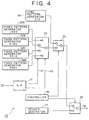
- Fig. 4 is a block diagram showing the details of the 4-1 modulator 28.
- a serial-parallel converter 31 in the 4-1 modulator 28 receives the serial data SB, which are composed of the copyright protective information ED and the error correcting code, from the ECC circuit 27 and, after dividing the data SB in unit of 2 bits, delivers the 2-bit data (b1, b0) as its output.
- a fixed pattern generator 32A repeatedly outputs a fixed pattern of logic 1000, which corresponds to logic 00 of the data (b1, b0) described in connection with Fig. 1, in synchronism with clock pulses obtained from an unshown clock generator.
- fixed pattern generators 32B to 32D repeatedly output fixed patterns of logic 0100, 0010 and 0001 corresponding respectively to logic 01, 10 and 11 of the data (b1, b0) described in connection with Fig. 1.
- a data selector 33 delivers the output data of the fixed pattern genertors 32A to 32D selectively in accordance with the logic values of the data (b1, b0).
- a sync pattern generator 34 repeatedly outputs, in synchronism with clock pulses, a bit pattern of logic 010 corresponding to the sync pattern described in connection with Fig. 1.
- a data selector 35 selectively switches, under control of a controller 36, either the output data of the data selector 33 or the output data of the sync pattern generator 34, and then delivers the selected output data. Consequently, the 4-1 modulator 28 disposes a sync pattern per 2-bit recording of the copyright protective information ED and the error correcting code.
- a header generator 37 outputs a fixed pattern of logic 010001000100 corresponding to the header described in connection with Fig. 1.
- a data selector 38 selectively delivers either the output data of the header generator 37 or the output data of the data selector 35, whereby a modulated signal PM is so produced as to dispose a header at the top of the copyright protective information ED.
- the controller 36 is a circuit for controlling the entire operation of the 4-1 modulator 28, and controls the operations of the data selectors 35 and 38 in such a manner as to dispose the header, copyright protective information ED, error correcting code and sync pattern as described in connection with Fig. 1.
- Fig. 5 is a block diagram of an optical disk apparatus for recording and reproducing the mini disk 2 manufactured as mentioned above.
- a spindle motor 42 drives the mini disk 2 at a predetermined rotation speed under control of a servo circuit 43.
- An optical pickup 44 is held by a predetermined sled mechanism in a manner to be movable in the radial direction of the mini disk 2.
- the optical pickup 44 irradiates a laser beam onto the mini disk 2 and, after receiving the return light therefrom, outputs the result of the received light.
- the optical pickup 44 applies a modulating magnetic field while intermittently raising the light quantity of the laser beam over the light quantity in a reproduction mode, hence recording various information thermomagnetically by a so-called pulse train method.
- a matrix amplifier (MA) 45 processes the output signal of the optical pickup 44 to produce a wobble signal changed in level with meandering of grooves, a tracking error signal TK changed in level with the amount of a tracking error, a focus error signal FS changed in level with the amount of a focus error, a reproduced signal MO changed in level with the polarization plane of the return light from the mini disk 2 through utilization of the magnetic Kerr effect, and a reproduced signal HF changed in level with change of the recording film on the mini disk 2 and also with pit rows.
- the servo circuit 43 executes tracking control and focus control of the optical pickup 44 by the use of such tracking error signal TK and focus error signal FS.
- the servo circuit 43 also controls the rotation speed of the spindle motor 42 in a manner that clock pulses generated from the wobble signal have a predetermined frequency. Further the servo circuit 43 acquires address information out of the wobble signal and seeks the optical pickup 44 to a predetermined position under control of a central processing unit (CPU) 46.
- CPU central processing unit
- a low pass filter (LPF) 47 limits the pass band of the reproduced signal HF to thereby suppress any variation derived from noise of the reproduced signal HF and output the reproduced signal HF.
- An analog-to-digital (AD) converter 48 converts the analog reproduced signal HF, which is outputted from the low pass filter 47, into a digital signal in accordance with predetermined sampling clock pulses, and then outputs an 8-bit digital reproduced signal DX.
- a second decoder 49 processes the digital reproduced signal DX to thereby reproduce the data SB composed of the copyright protective information ED and the error correction code.
- An error correcting circuit (ECC) 50 executes error correction of the output data SB obtained from the second decoder 49, and then outputs the copyright protective information ED.
- the CPU 46 constitutes a control circuit for controlling the operation of the optical disk apparatus 41.
- the CPU 46 seeks the optical pickup 44 to the lead-in area under control of the servo circuit 43 as in an ordinary mini disk apparatus, thereby acquiring TOC data necessary to access the mini disk 2.
- the CPU 46 seeks the optical pickup 44 to the area ARED where the copyright protective information ED is recorded, thereby acquiring the copyright protective information ED from the error correcting circuit 50.
- the CPU 46 instructs the servo circuit 43 to execute access with the focus control alone while stopping the tracking control action, since the tracking control is difficult in the area ARED where the copyright protective information ED is recorded like a bar code.
- the CPU 46 instructs the recording/reproducing section to perform encryption by the copyright protective information ED thus acquired, hence controlling the access to the mini disk 2 to consequently achieve effective protection of the copyrighter's profit.
- a decoder 51 reproduces the clock signal by processing the reproduced signal MO, then executes eight-to-fourteen demodulation of the reproduced signal MO with reference to the clock signal, and outputs the reproduced data.
- a decryptor 52 decrypts and outputs the reproduced data with reference to the copyright protective information ED, and an error correcting circuit (ECC) 53 executes error correction of the output data obtained from the decryptor 52.
- ECC error correcting circuit
- Such error is derived from some defect or the like on the mini disk 2.
- the audio data and so forth are reproduced through encryption unique to the mini disk 2 on the basis of the copyright protective information ED.
- an error correcting circuit (ECC) 55 attaches an error correcting code to the input data received successively, and then delivers the output data.
- An encryptor 56 in the next stage encrypts the output data from the error correcting circuit 55 with reference to the copyright protective information ED, and a modulator 57 executes eight-to-fourteen modulation (EFM) of the output data from the encryptor 56 to thereby produce a modulated signal.
- EFM eight-to-fourteen modulation
- This modulated signal serves to drive the modulation coil of the optical pickup 44.
- the optical disk apparatus 41 records the audio data and so forth through encryption unique to the mini disk 2 on the basis of the copyright protective information ED.
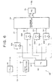
- Fig. 6 is a block diagram of the second decoder 49.
- a PLL circuit 60 reproduces a channel clock signal CK from the digital reproduced signal DX.
- a sync detector 61 decides the level of the digital reproduced signal DX with reference to the channel clock signal CK, thereby detecting a sync pattern and outputting a reset pulse SY.
- a timing generator 62 produces, on the basis of such a reset pulse SY, sampling pulses T1 to T4 of which signal levels rise at a timing corresponding substantially to the center of each of the first to fourth minute sub-areas that follow the sync pattern described in connection with Fig. 1.
- Flip-flop circuits (FF) 63A to 63D latch the digital reproduced signal DX with reference to the sampling pulses T1 to T4 respectively, so that the second decoder 49 enables the flip-flop circuits 63A to 63D to latch and hold the levels of the reproduced signals obtained respectively from the four minute sub-areas assigned to two bits of the copyright protective information ED and the error correcting code.
- a maximum detector 64 decodes the 2-bit data (b1, b0) of the copyright protective information ED and the error correcting code in accordance with the decided values of such four latched results D1 to D4. And a parallel-serial converter (PS) converts the parallel 2-bit data (b1, b0), which are outputted successively from the maximum detector 64, into serial data.
- PS parallel-serial converter
- the copyright protective information ED is decoded in accordance with the decided signal level values of the reproduced signals obtained with regard to the four minute sub-areas assigned for recording the copyright protective information ED, and even in case some signal level change at low frequencies is contained in the reproduced signal, it is still possible to achieve exact reproduction of the copyright protective information ED with certainty.
- the copyright protective information ED may be decoded by executing binary discrimination of the reproduced signal and detecting the timing of rise of the binary discrimination result to logic 1 or the timing of fall thereof to logic 0.
- the reproduced signal on the optical disk includes some low-frequency signal level change, and in case the four minute sub-areas extend over a long distance in the radial direction of the mini disk 2 as in this embodiment, there is possibility that such low-frequency signal level change may harmfully affect the decode result.
- the copyright protective information ED is decoded by sampling the signal levels corresponding to the individual areas, and then comparing the sampling results mutually, whereby the copyright protective information ED can be decoded with certainty.
- the pass band is limited in advance through the low pass filter 47 so as not to cause any error that may otherwise be induced by some noise in the numerical decision of the signal level value.
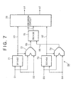
- Fig. 7 is a block diagram of the maximum detector 64 which executes such numerical decision of the signal level value.
- a digital comparator 71 numerically decides the level value in response to the latch results D1 and D2 which, out of the entire four latch results D1 to D4, correspond to the two minute sub-areas near the sync pattern.
- the digital comparator 71 raises the logic value of the comparison result H1 if the latch result D1 near the sync pattern has a greater value out of the two latch results D1 and D2.
- a data selector 72 selectively outputs the latch result of a greater value out of the latch results D1 and D2 inputted to the digital comparator 71.
- the latch result D1 near the sync pattern is outputted.
- the latch result D2 distant from the sync pattern is outputted.
- a digital comparator 73 numerically decides the level value in response to the latch results D3 and D4 which, out of the entire four latch results D1 to D4, correspond to the two minute sub-areas distant from the sync pattern.
- the digital comparator 73 raises the logic value of the comparison result H2 in case the latch result D3 near the sync pattern out of the two latch results D3 and D4 has a greater value.
- a data selector 74 selectively outputs the latch result of a greater value out of the latch results D3 and D4 inputted to the digital comparator 73.
- the latch result D3 near the sync pattern is outputted.
- the latch result D4 distant from the sync pattern is outputted.
- a digital comparator 75 numerically decides the level value in response to the output data of the data selectors 72 and 74.
- the digital comparator 75 raises the logic value of the comparison result H3 in case the output data of the data selector 72, which corresponds to the latch result near the sync pattern, has a greater value in the output data of the data selectors 72 and 74.
- a decision circuit 76 decodes the 2-bit data (b1, b0) from the detection result and then delivers its decoded output. More specifically, when the third comparison result H3 is logic 1, the maximum latch result D1 or D2 is indicated by the first comparison result H1. Therefore, in case the first comparison result H1 is logic 1, the circuit 76 judges that a pattern of logic 1000 is assigned to the four minute sub-areas, and delivers the output data (b1, b0) of logic 00. In case the first comparison result H1 is logic 0, the circuit 76 judges that a pattern of logic 0100 is assigned to the four minute sub-areas, and delivers the output data (b1, b0) of logic 01.
- the circuit 76 judges that a pattern of logic 0010 is assigned to the four minute sub-areas, and delivers the output data (b1, b0) of logic 10. And in case the second comparison result H2 is logic 0, the circuit 76 judges that a pattern of logic 0001 is assigned to the four minute sub-areas, and delivers the output data (b1, b0) of logic 11.
- Such relationship mentioned above can be expressed as follows.
- the mini disk 2 (Fig. 2) is manufactured by first exposing a disk master 8 by means of a cutting machine 7, then producing a mother disk 12 through execution of a development step 9 and a plating step 10, and mass-producing disk substrates 14 by the use of a stamper made from the mother disk 12. Further a magneto-optical recording film and a protective film are formed on each disk substrate 14 and, after copyright protective information ED is recorded like a bar code by the bar code writer 18, the disk substrate 14 is shipped.
- the mini disk 2 (Fig. 3) is so processed that an error correcting code is attached by the ECC circuit 27 to the copyright protective information ED outputted from the signal source 16, then a predetermined modulated signal PM is generated by the 4-1 modulator 28, and a laser beam L1 emitted from the laser beam source 24 is irradiated after being raised intermittently in accordance with the modulated signal PM. Consequently, on the mini disk 2, the copyright protective information ED is recorded as local and unreversible changes of the information recording film in a predetermined inner area ARED by unreversible changes of the reflective film or by partial removal of the reflective film.
- the copyright protective information is recorded on the mini disk 2 by repetition of the local regions which cause, as compared with pits or marks, greater changes on the result of the received light in the reproducing mode.
- the objective lens 26 for condensing the laser beam L1 consists of a cylindrical lens, the laser beam L1 is irradiated in a radially narrow and long shape, whereby the copyright protective information ED is recorded like a bar code.
- the area ARED for recording the copyright protective information ED is divided substantially at a pitch of 50 ⁇ m in the circumferential direction to thereby define minute sub-areas. And with regard to three of entire 12 continuous minute sub-areas, local changes of the information recording plane are formed in the header by a pattern which is not generated in recording the succeeding copyright protective information ED and error correcting code.
- continuous minute sub-areas posterior to the header are divided in unit of seven, and two bits of a sync pattern, the copyright protective information ED or the error correcting code are recorded in seven minute sub-areas. That is, local changes are formed to record a sync pattern with regard to the center one of the three minute sub-areas at the beginning of the seven continuous minute sub-areas. And one of the remaining four minute sub-areas is selected in accordance with the copyright protective information ED or the error correcting code, and local changes are formed in the selected minute sub-area to thereby record two bits of the copyright protective information ED or the error correcting code.
- the copyright protective information ED is so recorded that the regions with local changes formed therein are existent at a ratio of 0.285 which is smaller than 0.3 of the whole. And even in case the copyright protective information ED is recorded by repetition of the local regions which cause greater changes in the light receiving result as compared with pits or marks, it is possible to reproduce the copyright protective information with certainty under exact focus control. And due to disposition of a sync pattern of three minute sub-areas for every four continuous minute sub-areas, the copyright protective information ED can be reproduced with certainty despite occurrence of any rotational variation or the like.
- the conventional bar code recording data to be recorded are processed through PE modulation to generate a modulated signal, and a laser beam is irradiated in accordance with such modulated signal, so that local changes formed in the circumferential direction of an optical disk are eventually existent at a ratio of 0.5.
- the existence ratio is 0.285 which is smaller than 0.3, hence reducing the rate of time periods during which the return light of a sufficient quantity fails to be detected. Accordingly, any harmful influence on the focus servo and so forth can be decreased correspondingly to such reduction, thereby realizing satisfactory recording of the copyright protective information on the mini disk 2. Consequently, it becomes possible in the reproducing mode to achieve a stable operation of the focus servo and so forth, and design of the focus servo and the like in the reproducing apparatus can be further simplified in structure.
- the mini disk 2 shipped after such recording of the copyright protective information ED is loaded in the optical disk apparatus 41 (Fig. 5), wherein a reproduced signal HF representing the return-light receiving result obtained by irradiation of a laser beam is converted into a digital reproduced signal DX by the analog-to-digital converter 48 and then is processed in the second decoder 49, hence reproducing the copyright protective information ED. And further the audio data and so forth are encrypted and recorded in accordance with the reproduced copyright protective information ED, or the reproduced audio data and so forth are decrypted in accordance therewith.
- the encrypted data can be decrypted properly on the mini disk 2 where the copyright protective information ED is recorded legally, thereby enabling the user to enjoy, without any hindrance, the music performance recorded on the mini disk 2.
- the encrypted data fail to be decrypted properly, so that it is difficult for the user to enjoy the music recorded on the mini disk 2, hence devaluating the pirate disk.
- the mini disk 2 it becomes possible to prevent diffusion of pirate disks to eventually protect the copyrighter's profit.
- the data are encrypted in accordance with the copyright protective information ED to thereby prevent illegal copying of the data onto any pirate disk or the like.
- a sync pattern is detected by the sync detector 61, and then the digital reproduced signal DX is sampled sequentially by the flip-flop circuits 63A to 63D in response to sampling pulses T1 to T4 based on the detection of the sync pattern, whereby the level of the reproduced signal HF is detected with regard to each of the four minute sub-areas assigned to recording of the copyright protective information ED and the error correcting code.
- the maximum detector 64 Fig.
- the four sampling results thus obtained are compared successively, then a decision is made as to which of the four minute sub-areas is assigned to the regions with local changes, and the copyright protective information ED and the error correcting code are decoded successively in accordance with the result of such decision.
- the existence ratio of such local regions in the circumferential direction is set to be less than 0.3, so that even in the case of recording the information of copyright like a bar code for example, any abnormal function of the focus servo and so forth can be effectively avoided to ensure exact reproduction of the copyright protective information ED.
- a sync pattern is disposed in recording four continuous minute sub-areas in unit of two bits, whereby the copyright protective information ED can be reproduced with certainty despite occurrence of any rotational variations or the like.
- the information of copyright recorded on the mini disk is reproduced by comparing the sampling results which are obtained by sampling the light receiving results at predetermined timings, hence effectively avoiding erroneous decoding that may be induced by DC level variations as in decoding the copyright protective information ED through mere binary discrimination. Consequently, even in the case of recording the copyright protective information ED like a bar code at a relatively low transmission rate, it is still possible to achieve exact reproduction of the copyright protective information ED.
- one minute sub-area there is described a case of changing one minute sub-area entirely.
- the present invention is not limited to this example alone, and one minute sub-area may be changed partially so as to further reduce the influence on the focus servo and so forth.
- the present invention is not limited thereto alone, and the copyright protective information ED may be recorded like a bar code by, for example, locally coarsening the surface of the disk substrate 14 or locally removing some pit rows to thereby change the information recording plane optically.
- the present invention is not limited to this example alone, and it is possible to use a carbonic acid gas (CO 2 ) laser, a high-output semiconductor laser or the like.
- CO 2 carbonic acid gas
- the copyright protective information ED can be reproduced with certainty by detecting the minimum value instead of the maximum value in the maximum detector, or by inserting an inverting amplifier in the reproduced signal processor.
- the present invention is not limited to this example alone, and it is applicable also to a magneto-optical disk or a phase change type optical disk similarly adapted for both recording and reproduction, and further to a write-once type optical disk or a reproduction-only optical disk as well.
- the present invention is not limited to this example alone, and it is widely applicable to control of access to an optical disk by stopping, under control, the operation of a recording/reproducing section, or to control of access to an optical disk by stopping the output of the reproduced signal.
- copyright information may be composed of specific information unique to the relevant artist for example.
- the existence ratio of such local regions in the circumferential direction is set to be less than 0.3. Therefore, even in case the copyright information is recorded like a bar code for example, the information can be reproduced exactly with certainty.
Priority Applications (1)
| Application Number | Priority Date | Filing Date | Title |
|---|---|---|---|
| EP10174696A EP2251866B1 (fr) | 2000-06-07 | 2001-06-07 | Appareil de disque optique, procédé d'enregistrement d'un disque optique, et disque optique |
Applications Claiming Priority (2)
| Application Number | Priority Date | Filing Date | Title |
|---|---|---|---|
| JP2000175574A JP4395998B2 (ja) | 2000-06-07 | 2000-06-07 | 光ディスク装置、光ディスクの記録方法及び光ディスク |
| JP2000175574 | 2000-06-07 |
Publications (3)
| Publication Number | Publication Date |
|---|---|
| EP1162615A2 true EP1162615A2 (fr) | 2001-12-12 |
| EP1162615A3 EP1162615A3 (fr) | 2004-05-19 |
| EP1162615B1 EP1162615B1 (fr) | 2010-09-01 |
Family
ID=18677433
Family Applications (2)
| Application Number | Title | Priority Date | Filing Date |
|---|---|---|---|
| EP10174696A Expired - Lifetime EP2251866B1 (fr) | 2000-06-07 | 2001-06-07 | Appareil de disque optique, procédé d'enregistrement d'un disque optique, et disque optique |
| EP01113898A Expired - Lifetime EP1162615B1 (fr) | 2000-06-07 | 2001-06-07 | Appareil de disque optique, procédé d'enregistrement d'un disque optique, et disque optique |
Family Applications Before (1)
| Application Number | Title | Priority Date | Filing Date |
|---|---|---|---|
| EP10174696A Expired - Lifetime EP2251866B1 (fr) | 2000-06-07 | 2001-06-07 | Appareil de disque optique, procédé d'enregistrement d'un disque optique, et disque optique |
Country Status (6)
| Country | Link |
|---|---|
| US (1) | US6775215B2 (fr) |
| EP (2) | EP2251866B1 (fr) |
| JP (1) | JP4395998B2 (fr) |
| CN (1) | CN100433138C (fr) |
| DE (1) | DE60142944D1 (fr) |
| HK (1) | HK1046764A1 (fr) |
Cited By (3)
| Publication number | Priority date | Publication date | Assignee | Title |
|---|---|---|---|---|
| EP1529285A1 (fr) * | 2002-08-17 | 2005-05-11 | Lg Electronics Inc. | Disque optique lecture seule de haute densite, procede d'enregistrement d'informations de disque (di) sur ce disque optique lecture seule de haute densite et procede de reproduction de donnees enregistrees sur ce disque optique lecture seule de haute densite |
| WO2006102856A1 (fr) * | 2005-03-30 | 2006-10-05 | Zdenek Varga | Protection de disque de stockage de donnees contre la copie illegale |
| EP2109107A1 (fr) * | 2000-09-21 | 2009-10-14 | Sony Corporation | Support d'enregistrement semblable à un disque, appareil d'enregistrement de disque et procédé d'enregistrement de disque, et appareil de lecture de disque et procédé de lecture de disque |
Families Citing this family (13)
| Publication number | Priority date | Publication date | Assignee | Title |
|---|---|---|---|---|
| JP4300705B2 (ja) * | 2000-12-05 | 2009-07-22 | ソニー株式会社 | データ転送システム、データ転送装置、データ転送方法、記録媒体 |
| TWI254292B (en) | 2002-01-25 | 2006-05-01 | Sony Corp | Information recording device and method, information reproducing device and method, recording medium and disc recording medium |
| TWI258135B (en) | 2002-01-25 | 2006-07-11 | Sony Corp | Information recording device and method, information reproducing device and method, recording medium, and disc recording medium |
| US7016294B2 (en) * | 2002-03-25 | 2006-03-21 | Dphi Acquisitions, Inc. | Inner region identifier for optical disk |
| CN101241743B (zh) * | 2003-02-25 | 2012-12-12 | Lg电子株式会社 | 光学记录媒体的缺陷管理方法及装置 |
| US20040172548A1 (en) * | 2003-03-01 | 2004-09-02 | Anderson Daryl E. | Access permission based on optically readable marking on optical disc label region |
| JP4139801B2 (ja) * | 2003-09-11 | 2008-08-27 | シャープ株式会社 | 情報記録媒体再生装置、及び情報記録媒体再生方法 |
| CN101656093B (zh) * | 2003-11-10 | 2013-02-27 | 松下电器产业株式会社 | 播放装置及播放方法 |
| US7565062B2 (en) | 2003-11-10 | 2009-07-21 | Panasonic Corporation | Recording medium, reproduction device, program, reproduction method, and system integrated circuit |
| US7570555B2 (en) * | 2004-01-09 | 2009-08-04 | Panasonic Corporation | Digital data demodulator |
| JP2009181658A (ja) * | 2008-01-31 | 2009-08-13 | Toshiba Corp | 再生装置および再生装置における再生方法 |
| KR100947264B1 (ko) * | 2009-07-10 | 2010-03-11 | 주식회사 엘에스텍 | 레이저를 이용한 패턴형성장치 |
| US9459955B2 (en) * | 2012-05-24 | 2016-10-04 | Sandisk Technologies Llc | System and method to scramble data based on a scramble key |
Citations (4)
| Publication number | Priority date | Publication date | Assignee | Title |
|---|---|---|---|---|
| EP0741382A1 (fr) * | 1994-11-17 | 1996-11-06 | Matsushita Electric Industrial Co., Ltd. | Appareil generateur de marquage, procede de formation d'un marquage au laser sur disque optique, appareil de reproduction, disque optique et procede de production de disque optique |
| EP0807929A1 (fr) * | 1995-10-09 | 1997-11-19 | Matsushita Electric Industrial Co., Ltd. | Disque optique; procede de formation de codes barres pour disque optique; appareil de reproduction de disque optique, et procede de marquage; procede de marquage au laser pour disque optique, et procede de fabrication de disque optique |
| JPH10269577A (ja) * | 1997-03-21 | 1998-10-09 | Sony Corp | 光情報記録装置、光情報再生装置及び光情報記録媒体 |
| EP1005023A1 (fr) * | 1995-10-09 | 2000-05-31 | Matsushita Electric Industrial Co., Ltd. | Appareil de reproduction pour la reproduction de l'information cryptée |
Family Cites Families (9)
| Publication number | Priority date | Publication date | Assignee | Title |
|---|---|---|---|---|
| US4606016A (en) * | 1984-02-08 | 1986-08-12 | Optical Storage International | Write protection and data detection using differential detector |
| JPH10106146A (ja) * | 1996-09-25 | 1998-04-24 | Victor Co Of Japan Ltd | ディスクの記録再生方法及び再生装置 |
| KR100215705B1 (ko) * | 1996-11-02 | 1999-08-16 | 구자홍 | 기기록 정보의 보호기능을 가진 정보 기록방법 |
| JP3209126B2 (ja) * | 1996-12-20 | 2001-09-17 | 日本ビクター株式会社 | 光記録媒体及び光ディスク再生装置並びに光ディスク再生方法 |
| JP3753205B2 (ja) * | 1997-07-04 | 2006-03-08 | 日本ビクター株式会社 | 光ディスク及びその再生装置 |
| KR100601598B1 (ko) * | 1998-06-15 | 2006-07-14 | 삼성전자주식회사 | 기록 방지 정보를 저장하는 기록 매체와 기록 방지 방법 |
| EP1054395B1 (fr) * | 1999-05-17 | 2007-06-27 | Sony Corporation | Appareil d'enregistrement de disque optique, méthodes d'enregistrement de disque optique, et disques optiques |
| KR100365353B1 (ko) * | 2000-04-11 | 2002-12-18 | 엘지전자 주식회사 | 복사 방지 수단이 마련된 컴팩트 디스크 재생/기록기 및그 복사방법 |
| JP4310890B2 (ja) * | 2000-06-01 | 2009-08-12 | ソニー株式会社 | 光ディスク装置、光ディスクのアクセス方法及び光ディスク |
-
2000
- 2000-06-07 JP JP2000175574A patent/JP4395998B2/ja not_active Expired - Lifetime
-
2001
- 2001-06-06 US US09/874,280 patent/US6775215B2/en not_active Expired - Fee Related
- 2001-06-07 DE DE60142944T patent/DE60142944D1/de not_active Expired - Lifetime
- 2001-06-07 CN CNB011232773A patent/CN100433138C/zh not_active Expired - Lifetime
- 2001-06-07 EP EP10174696A patent/EP2251866B1/fr not_active Expired - Lifetime
- 2001-06-07 EP EP01113898A patent/EP1162615B1/fr not_active Expired - Lifetime
-
2002
- 2002-09-05 HK HK02106557.0A patent/HK1046764A1/xx not_active IP Right Cessation
Patent Citations (5)
| Publication number | Priority date | Publication date | Assignee | Title |
|---|---|---|---|---|
| EP0741382A1 (fr) * | 1994-11-17 | 1996-11-06 | Matsushita Electric Industrial Co., Ltd. | Appareil generateur de marquage, procede de formation d'un marquage au laser sur disque optique, appareil de reproduction, disque optique et procede de production de disque optique |
| EP0807929A1 (fr) * | 1995-10-09 | 1997-11-19 | Matsushita Electric Industrial Co., Ltd. | Disque optique; procede de formation de codes barres pour disque optique; appareil de reproduction de disque optique, et procede de marquage; procede de marquage au laser pour disque optique, et procede de fabrication de disque optique |
| EP1003162A1 (fr) * | 1995-10-09 | 2000-05-24 | Matsushita Electric Industrial Co., Ltd. | Disque optique et appareil de reproduction optique |
| EP1005023A1 (fr) * | 1995-10-09 | 2000-05-31 | Matsushita Electric Industrial Co., Ltd. | Appareil de reproduction pour la reproduction de l'information cryptée |
| JPH10269577A (ja) * | 1997-03-21 | 1998-10-09 | Sony Corp | 光情報記録装置、光情報再生装置及び光情報記録媒体 |
Non-Patent Citations (1)
| Title |
|---|
| PATENT ABSTRACTS OF JAPAN vol. 1999, no. 01, 29 January 1999 (1999-01-29) -& JP 10 269577 A (SONY CORP), 9 October 1998 (1998-10-09) & US 6 078 552 A (YAMAMOTO MASANOBU ET AL) 20 June 2000 (2000-06-20) * |
Cited By (6)
| Publication number | Priority date | Publication date | Assignee | Title |
|---|---|---|---|---|
| EP2109107A1 (fr) * | 2000-09-21 | 2009-10-14 | Sony Corporation | Support d'enregistrement semblable à un disque, appareil d'enregistrement de disque et procédé d'enregistrement de disque, et appareil de lecture de disque et procédé de lecture de disque |
| EP2112662A1 (fr) * | 2000-09-21 | 2009-10-28 | Sony Corporation | Support d'enregistrement en forme de disque, appareil et méthode d'enregistrement de disque, appareil et méthode de reproduction de disque |
| US7760610B2 (en) | 2000-09-21 | 2010-07-20 | Sony Corporation | Recording medium including first and second areas, the second area including a written multiply block, and recording and reproducing methods and apparatus thereof |
| EP1529285A1 (fr) * | 2002-08-17 | 2005-05-11 | Lg Electronics Inc. | Disque optique lecture seule de haute densite, procede d'enregistrement d'informations de disque (di) sur ce disque optique lecture seule de haute densite et procede de reproduction de donnees enregistrees sur ce disque optique lecture seule de haute densite |
| EP1529285A4 (fr) * | 2002-08-17 | 2005-11-02 | Lg Electronics Inc | Disque optique lecture seule de haute densite, procede d'enregistrement d'informations de disque (di) sur ce disque optique lecture seule de haute densite et procede de reproduction de donnees enregistrees sur ce disque optique lecture seule de haute densite |
| WO2006102856A1 (fr) * | 2005-03-30 | 2006-10-05 | Zdenek Varga | Protection de disque de stockage de donnees contre la copie illegale |
Also Published As
| Publication number | Publication date |
|---|---|
| CN100433138C (zh) | 2008-11-12 |
| JP2001351243A (ja) | 2001-12-21 |
| EP1162615B1 (fr) | 2010-09-01 |
| HK1046764A1 (en) | 2003-01-24 |
| US20020024904A1 (en) | 2002-02-28 |
| JP4395998B2 (ja) | 2010-01-13 |
| EP1162615A3 (fr) | 2004-05-19 |
| EP2251866B1 (fr) | 2012-02-15 |
| US6775215B2 (en) | 2004-08-10 |
| DE60142944D1 (de) | 2010-10-14 |
| CN1338731A (zh) | 2002-03-06 |
| EP2251866A3 (fr) | 2011-01-19 |
| EP2251866A2 (fr) | 2010-11-17 |
Similar Documents
| Publication | Publication Date | Title |
|---|---|---|
| US6987715B2 (en) | Apparatus and associated methodology of imparting content protection to optically recorded data for secure reproduction | |
| US6775215B2 (en) | Optical disk apparatus, optical disk recording method, and optical disk | |
| JP2000195049A (ja) | 光ディスク記録装置、光ディスクの記録方法、光ディスク再生装置、光ディスクの再生方法及び光ディスク | |
| JP3551727B2 (ja) | 光情報記録装置、光情報記録媒体及び光情報再生装置 | |
| JPWO2003003358A1 (ja) | データの記録媒体、記録媒体の記録及び/又は再生装置並びに記録又は再生方法 | |
| JP4310885B2 (ja) | 光ディスク装置、光ディスクのアクセス方法及び光ディスク | |
| JP4449175B2 (ja) | 光ディスク装置、光ディスクの記録方法、光ディスク、光ディスクの再生方法 | |
| JPH11126425A (ja) | 光ディスク装置、光ディスクの再生方法及び光ディスク | |
| JP4442692B2 (ja) | 光ディスク装置、光ディスクの記録方法、光ディスク、光ディスクの再生方法、光ディスクの再生装置、処理装置および変調装置 |
Legal Events
| Date | Code | Title | Description |
|---|---|---|---|
| PUAI | Public reference made under article 153(3) epc to a published international application that has entered the european phase |
Free format text: ORIGINAL CODE: 0009012 |
|
| AK | Designated contracting states |
Kind code of ref document: A2 Designated state(s): AT BE CH CY DE DK ES FI FR GB GR IE IT LI LU MC NL PT SE TR |
|
| AX | Request for extension of the european patent |
Free format text: AL;LT;LV;MK;RO;SI |
|
| PUAL | Search report despatched |
Free format text: ORIGINAL CODE: 0009013 |
|
| AK | Designated contracting states |
Kind code of ref document: A3 Designated state(s): AT BE CH CY DE DK ES FI FR GB GR IE IT LI LU MC NL PT SE TR |
|
| AX | Request for extension of the european patent |
Extension state: AL LT LV MK RO SI |
|
| 17P | Request for examination filed |
Effective date: 20040914 |
|
| AKX | Designation fees paid |
Designated state(s): DE FR GB NL |
|
| 17Q | First examination report despatched |
Effective date: 20070716 |
|
| GRAP | Despatch of communication of intention to grant a patent |
Free format text: ORIGINAL CODE: EPIDOSNIGR1 |
|
| GRAS | Grant fee paid |
Free format text: ORIGINAL CODE: EPIDOSNIGR3 |
|
| GRAA | (expected) grant |
Free format text: ORIGINAL CODE: 0009210 |
|
| AK | Designated contracting states |
Kind code of ref document: B1 Designated state(s): DE FR GB NL |
|
| REG | Reference to a national code |
Ref country code: GB Ref legal event code: FG4D |
|
| REF | Corresponds to: |
Ref document number: 60142944 Country of ref document: DE Date of ref document: 20101014 Kind code of ref document: P |
|
| REG | Reference to a national code |
Ref country code: NL Ref legal event code: T3 |
|
| PLBE | No opposition filed within time limit |
Free format text: ORIGINAL CODE: 0009261 |
|
| STAA | Information on the status of an ep patent application or granted ep patent |
Free format text: STATUS: NO OPPOSITION FILED WITHIN TIME LIMIT |
|
| 26N | No opposition filed |
Effective date: 20110606 |
|
| REG | Reference to a national code |
Ref country code: DE Ref legal event code: R097 Ref document number: 60142944 Country of ref document: DE Effective date: 20110606 |
|
| REG | Reference to a national code |
Ref country code: DE Ref legal event code: R084 Ref document number: 60142944 Country of ref document: DE |
|
| REG | Reference to a national code |
Ref country code: GB Ref legal event code: 746 Effective date: 20150424 |
|
| REG | Reference to a national code |
Ref country code: DE Ref legal event code: R084 Ref document number: 60142944 Country of ref document: DE Effective date: 20150410 |
|
| REG | Reference to a national code |
Ref country code: FR Ref legal event code: PLFP Year of fee payment: 16 |
|
| REG | Reference to a national code |
Ref country code: FR Ref legal event code: PLFP Year of fee payment: 17 |
|
| REG | Reference to a national code |
Ref country code: FR Ref legal event code: PLFP Year of fee payment: 18 |
|
| PGFP | Annual fee paid to national office [announced via postgrant information from national office to epo] |
Ref country code: DE Payment date: 20180625 Year of fee payment: 18 Ref country code: NL Payment date: 20180620 Year of fee payment: 18 |
|
| PGFP | Annual fee paid to national office [announced via postgrant information from national office to epo] |
Ref country code: FR Payment date: 20180620 Year of fee payment: 18 |
|
| PGFP | Annual fee paid to national office [announced via postgrant information from national office to epo] |
Ref country code: GB Payment date: 20180620 Year of fee payment: 18 |
|
| REG | Reference to a national code |
Ref country code: DE Ref legal event code: R119 Ref document number: 60142944 Country of ref document: DE |
|
| REG | Reference to a national code |
Ref country code: NL Ref legal event code: MM Effective date: 20190701 |
|
| GBPC | Gb: european patent ceased through non-payment of renewal fee |
Effective date: 20190607 |
|
| PG25 | Lapsed in a contracting state [announced via postgrant information from national office to epo] |
Ref country code: NL Free format text: LAPSE BECAUSE OF NON-PAYMENT OF DUE FEES Effective date: 20190701 Ref country code: DE Free format text: LAPSE BECAUSE OF NON-PAYMENT OF DUE FEES Effective date: 20200101 Ref country code: GB Free format text: LAPSE BECAUSE OF NON-PAYMENT OF DUE FEES Effective date: 20190607 |
|
| PG25 | Lapsed in a contracting state [announced via postgrant information from national office to epo] |
Ref country code: FR Free format text: LAPSE BECAUSE OF NON-PAYMENT OF DUE FEES Effective date: 20190630 |