EP1162319A2 - Cistern to be built-in into the wall - Google Patents
Cistern to be built-in into the wall Download PDFInfo
- Publication number
- EP1162319A2 EP1162319A2 EP01113773A EP01113773A EP1162319A2 EP 1162319 A2 EP1162319 A2 EP 1162319A2 EP 01113773 A EP01113773 A EP 01113773A EP 01113773 A EP01113773 A EP 01113773A EP 1162319 A2 EP1162319 A2 EP 1162319A2
- Authority
- EP
- European Patent Office
- Prior art keywords
- wall
- cistern
- box body
- inspection
- opening
- Prior art date
- Legal status (The legal status is an assumption and is not a legal conclusion. Google has not performed a legal analysis and makes no representation as to the accuracy of the status listed.)
- Granted
Links
Images


Classifications
-
- E—FIXED CONSTRUCTIONS
- E03—WATER SUPPLY; SEWERAGE
- E03D—WATER-CLOSETS OR URINALS WITH FLUSHING DEVICES; FLUSHING VALVES THEREFOR
- E03D1/00—Water flushing devices with cisterns ; Setting up a range of flushing devices or water-closets; Combinations of several flushing devices
- E03D1/01—Shape or selection of material for flushing cisterns
- E03D1/012—Details of shape of cisterns, e.g. for connecting to wall, for supporting or connecting flushing-device actuators
- E03D1/0125—Details of shape of cisterns, e.g. for connecting to wall, for supporting or connecting flushing-device actuators of built-in cisterns
Definitions
- the invention relates to a wall-mounted cistern with a box body, in which an inspection opening is provided at least in one wall.
- Wall-mounted cisterns of this type are known and are sold with inspection openings of different sizes. The inspection opening is closed after installation in the building wall with a cover plate, an actuating device for triggering the flushing process being integrated in the cover plate. Cover plates of this type are of different sizes, for example for design reasons.
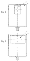
- Wall-mounted cisterns as shown in the drawing in FIG. 1 and FIG. 2, are therefore sold.
- a small inspection opening 2 is formed in a side wall of the body 1.
- the wall-mounted cistern shown in FIG. 2 differs from that shown in FIG. 1 only in that a large inspection opening 3 is formed in the side wall of the box body 1. This requires a relatively complex storage and production, since two wall-mounted cisterns must be kept ready.
- the invention has for its object to improve the known wall-mounted cistern and in particular to design it so that different inspection openings can be used in a wall-mounted cistern.
- This object is achieved with the features of claim 1 or claim 2 or claim 3.
- claim 4 a further embodiment of the invention is specified according to claim 3.
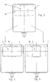
- FIGS. 3 to 5 of the drawing a box body 1 is shown, on the front of which a first inspection opening 2 is predefined with a corrugated or perforated boundary line 14 and a second inspection opening 3 with a corrugated or perforated boundary line 15.
- the required inspection opening 2, 3 can be made by breaking out or by cutting out with a knife along the corrugated or perforated boundary line 14 or 15.
- FIG. 4 shows the box body 1 shown in FIG. 3 with a large inspection opening 3 produced by cutting out on the boundary line 15, while in FIG. 5 the box body 1 is shown with a small inspection opening 2 produced by cutting out on the boundary line 14.
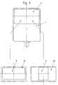
- FIG. 6 to 8 is one at the front of the box body 1 relatively large opening 11 formed.
- an adapter plate 40, 41 can be used, a smaller one in the adapter plate 40 Revision opening 2 and in the adapter plate 41 a larger inspection opening 3 is formed.
- the box body 1 is in the opening 11 the adapter plate 41 arranged in which the large Inspection opening 3 is formed.
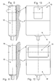
- the box body 1 is formed in two parts, an upper part 13 being able to be plugged onto a lower part 12 in a first and in a second position rotated by 180 °.
- a small inspection opening 2 is formed in the upper part 13 on a first flat side and a large inspection opening 3 is formed on a second flat side lying in parallel.
- the large inspection opening 3 (FIG. 12) can thus be arranged on the front of the box body 1.
- the exemplary embodiment described above is modified in FIGS. 13 and 14, the box body 1 being formed in one piece and, depending on the desired inspection opening 2, 3, can be fastened to the building wall 5 in the corresponding rotational position.
Abstract
Description
Die Erfindung betrifft einen Wandeinbau-Spülkasten mit
einem Kastenkörper, bei dem wenigstens in einer Wand
eine Revisionsöffnung vorgesehen ist.
Derartige Wandeinbau-Spülkästen sind bekannt und
werden mit unterschiedlich großer Revisionsöffnung
verkauft. Die Revisionsöffnung wird hierbei nach der
Installation in der Gebäudewand mit einer Abdeckplatte
verschlossen, wobei in der Abdeckplatte eine
Betätigungseinrichtung zur Auslösung des Spülvorgangs
integriert ist. Derartige Abdeckplatten werden
beispielsweise aus Designgründen unterschiedlich groß
ausgebildet. Es werden daher Wandeinbau-Spülkästen,
wie sie in der Zeichnung Figur 1 und Figur 2 gezeigt
sind, vertrieben. Bei dem in Figur 1 dargestellten
Wandeinbau-Spülkasten ist in einer Seitenwand des
Kastenkörpers 1 eine kleine Revisionsöffnung 2
ausgebildet. Der in Figur 2 dargestellte Wandeinbau-Spülkasten
unterscheidet sich zu dem in Figur 1
gezeigten lediglich dadurch, dass in der Seitenwand
des Kastenkörpers 1 eine große Revisionsöffnung 3
ausgebildet ist. Dieses erfordert eine relativ
aufwendige Lagerhaltung und Produktion, da zwei
Wandeinbau-Spülkästen bereitgehalten werden müssen.The invention relates to a wall-mounted cistern with a box body, in which an inspection opening is provided at least in one wall.
Wall-mounted cisterns of this type are known and are sold with inspection openings of different sizes. The inspection opening is closed after installation in the building wall with a cover plate, an actuating device for triggering the flushing process being integrated in the cover plate. Cover plates of this type are of different sizes, for example for design reasons. Wall-mounted cisterns, as shown in the drawing in FIG. 1 and FIG. 2, are therefore sold. In the wall-mounted cistern shown in Figure 1, a
Der Erfindung liegt die Aufgabe zugrunde, den
bekannten Wandeinbau-Spülkasten zu verbessern und
insbesondere so auszugestalten, dass unterschiedliche
Revisionsöffnungen bei einem Wandeinbau-Spülkasten zur
Anwendung gelangen können.
Diese Aufgabe wird erfindungsgemäß mit den Merkmalen,
des Anspruchs 1 oder des Anspruchs 2 oder des
Anspruchs 3 gelöst.
Im Anspruch 4 ist eine weitere erfindungsgemäße
Ausbildung nach dem Anspruch 3 angegeben.The invention has for its object to improve the known wall-mounted cistern and in particular to design it so that different inspection openings can be used in a wall-mounted cistern.
This object is achieved with the features of
In claim 4, a further embodiment of the invention is specified according to
Die mit der Erfindung erzielbaren Vorteile bestehen insbesondere darin, dass ein Wandeinbau-Spülkasten mit unterschiedlich ausgebildeten Revisionsöffnungen versehen werden kann, so dass nur ein Wandeinbau-Spülkasten für die verschiedenen Abdeckplatten benötigt wird und Einsparungen bei der Herstellung und der Lagerhaltung erzielbar sind. Darüber hinaus ermöglicht der erfindungsgemäße Wandeinbau-Spülkasten die Entscheidung, welche Abdeckplatte mit Betätigungseinrichtung verwendet werden soll, bis zur Installation auf der Baustelle zurückzustellen und kann hier optimal vom Installateur und/oder Kunden getroffen werden. The advantages that can be achieved with the invention exist in particular that a built-in cistern with differently designed inspection openings can be provided so that only a built-in cistern for the different cover plates is needed and savings in manufacturing and warehousing can be achieved. Furthermore enables the wall-mounted cistern according to the invention deciding which cover plate with Actuator to be used until Defer installation on site and can be optimally used by the installer and / or customer to be hit.
Ausführungsbeispiele der Erfindung sind in der Zeichnung in Figur 3 bis 13 dargestellt und werden im Folgenden näher beschrieben. Es zeigt
Figur 3- einen Spülkasten in Forderansicht mit zwei optional vorgegebenen Revisionsöffnungen;
- Figur 4
- den in
Figur 3 gezeigten Spülkasten mit einer großen Revisionsöffnung; Figur 5- den in
Figur 3 gezeigten Spülkasten mit einer kleinen Revisionsöffnung; - Figur 6
- ein anderes Ausführungsbeispiel eines Spülkastens in Vorderansicht mit einer relativ großen Öffnung, in die alternativ Adapterplatten mit großer oder kleiner Revisionsöffnung eingesetzt werden können;
- Figur 7
- den in Figur 6 gezeigten Spülkasten mit eingesetzter Adapterplatte mit großer Revisionsöffnung;
- Figur 8
- den in Figur 6 gezeigten Spülkasten mit eingesetzter Adapterplatte mit kleiner Revisionsöffnung;
- Figur 9
- ein weiteres Ausführungsbeispiel eines Spülkastens in zweiteiliger Form, installiert an einer Gebäudewand in Seitenansicht;
- Figur 10
- den in Figur 9 gezeigten Spülkasten in Vorderansicht mit kleiner Revisionsöffnung;
Figur 11- den in Figur 9 gezeigten Spülkasten, wobei der Oberteil um 180° zur Gebäudewand gedreht angeordnet ist;
Figur 12- den in
Figur 11 gezeigten Spülkasten in Vorderansicht mit großer Revisionsöffnung; Figur 13- ein weiteres, zu Figur 9 abgewandeltes Ausführungsbeispiel eines Spülkastens in einteiliger Form in einer ersten Drehstellung mit kleiner Revisionsöffnung;
Figur 14- den in
Figur 12 gezeigten einteiligen Spülkasten um 180° gedreht mit großer Revisionsöffnung.
- Figure 3
- a cistern in front view with two optionally specified inspection openings;
- Figure 4
- the cistern shown in Figure 3 with a large inspection opening;
- Figure 5
- the cistern shown in Figure 3 with a small inspection opening;
- Figure 6
- another embodiment of a cistern in front view with a relatively large opening into which adapter plates with a large or small inspection opening can alternatively be used;
- Figure 7
- the cistern shown in Figure 6 with an inserted adapter plate with a large inspection opening;
- Figure 8
- the cistern shown in Figure 6 with an inserted adapter plate with a small inspection opening;
- Figure 9
- another embodiment of a cistern in two parts, installed on a building wall in side view;
- Figure 10
- the cistern shown in Figure 9 in front view with a small inspection opening;
- Figure 11
- the cistern shown in Figure 9, wherein the upper part is arranged rotated by 180 ° to the building wall;
- Figure 12
- the cistern shown in Figure 11 in front view with a large inspection opening;
- Figure 13
- another embodiment of a cistern modified in FIG. 9 in one-piece form in a first rotational position with a small inspection opening;
- Figure 14
- the one-piece cistern shown in Figure 12 rotated by 180 ° with a large inspection opening.
Der Einfachheit halber sind bei den Ausführungsbeispielen
in der Zeichnung gleiche oder
entsprechende Elemente mit jeweils gleichen Bezugszeichen
versehen.
Bei dem in Figur 3 bis 5 der Zeichnung dargestellten
Ausführungsbeispiel ist ein Kastenkörper 1 gezeigt, an
dessen Vorderseite mit einer gesickten oder
perforierten Begrenzungslinie 14 eine erste
Revisionsöffnung 2 und mit einer gesickten oder
perforierten Begrenzungslinie 15 eine zweite
Revisionsöffnung 3 vorgegeben ist. Am Installationsort
auf der Baustelle kann vom Installateur eine jeweils
erforderliche Revisionsöffnung 2,3 durch Herausbrechen
oder durch ein Ausschneiden mit einem Messer entlang
der gesickten oder perforierten Begrenzungslinie 14
oder 15 hergestellt werden.
In Figur 4 ist der in Figur 3 dargestellte
Kastenkörper 1 mit einer durch Ausschneiden an der
Begrenzungslinie 15 hergestellten großen Revisionsöffnung
3 gezeigt, während in Figur 5 der Kastenkörper
1 mit einer durch Ausschneiden an der Begrenzungslinie
14 hergestellten kleinen Revisionsöffnung 2 gezeigt
ist.For the sake of simplicity, the same or corresponding elements are provided with the same reference numerals in the exemplary embodiments in the drawing.
In the exemplary embodiment shown in FIGS. 3 to 5 of the drawing, a
FIG. 4 shows the
Bei dem in Figur 6 bis 8 gezeigten Ausführungsbeispiel
ist an der Vorderseite des Kastenkörpers 1 eine
relativ große Öffnung 11 ausgebildet. In diese Öffnung
11 kann eine Adapterplatte 40,41 eingesetzt werden,
wobei in der Adapterplatte 40 eine kleinere
Revisionsöffnung 2 und in der Adapterplatte 41 eine
größere Revisionsöffnung 3 ausgebildet ist. In the embodiment shown in Figures 6 to 8
is one at the front of the
In Figur 8 ist in dem Kastenkörper 1 in der Öffnung 11
die Adapterplatte 40 eingesetzt worden, in der die
kleine Revisionsöffnung 2 ausgebildet ist.8 is in the
In Figur 7 ist in dem Kastenkörper 1 in der Öffnung 11
die Adapterplatte 41 angeordnet, in der die große
Revisionsöffnung 3 ausgebildet ist.In FIG. 7, the
Bei dem in Figur 9 bis 12 der Zeichnung dargestellten
Ausführungsbeispiel ist der Kastenkörper 1 zweiteilig
ausgebildet, wobei auf einem Unterteil 12 ein Oberteil
13 in einer ersten und in einer zweiten, um 180°
gedrehten Stellung, aufsteckbar ist. In dem Oberteil
13 ist an einer ersten Flachseite eine kleine
Revisionsöffnung 2 und an einer zweiten parallel
liegenden Flachseite eine große Revisionsöffnung 3
ausgebildet.
Bei der Installation an einer Gebäudewand 5 kann somit
entweder die kleine Revisionsöffnung 2 (Figur 10) oder
nach einer Drehung um 180° die große Revisionsöffnung
3 (Figur 12) an der Vorderseite des Kastenkörpers 1
angeordnet werden.
In den Figuren 13 und 14 ist das vorstehend
beschriebene Ausführungsbeispiel abgewandelt, wobei
der Kastenkörper 1 einstückig ausgebildet ist und je
nach der gewünschten Revisionsöffnung 2,3 in der
entsprechenden Drehstellung an der Gebäudewand 5
befestigt werden kann.In the exemplary embodiment shown in FIGS. 9 to 12 of the drawing, the
When installed on a
The exemplary embodiment described above is modified in FIGS. 13 and 14, the
Claims (4)
Applications Claiming Priority (2)
| Application Number | Priority Date | Filing Date | Title |
|---|---|---|---|
| DE10028203A DE10028203A1 (en) | 2000-06-09 | 2000-06-09 | Recessed cistern |
| DE10028203 | 2000-06-09 |
Publications (3)
| Publication Number | Publication Date |
|---|---|
| EP1162319A2 true EP1162319A2 (en) | 2001-12-12 |
| EP1162319A3 EP1162319A3 (en) | 2002-06-12 |
| EP1162319B1 EP1162319B1 (en) | 2003-04-09 |
Family
ID=7645006
Family Applications (1)
| Application Number | Title | Priority Date | Filing Date |
|---|---|---|---|
| EP01113773A Expired - Lifetime EP1162319B1 (en) | 2000-06-09 | 2001-06-06 | Cistern to be built-in into the wall |
Country Status (3)
| Country | Link |
|---|---|
| EP (1) | EP1162319B1 (en) |
| AT (1) | ATE237038T1 (en) |
| DE (2) | DE10028203A1 (en) |
Cited By (2)
| Publication number | Priority date | Publication date | Assignee | Title |
|---|---|---|---|---|
| EP1647638A2 (en) * | 2004-10-13 | 2006-04-19 | GROHEDAL Sanitärsysteme GmbH & Co.KG | Wall built-in flushing cistern |
| DE102008041413A1 (en) * | 2008-08-21 | 2010-02-25 | BSH Bosch und Siemens Hausgeräte GmbH | Laundry dryer e.g. heat pump dryer, has heating arrangement including two heat exchanger, and predetermined separation point formed in separation wall for temporary opening of maintenance opening guided by separation wall |
Citations (3)
| Publication number | Priority date | Publication date | Assignee | Title |
|---|---|---|---|---|
| DE2819684A1 (en) * | 1978-05-05 | 1979-11-08 | Keramag Keramische Werke Ag | Ceramic lavatory flush cistern - consists of square hollow monolithic unit with rear formed installation aperture |
| EP0867570A1 (en) * | 1997-03-26 | 1998-09-30 | Société dite : ALLIA Société Anonyme dont le Siège est à | Flushing cistern for recessed mounting operated at the top or at the front |
| EP0905328A1 (en) * | 1997-09-24 | 1999-03-31 | Geberit Technik Ag | Concealed flushing cistern |
-
2000
- 2000-06-09 DE DE10028203A patent/DE10028203A1/en not_active Withdrawn
-
2001
- 2001-06-06 DE DE50100151T patent/DE50100151D1/en not_active Expired - Fee Related
- 2001-06-06 AT AT01113773T patent/ATE237038T1/en not_active IP Right Cessation
- 2001-06-06 EP EP01113773A patent/EP1162319B1/en not_active Expired - Lifetime
Patent Citations (3)
| Publication number | Priority date | Publication date | Assignee | Title |
|---|---|---|---|---|
| DE2819684A1 (en) * | 1978-05-05 | 1979-11-08 | Keramag Keramische Werke Ag | Ceramic lavatory flush cistern - consists of square hollow monolithic unit with rear formed installation aperture |
| EP0867570A1 (en) * | 1997-03-26 | 1998-09-30 | Société dite : ALLIA Société Anonyme dont le Siège est à | Flushing cistern for recessed mounting operated at the top or at the front |
| EP0905328A1 (en) * | 1997-09-24 | 1999-03-31 | Geberit Technik Ag | Concealed flushing cistern |
Cited By (4)
| Publication number | Priority date | Publication date | Assignee | Title |
|---|---|---|---|---|
| EP1647638A2 (en) * | 2004-10-13 | 2006-04-19 | GROHEDAL Sanitärsysteme GmbH & Co.KG | Wall built-in flushing cistern |
| EP1647638A3 (en) * | 2004-10-13 | 2006-11-15 | GROHEDAL Sanitärsysteme GmbH & Co.KG | Wall built-in flushing cistern |
| DE102008041413A1 (en) * | 2008-08-21 | 2010-02-25 | BSH Bosch und Siemens Hausgeräte GmbH | Laundry dryer e.g. heat pump dryer, has heating arrangement including two heat exchanger, and predetermined separation point formed in separation wall for temporary opening of maintenance opening guided by separation wall |
| DE102008041413B4 (en) * | 2008-08-21 | 2013-01-03 | BSH Bosch und Siemens Hausgeräte GmbH | Clothes dryer with heat exchanger, in particular heat pump dryer, and method for opening a maintenance opening |
Also Published As
| Publication number | Publication date |
|---|---|
| EP1162319A3 (en) | 2002-06-12 |
| EP1162319B1 (en) | 2003-04-09 |
| DE50100151D1 (en) | 2003-05-15 |
| ATE237038T1 (en) | 2003-04-15 |
| DE10028203A1 (en) | 2001-12-13 |
Similar Documents
| Publication | Publication Date | Title |
|---|---|---|
| EP0319811A1 (en) | Sealing device for interlockingly maintaining a cover on a grating in a frame | |
| EP1907249B1 (en) | Support jack | |
| EP1063379A2 (en) | Hinge | |
| DE112015006906T5 (en) | Cam lock | |
| EP0708219A1 (en) | Fitting or the like, preferably hinge part, with fastening device | |
| EP1769125B1 (en) | Device for locking a cover of a manhole top, and manhole top | |
| EP1118071A1 (en) | Padlock with a lockable shackle | |
| AT404857B (en) | CYLINDLE LOCK WITH CYLINDER CORE AND CYLINDER CASE AND FLAT KEY | |
| EP1162319B1 (en) | Cistern to be built-in into the wall | |
| DE202010005089U1 (en) | Sterile containers for medical purposes | |
| WO2009074190A1 (en) | Adapter for coupling a rod, such as a locking rod of a rod-type closure, to a lever, such as an actuating lever of the rod-type closure | |
| DE102019114332A1 (en) | Lock device | |
| DE102010024037B4 (en) | Simplified change mark stamp | |
| EP1532913B1 (en) | Device for damping toilet seats and/or toilet covers | |
| EP1820927B1 (en) | Sleeve module | |
| DE3543989C2 (en) | ||
| EP3604722B1 (en) | Lock | |
| DE202018102956U1 (en) | Hinge for a toilet seat set | |
| DE202015107033U1 (en) | Ratschenschlüsssel | |
| DE69811071T2 (en) | CLOSING | |
| CH702820A2 (en) | Unhingeable joint for manhole cover i.e. grid, has straight-line section whose pushing part is pushed into tiltable part up to borehole for separating former tiltable part from another tiltable part in reversible manner | |
| DE202005019156U1 (en) | Mounting set for attachment on armature, has rod shaped actuation unit removably arranged in housing and designed such that it establishes detachable, effective connection with armature | |
| DE19954068B4 (en) | lamp | |
| DE19812178C1 (en) | Friction mounting for dental cap | |
| DE20319324U1 (en) | Adjusting nut for screwing onto a threaded section, especially for fixing a tool on a drive shaft, comprises a base body divided in the peripheral direction |
Legal Events
| Date | Code | Title | Description |
|---|---|---|---|
| PUAI | Public reference made under article 153(3) epc to a published international application that has entered the european phase |
Free format text: ORIGINAL CODE: 0009012 |
|
| AK | Designated contracting states |
Kind code of ref document: A2 Designated state(s): AT BE CH CY DE DK ES FI FR GB GR IE IT LI LU MC NL PT SE TR |
|
| AX | Request for extension of the european patent |
Free format text: AL;LT;LV;MK;RO;SI |
|
| PUAL | Search report despatched |
Free format text: ORIGINAL CODE: 0009013 |
|
| AK | Designated contracting states |
Kind code of ref document: A3 Designated state(s): AT BE CH CY DE DK ES FI FR GB GR IE IT LI LU MC NL PT SE TR |
|
| AX | Request for extension of the european patent |
Free format text: AL;LT;LV;MK;RO;SI |
|
| 17P | Request for examination filed |
Effective date: 20020807 |
|
| GRAH | Despatch of communication of intention to grant a patent |
Free format text: ORIGINAL CODE: EPIDOS IGRA |
|
| GRAH | Despatch of communication of intention to grant a patent |
Free format text: ORIGINAL CODE: EPIDOS IGRA |
|
| GRAA | (expected) grant |
Free format text: ORIGINAL CODE: 0009210 |
|
| AKX | Designation fees paid |
Designated state(s): AT BE CH CY DE DK ES FI FR GB GR IE IT LI LU MC NL PT SE TR |
|
| AK | Designated contracting states |
Designated state(s): AT BE CH CY DE DK ES FI FR GB GR IE IT LI LU MC NL PT SE TR |
|
| PG25 | Lapsed in a contracting state [announced via postgrant information from national office to epo] |
Ref country code: TR Free format text: LAPSE BECAUSE OF FAILURE TO SUBMIT A TRANSLATION OF THE DESCRIPTION OR TO PAY THE FEE WITHIN THE PRESCRIBED TIME-LIMIT Effective date: 20030409 Ref country code: NL Free format text: LAPSE BECAUSE OF FAILURE TO SUBMIT A TRANSLATION OF THE DESCRIPTION OR TO PAY THE FEE WITHIN THE PRESCRIBED TIME-LIMIT Effective date: 20030409 Ref country code: IT Free format text: LAPSE BECAUSE OF FAILURE TO SUBMIT A TRANSLATION OF THE DESCRIPTION OR TO PAY THE FEE WITHIN THE PRESCRIBED TIME-LIMIT;WARNING: LAPSES OF ITALIAN PATENTS WITH EFFECTIVE DATE BEFORE 2007 MAY HAVE OCCURRED AT ANY TIME BEFORE 2007. THE CORRECT EFFECTIVE DATE MAY BE DIFFERENT FROM THE ONE RECORDED. Effective date: 20030409 Ref country code: IE Free format text: LAPSE BECAUSE OF NON-PAYMENT OF DUE FEES Effective date: 20030409 Ref country code: GB Free format text: LAPSE BECAUSE OF FAILURE TO SUBMIT A TRANSLATION OF THE DESCRIPTION OR TO PAY THE FEE WITHIN THE PRESCRIBED TIME-LIMIT Effective date: 20030409 Ref country code: FR Free format text: LAPSE BECAUSE OF FAILURE TO SUBMIT A TRANSLATION OF THE DESCRIPTION OR TO PAY THE FEE WITHIN THE PRESCRIBED TIME-LIMIT Effective date: 20030409 Ref country code: FI Free format text: LAPSE BECAUSE OF FAILURE TO SUBMIT A TRANSLATION OF THE DESCRIPTION OR TO PAY THE FEE WITHIN THE PRESCRIBED TIME-LIMIT Effective date: 20030409 |
|
| REG | Reference to a national code |
Ref country code: GB Ref legal event code: FG4D Free format text: NOT ENGLISH |
|
| REG | Reference to a national code |
Ref country code: CH Ref legal event code: EP |
|
| REG | Reference to a national code |
Ref country code: IE Ref legal event code: FG4D Free format text: GERMAN |
|
| PG25 | Lapsed in a contracting state [announced via postgrant information from national office to epo] |
Ref country code: LU Free format text: LAPSE BECAUSE OF NON-PAYMENT OF DUE FEES Effective date: 20030606 Ref country code: CY Free format text: LAPSE BECAUSE OF FAILURE TO SUBMIT A TRANSLATION OF THE DESCRIPTION OR TO PAY THE FEE WITHIN THE PRESCRIBED TIME-LIMIT Effective date: 20030606 Ref country code: AT Free format text: LAPSE BECAUSE OF NON-PAYMENT OF DUE FEES Effective date: 20030606 |
|
| PG25 | Lapsed in a contracting state [announced via postgrant information from national office to epo] |
Ref country code: MC Free format text: LAPSE BECAUSE OF NON-PAYMENT OF DUE FEES Effective date: 20030630 |
|
| PG25 | Lapsed in a contracting state [announced via postgrant information from national office to epo] |
Ref country code: SE Free format text: LAPSE BECAUSE OF FAILURE TO SUBMIT A TRANSLATION OF THE DESCRIPTION OR TO PAY THE FEE WITHIN THE PRESCRIBED TIME-LIMIT Effective date: 20030709 Ref country code: PT Free format text: LAPSE BECAUSE OF FAILURE TO SUBMIT A TRANSLATION OF THE DESCRIPTION OR TO PAY THE FEE WITHIN THE PRESCRIBED TIME-LIMIT Effective date: 20030709 Ref country code: GR Free format text: LAPSE BECAUSE OF FAILURE TO SUBMIT A TRANSLATION OF THE DESCRIPTION OR TO PAY THE FEE WITHIN THE PRESCRIBED TIME-LIMIT Effective date: 20030709 Ref country code: DK Free format text: LAPSE BECAUSE OF FAILURE TO SUBMIT A TRANSLATION OF THE DESCRIPTION OR TO PAY THE FEE WITHIN THE PRESCRIBED TIME-LIMIT Effective date: 20030709 |
|
| NLV1 | Nl: lapsed or annulled due to failure to fulfill the requirements of art. 29p and 29m of the patents act | ||
| GBV | Gb: ep patent (uk) treated as always having been void in accordance with gb section 77(7)/1977 [no translation filed] |
Effective date: 20030409 |
|
| PG25 | Lapsed in a contracting state [announced via postgrant information from national office to epo] |
Ref country code: ES Free format text: LAPSE BECAUSE OF FAILURE TO SUBMIT A TRANSLATION OF THE DESCRIPTION OR TO PAY THE FEE WITHIN THE PRESCRIBED TIME-LIMIT Effective date: 20031030 |
|
| RAP2 | Party data changed (patent owner data changed or rights of a patent transferred) |
Owner name: GROHEDAL SANITAERSYSTEME GMBH & CO.KG |
|
| REG | Reference to a national code |
Ref country code: IE Ref legal event code: FD4D Ref document number: 1162319E Country of ref document: IE |
|
| BERE | Be: lapsed |
Owner name: *GROHEDAL G.M.B.H. & CO. K.G. Effective date: 20030630 |
|
| PLBE | No opposition filed within time limit |
Free format text: ORIGINAL CODE: 0009261 |
|
| STAA | Information on the status of an ep patent application or granted ep patent |
Free format text: STATUS: NO OPPOSITION FILED WITHIN TIME LIMIT |
|
| EN | Fr: translation not filed | ||
| 26N | No opposition filed |
Effective date: 20040112 |
|
| PGFP | Annual fee paid to national office [announced via postgrant information from national office to epo] |
Ref country code: DE Payment date: 20050624 Year of fee payment: 5 |
|
| PG25 | Lapsed in a contracting state [announced via postgrant information from national office to epo] |
Ref country code: LI Free format text: LAPSE BECAUSE OF NON-PAYMENT OF DUE FEES Effective date: 20050630 Ref country code: CH Free format text: LAPSE BECAUSE OF NON-PAYMENT OF DUE FEES Effective date: 20050630 |
|
| REG | Reference to a national code |
Ref country code: CH Ref legal event code: PL |
|
| PG25 | Lapsed in a contracting state [announced via postgrant information from national office to epo] |
Ref country code: DE Free format text: LAPSE BECAUSE OF NON-PAYMENT OF DUE FEES Effective date: 20070103 |
|
| PG25 | Lapsed in a contracting state [announced via postgrant information from national office to epo] |
Ref country code: BE Free format text: LAPSE BECAUSE OF NON-PAYMENT OF DUE FEES Effective date: 20030630 |