EP1161328B1 - Papierlocher - Google Patents
Papierlocher Download PDFInfo
- Publication number
- EP1161328B1 EP1161328B1 EP00903600A EP00903600A EP1161328B1 EP 1161328 B1 EP1161328 B1 EP 1161328B1 EP 00903600 A EP00903600 A EP 00903600A EP 00903600 A EP00903600 A EP 00903600A EP 1161328 B1 EP1161328 B1 EP 1161328B1
- Authority
- EP
- European Patent Office
- Prior art keywords
- stirrup
- paper punch
- punch according
- bearing
- arms
- Prior art date
- Legal status (The legal status is an assumption and is not a legal conclusion. Google has not performed a legal analysis and makes no representation as to the accuracy of the status listed.)
- Expired - Lifetime
Links
- 238000003780 insertion Methods 0.000 claims description 6
- 230000037431 insertion Effects 0.000 claims description 6
- 239000002991 molded plastic Substances 0.000 claims description 2
- 230000010485 coping Effects 0.000 claims 2
- 230000000284 resting effect Effects 0.000 claims 1
- 239000004033 plastic Substances 0.000 abstract description 2
- 238000004080 punching Methods 0.000 abstract description 2
- 238000010276 construction Methods 0.000 description 5
- 239000002184 metal Substances 0.000 description 4
- 208000010300 Genu Varum Diseases 0.000 description 2
- 206010062061 Knee deformity Diseases 0.000 description 2
- 238000005452 bending Methods 0.000 description 1
- 230000005540 biological transmission Effects 0.000 description 1
- 230000001419 dependent effect Effects 0.000 description 1
- 238000011161 development Methods 0.000 description 1
- 230000018109 developmental process Effects 0.000 description 1
- 238000000034 method Methods 0.000 description 1
- 238000010137 moulding (plastic) Methods 0.000 description 1
- 230000000087 stabilizing effect Effects 0.000 description 1
Images

Classifications
-
- B—PERFORMING OPERATIONS; TRANSPORTING
- B26—HAND CUTTING TOOLS; CUTTING; SEVERING
- B26F—PERFORATING; PUNCHING; CUTTING-OUT; STAMPING-OUT; SEVERING BY MEANS OTHER THAN CUTTING
- B26F1/00—Perforating; Punching; Cutting-out; Stamping-out; Apparatus therefor
- B26F1/32—Hand-held perforating or punching apparatus, e.g. awls
- B26F1/36—Punching or perforating pliers
Definitions
- the invention relates to a paper punch according to the preamble of claim 1 (see e.g. FR-A-955 676).
- the pressure lever usually exists from a sheet metal part or a cast part, which is attached by means of an axle shaft the bearing blocks is mounted and the one additionally at a distance from the Swivel axis arranged web or a pressure piece for power transmission on the spring-supported punch.
- the web or the pressure pieces serve as stabilizing elements, which are used during the punching process to record occurring stamp forces.
- the necessary construction and Assembly effort is felt to be disadvantageous.
- the object of the invention is a hole punch to develop a particularly simple, easy-to-assemble structure having.
- the solution according to the invention is based on the idea that a particular simple punch construction is made possible.
- a particular advantage of the construction of the paper punch according to claim 1 is therein seen that both the bearings and the stamping forces Pressure points are integrated in the wire bracket.
- the wire bracket is there expediently from a bent round wire.
- this construction leaves a largely free design of the pressure lever to, for example, by the strap and the two Free leg space at least partially limited by a separate cover part is bridged.
- the cover part is useful formed as a molded plastic part that can be snapped onto the wire bracket.
- the wire bracket has notches on its bracket legs while the cover part can be snapped into the notches in the wire bracket Is provided locking elements.
- the cover part can additionally a locking function to ensure that when the lid part is locked the wire bracket is also securely locked to the pedestals.
- the lid part has for this a cross over the bearing point of the wire bracket Lockout on.
- Another preferred embodiment of the invention provides that the bearing blocks facing trunnions or a thru-axle for receiving each have one of the bearing points of the wire bracket.
- a particularly simple assembly of the wire bracket on a bearing journal or on a thru axle is made possible by the fact that the bearings formed by part-circular open-edge bends on the stirrup legs are.
- stirrup legs are stamped flat at their free ends are and that the bearings as bearing eyes for the passage of a Bearing pin or a thru axle are formed.
- the preferred bearing blocks designed as bent sheet metal or stamped parts are bounded by an inwardly curved edge, each of which is an open edge Has notch for receiving one of the stirrup legs.
- the bearing blocks expediently each have a base part of the hole punch Hold anchor on. You get a particularly stable construction if the pedestals are integral with one on a base part of the punch attachable assembly web are connected to each other, the assembly web and the base part has an insertion slot penetrable by the punches form for the documents to be punched.
- the assembly bridge can riveted, welded, soldered or glued to the base part, whereby the holding anchors an additional holding function between the two Parts that spread, even with heavy perforations, of the insertion slot prevent.
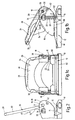
- the paper punch shown in Fig. 1a and b consists essentially of a on the bottom side through a collecting trough 10 for punched-out paper chips closable lower part 12, two at a lateral distance from one another rigidly attached to the lower part 12, with the lower part 12 an insertion slot 14 for the lateral bearing pedestals delimiting the documents to be punched 16 and one pivotable about the axis 18 on the bearing blocks 16 stored, on on the lower part slidably guided punch 20 against the restoring force of a spring 22 acting pressure lever 24.
- the pressure lever 24 has a U-shaped wire bracket bent from a round wire 26 on, the two via a rear strap 28 with each other connected bracket leg 30.
- the wire bracket is attached by means of a the free ends 39 of its bracket legs 30 arranged bearing 32nd mounted on one of the bearing blocks 16 and lies with its bracket legs 30 at a distance from the bearing point 32 against a rear end face 34 the punch 20.
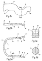
- the wire bracket 26 consists of a curved Round wire, the bearing points 32 by open edge bending at the Bow legs 30 are formed. Located at a distance from the bend 32 there is a transverse notch 36 with which the stirrup legs 30 against the punch 20 concerns.
- the bearing blocks 16 have bearing journals facing each other 38 for receiving one of the bearings 32 of the wire bracket 26 on. As can be seen from Fig.
- the wire bracket 26 is in the assembly in Direction of arrow 40 with the free ends of its stirrup legs 30 in the Area between the respective journal 38 and the punch 20 introduced and then pivoted so that the bend 32 against the bearing pin 38 abuts, the free projecting leg end 39 against a stop 42 located on the respective bearing block 16 abuts and the Cross notch 36 is supported against the end face 34 of the respective punch 20 is.
- bracket web 28 and the two bracket legs 30 free space 44 is bridged by a separate cover part, the is designed as a plastic molding and snapped onto the wire bracket 26 is.
- the wire bracket 26 has on its bracket legs one notch 48 each, while the cover part with in the notches 48 snap-in locking elements 50 is provided.
- the cover part 46 provides the bearing points 32 and the bearing pins with one each 38 comprehensive locking section 52 for that when the cover part is snapped on the wire bracket can no longer detach from its swivel bearing. Further are arranged on the cover part 46 deflectors 54, which ensure that no undesirable between the pressure lever 24 and the bearing blocks 16 Pinching occurs.
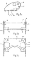
- the bearing blocks 16, which are preferably designed as stamped sheet metal parts bounded by an inwardly curved edge 56, each of which is an open edge Notch 58 has for the passage of one of the stirrup legs.
- the notch 58 is at least on one side by a End stop for the relevant bracket leg 30 formed stop edge 60 limited.
- the bearing blocks 16 in one piece by a fastened to a base part 62 of the lower part 12 Assembly web 64 connected to each other, the assembly web 64 and the base part 62, the insertion slot 14 for the paper to be punched limit. Furthermore, the bearing blocks 16 each have a base part 62 of the Lochers engaging under retaining anchor 66, which ensures that the insertion slot 14 is not bent open in the case of heavy perforations.
- the assembly bridge 64 is in the embodiment shown both on the side Retaining anchors 66 and rivets which extend through the bores 68, connected to the base part 62.
- the invention relates to a paper punch with a lower part 12 and one on the side bracket 16 of the lower part pivotally mounted on the lower part 12 guided punch 20 against the restoring force of a spring 22nd acting pressure lever.
- a particularly simple and easy to assemble Structure of the paper punch is obtained when the pressure lever 24 is one U-shaped wire bracket that has two over a rear strap 28 interconnected stirrup legs 30.
- the wire bracket 26 is arranged by means of one each at the free ends of its bracket legs 30
- Bearing 32 is mounted on one of the bearing blocks 16 and lies with his bow legs 30 at a distance from the bearing point 32 immediately against a rear end face 34 of the punch.
- the one through the Strap web 28 and the two strap legs 30 limited free space can at least partially by a separate, preferably from Plastic cover part 46 are bridged.
Landscapes
- Life Sciences & Earth Sciences (AREA)
- Forests & Forestry (AREA)
- Engineering & Computer Science (AREA)
- Mechanical Engineering (AREA)
- Perforating, Stamping-Out Or Severing By Means Other Than Cutting (AREA)
- Developing Agents For Electrophotography (AREA)
- Polishing Bodies And Polishing Tools (AREA)
- Paper (AREA)
Description
- Fig. 1a
- und b eine Vorderansicht und eine Seitenansicht eines Papierlochers;
- Fig. 2
- einen Ausschnitt aus Fig. 1b bei der Montage des Druckhebel-Drahtbügels;
- Fig. 3a
- und b eine Draufsicht und eine Seitenansicht des Drahtbügels;
- Fig. 3c
- einen vergrößerten Ausschnitt aus Fig. 3b im Bereich der Lagersteile;
- Fig. 3d
- einen Schnitt entlang der Schnittlinie D-D der Fig. 3a;
- Fig. 3e
- einen Schnitt entlang der Schnittlinie E-E der Fig. 3c;
- Fig. 4a
- bis d eine Draufsicht, eine Seitenansicht, eine Stimseitenansicht und eine Untenansicht des Druckhebel-Deckelteils;
- Fig. 4e
- einen Schnitt entlang der Schnittlinie E-E der Fig. 4d;
- Fig. 5a
- bis c eine Seitenansicht, eine Stimseitenansicht und eine Draufsicht des die Lagerböcke des Lochers enthaltenden geprägten Blechbiegeteils.
Claims (17)
- Papierlocher mit einem Unterteil (12) und einem an seitlichen Lagerböcken (16) des Unterteils (12) schwenkbar gelagerten, auf am Unterteil (12) verschiebbar geführte Lochstempel (20) gegen die Rückstellkraft einer Feder (22) einwirkenden Druckhebel (24), wobei der Druckhebel (24) zwei Seitenschenkel (30) aufweist und mittels je einem an den freien Enden der Seitenschenkel (30) angeordneten Lagerstellen (32) an je einem der Lagerböcke (16) gelagert ist und mit seinen Seitenschenkeln (30) im Abstand von der jeweiligen Lagerstelle (32) unmittelbar gegen eine rückwärtige Stirnfläche (34) der Lochstempel (20) anliegt, dadurch gekennzeichnet, daß der Druckhebel (24) einen Drahtbügel (26) aufweist, der zwei über einen rückwärtigen Bügelsteg (28) miteinander verbundene, die Seitenschenkel bildende Bügelschenkel (30) aufweist und daß die Bügelschenkel (30) mit ihren über die Lagerstellen überstehenden freien Schenkelenden (39) gegen einen am jeweiligen Lagerbock (16) angeordneten Anschlag abgestützt sind.
- Papierlocher nach Anspruch 1, dadurch gekennzeichnet, daß der durch den Bügelsteg (28) und die beiden Bügelschenkel (30) begrenzte freie Zwischenraum (44) zumindest teilweise durch ein separates Dekkelteil (46) überbrückt ist.
- Papierlocher nach Anspruch 2, dadurch gekennzeichnet, daß das Deckelteil (46) als Kunststoff-Formteil ausgebildet ist.
- Papierlocher nach Anspruch 2 oder 3, dadurch gekennzeichnet, daß das Deckelteil (46) auf den Drahtbügel (26) aufgerastet ist.
- Papierlocher nach einem der Ansprüche 2 bis 4, dadurch gekennzeichnet, daß der Drahtbügel (26) zumindest an seinen Bügelschenkeln Rastkerben (48) aufweist, und daß das Deckelteil (46) mit in die Rastkerben (48) des Drahtbügels (26) einrastbaren Rastelementen (50) versehen ist.
- Papierlocher nach einem der Ansprüche 1 bis 5, dadurch gekennzeichnet, daß die Lagerböcke (16) einander zugewandte Lagerzapfen (38) oder eine Steckachse zur Aufnahme je einer der Lagerstellen (32) des Drahtbügels (26) aufweisen.
- Papierlocher nach einem der Ansprüche 2 bis 5, dadurch gekennzeichnet, daß das Deckelteil (46) eine die Lagerstelle (32) des Drahtbügels (26) übergreifende Sperrpartie (52) aufweist.
- Papierlocher nach einem der Ansprüche 1 bis 7, dadurch gekennzeichnet, daß die als Blechprägeteile oder Blechbiegeteile ausgebildeten Lagerböcke (16) durch einen nach innen gebogenen Rand (56) begrenzt sind, der jeweils eine randoffene Ausklinkung (58) für den Durchtritt eines der Bügelschenkel (30) aufweist.
- Papierlocher nach Anspruch 8, dadurch gekennzeichnet, daß die Ausklinkung (58) durch eine als Endanschlag für den betreffenden Bügelschenkel (30) ausgebildete Anschlagkante (60) begrenzt ist.
- Papierlocher nach einem der Ansprüche 1 bis 9, dadurch gekennzeichnet, daß die Lagerstellen (32) durch teilkreisförmige randoffene Ausbiegungen an den Bügelschenkeln (30) gebildet sind.
- Papierlocher nach einem der Ansprüche 1 bis 9, dadurch gekennzeichnet, daß die Lagerstellen (32) durch um etwa 90° abgebogene, in entsprechende Lageraugen der Lagerböcke (16) eingreifende Bügelenden gebildet sind.
- Papierlocher nach einem der Ansprüche 1 bis 11, dadurch gekennzeichnet, daß der Drahtbügel (26) aus einem Runddraht besteht.
- Papierlocher nach einem der Ansprüche 1 bis 12, dadurch gekennzeichnet, daß die Bügelschenkel (30) im Bereich der Lagerstellen (32) flachgeprägt sind.
- Papierlocher nach einem der Ansprüche 6 bis 13, dadurch gekennzeichnet, daß die Lagerstellen (32) als Lageraugen zur Aufnahme eines Lagerzapfens oder einer Steckachse ausgebildet sind.
- Papierlocher nach einem der Ansprüche 1 bis 14, dadurch gekennzeichnet, daß die Lagerböcke (16) einstückig durch einen an einem Basisteil (62) des Lochers befestigbaren Montagesteg (64) verbunden sind, wobei der Montagesteg (64) und das Basisteil (62) einen Einschubschlitz (14) für das zu lochende Papier begrenzen.
- Papierlocher nach einem der Ansprüche 1 bis 15, dadurch gekennzeichnet, daß die Lagerböcke (16) je einen das Basisteil (62) des Lochers untergreifenden Halteanker (66) aufweisen.
- Papierlocher nach Anspruch 15 oder 16, dadurch gekennzeichnet, daß der Montagesteg (64) mit dem Basisteil (62) vernietet, verschweißt, verlötet oder verklebt ist.
Applications Claiming Priority (3)
| Application Number | Priority Date | Filing Date | Title |
|---|---|---|---|
| DE19912043 | 1999-03-17 | ||
| DE19912043A DE19912043A1 (de) | 1999-03-17 | 1999-03-17 | Papierlocher |
| PCT/EP2000/000446 WO2000054943A1 (de) | 1999-03-17 | 2000-01-21 | Papierlocher |
Publications (2)
| Publication Number | Publication Date |
|---|---|
| EP1161328A1 EP1161328A1 (de) | 2001-12-12 |
| EP1161328B1 true EP1161328B1 (de) | 2002-11-27 |
Family
ID=7901402
Family Applications (1)
| Application Number | Title | Priority Date | Filing Date |
|---|---|---|---|
| EP00903600A Expired - Lifetime EP1161328B1 (de) | 1999-03-17 | 2000-01-21 | Papierlocher |
Country Status (5)
| Country | Link |
|---|---|
| EP (1) | EP1161328B1 (de) |
| AT (1) | ATE228419T1 (de) |
| DE (2) | DE19912043A1 (de) |
| ES (1) | ES2186625T3 (de) |
| WO (1) | WO2000054943A1 (de) |
Families Citing this family (2)
| Publication number | Priority date | Publication date | Assignee | Title |
|---|---|---|---|---|
| DE10134025B4 (de) * | 2001-07-12 | 2006-08-03 | Novus Gmbh & Co. Kg | Papierlocher |
| DE102008033606B4 (de) | 2008-07-17 | 2019-05-09 | Leitz Acco Brands Gmbh & Co Kg | Papierlocher |
Citations (2)
| Publication number | Priority date | Publication date | Assignee | Title |
|---|---|---|---|---|
| DE364582C (de) * | 1922-11-28 | Leopold Kramer | Locher, dessen Boecke fuer die Lochstempel fuer zwei verschiedene Lochweiten durch einen gemeinschaftlichen Antrieb verstellt werden koennen | |
| US3898919A (en) * | 1973-12-28 | 1975-08-12 | Jr David Grimaldi | Sheet perforator having means for reinforcing the sheet at the holes |
Family Cites Families (14)
| Publication number | Priority date | Publication date | Assignee | Title |
|---|---|---|---|---|
| FR955676A (de) * | 1950-01-18 | |||
| DE368462C (de) * | 1923-02-06 | Giuseppe Tonelli | Briefordnermechanik mit einer beim Schliessen der Aufreihbuegel in Taetigkeit tretenden Lochvorrichtung | |
| US1174883A (en) * | 1915-07-02 | 1916-03-07 | John Mcluckie | Paper-punch. |
| US1692764A (en) * | 1926-12-13 | 1928-11-20 | Globe Wernicke Co | Punch |
| US2638986A (en) * | 1947-08-29 | 1953-05-19 | Gen Binding Corp | Portable punching machine |
| DE1765420U (de) * | 1957-12-27 | 1958-04-24 | Walter Liebold K G | Tischlocher zum gleichzeitigen herstellen einer vielzahl rechteckiger locher in papierblaettern, folien u. dgl. |
| US4036088A (en) * | 1976-08-30 | 1977-07-19 | Rolodex Corporation | Paper punch with variable spacing |
| FR2441468A1 (fr) * | 1978-11-16 | 1980-06-13 | Martin Rene | Perforateur pour la realisation de feuillets perfores utilisables dans des reliures a broches classiques |
| DE7902626U1 (de) * | 1979-01-29 | 1979-07-19 | Rosa, Franz, 1000 Berlin | Geraet zum heften und lochen von schriftgut o.dgl. |
| DE2940384A1 (de) * | 1979-10-05 | 1981-04-16 | Fa. Louis Leitz, 7000 Stuttgart | Brieflocher-unterteil |
| US4640451A (en) * | 1982-11-08 | 1987-02-03 | Kollektivgesellschaft Eberhard, Steiner & Dr. Stocker | Combination hole punch and stapler |
| DE3326479C2 (de) * | 1983-07-22 | 1985-06-05 | Brause GmbH & Co, 5860 Iserlohn | Brieflocher |
| DE9006032U1 (de) * | 1990-05-29 | 1990-08-02 | Elba-Ordner-Fabrik Kraut & Meienborn Gmbh & Co, 5600 Wuppertal | Locher für Schriftgut |
| DE4216361A1 (de) * | 1992-05-18 | 1994-04-21 | Peter Keck | Bürolocher |
-
1999
- 1999-03-17 DE DE19912043A patent/DE19912043A1/de not_active Withdrawn
-
2000
- 2000-01-21 EP EP00903600A patent/EP1161328B1/de not_active Expired - Lifetime
- 2000-01-21 AT AT00903600T patent/ATE228419T1/de active
- 2000-01-21 ES ES00903600T patent/ES2186625T3/es not_active Expired - Lifetime
- 2000-01-21 WO PCT/EP2000/000446 patent/WO2000054943A1/de not_active Ceased
- 2000-01-21 DE DE50000829T patent/DE50000829D1/de not_active Expired - Lifetime
Patent Citations (2)
| Publication number | Priority date | Publication date | Assignee | Title |
|---|---|---|---|---|
| DE364582C (de) * | 1922-11-28 | Leopold Kramer | Locher, dessen Boecke fuer die Lochstempel fuer zwei verschiedene Lochweiten durch einen gemeinschaftlichen Antrieb verstellt werden koennen | |
| US3898919A (en) * | 1973-12-28 | 1975-08-12 | Jr David Grimaldi | Sheet perforator having means for reinforcing the sheet at the holes |
Also Published As
| Publication number | Publication date |
|---|---|
| EP1161328A1 (de) | 2001-12-12 |
| WO2000054943A1 (de) | 2000-09-21 |
| DE19912043A1 (de) | 2000-09-21 |
| DE50000829D1 (de) | 2003-01-09 |
| ES2186625T3 (es) | 2003-05-16 |
| ATE228419T1 (de) | 2002-12-15 |
Similar Documents
| Publication | Publication Date | Title |
|---|---|---|
| DE69922105T2 (de) | Rasthaken | |
| DE3140878C2 (de) | ||
| DE3433106C2 (de) | Wischarm, insbesondere für Wischanlagen an Kraftfahrzeugen | |
| DE19500192C1 (de) | Elastisches Lager zur Aufhängung eines dynamisch beanspruchten Funktionsteils | |
| WO2001094166A1 (de) | Scheibenwischer für kraftfahrzeuge | |
| DE1930638B2 (de) | Scheibenwischer fuer kraftfahrzeuge | |
| EP1875107B1 (de) | Zugmitteltrieb mit zumindest einer schiene zum spannen und/oder führen eines endlosen zugmittels | |
| DE102008046583A1 (de) | Printklemme | |
| DE29715114U1 (de) | Baugruppenträger | |
| DE102009045672A1 (de) | Wischblatt in Flachbalkenbauweise | |
| DE69704035T2 (de) | Befestigungsteil für Kraftfahrzeug-Scheibenwischer | |
| EP2797785B1 (de) | Wischblattvorrichtung | |
| WO2000054943A1 (de) | Papierlocher | |
| DE102017206462B4 (de) | System zur fixierung einer abdeckung an einem gepäckbehälter | |
| WO2019042717A1 (de) | Federteller | |
| DE2607365C2 (de) | Wischvorrichtung für Scheiben von Kraftfahrzeugen | |
| DE2643833A1 (de) | Halterung fuer die lamelle eines lamellenventils | |
| DE8002883U1 (de) | Kunststoff-Clip zur Befestigung von Verkleidungen in Kraftfahrzeugen o.dgl | |
| DE10239151A1 (de) | Aufhängeteil | |
| DE102022122055B4 (de) | Lenkrad mit einem Airbagmodul | |
| DE102006041803B4 (de) | Vorrichtung zur Befestigung eines Gerätes an einer Tragschiene | |
| EP0071780B1 (de) | Aufhängevorrichtung für Briefordner | |
| AT217747B (de) | Handgriff für Grabwerkzeuge | |
| DE10148969B4 (de) | Stellantrieb für ein Fahrzeug | |
| DE3337508A1 (de) | Gurtschloss fuer einen sicherheitsgurt |
Legal Events
| Date | Code | Title | Description |
|---|---|---|---|
| PUAI | Public reference made under article 153(3) epc to a published international application that has entered the european phase |
Free format text: ORIGINAL CODE: 0009012 |
|
| 17P | Request for examination filed |
Effective date: 20010804 |
|
| AK | Designated contracting states |
Kind code of ref document: A1 Designated state(s): AT BE CH CY DE DK ES FI FR GB GR IE IT LI LU MC NL PT SE |
|
| RIN1 | Information on inventor provided before grant (corrected) |
Inventor name: PFLUGFELDER, THEODOR Inventor name: JUESTEL, REINER Inventor name: RADU, BRIGITTE Inventor name: FRANK, STEFAN Inventor name: LABONDE, STEFAN Inventor name: SIEGHART, GERHARD Inventor name: PFRUENDER, HORST Inventor name: DECKER, MARTIN |
|
| RIN1 | Information on inventor provided before grant (corrected) |
Inventor name: RADU, BRIGITTE Inventor name: FRANK, STEFAN Inventor name: PFRUENDER, HORST Inventor name: PFLUGFELDER, THEODOR Inventor name: SIEGHART, GERHARD Inventor name: DECKER, MARTIN Inventor name: JUESTEL, REINER Inventor name: LABONDE, STEFAN |
|
| GRAG | Despatch of communication of intention to grant |
Free format text: ORIGINAL CODE: EPIDOS AGRA |
|
| 17Q | First examination report despatched |
Effective date: 20020319 |
|
| GRAG | Despatch of communication of intention to grant |
Free format text: ORIGINAL CODE: EPIDOS AGRA |
|
| GRAG | Despatch of communication of intention to grant |
Free format text: ORIGINAL CODE: EPIDOS AGRA |
|
| GRAH | Despatch of communication of intention to grant a patent |
Free format text: ORIGINAL CODE: EPIDOS IGRA |
|
| GRAH | Despatch of communication of intention to grant a patent |
Free format text: ORIGINAL CODE: EPIDOS IGRA |
|
| GRAA | (expected) grant |
Free format text: ORIGINAL CODE: 0009210 |
|
| AK | Designated contracting states |
Kind code of ref document: B1 Designated state(s): AT BE CH CY DE DK ES FI FR GB GR IE IT LI LU MC NL PT SE |
|
| PG25 | Lapsed in a contracting state [announced via postgrant information from national office to epo] |
Ref country code: IT Free format text: LAPSE BECAUSE OF FAILURE TO SUBMIT A TRANSLATION OF THE DESCRIPTION OR TO PAY THE FEE WITHIN THE PRESCRIBED TIME-LIMIT;WARNING: LAPSES OF ITALIAN PATENTS WITH EFFECTIVE DATE BEFORE 2007 MAY HAVE OCCURRED AT ANY TIME BEFORE 2007. THE CORRECT EFFECTIVE DATE MAY BE DIFFERENT FROM THE ONE RECORDED. Effective date: 20021127 Ref country code: GR Free format text: LAPSE BECAUSE OF FAILURE TO SUBMIT A TRANSLATION OF THE DESCRIPTION OR TO PAY THE FEE WITHIN THE PRESCRIBED TIME-LIMIT Effective date: 20021127 Ref country code: IE Free format text: LAPSE BECAUSE OF FAILURE TO SUBMIT A TRANSLATION OF THE DESCRIPTION OR TO PAY THE FEE WITHIN THE PRESCRIBED TIME-LIMIT Effective date: 20021127 Ref country code: FI Free format text: LAPSE BECAUSE OF FAILURE TO SUBMIT A TRANSLATION OF THE DESCRIPTION OR TO PAY THE FEE WITHIN THE PRESCRIBED TIME-LIMIT Effective date: 20021127 |
|
| REF | Corresponds to: |
Ref document number: 228419 Country of ref document: AT Date of ref document: 20021215 Kind code of ref document: T |
|
| REG | Reference to a national code |
Ref country code: GB Ref legal event code: FG4D Free format text: NOT ENGLISH |
|
| REG | Reference to a national code |
Ref country code: CH Ref legal event code: EP |
|
| REG | Reference to a national code |
Ref country code: IE Ref legal event code: FG4D Free format text: GERMAN |
|
| REF | Corresponds to: |
Ref document number: 50000829 Country of ref document: DE Date of ref document: 20030109 |
|
| PG25 | Lapsed in a contracting state [announced via postgrant information from national office to epo] |
Ref country code: LU Free format text: LAPSE BECAUSE OF NON-PAYMENT OF DUE FEES Effective date: 20030121 Ref country code: CY Free format text: LAPSE BECAUSE OF FAILURE TO SUBMIT A TRANSLATION OF THE DESCRIPTION OR TO PAY THE FEE WITHIN THE PRESCRIBED TIME-LIMIT Effective date: 20030121 |
|
| REG | Reference to a national code |
Ref country code: FR Ref legal event code: GC |
|
| PG25 | Lapsed in a contracting state [announced via postgrant information from national office to epo] |
Ref country code: MC Free format text: LAPSE BECAUSE OF NON-PAYMENT OF DUE FEES Effective date: 20030131 |
|
| GBT | Gb: translation of ep patent filed (gb section 77(6)(a)/1977) |
Effective date: 20030120 |
|
| PG25 | Lapsed in a contracting state [announced via postgrant information from national office to epo] |
Ref country code: PT Free format text: LAPSE BECAUSE OF FAILURE TO SUBMIT A TRANSLATION OF THE DESCRIPTION OR TO PAY THE FEE WITHIN THE PRESCRIBED TIME-LIMIT Effective date: 20030227 Ref country code: SE Free format text: LAPSE BECAUSE OF FAILURE TO SUBMIT A TRANSLATION OF THE DESCRIPTION OR TO PAY THE FEE WITHIN THE PRESCRIBED TIME-LIMIT Effective date: 20030227 Ref country code: DK Free format text: LAPSE BECAUSE OF FAILURE TO SUBMIT A TRANSLATION OF THE DESCRIPTION OR TO PAY THE FEE WITHIN THE PRESCRIBED TIME-LIMIT Effective date: 20030227 |
|
| REG | Reference to a national code |
Ref country code: GB Ref legal event code: 732E |
|
| REG | Reference to a national code |
Ref country code: ES Ref legal event code: FG2A Ref document number: 2186625 Country of ref document: ES Kind code of ref document: T3 |
|
| ET | Fr: translation filed | ||
| REG | Reference to a national code |
Ref country code: IE Ref legal event code: FD4D Ref document number: 1161328E Country of ref document: IE |
|
| PLBE | No opposition filed within time limit |
Free format text: ORIGINAL CODE: 0009261 |
|
| STAA | Information on the status of an ep patent application or granted ep patent |
Free format text: STATUS: NO OPPOSITION FILED WITHIN TIME LIMIT |
|
| 26N | No opposition filed |
Effective date: 20030828 |
|
| REG | Reference to a national code |
Ref country code: FR Ref legal event code: RG |
|
| PGFP | Annual fee paid to national office [announced via postgrant information from national office to epo] |
Ref country code: AT Payment date: 20110113 Year of fee payment: 12 |
|
| PGFP | Annual fee paid to national office [announced via postgrant information from national office to epo] |
Ref country code: BE Payment date: 20110104 Year of fee payment: 12 |
|
| BERE | Be: lapsed |
Owner name: *ESSELTE LEITZ G.M.B.H. & CO. K.G. Effective date: 20120131 |
|
| REG | Reference to a national code |
Ref country code: AT Ref legal event code: MM01 Ref document number: 228419 Country of ref document: AT Kind code of ref document: T Effective date: 20120121 |
|
| PG25 | Lapsed in a contracting state [announced via postgrant information from national office to epo] |
Ref country code: BE Free format text: LAPSE BECAUSE OF NON-PAYMENT OF DUE FEES Effective date: 20120131 |
|
| PG25 | Lapsed in a contracting state [announced via postgrant information from national office to epo] |
Ref country code: AT Free format text: LAPSE BECAUSE OF NON-PAYMENT OF DUE FEES Effective date: 20120121 |
|
| PGFP | Annual fee paid to national office [announced via postgrant information from national office to epo] |
Ref country code: CH Payment date: 20140121 Year of fee payment: 15 |
|
| REG | Reference to a national code |
Ref country code: FR Ref legal event code: PLFP Year of fee payment: 16 |
|
| REG | Reference to a national code |
Ref country code: DE Ref legal event code: R082 Ref document number: 50000829 Country of ref document: DE Representative=s name: PATENTANWAELTE BREGENZER UND REULE PARTNERSCHA, DE |
|
| REG | Reference to a national code |
Ref country code: FR Ref legal event code: GC Effective date: 20150310 |
|
| PGFP | Annual fee paid to national office [announced via postgrant information from national office to epo] |
Ref country code: FR Payment date: 20150122 Year of fee payment: 16 Ref country code: GB Payment date: 20150121 Year of fee payment: 16 |
|
| REG | Reference to a national code |
Ref country code: CH Ref legal event code: PL |
|
| PG25 | Lapsed in a contracting state [announced via postgrant information from national office to epo] |
Ref country code: LI Free format text: LAPSE BECAUSE OF NON-PAYMENT OF DUE FEES Effective date: 20150131 Ref country code: CH Free format text: LAPSE BECAUSE OF NON-PAYMENT OF DUE FEES Effective date: 20150131 |
|
| PGFP | Annual fee paid to national office [announced via postgrant information from national office to epo] |
Ref country code: NL Payment date: 20160120 Year of fee payment: 17 |
|
| GBPC | Gb: european patent ceased through non-payment of renewal fee |
Effective date: 20160121 |
|
| REG | Reference to a national code |
Ref country code: FR Ref legal event code: ST Effective date: 20160930 |
|
| PG25 | Lapsed in a contracting state [announced via postgrant information from national office to epo] |
Ref country code: GB Free format text: LAPSE BECAUSE OF NON-PAYMENT OF DUE FEES Effective date: 20160121 |
|
| PG25 | Lapsed in a contracting state [announced via postgrant information from national office to epo] |
Ref country code: FR Free format text: LAPSE BECAUSE OF NON-PAYMENT OF DUE FEES Effective date: 20160201 |
|
| PGFP | Annual fee paid to national office [announced via postgrant information from national office to epo] |
Ref country code: ES Payment date: 20170113 Year of fee payment: 18 |
|
| REG | Reference to a national code |
Ref country code: FR Ref legal event code: RG Effective date: 20170726 |
|
| REG | Reference to a national code |
Ref country code: NL Ref legal event code: MM Effective date: 20170201 |
|
| PG25 | Lapsed in a contracting state [announced via postgrant information from national office to epo] |
Ref country code: NL Free format text: LAPSE BECAUSE OF NON-PAYMENT OF DUE FEES Effective date: 20170201 |
|
| REG | Reference to a national code |
Ref country code: DE Ref legal event code: R082 Ref document number: 50000829 Country of ref document: DE Representative=s name: PATENTANWAELTE BREGENZER UND REULE PARTNERSCHA, DE Ref country code: DE Ref legal event code: R081 Ref document number: 50000829 Country of ref document: DE Owner name: LEITZ ACCO BRANDS GMBH & CO KG, DE Free format text: FORMER OWNER: ESSELTE LEITZ GMBH & CO. KG, 70469 STUTTGART, DE |
|
| PGFP | Annual fee paid to national office [announced via postgrant information from national office to epo] |
Ref country code: DE Payment date: 20181129 Year of fee payment: 20 |
|
| REG | Reference to a national code |
Ref country code: ES Ref legal event code: FD2A Effective date: 20190731 |
|
| PG25 | Lapsed in a contracting state [announced via postgrant information from national office to epo] |
Ref country code: ES Free format text: LAPSE BECAUSE OF NON-PAYMENT OF DUE FEES Effective date: 20180122 |
|
| REG | Reference to a national code |
Ref country code: DE Ref legal event code: R071 Ref document number: 50000829 Country of ref document: DE |