EP1160116A2 - Instrument combiné pour un véhicule automobile - Google Patents
Instrument combiné pour un véhicule automobile Download PDFInfo
- Publication number
- EP1160116A2 EP1160116A2 EP01111900A EP01111900A EP1160116A2 EP 1160116 A2 EP1160116 A2 EP 1160116A2 EP 01111900 A EP01111900 A EP 01111900A EP 01111900 A EP01111900 A EP 01111900A EP 1160116 A2 EP1160116 A2 EP 1160116A2
- Authority
- EP
- European Patent Office
- Prior art keywords
- light
- guide plate
- light guide
- display
- instrument cluster
- Prior art date
- Legal status (The legal status is an assumption and is not a legal conclusion. Google has not performed a legal analysis and makes no representation as to the accuracy of the status listed.)
- Withdrawn
Links
- 239000011248 coating agent Substances 0.000 claims abstract description 16
- 238000000576 coating method Methods 0.000 claims abstract description 16
- 230000008878 coupling Effects 0.000 claims abstract description 12
- 238000010168 coupling process Methods 0.000 claims abstract description 12
- 238000005859 coupling reaction Methods 0.000 claims abstract description 12
- 229920003023 plastic Polymers 0.000 claims description 3
- 230000007704 transition Effects 0.000 claims description 3
- 230000003287 optical effect Effects 0.000 abstract 1
- 230000008901 benefit Effects 0.000 description 3
- 238000001514 detection method Methods 0.000 description 3
- 239000000243 solution Substances 0.000 description 3
- 230000001143 conditioned effect Effects 0.000 description 2
- 230000001419 dependent effect Effects 0.000 description 2
- 230000004907 flux Effects 0.000 description 2
- 238000005286 illumination Methods 0.000 description 2
- 238000002347 injection Methods 0.000 description 2
- 239000007924 injection Substances 0.000 description 2
- 238000009434 installation Methods 0.000 description 2
- 240000003517 Elaeocarpus dentatus Species 0.000 description 1
- 230000008859 change Effects 0.000 description 1
- 230000003750 conditioning effect Effects 0.000 description 1
- 238000011161 development Methods 0.000 description 1
- 230000018109 developmental process Effects 0.000 description 1
- 238000005516 engineering process Methods 0.000 description 1
- 230000004313 glare Effects 0.000 description 1
- 230000001771 impaired effect Effects 0.000 description 1
- 230000001795 light effect Effects 0.000 description 1
- 239000004973 liquid crystal related substance Substances 0.000 description 1
- 239000000203 mixture Substances 0.000 description 1
- 229920000642 polymer Polymers 0.000 description 1
- 239000002918 waste heat Substances 0.000 description 1
Images
Classifications
-
- B60K35/60—
-
- G—PHYSICS
- G02—OPTICS
- G02F—OPTICAL DEVICES OR ARRANGEMENTS FOR THE CONTROL OF LIGHT BY MODIFICATION OF THE OPTICAL PROPERTIES OF THE MEDIA OF THE ELEMENTS INVOLVED THEREIN; NON-LINEAR OPTICS; FREQUENCY-CHANGING OF LIGHT; OPTICAL LOGIC ELEMENTS; OPTICAL ANALOGUE/DIGITAL CONVERTERS
- G02F1/00—Devices or arrangements for the control of the intensity, colour, phase, polarisation or direction of light arriving from an independent light source, e.g. switching, gating or modulating; Non-linear optics
- G02F1/01—Devices or arrangements for the control of the intensity, colour, phase, polarisation or direction of light arriving from an independent light source, e.g. switching, gating or modulating; Non-linear optics for the control of the intensity, phase, polarisation or colour
- G02F1/13—Devices or arrangements for the control of the intensity, colour, phase, polarisation or direction of light arriving from an independent light source, e.g. switching, gating or modulating; Non-linear optics for the control of the intensity, phase, polarisation or colour based on liquid crystals, e.g. single liquid crystal display cells
- G02F1/133—Constructional arrangements; Operation of liquid crystal cells; Circuit arrangements
- G02F1/1333—Constructional arrangements; Manufacturing methods
- G02F1/1335—Structural association of cells with optical devices, e.g. polarisers or reflectors
- G02F1/1336—Illuminating devices
- G02F1/133615—Edge-illuminating devices, i.e. illuminating from the side
-
- G—PHYSICS
- G02—OPTICS
- G02F—OPTICAL DEVICES OR ARRANGEMENTS FOR THE CONTROL OF LIGHT BY MODIFICATION OF THE OPTICAL PROPERTIES OF THE MEDIA OF THE ELEMENTS INVOLVED THEREIN; NON-LINEAR OPTICS; FREQUENCY-CHANGING OF LIGHT; OPTICAL LOGIC ELEMENTS; OPTICAL ANALOGUE/DIGITAL CONVERTERS
- G02F1/00—Devices or arrangements for the control of the intensity, colour, phase, polarisation or direction of light arriving from an independent light source, e.g. switching, gating or modulating; Non-linear optics
- G02F1/01—Devices or arrangements for the control of the intensity, colour, phase, polarisation or direction of light arriving from an independent light source, e.g. switching, gating or modulating; Non-linear optics for the control of the intensity, phase, polarisation or colour
- G02F1/13—Devices or arrangements for the control of the intensity, colour, phase, polarisation or direction of light arriving from an independent light source, e.g. switching, gating or modulating; Non-linear optics for the control of the intensity, phase, polarisation or colour based on liquid crystals, e.g. single liquid crystal display cells
- G02F1/133—Constructional arrangements; Operation of liquid crystal cells; Circuit arrangements
- G02F1/1333—Constructional arrangements; Manufacturing methods
- G02F1/1335—Structural association of cells with optical devices, e.g. polarisers or reflectors
- G02F1/1336—Illuminating devices
- G02F1/133618—Illuminating devices for ambient light
-
- G—PHYSICS
- G02—OPTICS
- G02F—OPTICAL DEVICES OR ARRANGEMENTS FOR THE CONTROL OF LIGHT BY MODIFICATION OF THE OPTICAL PROPERTIES OF THE MEDIA OF THE ELEMENTS INVOLVED THEREIN; NON-LINEAR OPTICS; FREQUENCY-CHANGING OF LIGHT; OPTICAL LOGIC ELEMENTS; OPTICAL ANALOGUE/DIGITAL CONVERTERS
- G02F1/00—Devices or arrangements for the control of the intensity, colour, phase, polarisation or direction of light arriving from an independent light source, e.g. switching, gating or modulating; Non-linear optics
- G02F1/01—Devices or arrangements for the control of the intensity, colour, phase, polarisation or direction of light arriving from an independent light source, e.g. switching, gating or modulating; Non-linear optics for the control of the intensity, phase, polarisation or colour
- G02F1/13—Devices or arrangements for the control of the intensity, colour, phase, polarisation or direction of light arriving from an independent light source, e.g. switching, gating or modulating; Non-linear optics for the control of the intensity, phase, polarisation or colour based on liquid crystals, e.g. single liquid crystal display cells
- G02F1/133—Constructional arrangements; Operation of liquid crystal cells; Circuit arrangements
- G02F1/1333—Constructional arrangements; Manufacturing methods
- G02F1/1335—Structural association of cells with optical devices, e.g. polarisers or reflectors
- G02F1/1336—Illuminating devices
- G02F1/133626—Illuminating devices providing two modes of illumination, e.g. day-night
-
- G—PHYSICS
- G02—OPTICS
- G02F—OPTICAL DEVICES OR ARRANGEMENTS FOR THE CONTROL OF LIGHT BY MODIFICATION OF THE OPTICAL PROPERTIES OF THE MEDIA OF THE ELEMENTS INVOLVED THEREIN; NON-LINEAR OPTICS; FREQUENCY-CHANGING OF LIGHT; OPTICAL LOGIC ELEMENTS; OPTICAL ANALOGUE/DIGITAL CONVERTERS
- G02F2201/00—Constructional arrangements not provided for in groups G02F1/00 - G02F7/00
- G02F2201/58—Arrangements comprising a monitoring photodetector
Definitions
- the present invention relates to an instrument cluster for a motor vehicle, especially for a commercial vehicle or a bus, with an LC display.
- instrument clusters are varied due to their use in Motor vehicles known. They usually come in a single housing a plurality of display devices and a inform the driver about various operating states of the motor vehicle.
- the carrier plate is often designed as an electrical circuit board.
- an instrument cluster increasingly also an LC display, i.e. a liquid crystal display.
- LC display i.e. a liquid crystal display.
- In one Commercial vehicles or in a bus are mostly flat Instrument cluster in the dashboard under one opposite the Horizontal inclined angle of typically 20 ° to 50 ° installed which has the advantage that large and therefore particularly clear Arrangements of instruments and electronic displays, including one LC display, are possible.
- the contrast enhancement according to the invention has the advantage without the use to make do with additional active electrical light sources.
- a with Instrument cluster equipped with the above features does not have a) higher electrical energy requirements, b) does not require a larger number of electrical components, c) produces none with electrical light sources unavoidable waste heat and d) is inexpensive to implement because the Light guide plate can be manufactured in almost any shape as an injection molded part can.
- the proposed approach is based on the fact that the disturbing incidence of light is used for backlighting the LC display. Because the incident luminous flux is collected behind the LC display is directed and there caused to the concentrated exit, the Increase the contrast of displays on the LC display just when a contrast enhancement is most urgently needed, namely at intense ambient light, such as during the day when bright sunlight.
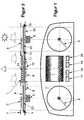
- FIGS. 1 and 2 are explained here in context since they show the same instrument cluster.
- An instrument cluster is shown with an LC display 1 and two analog display devices with pointers 2 and 3, the axes of pointers 2 and 3 being driven by servomotors 5 and 6.
- the servomotors 5 and 6 and some other electrical and electronic components 8, 9 and 10, which are required to operate the displays including the LC display 1, are preferably applied to the side of an electrical circuit board 16 facing away from the viewer.
- the flat layered structure of the instrument cluster has a light guide plate 4 on the side of the circuit board 16 facing the viewer, which in turn is covered by an opaque mask 7 in the structure of the instrument cluster shown. In the example shown, the light guide plate 4 and the mask 7 extend over the entire front of the instrument cluster.
- the light guide plate 4 which is designed to be quite large, can be made, for example, as an injection molded part from a preferably transparent plastic and have a thickness of approximately 3 mm.
- the mask 7 is also perforated or transparent in the area of the display area of the LC display 1 in order not to impede the display of the LC display 1 there.
- the light guide plate 4 underlies the entire area of the display surface of the LC display 1, and in this area is provided with a structure 13 attached or attached to the top of the light guide plate 4 for decoupling the light guided in the light guide plate 4.
- the light coupled into the light guide plate 4 in the area of the analog display devices is guided to the area of the display area of the LC display 1 by total reflection at the interfaces of the light guide plate 4.
- the decoupling of the light from the light guide plate 4 and the concentrated coupling of the light guided in the light guide plate 4 into the LC display 1, which is distributed as evenly as possible over the area of the display area, is in the area of the display area of the LC display 1 supported by a white, highly reflective coating 11 attached to the underside of the light guide plate 4.
- a contrast ratio of approximately 5: 1 can be achieved in this way for the display of information on the display surface of the LC display 1 without the aid of active electrical light sources.
- the underside of the light guide plate 4 are in the area of analog display devices scales 21 and 22 attached.
- These scales 21 and 22 can, for example, by a printed film or by a Printing on the light guide plate 4 can be realized.
- the light guide plate 4 in the area of the scales 21 and 22 for their Divisions and / or division information as well as in the area of Display area of the LC display 1 is conditioned or there for Decoupling of light has a suitable structure and coating.
- the axes the pointers 2 and 3 of the analog display devices are pierced by the Servomotors 5 and 6 coming the light guide plate 4, so that the Pointer deflection occurs above the light guide plate 4.
- Illumination of the Pointers 2 and 3 can be obtained by coupling light out of the light guide plate 4 take place concentrically near the pointer axes, the light flow from the light guide plate 4 in the pointer axes with known and in the Figures 1 and 2 prism structures, not shown, are carried out can.
- FIG. 1 also usually shows an instrument cluster belonging control lights 17, 18, 19 and 20, which in conventional Technology can be realized and in corresponding recesses of the Light guide plate 4 can be, 17,18,19 for these indicator lights and 20 to avoid unwanted light decoupling Light guide plate 4 shielding light wells can be provided.
- Figure 2 are moreover by symbols the light source for that on the Front light of the instrument cluster, for which the Instrument cluster directed luminous flux as well as presented to the viewer. Thin, dotted auxiliary lines in and between the figures 1 and 2 are intended to assign components and understand them Facilitate arrangement.
- measures are also shown that operate the proposed instrument cluster during twilight and enable especially at night, that is when the light guide plate 4 ambient light that can be captured for adequate backlighting of the LC display 1 and thus to increase the contrast for the one shown on it Information alone is no longer sufficient.
- the coating 11 that is, the point at which the light guided in the light guide plate 4 enters the LC display 1 is transmitted, is preferably on the circuit board 16 Photosensor 12 arranged.
- this photosensor 12 which consists of a Light controlled resistance (LDR) can be connected with a suitable one, for example in components 8, 9 or 10 implemented control device LEDs 4 and 15 controlled that are also preferably arranged on the circuit board 16 and at You need, for example during twilight or at night Light, for example, via suitable prism arrangements - as in FIG. 2 indicated at the two ends of the light guide plate 4 - into the light guide plate 4 couple.
- a suitable prism arrangements - as in FIG. 2 indicated at the two ends of the light guide plate 4 - into the light guide plate 4 couple Contrary to common lighting controls for conventional instrument clusters that work directly and with a photosensor
- the arrangement proposed here has a direct detection of the ambient light for the photosensor 12 the advantage that the whole of the light guide plate 4 recorded light is evaluated for the lighting control.
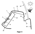
- FIG . 3 shows a further embodiment of the invention.
- the light guide plate 4 is led out of the housing 23 of the instrument cluster up to the windshield 24 of the motor vehicle in order to couple light that enters the motor vehicle through the windshield 24 as freely as possible into the light guide plate 4.
- the instrument cluster is enclosed in the dashboard and the dashboard in turn in the cabin of the motor vehicle, which is indicated in Figure 3 by the boundary lines 25, 26, 27 and 28.
- the light guide plate 4 is laid in the dashboard as a light guide system.
- the dashboard has an opening in the area in front of the windshield 24 in order to expose the light guide plate 4 embedded in the dashboard there.
- this is formed on the inside of the vehicle in front of the windshield 24 and can for example extend over the entire width of the dashboard or at least over the width of the instrument cluster.
- the coupling of the ambient light into the light guide plate 4 can be supported by suitable structures 29 attached to it in the area in front of the windshield 24 or by a coating 30 that lowers the refractive index.
- the light conduction in the light guide plate 4 is again carried out by total reflection, so that the coupled light is guided up to the LC display 1 in the instrument cluster and is then decoupled there in the manner already described for backlighting the LC display 1.
- the light guide plate 4 can be designed in several pieces.
- an analog display device with a pointer 2 the servomotor 5 driving the axis of the pointer 2
- a mask 7 covering the front of the combination instrument and the circuit board 16 are also used together with some components mounted on it.
Landscapes
- Physics & Mathematics (AREA)
- Nonlinear Science (AREA)
- Mathematical Physics (AREA)
- Chemical & Material Sciences (AREA)
- Crystallography & Structural Chemistry (AREA)
- General Physics & Mathematics (AREA)
- Optics & Photonics (AREA)
- Instrument Panels (AREA)
- Details Of Measuring Devices (AREA)
Applications Claiming Priority (2)
| Application Number | Priority Date | Filing Date | Title |
|---|---|---|---|
| DE10026892 | 2000-05-30 | ||
| DE10026892A DE10026892A1 (de) | 2000-05-30 | 2000-05-30 | Kombiinstrument für ein Kraftfahrzeug |
Publications (2)
| Publication Number | Publication Date |
|---|---|
| EP1160116A2 true EP1160116A2 (fr) | 2001-12-05 |
| EP1160116A3 EP1160116A3 (fr) | 2005-04-27 |
Family
ID=7644171
Family Applications (1)
| Application Number | Title | Priority Date | Filing Date |
|---|---|---|---|
| EP01111900A Withdrawn EP1160116A3 (fr) | 2000-05-30 | 2001-05-17 | Instrument combiné pour un véhicule automobile |
Country Status (4)
| Country | Link |
|---|---|
| US (1) | US6727962B2 (fr) |
| EP (1) | EP1160116A3 (fr) |
| BR (1) | BR0102152B1 (fr) |
| DE (1) | DE10026892A1 (fr) |
Cited By (7)
| Publication number | Priority date | Publication date | Assignee | Title |
|---|---|---|---|---|
| DE102006038175A1 (de) * | 2006-08-14 | 2008-02-21 | Johnson Controls Gmbh | Anzeigevorrichtung für ein Kraftfahrzeug |
| DE102007033568A1 (de) | 2007-07-19 | 2009-01-22 | Volkswagen Ag | Anzeigeeinrichtung für ein Fahrzeug |
| EP2072318A1 (fr) * | 2007-12-20 | 2009-06-24 | Robert Bosch GmbH | Instrument d'affichage pour un véhicule |
| DE102008013274A1 (de) | 2008-03-10 | 2009-09-17 | Volkswagen Ag | Anzeigeeinrichtung für ein Fahrzeg mit einem Display und einer transparenten Deckscheibe |
| EP2143586A1 (fr) * | 2008-07-07 | 2010-01-13 | Johnson Controls GmbH | Tableau de bord avec source de lumière naturelle |
| EP2944499A1 (fr) * | 2014-05-16 | 2015-11-18 | Johnson Controls GmbH | Dispositif d'information du conducteur |
| DE102018203860A1 (de) * | 2018-03-14 | 2019-09-19 | Faurecia Innenraum Systeme Gmbh | Beleuchtungssystem mit Lichtsammelvorrichtung |
Families Citing this family (11)
| Publication number | Priority date | Publication date | Assignee | Title |
|---|---|---|---|---|
| US20070248795A1 (en) * | 2003-06-19 | 2007-10-25 | Serigraph, Inc. | Formed Graphic Applique |
| DE10353760B4 (de) * | 2003-11-17 | 2008-10-02 | Continental Automotive Gmbh | Anzeigevorrichtung |
| US20060041503A1 (en) * | 2004-08-21 | 2006-02-23 | Blair William R | Collaborative negotiation methods, systems, and apparatuses for extended commerce |
| TWI280526B (en) * | 2005-03-18 | 2007-05-01 | Mitac Int Corp | Method of automatically switching displaying mode of navigation map |
| DE102005051965A1 (de) * | 2005-10-29 | 2007-05-03 | GM Global Technology Operations, Inc., Detroit | Kraftfahrzeug und Anzeigevorrichtung |
| US10717474B2 (en) | 2017-03-21 | 2020-07-21 | Arctic Cat Inc. | Cab and fasteners for vehicle cab |
| US11014419B2 (en) * | 2017-03-21 | 2021-05-25 | Arctic Cat Inc. | Off-road utility vehicle |
| DE102018008228B4 (de) | 2018-10-17 | 2022-01-27 | Daimler Ag | Beleuchtungsvorrichtung für einen Innenraum eines Fahrzeugs |
| US11767060B2 (en) * | 2019-04-12 | 2023-09-26 | Textron Innovations Inc. | Lightweight vehicle |
| KR20210073064A (ko) * | 2019-12-10 | 2021-06-18 | 현대자동차주식회사 | 세그먼트 lcd를 포함하는 차량용 클러스터 |
| DE102019220200A1 (de) * | 2019-12-19 | 2021-06-24 | Volkswagen Aktiengesellschaft | Leuchtelement für ein Fahrzeug und dessen Herstellung |
Citations (6)
| Publication number | Priority date | Publication date | Assignee | Title |
|---|---|---|---|---|
| US4621306A (en) * | 1984-04-04 | 1986-11-04 | Vdo Adolf Schindling Ag | Display device |
| US4747672A (en) * | 1985-04-26 | 1988-05-31 | Nippon Seiki Co., Ltd. | Light compensating liquid crystal display |
| US4789774A (en) * | 1984-06-30 | 1988-12-06 | Mannesmann Kienzle Gmbh | Electronic display device |
| US5623136A (en) * | 1994-04-16 | 1997-04-22 | Mannesmann Kienzle Gmbh | Assembly-optimized arrangement of the functional elements of a taximeter |
| EP0818701A2 (fr) * | 1996-07-09 | 1998-01-14 | Harness System Technologies Research, Ltd. | Appareil d'affichage |
| FR2760413A1 (fr) * | 1997-03-06 | 1998-09-11 | Magneti Marelli France | Tableau de bord pour vehicules automobiles comprenant une vitre externe munie d'un cadran |
Family Cites Families (2)
| Publication number | Priority date | Publication date | Assignee | Title |
|---|---|---|---|---|
| DE4140647C2 (de) * | 1991-12-10 | 1996-09-12 | Bosch Gmbh Robert | Anzeigevorrichtung mit Lichtsensor |
| EP1063561A1 (fr) * | 1999-06-11 | 2000-12-27 | Mannesmann VDO Aktiengesellschaft | Dispositif d'affichage à cristaux liquides |
-
2000
- 2000-05-30 DE DE10026892A patent/DE10026892A1/de not_active Withdrawn
-
2001
- 2001-05-17 EP EP01111900A patent/EP1160116A3/fr not_active Withdrawn
- 2001-05-21 US US09/863,076 patent/US6727962B2/en not_active Expired - Fee Related
- 2001-05-28 BR BRPI0102152-4A patent/BR0102152B1/pt not_active IP Right Cessation
Patent Citations (6)
| Publication number | Priority date | Publication date | Assignee | Title |
|---|---|---|---|---|
| US4621306A (en) * | 1984-04-04 | 1986-11-04 | Vdo Adolf Schindling Ag | Display device |
| US4789774A (en) * | 1984-06-30 | 1988-12-06 | Mannesmann Kienzle Gmbh | Electronic display device |
| US4747672A (en) * | 1985-04-26 | 1988-05-31 | Nippon Seiki Co., Ltd. | Light compensating liquid crystal display |
| US5623136A (en) * | 1994-04-16 | 1997-04-22 | Mannesmann Kienzle Gmbh | Assembly-optimized arrangement of the functional elements of a taximeter |
| EP0818701A2 (fr) * | 1996-07-09 | 1998-01-14 | Harness System Technologies Research, Ltd. | Appareil d'affichage |
| FR2760413A1 (fr) * | 1997-03-06 | 1998-09-11 | Magneti Marelli France | Tableau de bord pour vehicules automobiles comprenant une vitre externe munie d'un cadran |
Cited By (7)
| Publication number | Priority date | Publication date | Assignee | Title |
|---|---|---|---|---|
| DE102006038175A1 (de) * | 2006-08-14 | 2008-02-21 | Johnson Controls Gmbh | Anzeigevorrichtung für ein Kraftfahrzeug |
| DE102007033568A1 (de) | 2007-07-19 | 2009-01-22 | Volkswagen Ag | Anzeigeeinrichtung für ein Fahrzeug |
| EP2072318A1 (fr) * | 2007-12-20 | 2009-06-24 | Robert Bosch GmbH | Instrument d'affichage pour un véhicule |
| DE102008013274A1 (de) | 2008-03-10 | 2009-09-17 | Volkswagen Ag | Anzeigeeinrichtung für ein Fahrzeg mit einem Display und einer transparenten Deckscheibe |
| EP2143586A1 (fr) * | 2008-07-07 | 2010-01-13 | Johnson Controls GmbH | Tableau de bord avec source de lumière naturelle |
| EP2944499A1 (fr) * | 2014-05-16 | 2015-11-18 | Johnson Controls GmbH | Dispositif d'information du conducteur |
| DE102018203860A1 (de) * | 2018-03-14 | 2019-09-19 | Faurecia Innenraum Systeme Gmbh | Beleuchtungssystem mit Lichtsammelvorrichtung |
Also Published As
| Publication number | Publication date |
|---|---|
| BR0102152B1 (pt) | 2008-11-18 |
| DE10026892A1 (de) | 2001-12-06 |
| US20020008808A1 (en) | 2002-01-24 |
| EP1160116A3 (fr) | 2005-04-27 |
| US6727962B2 (en) | 2004-04-27 |
| BR0102152A (pt) | 2002-02-13 |
Similar Documents
| Publication | Publication Date | Title |
|---|---|---|
| EP1160116A2 (fr) | Instrument combiné pour un véhicule automobile | |
| DE19732119B4 (de) | Zusammengesetzte Anzeigetafel | |
| DE19848842B4 (de) | Flüssigkristallanzeige mit gekrümmtem Flüssigkristallbildschirm | |
| DE112014001955B4 (de) | Displayvorrichtung im Fahrzeug | |
| DE10212600B4 (de) | Anzeigevorrichtung für Fahrzeuge mit Lichtquellen unterschiedlicher Richtschärfe | |
| EP2762361B1 (fr) | Unité d'éclairage | |
| DE3834757C2 (de) | Skalenanordnung für ein Meßgerät zur Anzeige von an einer Skalenplatte angeordneten Markierungen | |
| DE19547375A1 (de) | Anzeigeeinrichtung | |
| EP1840626A1 (fr) | Visionneur tête haute, véhicule automobile et procédé de fonctionnement d'un visionneur tête haute | |
| EP1767986B1 (fr) | Dispositif d'affichage monochromatique retroéclairé, véhicule automobile et procédé de commande du dispositif d'affichage monochromatique | |
| DE3902956A1 (de) | Anordnung fuer eine instrumententafel oder einen instrumententafelteil, insbesondere fuer kraftfahrzeuge | |
| EP1106419B1 (fr) | Appareil de commande à éléments de commande lumineux | |
| DE19644804B4 (de) | Elektrolumineszenz-Anzeigevorrichtung für ein Fahrzeug | |
| DE19646042A1 (de) | Beleuchtungseinrichtung für Fahrzeuge | |
| WO2005116663A1 (fr) | Instrument indicateur pour vehicule a moteur | |
| DE10144615B4 (de) | Anzeigevorrichtung | |
| DE19545604C2 (de) | Scheibenwischanlage für Heckscheiben mit einem in die Bremsleuchte integrierten Feuchtesensor | |
| DE112019001649B4 (de) | Elektrische vorrichtung für ein fahrzeugtrittbrett | |
| DE2902745A1 (de) | Ueber lichtleiter beleuchtete kraftfahrzeuginstrumente | |
| DE19627212C2 (de) | Betätigungseinheit für eine Fahrzeugkomponente, insbesondere eine Fahrzeug-Klimaanlage | |
| DE3113773C2 (fr) | ||
| DE3032344A1 (de) | Fluessigkeitskristallanzeigen | |
| DE4121248B4 (de) | Beleuchtbares Zeigerinstrument | |
| DE3510532C2 (fr) | ||
| DE102011016432A1 (de) | Frontscheibe für ein Kraftfahrzeug |
Legal Events
| Date | Code | Title | Description |
|---|---|---|---|
| PUAI | Public reference made under article 153(3) epc to a published international application that has entered the european phase |
Free format text: ORIGINAL CODE: 0009012 |
|
| AK | Designated contracting states |
Kind code of ref document: A2 Designated state(s): AT BE CH CY DE DK ES FI FR GB GR IE IT LI LU MC NL PT SE TR |
|
| AX | Request for extension of the european patent |
Free format text: AL;LT;LV;MK;RO;SI |
|
| RAP1 | Party data changed (applicant data changed or rights of an application transferred) |
Owner name: SIEMENS AKTIENGESELLSCHAFT |
|
| PUAL | Search report despatched |
Free format text: ORIGINAL CODE: 0009013 |
|
| AK | Designated contracting states |
Kind code of ref document: A3 Designated state(s): AT BE CH CY DE DK ES FI FR GB GR IE IT LI LU MC NL PT SE TR |
|
| AX | Request for extension of the european patent |
Extension state: AL LT LV MK RO SI |
|
| RIC1 | Information provided on ipc code assigned before grant |
Ipc: 7B 60Q 3/04 B Ipc: 7B 60K 37/02 A |
|
| 17P | Request for examination filed |
Effective date: 20051010 |
|
| AKX | Designation fees paid |
Designated state(s): AT BE CH CY DE DK ES FI FR GB GR IE IT LI LU MC NL PT SE TR |
|
| RAP1 | Party data changed (applicant data changed or rights of an application transferred) |
Owner name: CONTINENTAL AUTOMOTIVE GMBH |
|
| STAA | Information on the status of an ep patent application or granted ep patent |
Free format text: STATUS: THE APPLICATION IS DEEMED TO BE WITHDRAWN |
|
| 18D | Application deemed to be withdrawn |
Effective date: 20091201 |