EP1158796A1 - Méthode et dispositif pour la décodage d'un train de données vidéo en modes de reproduction spéciale - Google Patents
Méthode et dispositif pour la décodage d'un train de données vidéo en modes de reproduction spéciale Download PDFInfo
- Publication number
- EP1158796A1 EP1158796A1 EP01110699A EP01110699A EP1158796A1 EP 1158796 A1 EP1158796 A1 EP 1158796A1 EP 01110699 A EP01110699 A EP 01110699A EP 01110699 A EP01110699 A EP 01110699A EP 1158796 A1 EP1158796 A1 EP 1158796A1
- Authority
- EP
- European Patent Office
- Prior art keywords
- picture
- pictures
- decoding
- reconstruction
- buffer
- Prior art date
- Legal status (The legal status is an assumption and is not a legal conclusion. Google has not performed a legal analysis and makes no representation as to the accuracy of the status listed.)
- Granted
Links
Images


Classifications
-
- H—ELECTRICITY
- H04—ELECTRIC COMMUNICATION TECHNIQUE
- H04N—PICTORIAL COMMUNICATION, e.g. TELEVISION
- H04N5/00—Details of television systems
- H04N5/76—Television signal recording
- H04N5/78—Television signal recording using magnetic recording
- H04N5/782—Television signal recording using magnetic recording on tape
- H04N5/783—Adaptations for reproducing at a rate different from the recording rate
-
- H—ELECTRICITY
- H04—ELECTRIC COMMUNICATION TECHNIQUE
- H04N—PICTORIAL COMMUNICATION, e.g. TELEVISION
- H04N5/00—Details of television systems
- H04N5/76—Television signal recording
- H04N5/91—Television signal processing therefor
- H04N5/92—Transformation of the television signal for recording, e.g. modulation, frequency changing; Inverse transformation for playback
-
- G—PHYSICS
- G06—COMPUTING; CALCULATING OR COUNTING
- G06T—IMAGE DATA PROCESSING OR GENERATION, IN GENERAL
- G06T9/00—Image coding
- G06T9/007—Transform coding, e.g. discrete cosine transform
-
- H—ELECTRICITY
- H04—ELECTRIC COMMUNICATION TECHNIQUE
- H04N—PICTORIAL COMMUNICATION, e.g. TELEVISION
- H04N21/00—Selective content distribution, e.g. interactive television or video on demand [VOD]
- H04N21/40—Client devices specifically adapted for the reception of or interaction with content, e.g. set-top-box [STB]; Operations thereof
-
- H—ELECTRICITY
- H04—ELECTRIC COMMUNICATION TECHNIQUE
- H04N—PICTORIAL COMMUNICATION, e.g. TELEVISION
- H04N9/00—Details of colour television systems
- H04N9/79—Processing of colour television signals in connection with recording
- H04N9/80—Transformation of the television signal for recording, e.g. modulation, frequency changing; Inverse transformation for playback
- H04N9/804—Transformation of the television signal for recording, e.g. modulation, frequency changing; Inverse transformation for playback involving pulse code modulation of the colour picture signal components
- H04N9/8042—Transformation of the television signal for recording, e.g. modulation, frequency changing; Inverse transformation for playback involving pulse code modulation of the colour picture signal components involving data reduction
- H04N9/8045—Transformation of the television signal for recording, e.g. modulation, frequency changing; Inverse transformation for playback involving pulse code modulation of the colour picture signal components involving data reduction using predictive coding
-
- H—ELECTRICITY
- H04—ELECTRIC COMMUNICATION TECHNIQUE
- H04N—PICTORIAL COMMUNICATION, e.g. TELEVISION
- H04N5/00—Details of television systems
- H04N5/76—Television signal recording
- H04N5/78—Television signal recording using magnetic recording
- H04N5/781—Television signal recording using magnetic recording on disks or drums
Definitions
- an MPEG video stream is stored in a storage device (for example a Hard Disk Drive ⁇ HDD- integrated into a digital video decoder set top box) and can be read back and presented with the use of an MPEG decoder, the possibility of trickmode play such as reverse playback at different speeds is naturally expected by the user.
- a storage device for example a Hard Disk Drive ⁇ HDD- integrated into a digital video decoder set top box
- one solution consists in decoding all pictures corresponding a group of pictures (generally 12 pictures) before displaying any picture from this group of pictures.
- the last picture (in forward direction display order) of such a group may indeed depend on the first picture of the group, which is an intra type picture. Only some of these decoded pictures may be displayed, depending on the playback speed.
- Usual video decoders carry out one picture decoding per display period (e.g. 40 ms). This is not adapted to trickmode playback.
- the object of the invention is a method for decoding compressed video pictures in a video decoding device comprising a random access source of coded video pictures, a video decoder and a plurality of reconstruction buffers for storing decoded pictures, characterized by the steps of:
- the method moreover comprises the following steps:
- the decoding is thus controlled by the display process: it is this process which unlocks access to reconstruction buffers and thus controls when the next picture is decoded.
- the step of establishing an order for decoding pictures comprises the steps of:
- the compressed video stream comprises pictures in the order of decoding
- the method further comprises the steps of determining for a bi-directional picture a nearest and a farthest predictor, where said nearest predictor is the picture appearing in the stream closest to said bi-directional picture, said farthest predictor being decoded prior to said nearest predictor.
- the step of determining an order of decoding pictures comprises the steps of:
- the method moreover comprises the step of selecting a reconstruction buffer among available reconstruction buffers for storage of a decoded picture, said selection being carried out so as to select the available reconstruction buffer in which no decoded picture to be displayed has been stored for the longest time.
- the method further comprises the step of attributing a counter to each reconstruction buffer, of incrementing each counter every time a picture is displayed, of resetting a counter when a picture of its associated buffer is displayed and of attributing the buffer with the highest counter value to a picture to be decoded.
- the method is carried out using only three reconstruction buffers, but is not necessarily limited to that number.
- the method further comprises the steps of verifying prior to the decoding of a picture, whether said picture is already present in one of the reconstruction buffers, and of avoiding a second decoding of said picture in this case.
- Another object of the invention is a video decoding device characterized by
- the random access source may also be an intermediate storage area, connected to a sequential source.
- the inventive method and device enable playback of a recorded video stream in reverse direction at different speeds using only three reconstruction buffers.
- the inventive method determines and decodes, using a recursive process, the predictor pictures of a picture to be displayed.
- predetermined trickmode information describing the recorded stream is used to determine predictor pictures.
- This trickmode information may take the form of a linked list of picture descriptors describing their type and the location of relevant data in the recorded stream.
- a specific buffer allocation mechanism is used in order to determine which reconstruction buffer is to be used for which picture.
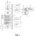
- the digital television receiver/decoder 1 of figure 1 comprises a Forward Error Correction circuit 2 fed by a tuner and analog/digital converter (not shown).
- the corrected digital signal is fed to a Transport Stream demultiplexer and filter 4.
- This demultiplexer and filter 4 is connected to the central communication bus 11 of the receiver 1. Its role is to select certain Transport Stream (TS) packets in the incoming data stream and to dispatch them to different applications of the receiver. For that purpose, it comprises filters programmed by a microprocessor 10.
- TS Transport Stream
- the receiver For the purpose of recording MPEG streams, the receiver comprises a hard disk drive 12 linked to the bus 11 through an interface 13, for example and EIDE interface.
- a memory 5 comprises several buffers and areas used to store and retrieve information from the hard disk.
- the memory 5 comprises circular buffers 15 to 23.
- a Write FIFO 15 is used to store, in order of arrival from demultiplexer and filter 4, TS packets for recording on the hard disk 12.
- a Read FIFO 16 is used to store TS packets read from the hard disk. FIFOs 15 and 16 are used to record or read a substream of the received data stream, disregarding the nature of the content of the TS packets. For recording, all TS packets corresponding to programmed criteria are filtered and written to Write FIFO 15 before transfer to hard disk 12. This mode is called the Transport Stream level recording mode, and will be the mode used in the rest of this description.
- FIFOs 18 to 23 are used for that purpose.
- Memory 5 also holds a trickmode buffer 17. This buffer is used by the Stream Parser 3 and the microprocessor during recording to generate trickmode information, which is then recorded on the hard disk. This buffer is also used during reproduction to store trickmode information read from the hard disk.
- the receiver 1 also comprises respective audio and video decoders 8 and 9, connected to the central bus 11 either through a Transport Stream demultiplexer and a PES parser 6, or directly through PES parser 6.
- the TS layer may or may not have been previously removed.
- Reference 14 indicates the video processing circuitry required to generate displayable analog video signals.
- Compressed data destined to the video decoder 9 is stored in an input bit buffer 25, from where it is read as appropriate by the decoder 9.
- Reconstructed pictures are stored in a reconstruction memory 26, which is accessed by the decoder for both reading and writing.
- the reconstruction memory according to the invention has three buffers (A, B, C), each corresponding to one decoded picture.
- Receiver 1 also comprises a reprogrammable non-volatile memory 24, which holds the receiver's operating system, device drivers and other software modules.
- the receiver's software is executed by the microprocessor.
- trickmode information contains for each video access unit stored on the disk and in the order of recording, the type of picture (I, P or B) and the location of the relevant picture, group of picture and sequence information on the hard disk required to decode a picture.
- Trickmode information is segmented into three different types of tables: A time index table, a video unit description table and several video description units (VDUs), each VDU describing the content of a certain number of successive groups of pictures.
- VDUs video description units
- trickmode information is described in the European patent application entitled “Method and device for decoding a digital video stream in a digital video system using dummy header insertion” filed in the name of THOMSON multimedia on April 5, 2000.
- FIG. 2 is a diagram of the software model of the receiver 1 according to the present embodiment. It comprises the following elements:
- the picture display is a synchronous process. For a 50Hz system, the Display Manager checks every 40ms which picture is to be displayed. In other words, it identifies the reconstruction buffer containing the picture to be displayed.
- the display process is the slowest process in the chain. All other processes will follow the rhythm imposed by the display.
- the decoding process is asynchronous and can be very fast, when a picture to be displayed is decoded, its reconstruction buffer is locked to avoid any overwriting by subsequent pictures before it has been actually displayed. Only the Display Manager is allowed to unlock a buffer when the picture is displayed and when a new picture reconstruction can start in the same buffer.
- the Video Decoding Manager waits for the Display Manager to display pictures and release buffers, in order to decode new pictures as requested by the Overall Trickmode Control.
- the Overall Trickmode Control and coded picture supply by the Stream Access Manager are synchronized.
- the Overall Trickmode Control requests the transmission of a new picture when necessary and waits for the transmission to be completed before issuing another request. The completion of the transmission is notified to the Overall Trickmode Control process by the Stream Access Manager.
- the Stream Access Manager and the Overall Control wait for the video decoder to retrieve data from the bit buffer, and the video decoder, under the control of the Video Decoding Manager, waits for the Display Manager to release buffers. The whole system will finally follow the display rhythm.
- FIG. 3 is an overview of the overall video process for a given picture. Several such processes may run in parallel at different stages of execution.
- a first operation consists in identifying the next picture to be displayed. This of course depends on the type of trickmode. Once this picture is determined, it has to be decoded. This operation may involve the recursive decoding of other pictures. It also depends on the availability of one or more free reconstruction buffers.
- the last operation consists in displaying the decoded picture.
- the trickmode information is a data structure comprising linked items. It is made of Picture descriptors linked with each other according to their order in the stream. The reader is reminded that the stream as received (and in this case as recorded) contains pictures in decoding order, not display order. Each Picture descriptor gives details about a picture in the MPEG coded stream as well as enough information to locate the compressed material of the picture on the storage unit. Each picture in the stream is identified with a particular Picture ID. In figures 3 and 4, "N" is such a picture ID and a function 'Next(N)' returns a picture ID. The Next(N) function's processing is based on an analysis of the trickmode Information, given the type of trickmode to be displayed.
- Next(N) In forward mode, Next(N) returns the ID of following picture to be displayed according to normal display order (i.e. in respect to the temporal reference). In backward mode, Next(N) returns the ID of the previous picture according to normal display order.
- the Next(N) function is implemented by the Overall Trickmode Control module which, knowing N, uses the trickmode tables defined in the already mentioned patent application to access all data required to decode a picture.
- Slow motion trickmodes forward or backward are under the control of the Display Manager as this trickmode simply implies a display rate lower than one picture per 40ms.
- Figure 4 illustrates the DecodePicture command principle.
- the reconstruction buffers' current state is represented to the left of the diagram.
- the buffers each contain certain pictures (X, Y, Z).
- the DecodePicture process ensures that if applied to a picture N, one of the buffers will in the end contain this requested picture, whatever the content of the other two buffers.
- an MPEG picture may depend on other pictures and its decoding may require the availability of already reconstructed pictures.
- An MPEG coded stream always contains a number of entry points under the form of Intra pictures. None of the pictures following such an entry point may depend on pictures preceding the entry point.
- the DVB standard specifies that these entry points shall occur at least every 0.5 s. Open Groups of Pictures are a particular case.
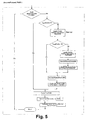
- the DecodePicture command is implemented in a recursive way as illustrated by the flowchart of figure 5. If the decoding of a picture requires the presence of one or two previously decoded pictures, these latter pictures are decoded first.
- the target picture does not yet exist in the reconstruction buffers, then it needs to be decoded. If the picture identified by PicID is of "P" or "B" type, then its decoding may require the presence of forward and backward predictors. This information is available in the trickmode tables.
- NearestlD is a Forward Predictor in the sense that the NearestID picture is located, in the time scale and display order, before the picture identified by PicID.
- the DecodePicture command is recursively repeated for these pictures.
- Preceding the reconstruction of a B Picture up to two predictors may have to be decoded, unless already decoded and present in the reconstruction buffer.
- FarthestlD is decoded first, followed by NearestID. Since NearestID may also depend on FarthestID, the latter is decoded first: the process is thus optimized and a double decoding of the picture corresponding to FarthestlD is avoided. For example, if a B picture is predicted from two P pictures, the second P picture in time depends on the first P picture.
- Decoding an Intra picture requires only one free buffer, since no predictor is required.
- Decoding a Predictive picture requires one predictor: one or two buffers may have to be used, depending on whether the decoded predictor of the Predictive picture is already present in another buffer or not, i.e. whether a recursive decoding has to be carried out or not.
- one of the three buffers one contains the picture currently displayed.
- two buffers are available for decoding further pictures ⁇ supposing they do not contain a picture to be displayed after the current picture ⁇ and thus any I or P picture may be decoded without disturbing the display of the current picture.
- B pictures on the other hand require two predictors.
- one of the two predictors ('Nearest Predictor') will depend on the other ('Farthest Predictor').
- By decoding first the farthest predictor, followed by the nearest predictor only two buffers are required to decode both predictors.
- both predictors may be independent, but since these predictors comprise an I picture from the current Group of Pictures and a P (or I) picture from the previous Group of Pictures, only two buffers are required as along as the P or I picture of the previous Group of Pictures is decoded first.
- an available reconstruction buffer must be chosen to receive the new picture to be decoded and displayed. In some cases, there may be no choice, such as in the case of decoding a B picture: all three buffers need to be used, one for the forward predictor, one for the backward predictor and one for the B picture itself.
- the allocation of the three reconstruction buffers between display and decoding is critical for the performance of the overall system. Indeed, when the proper buffer is not chosen, an additional delay may be introduced for decoding a given picture. Depending on the processing power of the video decoder, it may then happen that a picture is not fully decoded before it is to be displayed.
- the buffer to be chosen for a picture to be displayed is the free buffer that was released by the display process the longest time ago.
- a counter is associated with each buffer model element.
- the counter of this buffer is reset and counters of other buffers are incremented.
- the buffer allocated to a new picture is the buffer that has the highest counter value.
- Figure 6 is a flowchart of the buffer allocation process. It consists in cycling through all buffers, discarding those locked because containing a predictor, and selecting among the unlocked ones (if any) the one having the greatest counter value.
- Figure 7 indicates the content of each of the buffers A, B and C.
- the 'Frame Period' column counts the 40ms display periods (whatever its thickness on the figure).
- the period '0' corresponds to the display period of P11.
- the 'Displ. Picture' column indicates which picture is displayed during the associated frame period.
- the 'Decoding per Fr. period' indicates the number of pictures decoded during a given 40ms period. Grey areas indicate when the content of a given buffer is displayed.
- a picture may start to be displayed before it is fully decoded. For example, if it is indicated that a picture B"1 is decoded while at the same time being displayed, this means that the display starts at the earliest 20ms after the decoding of the picture.
- Figure 7 lists in the order of decoding all the pictures (whether to be displayed or not) determined by the recursive process described above.
- P11 is then to be displayed. Since it is already present in buffer B, no new decoding has to be carried out for this picture and it can be immediately displayed.
Landscapes
- Engineering & Computer Science (AREA)
- Multimedia (AREA)
- Signal Processing (AREA)
- Physics & Mathematics (AREA)
- General Physics & Mathematics (AREA)
- Discrete Mathematics (AREA)
- Theoretical Computer Science (AREA)
- Compression Or Coding Systems Of Tv Signals (AREA)
- Television Signal Processing For Recording (AREA)
- Signal Processing For Digital Recording And Reproducing (AREA)
Priority Applications (1)
| Application Number | Priority Date | Filing Date | Title |
|---|---|---|---|
| EP01110699A EP1158796B1 (fr) | 2000-05-19 | 2001-05-02 | Méthode et dispositif pour la décodage d'un train de données vidéo en modes de reproduction spéciale |
Applications Claiming Priority (3)
| Application Number | Priority Date | Filing Date | Title |
|---|---|---|---|
| EP00401381A EP1156674A1 (fr) | 2000-05-19 | 2000-05-19 | Méthode et dispositif pour la décodage d'un train de données vidéo en modes de reproduction spéciale |
| EP00401381 | 2000-05-19 | ||
| EP01110699A EP1158796B1 (fr) | 2000-05-19 | 2001-05-02 | Méthode et dispositif pour la décodage d'un train de données vidéo en modes de reproduction spéciale |
Publications (2)
| Publication Number | Publication Date |
|---|---|
| EP1158796A1 true EP1158796A1 (fr) | 2001-11-28 |
| EP1158796B1 EP1158796B1 (fr) | 2005-01-05 |
Family
ID=8173691
Family Applications (2)
| Application Number | Title | Priority Date | Filing Date |
|---|---|---|---|
| EP00401381A Withdrawn EP1156674A1 (fr) | 2000-05-19 | 2000-05-19 | Méthode et dispositif pour la décodage d'un train de données vidéo en modes de reproduction spéciale |
| EP01110699A Expired - Lifetime EP1158796B1 (fr) | 2000-05-19 | 2001-05-02 | Méthode et dispositif pour la décodage d'un train de données vidéo en modes de reproduction spéciale |
Family Applications Before (1)
| Application Number | Title | Priority Date | Filing Date |
|---|---|---|---|
| EP00401381A Withdrawn EP1156674A1 (fr) | 2000-05-19 | 2000-05-19 | Méthode et dispositif pour la décodage d'un train de données vidéo en modes de reproduction spéciale |
Country Status (16)
| Country | Link |
|---|---|
| US (1) | US7130526B2 (fr) |
| EP (2) | EP1156674A1 (fr) |
| JP (1) | JP5106722B2 (fr) |
| KR (1) | KR100788869B1 (fr) |
| CN (1) | CN1226873C (fr) |
| AT (1) | ATE286643T1 (fr) |
| AU (1) | AU777957B2 (fr) |
| BR (1) | BR0102043A (fr) |
| DE (1) | DE60108199T2 (fr) |
| ES (1) | ES2234729T3 (fr) |
| HK (1) | HK1038861B (fr) |
| HU (1) | HUP0101843A3 (fr) |
| MX (1) | MXPA01004843A (fr) |
| MY (1) | MY127087A (fr) |
| TW (1) | TW530494B (fr) |
| ZA (1) | ZA200103672B (fr) |
Cited By (1)
| Publication number | Priority date | Publication date | Assignee | Title |
|---|---|---|---|---|
| EP1635566A3 (fr) * | 2004-08-18 | 2006-05-03 | Sony Corporation | Appareil de commande de décodage, procédé de commande de décodage, programme d'ordinateur, et support d'enregistrement |
Families Citing this family (29)
| Publication number | Priority date | Publication date | Assignee | Title |
|---|---|---|---|---|
| US7177522B2 (en) * | 2000-10-10 | 2007-02-13 | Broadcom Corporation | System and method for personal video recording |
| US8559797B2 (en) * | 2000-10-10 | 2013-10-15 | Broadcom Corporation | System and method for personal video recording |
| US6771274B2 (en) | 2002-03-27 | 2004-08-03 | Sony Corporation | Graphics and video integration with alpha and video blending |
| US6847780B2 (en) | 2002-03-28 | 2005-01-25 | Sony Corporation | Trick-mode stream creation for personal video recording functions |
| PT2278816E (pt) | 2002-07-11 | 2013-05-10 | Panasonic Corp | Gestão de memória tampão pós-descodificador para um fluxo de bits de mpeg de h.264-svc |
| WO2004012037A2 (fr) * | 2002-07-26 | 2004-02-05 | Prediwave Corporation | Traitement en mode d'enrichissement mpeg a la volee |
| US7577204B2 (en) * | 2002-11-15 | 2009-08-18 | Broadcom Corporation | Hits stream rewind |
| US20040258160A1 (en) * | 2003-06-20 | 2004-12-23 | Sandeep Bhatia | System, method, and apparatus for decoupling video decoder and display engine |
| JP2005017896A (ja) * | 2003-06-27 | 2005-01-20 | Canon Inc | 光走査装置及びそれを用いた画像形成装置 |
| US8077778B2 (en) * | 2003-10-31 | 2011-12-13 | Broadcom Corporation | Video display and decode utilizing off-chip processor and DRAM |
| KR100716970B1 (ko) * | 2003-12-08 | 2007-05-10 | 삼성전자주식회사 | 디지털 저장 미디어의 트릭 재생 방법 및 그에 적합한디지털 저장 미디어 구동기 |
| US20050169376A1 (en) * | 2004-01-30 | 2005-08-04 | Pai Ramadas L. | Motion vector address computer error detection |
| US8233781B2 (en) * | 2004-09-01 | 2012-07-31 | Panasonic Corporation | Image reproduction method and image reproduction apparatus |
| EP1633128A1 (fr) * | 2004-09-02 | 2006-03-08 | Deutsche Thomson-Brandt Gmbh | Procédé et dispositif pour décoder des groupes d'images codés d'une séquence vidéo et présenter cette séquence vidéo et ces groupes d'images dans un ordre chronologique inversé |
| TW200611256A (en) * | 2004-09-29 | 2006-04-01 | Quanta Storage Inc | Disk device with multimedia video interface |
| US7885338B1 (en) * | 2005-04-25 | 2011-02-08 | Apple Inc. | Decoding interdependent frames of a video for display |
| KR100765787B1 (ko) * | 2006-06-15 | 2007-10-12 | 삼성전자주식회사 | 압축 부호화된 영상 데이터 스트림의 재생 방법 및 그 장치 |
| KR100841317B1 (ko) * | 2006-07-14 | 2008-06-26 | 엘지전자 주식회사 | 텔레비젼의 시스템 구동과 관련된 소프트웨어를 송수신하는 방법 및 그 장치 |
| JP4902854B2 (ja) * | 2006-09-12 | 2012-03-21 | パナソニック株式会社 | 動画像復号化装置、動画像復号化方法、動画像復号化プログラム、動画像符号化装置、動画像符号化方法、動画像符号化プログラム、及び動画像符号化復号化装置 |
| US8411734B2 (en) * | 2007-02-06 | 2013-04-02 | Microsoft Corporation | Scalable multi-thread video decoding |
| US8265144B2 (en) * | 2007-06-30 | 2012-09-11 | Microsoft Corporation | Innovations in video decoder implementations |
| US9648325B2 (en) * | 2007-06-30 | 2017-05-09 | Microsoft Technology Licensing, Llc | Video decoding implementations for a graphics processing unit |
| US8885729B2 (en) | 2010-12-13 | 2014-11-11 | Microsoft Corporation | Low-latency video decoding |
| CN102572295B (zh) * | 2010-12-21 | 2014-04-02 | 新奥特(北京)视频技术有限公司 | 一种特效图调度方法 |
| US9706214B2 (en) | 2010-12-24 | 2017-07-11 | Microsoft Technology Licensing, Llc | Image and video decoding implementations |
| SG10201408609SA (en) | 2011-06-30 | 2015-02-27 | Microsoft Technology Licensing Llc | Reducing latency in video encoding and decoding |
| US8731067B2 (en) | 2011-08-31 | 2014-05-20 | Microsoft Corporation | Memory management for video decoding |
| US9819949B2 (en) | 2011-12-16 | 2017-11-14 | Microsoft Technology Licensing, Llc | Hardware-accelerated decoding of scalable video bitstreams |
| EP2635025B1 (fr) * | 2012-02-29 | 2015-04-08 | Advanced Digital Broadcast S.A. | Procédé de traitement vidéo et appareil vidéo mettant en oeuvre le procédé |
Citations (1)
| Publication number | Priority date | Publication date | Assignee | Title |
|---|---|---|---|---|
| EP0725399A2 (fr) * | 1995-01-31 | 1996-08-07 | Sony Corporation | Décodage et reproduction inverse de signaux codés |
Family Cites Families (15)
| Publication number | Priority date | Publication date | Assignee | Title |
|---|---|---|---|---|
| JP3128393B2 (ja) * | 1993-05-31 | 2001-01-29 | 三洋電機株式会社 | 圧縮動画像再生装置 |
| JPH0795536A (ja) * | 1993-05-31 | 1995-04-07 | Toshiba Corp | 動画像逆再生装置及び方法 |
| JP3607315B2 (ja) * | 1994-03-23 | 2005-01-05 | パイオニア株式会社 | 動画像復号化装置 |
| US5892882A (en) * | 1994-03-23 | 1999-04-06 | Pioneer Electronic Corporation | Moving picture decoding device having a compressed picture data memory |
| JP3250588B2 (ja) * | 1994-07-12 | 2002-01-28 | ソニー株式会社 | データ再生装置 |
| US6009231A (en) * | 1994-09-05 | 1999-12-28 | Sony Corporation | Reproduction of information using a ring buffer with read and write pointers separated from each other by substantially half of the total ring buffer capacity |
| JPH08130715A (ja) * | 1994-10-31 | 1996-05-21 | Sony Corp | 画像再生装置 |
| JPH08214265A (ja) * | 1995-01-31 | 1996-08-20 | Sony Corp | 符号化データの再生方法および再生装置 |
| JP3484834B2 (ja) * | 1995-07-28 | 2004-01-06 | ソニー株式会社 | データ符号化/復号化方法および装置 |
| GB9703470D0 (en) * | 1997-02-19 | 1997-04-09 | Thomson Consumer Electronics | Trick play reproduction of MPEG encoded signals |
| US6453114B2 (en) * | 1997-02-18 | 2002-09-17 | Thomson Licensing Sa | Random picture decoding |
| JP3860319B2 (ja) * | 1998-01-09 | 2006-12-20 | 株式会社東芝 | 画像再生方法及び装置 |
| JP3132479B2 (ja) * | 1998-08-28 | 2001-02-05 | 日本電気株式会社 | 圧縮ストリーム復号化方法および圧縮ストリーム復号化装置 |
| JP3130876B2 (ja) * | 1998-09-08 | 2001-01-31 | 日本電気アイシーマイコンシステム株式会社 | 画像再生装置及び画像再生方法 |
| US6751400B1 (en) * | 1998-09-17 | 2004-06-15 | Sony Corporation | Reproducing method and apparatus |
-
2000
- 2000-05-19 EP EP00401381A patent/EP1156674A1/fr not_active Withdrawn
-
2001
- 2001-05-02 AT AT01110699T patent/ATE286643T1/de not_active IP Right Cessation
- 2001-05-02 EP EP01110699A patent/EP1158796B1/fr not_active Expired - Lifetime
- 2001-05-02 ES ES01110699T patent/ES2234729T3/es not_active Expired - Lifetime
- 2001-05-02 DE DE60108199T patent/DE60108199T2/de not_active Expired - Lifetime
- 2001-05-04 US US09/849,570 patent/US7130526B2/en not_active Expired - Fee Related
- 2001-05-04 HU HU0101843A patent/HUP0101843A3/hu unknown
- 2001-05-04 TW TW090110676A patent/TW530494B/zh not_active IP Right Cessation
- 2001-05-07 ZA ZA200103672A patent/ZA200103672B/xx unknown
- 2001-05-09 KR KR1020010025198A patent/KR100788869B1/ko not_active IP Right Cessation
- 2001-05-14 MX MXPA01004843A patent/MXPA01004843A/es active IP Right Grant
- 2001-05-15 AU AU43887/01A patent/AU777957B2/en not_active Ceased
- 2001-05-16 MY MYPI20012293 patent/MY127087A/en unknown
- 2001-05-17 JP JP2001147845A patent/JP5106722B2/ja not_active Expired - Fee Related
- 2001-05-18 BR BR0102043-9A patent/BR0102043A/pt not_active IP Right Cessation
- 2001-05-21 CN CNB011169907A patent/CN1226873C/zh not_active Expired - Fee Related
-
2002
- 2002-01-17 HK HK02100365.5A patent/HK1038861B/zh not_active IP Right Cessation
Patent Citations (1)
| Publication number | Priority date | Publication date | Assignee | Title |
|---|---|---|---|---|
| EP0725399A2 (fr) * | 1995-01-31 | 1996-08-07 | Sony Corporation | Décodage et reproduction inverse de signaux codés |
Cited By (2)
| Publication number | Priority date | Publication date | Assignee | Title |
|---|---|---|---|---|
| EP1635566A3 (fr) * | 2004-08-18 | 2006-05-03 | Sony Corporation | Appareil de commande de décodage, procédé de commande de décodage, programme d'ordinateur, et support d'enregistrement |
| US8041194B2 (en) | 2004-08-18 | 2011-10-18 | Sony Corporation | Decode control apparatus, decode control method, computer program, and recording medium |
Also Published As
| Publication number | Publication date |
|---|---|
| KR100788869B1 (ko) | 2007-12-27 |
| ZA200103672B (en) | 2001-11-15 |
| HK1038861A1 (en) | 2002-03-28 |
| EP1158796B1 (fr) | 2005-01-05 |
| AU4388701A (en) | 2001-11-22 |
| MY127087A (en) | 2006-11-30 |
| HK1038861B (zh) | 2006-01-20 |
| EP1156674A1 (fr) | 2001-11-21 |
| BR0102043A (pt) | 2001-12-18 |
| TW530494B (en) | 2003-05-01 |
| KR20010106226A (ko) | 2001-11-29 |
| CN1325234A (zh) | 2001-12-05 |
| HUP0101843A2 (en) | 2002-06-29 |
| ATE286643T1 (de) | 2005-01-15 |
| DE60108199T2 (de) | 2006-01-26 |
| HUP0101843A3 (en) | 2003-08-28 |
| JP2002027409A (ja) | 2002-01-25 |
| JP5106722B2 (ja) | 2012-12-26 |
| US20020001458A1 (en) | 2002-01-03 |
| ES2234729T3 (es) | 2005-07-01 |
| MXPA01004843A (es) | 2004-10-29 |
| US7130526B2 (en) | 2006-10-31 |
| AU777957B2 (en) | 2004-11-04 |
| DE60108199D1 (de) | 2005-02-10 |
| CN1226873C (zh) | 2005-11-09 |
Similar Documents
| Publication | Publication Date | Title |
|---|---|---|
| EP1158796B1 (fr) | Méthode et dispositif pour la décodage d'un train de données vidéo en modes de reproduction spéciale | |
| CN102014261B (zh) | 存储数据的方法和设备以及记录电视节目的方法和设备 | |
| JP4867235B2 (ja) | 情報処理装置および情報処理方法、記録媒体、並びに、プログラム | |
| JPH06208493A (ja) | 情報信号記憶検索装置 | |
| EP0594241B1 (fr) | Appareil de mémorisation d'un signal d'information dans une mémoire et de recouvrement du signal d'information de la mémoire en question | |
| EP2405435A2 (fr) | Procédé et appareil pour recevoir, stocker et présenter une programmation sans indexation avant le stockage | |
| WO1996033579A1 (fr) | Unite video numerique domestique a memoire d'archivage et memoire a acces etendu combinees | |
| US6775463B1 (en) | Video data receiver and method of displaying said data | |
| US7430361B2 (en) | Process and device for decoding MPEG pictures and for displaying them in rewind mode, video driver circuit and decoder box incorporating such a device | |
| JP4526145B2 (ja) | Mpegビデオ復号器およびmpegビデオ復号方法 | |
| JP4325194B2 (ja) | 記憶媒体へのアクセスを管理する装置及び方法 | |
| JPH0993540A (ja) | Vodシステムにおける特殊再生方式 | |
| US20060050792A1 (en) | Method and device for processing digital images | |
| MXPA01006544A (en) | Method for storing digital audio and video dataflow, storage device and receiver for implementing said method | |
| JP2003274364A (ja) | 記録再生装置 | |
| AU2015215886A1 (en) | Improvements in receivers for television signals | |
| MXPA00010944A (en) | Method for storing compressed digital audio and video |
Legal Events
| Date | Code | Title | Description |
|---|---|---|---|
| PUAI | Public reference made under article 153(3) epc to a published international application that has entered the european phase |
Free format text: ORIGINAL CODE: 0009012 |
|
| AK | Designated contracting states |
Kind code of ref document: A1 Designated state(s): AT BE CH CY DE DK ES FI FR GB GR IE IT LI LU MC NL PT SE TR |
|
| AX | Request for extension of the european patent |
Free format text: AL;LT;LV;MK;RO;SI |
|
| 17P | Request for examination filed |
Effective date: 20020514 |
|
| AKX | Designation fees paid |
Free format text: AT BE CH CY DE DK ES FI FR GB GR IE IT LI LU MC NL PT SE TR |
|
| 17Q | First examination report despatched |
Effective date: 20030710 |
|
| GRAP | Despatch of communication of intention to grant a patent |
Free format text: ORIGINAL CODE: EPIDOSNIGR1 |
|
| GRAS | Grant fee paid |
Free format text: ORIGINAL CODE: EPIDOSNIGR3 |
|
| GRAA | (expected) grant |
Free format text: ORIGINAL CODE: 0009210 |
|
| AK | Designated contracting states |
Kind code of ref document: B1 Designated state(s): AT BE CH CY DE DK ES FI FR GB GR IE IT LI LU MC NL PT SE TR |
|
| PG25 | Lapsed in a contracting state [announced via postgrant information from national office to epo] |
Ref country code: NL Free format text: LAPSE BECAUSE OF FAILURE TO SUBMIT A TRANSLATION OF THE DESCRIPTION OR TO PAY THE FEE WITHIN THE PRESCRIBED TIME-LIMIT Effective date: 20050105 Ref country code: LI Free format text: LAPSE BECAUSE OF FAILURE TO SUBMIT A TRANSLATION OF THE DESCRIPTION OR TO PAY THE FEE WITHIN THE PRESCRIBED TIME-LIMIT Effective date: 20050105 Ref country code: CH Free format text: LAPSE BECAUSE OF FAILURE TO SUBMIT A TRANSLATION OF THE DESCRIPTION OR TO PAY THE FEE WITHIN THE PRESCRIBED TIME-LIMIT Effective date: 20050105 Ref country code: BE Free format text: LAPSE BECAUSE OF FAILURE TO SUBMIT A TRANSLATION OF THE DESCRIPTION OR TO PAY THE FEE WITHIN THE PRESCRIBED TIME-LIMIT Effective date: 20050105 Ref country code: AT Free format text: LAPSE BECAUSE OF FAILURE TO SUBMIT A TRANSLATION OF THE DESCRIPTION OR TO PAY THE FEE WITHIN THE PRESCRIBED TIME-LIMIT Effective date: 20050105 Ref country code: FI Free format text: LAPSE BECAUSE OF FAILURE TO SUBMIT A TRANSLATION OF THE DESCRIPTION OR TO PAY THE FEE WITHIN THE PRESCRIBED TIME-LIMIT Effective date: 20050105 |
|
| REG | Reference to a national code |
Ref country code: GB Ref legal event code: FG4D |
|
| REG | Reference to a national code |
Ref country code: CH Ref legal event code: EP |
|
| REG | Reference to a national code |
Ref country code: IE Ref legal event code: FG4D |
|
| REF | Corresponds to: |
Ref document number: 60108199 Country of ref document: DE Date of ref document: 20050210 Kind code of ref document: P |
|
| PG25 | Lapsed in a contracting state [announced via postgrant information from national office to epo] |
Ref country code: GR Free format text: LAPSE BECAUSE OF FAILURE TO SUBMIT A TRANSLATION OF THE DESCRIPTION OR TO PAY THE FEE WITHIN THE PRESCRIBED TIME-LIMIT Effective date: 20050405 Ref country code: SE Free format text: LAPSE BECAUSE OF FAILURE TO SUBMIT A TRANSLATION OF THE DESCRIPTION OR TO PAY THE FEE WITHIN THE PRESCRIBED TIME-LIMIT Effective date: 20050405 Ref country code: DK Free format text: LAPSE BECAUSE OF FAILURE TO SUBMIT A TRANSLATION OF THE DESCRIPTION OR TO PAY THE FEE WITHIN THE PRESCRIBED TIME-LIMIT Effective date: 20050405 |
|
| PG25 | Lapsed in a contracting state [announced via postgrant information from national office to epo] |
Ref country code: CY Free format text: LAPSE BECAUSE OF FAILURE TO SUBMIT A TRANSLATION OF THE DESCRIPTION OR TO PAY THE FEE WITHIN THE PRESCRIBED TIME-LIMIT Effective date: 20050502 Ref country code: LU Free format text: LAPSE BECAUSE OF NON-PAYMENT OF DUE FEES Effective date: 20050502 |
|
| PG25 | Lapsed in a contracting state [announced via postgrant information from national office to epo] |
Ref country code: IE Free format text: LAPSE BECAUSE OF NON-PAYMENT OF DUE FEES Effective date: 20050503 |
|
| PG25 | Lapsed in a contracting state [announced via postgrant information from national office to epo] |
Ref country code: MC Free format text: LAPSE BECAUSE OF NON-PAYMENT OF DUE FEES Effective date: 20050531 |
|
| NLV1 | Nl: lapsed or annulled due to failure to fulfill the requirements of art. 29p and 29m of the patents act | ||
| REG | Reference to a national code |
Ref country code: ES Ref legal event code: FG2A Ref document number: 2234729 Country of ref document: ES Kind code of ref document: T3 |
|
| REG | Reference to a national code |
Ref country code: CH Ref legal event code: PL |
|
| PLBE | No opposition filed within time limit |
Free format text: ORIGINAL CODE: 0009261 |
|
| STAA | Information on the status of an ep patent application or granted ep patent |
Free format text: STATUS: NO OPPOSITION FILED WITHIN TIME LIMIT |
|
| 26N | No opposition filed |
Effective date: 20051006 |
|
| ET | Fr: translation filed | ||
| REG | Reference to a national code |
Ref country code: GB Ref legal event code: FG4D |
|
| REG | Reference to a national code |
Ref country code: IE Ref legal event code: MM4A |
|
| PG25 | Lapsed in a contracting state [announced via postgrant information from national office to epo] |
Ref country code: PT Free format text: LAPSE BECAUSE OF NON-PAYMENT OF DUE FEES Effective date: 20050605 |
|
| PGFP | Annual fee paid to national office [announced via postgrant information from national office to epo] |
Ref country code: ES Payment date: 20080619 Year of fee payment: 8 |
|
| PGFP | Annual fee paid to national office [announced via postgrant information from national office to epo] |
Ref country code: IT Payment date: 20080527 Year of fee payment: 8 Ref country code: TR Payment date: 20080410 Year of fee payment: 8 |
|
| REG | Reference to a national code |
Ref country code: ES Ref legal event code: FD2A Effective date: 20090504 |
|
| PG25 | Lapsed in a contracting state [announced via postgrant information from national office to epo] |
Ref country code: ES Free format text: LAPSE BECAUSE OF NON-PAYMENT OF DUE FEES Effective date: 20090504 |
|
| PG25 | Lapsed in a contracting state [announced via postgrant information from national office to epo] |
Ref country code: IT Free format text: LAPSE BECAUSE OF NON-PAYMENT OF DUE FEES Effective date: 20090502 |
|
| PG25 | Lapsed in a contracting state [announced via postgrant information from national office to epo] |
Ref country code: TR Free format text: LAPSE BECAUSE OF NON-PAYMENT OF DUE FEES Effective date: 20090502 |
|
| REG | Reference to a national code |
Ref country code: FR Ref legal event code: PLFP Year of fee payment: 15 |
|
| PGFP | Annual fee paid to national office [announced via postgrant information from national office to epo] |
Ref country code: GB Payment date: 20150529 Year of fee payment: 15 Ref country code: DE Payment date: 20150528 Year of fee payment: 15 |
|
| PGFP | Annual fee paid to national office [announced via postgrant information from national office to epo] |
Ref country code: FR Payment date: 20150513 Year of fee payment: 15 |
|
| REG | Reference to a national code |
Ref country code: DE Ref legal event code: R119 Ref document number: 60108199 Country of ref document: DE |
|
| GBPC | Gb: european patent ceased through non-payment of renewal fee |
Effective date: 20160502 |
|
| REG | Reference to a national code |
Ref country code: FR Ref legal event code: ST Effective date: 20170131 |
|
| PG25 | Lapsed in a contracting state [announced via postgrant information from national office to epo] |
Ref country code: DE Free format text: LAPSE BECAUSE OF NON-PAYMENT OF DUE FEES Effective date: 20161201 Ref country code: FR Free format text: LAPSE BECAUSE OF NON-PAYMENT OF DUE FEES Effective date: 20160531 |
|
| PG25 | Lapsed in a contracting state [announced via postgrant information from national office to epo] |
Ref country code: GB Free format text: LAPSE BECAUSE OF NON-PAYMENT OF DUE FEES Effective date: 20160502 |