EP1158644A2 - Electric motor and generator - Google Patents
Electric motor and generator Download PDFInfo
- Publication number
- EP1158644A2 EP1158644A2 EP01304416A EP01304416A EP1158644A2 EP 1158644 A2 EP1158644 A2 EP 1158644A2 EP 01304416 A EP01304416 A EP 01304416A EP 01304416 A EP01304416 A EP 01304416A EP 1158644 A2 EP1158644 A2 EP 1158644A2
- Authority
- EP
- European Patent Office
- Prior art keywords
- generator
- electric motor
- rotor
- power generation
- electric
- Prior art date
- Legal status (The legal status is an assumption and is not a legal conclusion. Google has not performed a legal analysis and makes no representation as to the accuracy of the status listed.)
- Withdrawn
Links
Images















Classifications
-
- H—ELECTRICITY
- H02—GENERATION; CONVERSION OR DISTRIBUTION OF ELECTRIC POWER
- H02K—DYNAMO-ELECTRIC MACHINES
- H02K21/00—Synchronous motors having permanent magnets; Synchronous generators having permanent magnets
- H02K21/12—Synchronous motors having permanent magnets; Synchronous generators having permanent magnets with stationary armatures and rotating magnets
- H02K21/125—Synchronous motors having permanent magnets; Synchronous generators having permanent magnets with stationary armatures and rotating magnets having an annular armature coil
-
- F—MECHANICAL ENGINEERING; LIGHTING; HEATING; WEAPONS; BLASTING
- F03—MACHINES OR ENGINES FOR LIQUIDS; WIND, SPRING, OR WEIGHT MOTORS; PRODUCING MECHANICAL POWER OR A REACTIVE PROPULSIVE THRUST, NOT OTHERWISE PROVIDED FOR
- F03D—WIND MOTORS
- F03D9/00—Adaptations of wind motors for special use; Combinations of wind motors with apparatus driven thereby; Wind motors specially adapted for installation in particular locations
- F03D9/20—Wind motors characterised by the driven apparatus
- F03D9/25—Wind motors characterised by the driven apparatus the apparatus being an electrical generator
-
- F—MECHANICAL ENGINEERING; LIGHTING; HEATING; WEAPONS; BLASTING
- F03—MACHINES OR ENGINES FOR LIQUIDS; WIND, SPRING, OR WEIGHT MOTORS; PRODUCING MECHANICAL POWER OR A REACTIVE PROPULSIVE THRUST, NOT OTHERWISE PROVIDED FOR
- F03D—WIND MOTORS
- F03D9/00—Adaptations of wind motors for special use; Combinations of wind motors with apparatus driven thereby; Wind motors specially adapted for installation in particular locations
- F03D9/20—Wind motors characterised by the driven apparatus
- F03D9/25—Wind motors characterised by the driven apparatus the apparatus being an electrical generator
- F03D9/255—Wind motors characterised by the driven apparatus the apparatus being an electrical generator connected to electrical distribution networks; Arrangements therefor
- F03D9/257—Wind motors characterised by the driven apparatus the apparatus being an electrical generator connected to electrical distribution networks; Arrangements therefor the wind motor being part of a wind farm
-
- F—MECHANICAL ENGINEERING; LIGHTING; HEATING; WEAPONS; BLASTING
- F03—MACHINES OR ENGINES FOR LIQUIDS; WIND, SPRING, OR WEIGHT MOTORS; PRODUCING MECHANICAL POWER OR A REACTIVE PROPULSIVE THRUST, NOT OTHERWISE PROVIDED FOR
- F03D—WIND MOTORS
- F03D9/00—Adaptations of wind motors for special use; Combinations of wind motors with apparatus driven thereby; Wind motors specially adapted for installation in particular locations
- F03D9/30—Wind motors specially adapted for installation in particular locations
- F03D9/34—Wind motors specially adapted for installation in particular locations on stationary objects or on stationary man-made structures
- F03D9/35—Wind motors specially adapted for installation in particular locations on stationary objects or on stationary man-made structures within towers, e.g. using chimney effects
-
- H—ELECTRICITY
- H02—GENERATION; CONVERSION OR DISTRIBUTION OF ELECTRIC POWER
- H02J—ELECTRIC POWER NETWORKS; CIRCUIT ARRANGEMENTS OR SYSTEMS FOR SUPPLYING OR DISTRIBUTING ELECTRIC POWER; SYSTEMS FOR STORING ELECTRIC ENERGY
- H02J3/00—Circuit arrangements for AC mains or AC distribution networks
- H02J3/38—Arrangements for feeding a single network from two or more generators or sources in parallel; Arrangements for feeding already energised networks from additional generators or sources in parallel
- H02J3/381—Dispersed generators
-
- H—ELECTRICITY
- H02—GENERATION; CONVERSION OR DISTRIBUTION OF ELECTRIC POWER
- H02J—ELECTRIC POWER NETWORKS; CIRCUIT ARRANGEMENTS OR SYSTEMS FOR SUPPLYING OR DISTRIBUTING ELECTRIC POWER; SYSTEMS FOR STORING ELECTRIC ENERGY
- H02J3/00—Circuit arrangements for AC mains or AC distribution networks
- H02J3/38—Arrangements for feeding a single network from two or more generators or sources in parallel; Arrangements for feeding already energised networks from additional generators or sources in parallel
- H02J3/40—Synchronisation of generators for connection to a network or to another generator
- H02J3/42—Synchronisation of generators for connection to a network or to another generator with automatic parallel connection when synchronisation is achieved
-
- H—ELECTRICITY
- H02—GENERATION; CONVERSION OR DISTRIBUTION OF ELECTRIC POWER
- H02K—DYNAMO-ELECTRIC MACHINES
- H02K1/00—Details of the magnetic circuit
- H02K1/06—Details of the magnetic circuit characterised by the shape, form or construction
- H02K1/22—Rotating parts of the magnetic circuit
- H02K1/27—Rotor cores with permanent magnets
- H02K1/2786—Outer rotors
- H02K1/2787—Outer rotors the magnetisation axis of the magnets being perpendicular to the rotor axis
- H02K1/2789—Outer rotors the magnetisation axis of the magnets being perpendicular to the rotor axis the rotor consisting of two or more circumferentially positioned magnets
- H02K1/2791—Surface mounted magnets; Inset magnets
-
- H—ELECTRICITY
- H02—GENERATION; CONVERSION OR DISTRIBUTION OF ELECTRIC POWER
- H02K—DYNAMO-ELECTRIC MACHINES
- H02K17/00—Asynchronous induction motors; Asynchronous induction generators
- H02K17/02—Asynchronous induction motors
- H02K17/16—Asynchronous induction motors having rotors with internally short-circuited windings, e.g. cage rotors
-
- H—ELECTRICITY
- H02—GENERATION; CONVERSION OR DISTRIBUTION OF ELECTRIC POWER
- H02K—DYNAMO-ELECTRIC MACHINES
- H02K17/00—Asynchronous induction motors; Asynchronous induction generators
- H02K17/02—Asynchronous induction motors
- H02K17/16—Asynchronous induction motors having rotors with internally short-circuited windings, e.g. cage rotors
- H02K17/18—Asynchronous induction motors having rotors with internally short-circuited windings, e.g. cage rotors having double-cage or multiple-cage rotors
-
- H—ELECTRICITY
- H02—GENERATION; CONVERSION OR DISTRIBUTION OF ELECTRIC POWER
- H02K—DYNAMO-ELECTRIC MACHINES
- H02K17/00—Asynchronous induction motors; Asynchronous induction generators
- H02K17/02—Asynchronous induction motors
- H02K17/16—Asynchronous induction motors having rotors with internally short-circuited windings, e.g. cage rotors
- H02K17/20—Asynchronous induction motors having rotors with internally short-circuited windings, e.g. cage rotors having deep-bar rotors
-
- H—ELECTRICITY
- H02—GENERATION; CONVERSION OR DISTRIBUTION OF ELECTRIC POWER
- H02K—DYNAMO-ELECTRIC MACHINES
- H02K17/00—Asynchronous induction motors; Asynchronous induction generators
- H02K17/42—Asynchronous induction generators
-
- H—ELECTRICITY
- H02—GENERATION; CONVERSION OR DISTRIBUTION OF ELECTRIC POWER
- H02K—DYNAMO-ELECTRIC MACHINES
- H02K19/00—Synchronous motors or generators
- H02K19/02—Synchronous motors
- H02K19/14—Synchronous motors having additional short-circuited windings for starting as asynchronous motors
-
- H—ELECTRICITY
- H02—GENERATION; CONVERSION OR DISTRIBUTION OF ELECTRIC POWER
- H02K—DYNAMO-ELECTRIC MACHINES
- H02K21/00—Synchronous motors having permanent magnets; Synchronous generators having permanent magnets
- H02K21/12—Synchronous motors having permanent magnets; Synchronous generators having permanent magnets with stationary armatures and rotating magnets
- H02K21/14—Synchronous motors having permanent magnets; Synchronous generators having permanent magnets with stationary armatures and rotating magnets with magnets rotating within the armatures
- H02K21/145—Synchronous motors having permanent magnets; Synchronous generators having permanent magnets with stationary armatures and rotating magnets with magnets rotating within the armatures having an annular armature coil
-
- H—ELECTRICITY
- H02—GENERATION; CONVERSION OR DISTRIBUTION OF ELECTRIC POWER
- H02K—DYNAMO-ELECTRIC MACHINES
- H02K21/00—Synchronous motors having permanent magnets; Synchronous generators having permanent magnets
- H02K21/12—Synchronous motors having permanent magnets; Synchronous generators having permanent magnets with stationary armatures and rotating magnets
- H02K21/22—Synchronous motors having permanent magnets; Synchronous generators having permanent magnets with stationary armatures and rotating magnets with magnets rotating around the armatures, e.g. flywheel magnetos
- H02K21/227—Synchronous motors having permanent magnets; Synchronous generators having permanent magnets with stationary armatures and rotating magnets with magnets rotating around the armatures, e.g. flywheel magnetos having an annular armature coil
-
- H—ELECTRICITY
- H02—GENERATION; CONVERSION OR DISTRIBUTION OF ELECTRIC POWER
- H02K—DYNAMO-ELECTRIC MACHINES
- H02K21/00—Synchronous motors having permanent magnets; Synchronous generators having permanent magnets
- H02K21/12—Synchronous motors having permanent magnets; Synchronous generators having permanent magnets with stationary armatures and rotating magnets
- H02K21/24—Synchronous motors having permanent magnets; Synchronous generators having permanent magnets with stationary armatures and rotating magnets with magnets axially facing the armatures, e.g. hub-type cycle dynamos
-
- H—ELECTRICITY
- H02—GENERATION; CONVERSION OR DISTRIBUTION OF ELECTRIC POWER
- H02K—DYNAMO-ELECTRIC MACHINES
- H02K21/00—Synchronous motors having permanent magnets; Synchronous generators having permanent magnets
- H02K21/46—Motors having additional short-circuited winding for starting as an asynchronous motor
-
- H—ELECTRICITY
- H02—GENERATION; CONVERSION OR DISTRIBUTION OF ELECTRIC POWER
- H02K—DYNAMO-ELECTRIC MACHINES
- H02K3/00—Details of windings
- H02K3/46—Fastening of windings on the stator or rotor structure
- H02K3/47—Air-gap windings, i.e. iron-free windings
-
- F—MECHANICAL ENGINEERING; LIGHTING; HEATING; WEAPONS; BLASTING
- F03—MACHINES OR ENGINES FOR LIQUIDS; WIND, SPRING, OR WEIGHT MOTORS; PRODUCING MECHANICAL POWER OR A REACTIVE PROPULSIVE THRUST, NOT OTHERWISE PROVIDED FOR
- F03D—WIND MOTORS
- F03D3/00—Wind motors with rotation axis substantially perpendicular to the air flow entering the rotor
- F03D3/04—Wind motors with rotation axis substantially perpendicular to the air flow entering the rotor having stationary wind-guiding means, e.g. with shrouds or channels
- F03D3/0409—Wind motors with rotation axis substantially perpendicular to the air flow entering the rotor having stationary wind-guiding means, e.g. with shrouds or channels surrounding the rotor
-
- F—MECHANICAL ENGINEERING; LIGHTING; HEATING; WEAPONS; BLASTING
- F05—INDEXING SCHEMES RELATING TO ENGINES OR PUMPS IN VARIOUS SUBCLASSES OF CLASSES F01-F04
- F05B—INDEXING SCHEME RELATING TO WIND, SPRING, WEIGHT, INERTIA OR LIKE MOTORS, TO MACHINES OR ENGINES FOR LIQUIDS COVERED BY SUBCLASSES F03B, F03D AND F03G
- F05B2210/00—Working fluid
- F05B2210/16—Air or water being indistinctly used as working fluid, i.e. the machine can work equally with air or water without any modification
-
- H—ELECTRICITY
- H02—GENERATION; CONVERSION OR DISTRIBUTION OF ELECTRIC POWER
- H02J—ELECTRIC POWER NETWORKS; CIRCUIT ARRANGEMENTS OR SYSTEMS FOR SUPPLYING OR DISTRIBUTING ELECTRIC POWER; SYSTEMS FOR STORING ELECTRIC ENERGY
- H02J2101/00—Supply or distribution of decentralised, dispersed or local electric power generation
- H02J2101/10—Dispersed power generation using fossil fuels, e.g. diesel generators
-
- H—ELECTRICITY
- H02—GENERATION; CONVERSION OR DISTRIBUTION OF ELECTRIC POWER
- H02J—ELECTRIC POWER NETWORKS; CIRCUIT ARRANGEMENTS OR SYSTEMS FOR SUPPLYING OR DISTRIBUTING ELECTRIC POWER; SYSTEMS FOR STORING ELECTRIC ENERGY
- H02J2101/00—Supply or distribution of decentralised, dispersed or local electric power generation
- H02J2101/20—Dispersed power generation using renewable energy sources
- H02J2101/28—Wind energy
-
- H—ELECTRICITY
- H02—GENERATION; CONVERSION OR DISTRIBUTION OF ELECTRIC POWER
- H02K—DYNAMO-ELECTRIC MACHINES
- H02K7/00—Arrangements for handling mechanical energy structurally associated with dynamo-electric machines, e.g. structural association with mechanical driving motors or auxiliary dynamo-electric machines
- H02K7/14—Structural association with mechanical loads, e.g. with hand-held machine tools or fans
-
- H—ELECTRICITY
- H02—GENERATION; CONVERSION OR DISTRIBUTION OF ELECTRIC POWER
- H02K—DYNAMO-ELECTRIC MACHINES
- H02K7/00—Arrangements for handling mechanical energy structurally associated with dynamo-electric machines, e.g. structural association with mechanical driving motors or auxiliary dynamo-electric machines
- H02K7/18—Structural association of electric generators with mechanical driving motors, e.g. with turbines
- H02K7/1807—Rotary generators
-
- H—ELECTRICITY
- H02—GENERATION; CONVERSION OR DISTRIBUTION OF ELECTRIC POWER
- H02K—DYNAMO-ELECTRIC MACHINES
- H02K7/00—Arrangements for handling mechanical energy structurally associated with dynamo-electric machines, e.g. structural association with mechanical driving motors or auxiliary dynamo-electric machines
- H02K7/18—Structural association of electric generators with mechanical driving motors, e.g. with turbines
- H02K7/1807—Rotary generators
- H02K7/1823—Rotary generators structurally associated with turbines or similar engines
- H02K7/183—Rotary generators structurally associated with turbines or similar engines wherein the turbine is a wind turbine
- H02K7/1838—Generators mounted in a nacelle or similar structure of a horizontal axis wind turbine
-
- Y—GENERAL TAGGING OF NEW TECHNOLOGICAL DEVELOPMENTS; GENERAL TAGGING OF CROSS-SECTIONAL TECHNOLOGIES SPANNING OVER SEVERAL SECTIONS OF THE IPC; TECHNICAL SUBJECTS COVERED BY FORMER USPC CROSS-REFERENCE ART COLLECTIONS [XRACs] AND DIGESTS
- Y02—TECHNOLOGIES OR APPLICATIONS FOR MITIGATION OR ADAPTATION AGAINST CLIMATE CHANGE
- Y02E—REDUCTION OF GREENHOUSE GAS [GHG] EMISSIONS, RELATED TO ENERGY GENERATION, TRANSMISSION OR DISTRIBUTION
- Y02E10/00—Energy generation through renewable energy sources
- Y02E10/70—Wind energy
- Y02E10/72—Wind turbines with rotation axis in wind direction
-
- Y—GENERAL TAGGING OF NEW TECHNOLOGICAL DEVELOPMENTS; GENERAL TAGGING OF CROSS-SECTIONAL TECHNOLOGIES SPANNING OVER SEVERAL SECTIONS OF THE IPC; TECHNICAL SUBJECTS COVERED BY FORMER USPC CROSS-REFERENCE ART COLLECTIONS [XRACs] AND DIGESTS
- Y02—TECHNOLOGIES OR APPLICATIONS FOR MITIGATION OR ADAPTATION AGAINST CLIMATE CHANGE
- Y02E—REDUCTION OF GREENHOUSE GAS [GHG] EMISSIONS, RELATED TO ENERGY GENERATION, TRANSMISSION OR DISTRIBUTION
- Y02E10/00—Energy generation through renewable energy sources
- Y02E10/70—Wind energy
- Y02E10/74—Wind turbines with rotation axis perpendicular to the wind direction
-
- Y—GENERAL TAGGING OF NEW TECHNOLOGICAL DEVELOPMENTS; GENERAL TAGGING OF CROSS-SECTIONAL TECHNOLOGIES SPANNING OVER SEVERAL SECTIONS OF THE IPC; TECHNICAL SUBJECTS COVERED BY FORMER USPC CROSS-REFERENCE ART COLLECTIONS [XRACs] AND DIGESTS
- Y02—TECHNOLOGIES OR APPLICATIONS FOR MITIGATION OR ADAPTATION AGAINST CLIMATE CHANGE
- Y02E—REDUCTION OF GREENHOUSE GAS [GHG] EMISSIONS, RELATED TO ENERGY GENERATION, TRANSMISSION OR DISTRIBUTION
- Y02E10/00—Energy generation through renewable energy sources
- Y02E10/70—Wind energy
- Y02E10/76—Power conversion electric or electronic aspects
-
- Y—GENERAL TAGGING OF NEW TECHNOLOGICAL DEVELOPMENTS; GENERAL TAGGING OF CROSS-SECTIONAL TECHNOLOGIES SPANNING OVER SEVERAL SECTIONS OF THE IPC; TECHNICAL SUBJECTS COVERED BY FORMER USPC CROSS-REFERENCE ART COLLECTIONS [XRACs] AND DIGESTS
- Y02—TECHNOLOGIES OR APPLICATIONS FOR MITIGATION OR ADAPTATION AGAINST CLIMATE CHANGE
- Y02E—REDUCTION OF GREENHOUSE GAS [GHG] EMISSIONS, RELATED TO ENERGY GENERATION, TRANSMISSION OR DISTRIBUTION
- Y02E60/00—Enabling technologies; Technologies with a potential or indirect contribution to GHG emissions mitigation
- Y02E60/16—Mechanical energy storage, e.g. flywheels or pressurised fluids
Definitions
- the present invention relates to an electric motor and a generator or an electric drive and power generation system in which a power generation is carried out in a power source such as an electric motor, an internal combustion engine, a wind power, a hydraulic power and a human power using an apparatus and machine.
- a power source such as an electric motor, an internal combustion engine, a wind power, a hydraulic power and a human power using an apparatus and machine.
- an ordinary electric power such as a rotating machine, a pump and a blower etc. are driven with a single function.
- the pump is used merely in a transportation of fluid
- the blower is used merely to send the air.
- the electric motor used as the electric power is not utilized in real as a power generation.
- An object of the present invention is to provide an electric motor and a generator or an electric drive and a power generation system wherein by applying a power single function electric motor, the electric motor, an internal combustion engine and a wind power or a hydraulic power from outside portion is utilized, thereby a power generation function can be obtained.
- Another object of the present invention is to provide an electric motor and a generator or an electric drive and a power generation system wherein in a case in which an electric motor is utilized as a power generation single function, a raise-up to a power generation function can be carried out smoothly and further in a case of an electric motor and generator complex function an economic system suited for an operation control such as a mutual change-over between a single or plural electric motors and generators can be obtained.
- a further object of the present invention is to provide an electric motor and a generator or an electric drive and a power generation system wherein in a case of a system for applying a fluid machinery, an exchange-over of an electric drive and a power generation can be carried out only by altering a mechanical structure such as a blade and a fluid transportation mechanism without an alternation of an electric control line system.
- a further object of the present invention is to provide an electric motor and a generator or an electric drive and a power generation system wherein in a case of a system for applying a fluid machinery, an exchange-over of an electric drive and a power generation can be realized only by an electric control without an alternation of a mechanical structure system.
- an electric drive generator is provided integrally or is provided separately, thereby a power generation function is obtained.
- the generator in a case of a power generation function, the generator is activated and is risen up near to a synchronous speed and the generator is carried out a switch-on operation; in a case of an electric power generation function, the electric motor is made once in non-load condition and is activated and is risen up near once to a synchronous speed from a stop condition and the generator is carried out a switch-on operation; and thereby an induction motor excited on an electric power system line or an alternating current is constituted.
- a twist angle is made reversal, and in a case of a centrifugal machine, an intake port of the fluid is changed over from an air inhale side to an air exhaust side; thereby without an alternation of a control circuit, a fluid transportation function is changed over to a power generation system.
- an electric motor and a generator which is constituted using the electric motor as a power source and is used in an electric power line, in every case of a power generation function and a complex function of the electric motor and the generator, when a stop or a power function is changed over to a power generation system, data necessary to control a load condition, an outside portion power condition, a power condition of an outside generator etc. are detected by a sensor; and in accordance with the detected data the stop or the power function is changed over to the power generation system, thereby a whole system is operation-controlled.
- a wind direction guide is installed in a wind power generation system having an electric motor and a generator for sending air using a blade and for carrying out a wind power generation by taking air into from all direction; and an induction motor is constituted as a main electric machine.
- an inclined magnetic field is formed in a flow passage using one selected from a single permanent magnet, a single electromagnet, plural permanent magnets and plural electromagnet; and air is moved always according to oxygen in the air and the inclined magnetic field.
- a fluid power generation system having a fluid machine constituted by a blade, a water turbine and a rotating machine, and having an electric motor and a generator
- the system in a case of a single power generation function, the system is activated as the electric motor and the electric motor is risen up near to a synchronous speed; and in a case of a complex function of the electric motor and the generator, a rotation magnetic field is varied electrically, and the system is activated as the electric motor and the electric motor is risen up near to a synchronous speed.
- a single conductive member or plural conductive members are provided with a sandwich shape in a laminated iron core; and on an outer peripheral portion of the conductive member, a groove is provided to not flow current shortly between rotor bars.
- a single disc member or plural disc member are provided in a laminated iron core of the rotor; and the laminated iron core of the rotor is projected from an axial direction length of an iron core of the stator.
- an extension portion of a rotor bar is formed on an outer peripheral portion of an end ring; thereby a magnetic filed of an overhang portion of the laminated iron core of the rotor is formed validly.
- Fig. 1 is a comparison explanatory view of an electric drive system in which an the electric drive is mainly according to the prior art and an electric motor and a generator or an electric drive and power generation system according to the present invention.
- Fig. 1A is an explanatory view showing the system according to the prior art and electric motor 10 and 10a connected to an electric power line 1 are applied to and the system is used to a power for a machine tool 20 and a compressor 21.
- the electric motor is used generally as a mere power.
- the electric motors 10 and 10a, the machine tool 20 and the compressor 21 are controlled by control board 30 and 30a.
- an electric motor having utilized merely as a power in the prior art is utilized as a generator by adding a prime mover in an outside portion or by replacing with an integral electric drive generator, and according to the present invention an electric drive and power generation system can be obtained.
- a new generator monopoly use internal combustion engine 40a, generators 10b, 10c connected to an electric motor 11a can be added.
- a condenser 60 is provided to accumulate surplus electric power to perform the electric power supplement and the take-in and the take-out of the electric power can be carried out between this condenser 60 and the electric power line 1 through an inverter 50.
- Fig. 2 is an explanatory view showing an example of the system of the electric motor which is constituted with an induction motor to constitute simply the system explained with Fig. 1.
- Fig. 2A is an explanatory view a system according to the prior art and induction motors 12, 12a and 12b connected to an electric power line 1a are applied to.
- a blower having blades 70 is installed and is operated as the blower and the induction motors 12a and 12b are used as a power for a pump hydraulic turbine 22 and a compressor 23.
- the electric motor is used generally as a merely power.
- the induction motors 12, 12a and 12b, the pump hydraulic turbine 2.2 and the compressor 23 are controlled by control boards 31, 31a and 31b.
- a new generator monopoly internal combustion engine 41a, generators 12c, 12d and 12f driven by an electric motor 12e and a human power 28 can be added.
- the generators 12', 12a' and 13 are controlled by control boards 31c, 31d and 31e.
- the newly added generators 10b and 10c are controlled by control board 31f, 31g and 31h.
- An energy accumulation unit 61 such as a condenser 61 is provided to accumulate surplus electric power to perform the electric power supplement and the take-in and the take-out of the electric power can be carried out between this condenser 61 and the electric power line 1a through an inverter 51.
- a rotor for suited to the control can be formed with a winding type rotor and a deep groove type rotor.
- Fig. 3 is an explanatory view of an example of a generator applied to a fluid machinery which is represented by a blower and a pump etc.
- Fig. 3A1 and Fig. 3A2 shows cases in which the system is operated as the blower.
- the blower is connected to an electric power line 1b and is constituted by blades 71 and an electric motor 14.
- the electric motor 14 is made to be rotated the blades 71 by a control board 32 and the wind is flown out in an arrow direction shown in the figures.
- Fig. 3A2 is a cross-sectional view which is developed by cross-sectioning a circular periphery in some radial portion from a rotation center of the blade 71. Since the blade is rotated in a black arrow mark rotation direction, the wind is sent out in the arrow direction.
- a mechanical alternation of the blade 71 etc. of the blower shown in Fig. 3A1 and Fig. 3A2 is not carried out wholly but an electric alternation is carried out. From the electric viewpoint, in a case of a multi-phase rotating machine a phase order is altered and a case of a single-phase rotating machine a polarity characteristic of a main winding is altered and the rotation direction of the blower is changed and then a reverse outside wind is received and the power generation is carried out.
- Fig. 3B2 shows a cross-section of the blade 71 which is the entire same one shown in Fig. 2A2.
- an electrical circuit alternation of the blade 71 etc. of the blower shown in Fig. 3A1 and Fig. 3A2 is not carried out wholly but a mechanical alternation is carried out.
- a blade 71a which has a reversal twist angle of the blade 71 etc. and in a case of a centrifugal blade only a mechanical alternation such as a flow passage is carried out and then receiving the reversal wind to the wind sending direction the power generation is carried out.
- Fig. 3C2 shows a cross-section of the blade 71a which has the entire reversal twist angle shown in Fig. 3A2.
- Fig. 4A and Fig. 4B show the systems among the electric drive and power generation systems using the plural fluid machinery according to the present invention.
- the electric drive condition, the power generation condition, the load condition and the environment condition are picked up or grasped according to the various kind sensors 91, 91a and 91b, then the operation condition is grasped and further using central controllers 82 and 83 a whole system control is carried out, as a result an effective operation can be carried out.
- Fig. 4Aa shows an example of the system in which the electric drive generation is changed over at the same time in the whole system
- Fig. 4Ab shows an example of the system among the total number of the blowers in the electric drive generation system the respective operation number of the power generation or the electric drive is determined, at the same time the complex operation of the power generation and the electric drive is carried out.
- reference numerals 17, 17a and 17b indicated electric drive generators
- reference numerals 72, 72a and 72b indicate blades
- reference numerals 34, 34a, 34b, 34c, 35d, 34e indicate control boards for controlling the respective blowers.
- a reference numeral 63 indicates an energy accumulation unit such a condenser and a reference numeral 53 indicate an energy conversion unit such as an inverter.
- Fig. 5 is an explanatory view showing an example of a case where the electric drive and power generation system according to the present invention is constituted in a place having no electric power line and a transportation facility such an automobile and the voltage and the frequency of the electric power line 1d can be selected a most suited one for the system.
- the power supply for supplying the electric power to the electric power line 1d there are the energy accumulation unit 64 and the inverter 54 and the alternating synchronous generator 18d is driven by a prime mover 43b such as an internal combustion engine and the power generation is carried out.
- the electric drive power generation unit connected to the electric power line 1d has the above stated contents and the detail explanation thereof will be omitted.
- Reference numerals 18, 18a indicate electric drive generators
- reference numerals 18b, 18c and 18d indicate generators
- a reference numeral 19a indicates a drive use electric motor of the generator 18c.
- a reference numeral 26 indicates a pump hydraulic turbine
- reference numerals 43a and 43b indicate prime movers such as the drive use internal combustion engine.
- a reference numeral 100 indicates a condenser used for a power factor improvement of the system load and a power generation wave form adjustment
- a reference numeral 101 indicates a general load means for supplying the electric power using the electric power line 1d.
- Fig. 6 is an explanatory view showing an example of a case where to the blower an element for moving the air using a magnet 104 is mounted and in Fig. 6A one element is mounted and in Fig. 6B plural elements are mounted.
- a reference numeral H indicates an inclined hole in which the magnetic field is strengthen in a wind flow direction and since the oxygen in the air is a paramagnetic substance the air is moved without the energy and the performance of the blower can be heighten. For example, under the magnetic field of 1 Stera, the wind velocity of 0.6 m/s can be obtained.
- Fig. 6B is an example in which in a magnet 105 plural elements are provided and the move of the air can be further heighten without the energy.
- a reference numeral 15 indicates an electric motor, a reference numeral indicates a blade and reference numerals 102 and 103 indicate frames. In a case in which the magnet is replaced with an electromagnet, the similar effects can be obtained.
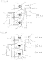
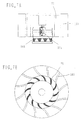
- Fig. 7 shows a wind power generator which carried out the power generation by receiving the wind from a whole periphery and in this generator a wind direction guide 107 is arranged in a surrounding portion of a centrifugal blade 75 and in any wind direction the wind can work validly to the blade.
- Fig. 7A shows a whole cross-sectional view
- Fig. 7B is a cross-sectional view showing a relationship between a blade 75 and a wind direction guide 107.
- a reference numeral 15a indicates a generator.
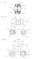
- Fig. 8 is an inner-rotor type induction motor.
- Fig. 8A is a cross-sectional structure showing the induction motor having a rotor 113 which is constituted by combination of a rotor 113 formed by a rotor bar 111 with an electromagnet 120
- Fig. 8B is a cross-sectional structure showing the induction motor having a conventional rotary bar rotor 113'.
- the electric power is applied to coils wound around in stators 112 and 112' by cords 119 and 119', the rotation magnetic field occurs and the electromagnetic force generates between the current generated in the rotors 113 and 113' and then it works as the electric motor.
- a rotor 113 is driven from an outside according to the power source and to the coil 115 wound around in the stators 112 and 112' the voltage occurs in response to the rotation number and to electric power take-in cords 119 and 119' the load such as the resistance is connected and then current flows into and the electric power is supplied.
- the generation voltage of the coil is proportional to the magnetic flux density of the air gap between the stator and the rotor and also is proportional to the rotation number.
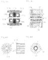
- Fig. 9 is an explanatory view showing the rotor according to the present invention and in Fig. 9A1, Fig. 9A2 and Fig. 9A3 show respectively the induction motor in which a notch portion C is provided on an outer peripheral portion and the current having flown the rotor bar 11a flows the conductive plate 126 in which the outer periphery is cut off and the inner peripheral portion of the disc conductive plate 127' in which the electric resistance of the outer peripheral portion is increased and then the activation and the output characteristic are improved.
- the magnetic resistance is increased by surrounding the ferro-magnetic substance arranged in the both wall sides of the conductive plate 126 and a disc conductive plate 126' and the iron core 134 and the in response to the height of the frequency the current is limited and then an activation characteristic and the output characteristic to the rotation number can be improved.
- a rotor bar 125 arranged in the iron core inner peripheral portion has the similar operation to the that of the conductive plate 126 and the disc conductive plate 126' and by arranging the ferro-magnetic substance 141 in the vicinity the effects can be strengthen.
- the width in the axial direction of the rotor iron core 124a is formed larger than the axial direction width of the stator iron core 112a, the magnetic flux density can be reduced.
- the electric circuit between the conductive plate 126 provided at the central portion and the disc conductive plate 126' and an end ring 123a is formed short as soon as possible, and then the output improvement and the efficiency-up can be improved.
- a reference numeral 115 indicates a stator winding
- a reference numeral 118 indicates a shaft.
- a reference numeral 127a indicates a penetration hole which is provided on an outer peripheral portion of the conductive plate 126 and the disc conductive plate 126' and a rotor bar 111a is penetrated.
- a reference numeral 128 indicates a penetration hole which is provided on an inner peripheral portion of the conductive plate 126 and the disc conductive plate 126' and a rotary bar 115 is penetrated.
- a reference numeral 129a indicates a penetration hole of the shaft 118a.
- an electromagnetic coil 120b is arranged, using the direct current for flowing the this electromagnetic coil 120b the direct current magnetic field is formed and using the alternating current with the single phase or the multi-phase the rotation magnetic field is formed, and the activation characteristic tic and the output characteristic of the rotating machine can be improved.
- a reference numeral 112b indicates a stator iron core
- a reference numeral 115b indicates a rotor iron core
- a reference numeral 118b indicates a shaft.
- a reference numeral 123b indicates an end ring
- a reference numeral 127b indicates a penetration hole of the rotor bar
- a reference numeral 129b indicates a penetration hole of the shaft 118b.
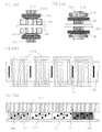
- Fig. 10 an example for realizing the required characteristics of the rotating machine by combining the cage type rotor shown in Fig. 9B1 and the coil conductive member. according to the present invention.
- Fig. 10A1 is similar to that of Fig. 9B1 and the explanation thereof will be omitted.
- Fig. 10A2 shows a rotor in which a rotor bar 125a is arranged in an inner periphery of a rotor iron core 124c and in an outer peripheral portion a coil 130 is arranged.
- the activation characteristic and the generator characteristics are coped with the coil 130, and the coil 130 is used mainly for varying widely the characteristic of the near synchronous speed shown in a graph of Fig. 12A.
- a reference numeral 112c indicates a stator iron core
- a reference numeral 115c indicates a rotor iron core
- a reference numeral 118c indicates a shaft.
- Fig. 10A3 shows a rotor in which a rotor bar 125a is arranged in an inner periphery of a rotor iron core 124c and at an outer peripheral portion a coil 130a is arranged and then the activation characteristic and the generator characteristic can be coped with the rotor bar 125a, and the coil 130a varies mainly widely the characteristic in the near synchronous speed as shown in a graph of Fig. 12C.
- a reference numeral 112d indicates a stator iron core
- a reference numeral 115d indicates a rotor iron core
- a reference numeral 118d indicates a shaft.
- Fig. 10A4 shows an example, with a similar constitution shown in Fig. 10A3, in which a thickness of the rotor iron core 124d is formed thicker than a thickness of the stator iron core 112e.
- the characteristic in the near synchronous speed is varied widely with the coil 130b as shown in a graph of Fig. 12C and the hangover effect of the iron core is aimed and then the whole output characteristic and the efficiency improvement can be attained.
- a reference numeral 112e indicates a stator iron core
- a reference numeral 115e indicates a stator winding
- a reference numeral 118e indicates a shaft
- a reference numeral 125b indicates a rotor bar.
- Fig. 10A5 and Fig. 10A6 show examples in which rotor bars 125c and 125d arranged in the vicinity of the inner periphery of the rotor iron cores 124e and 124f and single or plural conductive plates 126b and 126c are put side by side.
- Reference numerals 112f and 112g indicate stator iron cores
- reference numerals 115f and 115g indicate stator windings
- reference numerals 118f and 118g indicate shafts
- reference numerals 130c and 130d indicate coils.
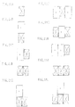
- Fig. 11 is an explanatory view showing an example of a rotor structure for preventing the deformation and the fly out according to the centrifugal force acted on the iron core accompanying with the rotation in a case the rotor iron core is divided to insert the magnets.
- Fig. 11A shows a cross-sectional view of the stator and the rotor of the rotating machine to which the present invention is applied.
- a reference numeral 112h indicates a stator iron core, and a reference numeral 115h indicates a stator winding.
- the rotor iron core 124h is separated in a central portion by a conductive plate 126d and a reinforcement plate and to the both side faces of the rotor iron core 124h, an end ring 123c is arranged and to an outer peripheral portion a rotor bar 111d is arranged.
- a ring shape projection 131 is provided to the end ring 123c and to the iron core 124h a ring shape groove 135 which engaged with the projection 131 is provided.
- a reference numeral 127c indicates a hole which is provided on the divided iron core 124h in which the rotor bar 111d penetrates, and a reference numeral 134 indicates a spacer for supporting and fixing the divided iron core 124h.
- Fig. 11C shows an example in which a conductive plate 126d constituted to separate the divided iron core 124h is utilized as a reinforcement plate for preventing the deformation and the fly out by the centrifugal force.
- a reference numeral 127s is a hole in which the rotor bar 111d provided on the conductive plate 126d penetrates.
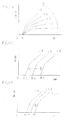
- Fig. 12 are graphs showing the variation (the change) of the characteristics of the various kinds induction generators.
- Fig. 12A shows the characteristic changes of the generator due to the resistance change of the conductive substance of the rotor. The resistance becomes large in proportion to from a graph c1 to a graph c5.
- Fig. 12B is a graph showing the characteristic in which the frequency of the exciting use power source is varied. The power source frequency becomes large in proportion to from a graph c6 to a graph c8.
- Fig. 12C is a graph showing the change in the characteristics in which the voltage of the exciting use power source is varied and the characteristic in the near synchronous speed is varied widely.
- a graph c10 is one of the condition before the characteristic change and a graph c9 is one in which the voltage having the reversal phase to the current for flowing the rotor winding is added, under the condition where the rotation number before the alternation is lowered the characteristic can be moved in parallel.
- a graph c11 is one in which the voltage having the same phase to the current for flowing the rotor winding is added, under the condition where the rotation number before the alternation is raised the characteristic can be moved in parallel.
- Fig. 13 is an example in which the widths of the rotor iron cores 124i, 124j and 124m are extended over than the axial direction widths of the stator iron cores 112i and 112j and the hangover portion rotor bar 111e and the winding 130e can be used effectively, and then the characteristics such as the performance improvement and the efficiency improvement can be attained. Namely, the diameters of the end ring 123d and a coil end E of the rotor winding 130e are formed small as possible, for example less than 1/3 of the outer diameter of the rotor, and they are arranged in the vicinity of the shafts 118i and 118j.
- the magnetic field formed by the current for flowing the rotor bar increases the magnetic field in the air gap portion.
- the iron cores 124j, 124k and 124 formed by the sintering and laminated layer are provided.
- the magnetic flux formed by the current I passes through to the outside portion once and passes through the iron cores 124k and 124n and returns to the air gap from the adjacent pole iron core.
- Reference numerals 115i, 115 j indicates stator windings
- a reference numeral 126e is a conductive plate which works the same role of the deep groove rotor bar and the end ring 123d.
- Fig. 14 is an example in which an axial direction length of the rotor iron cores 124o and 124r is formed longer that the length of the stator iron cores 112k and 112m and the characteristic improvement and the efficiency improvement can be obtained.
- Fig. 14A1 and Fig. 14A2 are examples in which the stator iron core 112k is extended to the hangover rotor bar 111f and the characteristic improvement is obtained by an additional action between the current I for flowing the hangover rotor bar 111f and the stator winding 115k.
- Reference numerals 124p and 124q are iron cores which are made by the sintering material and have the small eddy loss.
- a reference numeral 118k indicates a shaft, and a reference numeral 126f indicates a conductive plate.
- Fig. 15 is a rotary machine in which in the windings of the stator and the rotor slot-less cylindrical shape iron cores 112n and 124u are fixed to the coils 115n and 130f using an adhesive agent etc. and then the cogging torque can be made small and the activation torque can be made small and the efficiency can be improved.
- a fastening projection 151 provided on cylindrical shape holding members 150 and 150a the hole provided on the cylindrical iron cores 112n and 124u are utilized.
- To the adhesive agent 160 magnetic substance powders 160 are immersed.
- Fig. 15A1 is an explanatory view showing an example in which to the stator core a slit-less iron core is applied and Fig. 15A2 is an explanatory view showing an example in which to the rotor core a slit-less iron core is applied.
- a reference numeral 111g indicates a rotor bar of a cage type rotor and a reference numeral 123s indicates an end ring of the cage type rotor.
- Reference numerals 118n and 1180 indicate shafts and a reference numeral 112o indicate a stator iron core and a reference 115o indicates a stator iron core.
- Fig. 15A3 is a view in which the winding is developed in a circumferential direction.
- Fig. 15A4 is a cross-sectional view in which Fig. 15A3 is seen from a side face and the relationship between the cylindrical iron core 112, the coil 115 and the holding member 150 and the fastening projection 151 is shown.
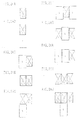
- Fig. 16 shows an outer-rotor type generator.
- Fig. 16A is a cross-sectional view showing the generator having a rotor 202 which is constituted by magnets 214 or electromagnets 242 and 243 and a combination thereof according to the present invention
- Fig. 16B is a cross-sectional view showing a generator, having a conventional cylindrical type magnet rotor 202'.
- Fig. 17 is an example showing the outer-rotor type generator
- Fig. 18 is an example showing the inner-rotor type generator.
- the generator is constituted by a power transmitting outer frame 210 in which a rotor material is made of a non-magnetic substance, six divided iron cores 213 and six magnets 214.
- a space sandwiched by the stator, a portion and b portion of a side outer frame, the outer frame 210 and the iron core 213 is constituted by a non-magnetic substance. Since the twice times of the radial direction length of the magnet 214 is made larger than the circumferential direction length of one pole part of the air gap portion, the magnetic flux in the air gap portion can be made larger than the magnetic flux of the magnet 214.
- Fig. 18B is an example in which the magnets 214a and 214b having the different strength are inserted into a slit.
- Fig. 18C is an example in which a cross-section of the magnet is a trapezoid shape.
- Fig. 18D is an example in which two magnets having the same strength are increased per one pole.
- Fig. 18E is an example in which two kinds magnets are used and a main magnet 214 determines the magnetic field in the air gap and a magnet 214' adjusts minutely the magnetic field.
- Fig. 18F is an example in which to the conventional cylindrical magnet the magnet according to the present invention is combined.
- Fig. 18A - Fig. 18F show the inner-rotor type generator and have a reversal structure of the outer-rotor type generator shown in Fig. 17 and since the structure thereof is basically to the same one the explanation thereof will be omitted.
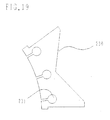
- Fig. 19 is a plan view showing an example of the divided iron core part of the rotor of the above stated outer-rotor type generator and facing to the air gap between the stator three slots 231 are provided.
- Fig. 20 is an example in which using the structure shown in Fig. 19A to the rotor of the outer-rotor type generator the cage type rotor is formed.
- the structure of a cage type rotor part is shown in Fig. 20B and Fig. 20C and is made of the conductive member such as aluminum and brass and by two side sheets 218 and plural bars 219 the rotor is formed integrally using the caulking and die casting.
- the magnet according to the present invention is extended to the axial direction, in a case shown in Fig. 20B, the iron core is separated by the side plate 218.
- the radial direction length of the side plate 218 is formed small as possible, the cross-section thereof is formed same and is extended to the axial direction.
- the side plate is arranged in the inner peripheral face of the magnet iron core (in the case of the inner-rotor type generator, to the outer peripheral face thereof), to concentrate the magnetic flux from the magnet which is extended to the both sides and the electromagnet to the stator air gap and further the side plate is arranged with a stepwise part 232, which is provided to prevent the leakage from the side face of the stator, of the rotor iron core and thereby the affect to the magnetic path can be lessened.
- Fig. 20D is an example in which only the magnet 214 is extended in the axial direction of the rotor and Fig. 20E is an example in which electromagnets 242 and 243 are added to the both sides of the rotor magnet 214 faced with the stator 212.
- a magnetic flux leakage gap 252 of the electromagnet 242 and a magnetic flux leakage gap 253 of the electromagnet 243 are provided to work validly to the prevention of a short-circuit of the magnetic flux to the stator.
- Fig. 21 is an example of a case where there is a limitation of the space of the magnetic pole arrangement of the electric motor and the generator as shown in Fig. 17F, utilizing validly the limited magnetic pole space, a whole face or a part of the solid face the magnets are arranged organically and to the air gap portion the magnetic flux can be concentrated at the maximum.
- a magnet 214a'' and a magnet 214d arranged to the axial direction magnetic pole face can be formed a ring shape and can be formed an integral structure.
- a cap shape can be formed.
- the magnet 214c is a cylindrical shape magnet which is arranged in the outer peripheral portion of the magnetic pole and on the periphery thereof an iron core 213a for forming the magnetic path of the magnetic flux is arranged. To an outer side of the magnet 214d an iron core 213b is arranged and the magnet 214d is worked validly. All magnets are settled and arranged to concentrate the magnetic flux to the air gap portion and have the polarity of the respective magnet of N and S shown in figures.
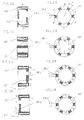
- Fig. 22 and Fig. 23 are explanatory views showing a donut shape electromagnet structures which are enable to combine with another magnet and electromagnet.
- Fig. 22 shows an example in which the magnet poles are two poles and
- Fig. 23 shows an example in which the magnet poles are six poles.
- the detail explanation of the electromagnets will be explained referring to Fig. 22.
- Fig. 22A and Fig. 22B to an outer periphery two magnetic poles of N and S are formed, and when they are used as the rotor it can apply to the inner-rotor type generator.
- Fig. 22C and Fig. 22D show the structures having the magnetic pole on the inner peripheral face and have the reversal structures shown in Fig. 22A and Fig. 22B.
- Fig. 22E and Fig. 22F the magnetic poles are the right face and in Fig. 22G and Fig. 22H the magnetic poles are the left face.
- Fig. 24 is a schematic view showing four kind electromagnets of the six pole electric machine and the magnets of the inner and outer rotor.
- Fig. 24A1 shows an outer periphery magnetic pole type electromagnet
- Fig. 24A2 shows an outer periphery magnetic pole type electromagnet
- Fig. 24A3 shows a right face magnetic pole type electromagnet
- Fig. 24A4 shows a left face magnetic pole type electromagnet.
- Fig. 24A5 shows an outer-rotor use magnet
- Fig. 24A6 shows an inner-rotor use magnet.
- Fig. 25 is an example showing a combination of the inner-rotor use magnets and electromagnets and Fig. 26 is an example showing a combination of the outer-rotor use magnets and electromagnets.
- Fig. 26A is an example in which the magnetic pole is formed with only one outer periphery magnetic pole type electromagnet.
- Fig. 26B is an example in which one electromagnet is arranged in an interior portion and one magnet is arranged in an outer side.
- Fig. 26C is an example in which the magnet and the left face magnetic pole type electromagnet.
- Fig. 26D is an example in which two electromagnets are arranged and Fig. 26I is an example in which three electromagnets are arranged.
- Fig. 26E and Fig. 26F are examples in which the magnet is combined to the outer face of the electromagnet shown in Fig. 26D and Fig. 26I.
- Fig. 26F, Fig. 26G and Fig. 26H are examples in which to one magnet or electromagnet two other magnets or electromagnets are combined.
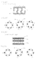
- Fig. 27 and Fig. 28 are examples in which the stator of three phase electric machine using three pieces of the two pole or the six pole inner and outer magnetic pole electromagnets.
- Fig. 27A and Fig. 27B show examples in which the electromagnets are applied to the stator of the alternating current two poles of the outer-rotor type rotor.
- Fig. 27A shows the stator and Fig. 27B shows a positional relationship of the electromagnets during a combination of the respective phase in which it shifts with electric angel of 120 degrees.
- Fig. 27C and Fig. 27D show examples in which the electromagnets are applied to the stator of the inner-rotor type rotor.
- Fig. 27A and Fig. 27B show examples in which the electromagnets are applied to the stator of the inner-rotor type rotor.
- FIG. 28 is an example in which the electromagnets are applied to the stator of the three phase six pole electric machine.
- Fig. 28A shows the stator and
- Fig. 28B shows a positional relationship of the electromagnets during a combination of the respective phase in which it shifts with electric angel of 120 degrees.
- Fig. 28C and Fig. 28D show examples in which the electromagnets are applied to the stator of the inner-rotor type rotor.
- Fig. 29 is an explanatory view showing a structure of two pole electromagnet iron core and shows the structure which is enable to manufacture the iron core using only one manufacturing tool.
- Fig. 29A shows one winding use outer periphery magnetic pole of the iron core
- Fig. 29B shows one winding use inner periphery magnetic pole of the iron core.
- An iron core 272 forms the outer periphery magnetic pole type
- an iron core 273 forms the inner periphery magnetic pole type.
- the structures shown in Fig. 29E, Fig. 29F, Fig. 29G and Fig. 29H, Fig. 29I, Fig. 29J are validly to utilize as the three-phase electric machine.
- Fig. 30 is an explanatory view showing an iron core structure to lessen the eddy current loss of the alternating current electromagnet.
- Fig. 30A and Fig. 30B show the iron core structures in which the sintering member and the iron powder are solidified by the bonding material.
- Fig. 30C and Fig. 30D show examples of a combination of an electromagnetic steel plate 281b with an iron core 281a in which the sintering material and the iron powder are bonded by the bonding material.
- Fig. 30E and Fig. 30F show examples of a combination of an electromagnetic steel plate 282b with an iron core 282a which constitutes a squeezing structure of a thick iron plate having slits 283.
Landscapes
- Engineering & Computer Science (AREA)
- Power Engineering (AREA)
- Life Sciences & Earth Sciences (AREA)
- Sustainable Energy (AREA)
- Sustainable Development (AREA)
- Combustion & Propulsion (AREA)
- Chemical & Material Sciences (AREA)
- Mechanical Engineering (AREA)
- General Engineering & Computer Science (AREA)
- Permanent Magnet Type Synchronous Machine (AREA)
- Connection Of Motors, Electrical Generators, Mechanical Devices, And The Like (AREA)
- Facsimile Scanning Arrangements (AREA)
- Combination Of More Than One Step In Electrophotography (AREA)
Abstract
Description
Claims (10)
- An electric motor and a generator which is constituted using the electric motor as a power source and is used in an electric power line, characterized in thatan electric drive generator is provided integrally or is provided separately,thereby a power generation function is obtained.
- An electric motor and a generator which is constituted using the electric motor as a power source and is used in an electric power line, characterized in thatin a case of a power generation function, the generator is activated and is risen up near to a synchronous speed and the generator is carried out a switch-on operation;in a case of an electric power generation function, the electric motor is made once in non-load condition and is activated and is risen up near once to a synchronous speed from a stop condition and the generator is carried out a switch-on operation; andthereby an induction motor excited on an electric power system line or an alternating current is constituted.
- A fluid machine having a blade or a water turbine and a rotating machine, characterized in thatin a case of a propelling machine, a twist angle is made reversal, andin a case of a centrifugal machine, an intake port of the fluid is changed over from an air inhale side to an air exhaust side;thereby without an alternation of a control circuit, a fluid transportation function is changed over to a power generation system.
- An electric motor and a generator which is constituted using the electric motor as a power source and is used in an electric power line, characterized in thatin every case of a power generation function and a complex function of the electric motor and the generator,when a stop or a power function is changed over to a power generation system, data necessary to control a load condition, an outside portion power condition, a power condition of an outside generator etc. are detected by a sensor; andin accordance with the detected data the stop or the power function is changed over to the power generation system, thereby a whole system is operation-controlled.
- A wind power generation system having an electric motor and a generator for sending air using a blade and for carrying out a wind power generation by taking air into from all direction,
characterized in thata wind direction guide is installed; andan induction motor is constituted as a main electric machine. - A wind power generation system having an electric motor and a generator for sending air using a blade and for carrying out a wind power generation, and having an electric motor and a generator, characterized in thatan inclined magnetic field is formed in a flow passage using one selected from a single permanent magnet, a single electromagnet, plural permanent magnets and plural electromagnet; andair is moved always according to oxygen in the air and the inclined magnetic field.
- A fluid power generation system having a fluid machine constituted by a blade, a water turbine and a rotating machine, and having an electric motor and a generator, characterized in thatin a case of a single power generation function, the system is activated as the electric motor and the electric motor is risen up near to a synchronous speed; andin a case of a complex function of the electric motor and the generator, a rotation magnetic field is varied electrically, and the system is activated as the electric motor and the electric motor is risen up near to a synchronous speed.
- A rotating machine having a stator and a rotor,
characterized in thata single conductive member or plural conductive members are provided with a sandwich shape in a laminated iron core;
andon an outer peripheral portion of the conductive member, a groove is provided to not flow current shortly between rotor bars. - A rotating machine having a stator and a rotor,
characterized in thata single disc member or plural disc member are provided in a laminated iron core of the rotor; andthe laminated iron core of the rotor is projected from an axial direction length of an iron core of the stator. - A rotating machine according to claim 9, characterized in thatan extension portion of a rotor bar is formed on an outer peripheral portion of an end ring;thereby a magnetic filed of an overhang portion of the laminated iron core of the rotor is formed validly.
Applications Claiming Priority (4)
| Application Number | Priority Date | Filing Date | Title |
|---|---|---|---|
| JP2000147872 | 2000-05-19 | ||
| JP2000147872 | 2000-05-19 | ||
| JP2000147881 | 2000-05-19 | ||
| JP2000147881 | 2000-05-19 |
Publications (2)
| Publication Number | Publication Date |
|---|---|
| EP1158644A2 true EP1158644A2 (en) | 2001-11-28 |
| EP1158644A3 EP1158644A3 (en) | 2004-09-22 |
Family
ID=26592217
Family Applications (1)
| Application Number | Title | Priority Date | Filing Date |
|---|---|---|---|
| EP01304416A Withdrawn EP1158644A3 (en) | 2000-05-19 | 2001-05-18 | Electric motor and generator |
Country Status (4)
| Country | Link |
|---|---|
| US (1) | US7019413B2 (en) |
| EP (1) | EP1158644A3 (en) |
| KR (1) | KR100780018B1 (en) |
| HK (1) | HK1044077A1 (en) |
Cited By (1)
| Publication number | Priority date | Publication date | Assignee | Title |
|---|---|---|---|---|
| ITVI20080247A1 (en) * | 2008-10-23 | 2010-04-24 | Abc Di Bortolan Antonio | DISTRIBUTION SYSTEM OF ELECTRIC ENERGY INCLUDING SYNCHRONOUS GENERATORS WITH PERMANENT MAGNETS FITTED INTERNALLY |
Families Citing this family (28)
| Publication number | Priority date | Publication date | Assignee | Title |
|---|---|---|---|---|
| US7378763B2 (en) * | 2003-03-10 | 2008-05-27 | Höganäs Ab | Linear motor |
| US6914351B2 (en) | 2003-07-02 | 2005-07-05 | Tiax Llc | Linear electrical machine for electric power generation or motive drive |
| AU2005258190A1 (en) * | 2004-06-23 | 2006-01-05 | Energy & Engine Technology Corporation | Method and system for power generation |
| US7116003B2 (en) * | 2004-07-14 | 2006-10-03 | Hamilton Sundstrand Corporation | Aircraft starter/generator electrical system with mixed power architecture |
| KR100688206B1 (en) * | 2005-03-08 | 2007-03-02 | 엘지전자 주식회사 | motor |
| US20070024150A1 (en) * | 2005-08-01 | 2007-02-01 | Syverson Charles D | Electrical machine having centrally disposed stator |
| US20070108850A1 (en) * | 2005-11-17 | 2007-05-17 | Tiax Llc | Linear electrical machine for electric power generation or motive drive |
| CA2662057C (en) * | 2006-09-01 | 2015-06-16 | Vestas Wind Systems A/S | System and method of controlling a wind turbine in a wind power plant |
| US20080277937A1 (en) * | 2007-05-10 | 2008-11-13 | Yung-Tsai Chuo | Torque Motor Type Wind Generator |
| CN101051779B (en) * | 2007-05-15 | 2010-06-16 | 天津市新源电气科技有限公司 | Winding type internal rotor brushless double feed generator and its control device |
| US7956482B2 (en) * | 2008-01-18 | 2011-06-07 | General Electric Company | Speed controlled pitch system |
| US8169182B1 (en) | 2008-06-02 | 2012-05-01 | Denny Kimble | Charging system for an electric vehicle |
| CN102292897B (en) | 2009-01-16 | 2014-04-02 | 科尔风力发电公司 | Segmented stators for axial field devices |
| US8800701B1 (en) | 2009-11-02 | 2014-08-12 | L.R.S. Innovations, Inc. | Electric vehicle with onboard electricity production |
| US20110156400A1 (en) * | 2009-12-31 | 2011-06-30 | Lowe David A | Kinetic Energy Rotation System |
| JP5260591B2 (en) * | 2010-03-30 | 2013-08-14 | 株式会社日立製作所 | Permanent magnet rotating electrical machine and wind power generation system |
| US9154024B2 (en) | 2010-06-02 | 2015-10-06 | Boulder Wind Power, Inc. | Systems and methods for improved direct drive generators |
| EP2723606A4 (en) | 2011-06-24 | 2014-12-24 | L R S Innovations Inc | ELECTRIC VEHICLE |
| US8339019B1 (en) | 2012-07-30 | 2012-12-25 | Boulder Wind Power, Inc. | Structure for an electromagnetic machine having compression and tension members |
| US8736133B1 (en) | 2013-03-14 | 2014-05-27 | Boulder Wind Power, Inc. | Methods and apparatus for overlapping windings |
| GB2522021B (en) * | 2014-01-08 | 2018-02-07 | Protean Electric Ltd | A rotor for an electric motor or generator |
| US10177620B2 (en) | 2014-05-05 | 2019-01-08 | Boulder Wind Power, Inc. | Methods and apparatus for segmenting a machine |
| WO2016126342A1 (en) | 2015-02-03 | 2016-08-11 | Williams International Co., L.L.C. | Turbo-electric turbo-compounding system |
| US11105259B2 (en) | 2015-02-03 | 2021-08-31 | Williams International Co., L.L.C. | Turbo-electric turbo-compounding method |
| US11105258B2 (en) | 2015-02-03 | 2021-08-31 | Williams International Co., L.L.C. | Turbo-electric turbo-compounding system |
| KR102138339B1 (en) * | 2018-10-24 | 2020-07-27 | 주식회사 엠플러스 | Sound vibration actuator |
| CN109586497B (en) * | 2018-12-10 | 2020-07-10 | 贾立进 | Electric energy and mechanical energy reciprocal conversion device |
| US11289985B2 (en) * | 2019-08-09 | 2022-03-29 | Hamilton Sundstrand Corporation | Dual stator machine with a rotor magnet set configured to minimize flux leakage |
Family Cites Families (13)
| Publication number | Priority date | Publication date | Assignee | Title |
|---|---|---|---|---|
| GB412850A (en) * | 1933-12-02 | 1934-07-05 | Participation Financiere Elect | Improvements in and relating to induction motors of the squirrel cage type |
| CH197079A (en) * | 1935-08-01 | 1938-04-15 | Duenner Prof Ernst | Noiseless electric machine. |
| GB905632A (en) * | 1959-10-01 | 1962-09-12 | Papst Hermann | Improved electrical induction motor having a stator radially surrounded by an external rotor |
| DE1206818B (en) * | 1963-07-17 | 1965-12-09 | Voith Gmbh J M | Machine set for pumped storage systems, consisting of motor generator, hydraulic main engine and Francis auxiliary turbine |
| DE1488703A1 (en) * | 1965-08-20 | 1969-04-24 | Sabev Dipl Ing Todor | Solid runner made of ferromagnetic segments |
| US4204126A (en) * | 1975-10-21 | 1980-05-20 | Diggs Richard E | Guided flow wind power machine with tubular fans |
| JPS62104403A (en) * | 1985-10-29 | 1987-05-14 | Isuzu Motors Ltd | Driving device for vehicle |
| JPH01123460U (en) * | 1988-02-12 | 1989-08-22 | ||
| JP3344848B2 (en) * | 1994-11-04 | 2002-11-18 | アイシン・エィ・ダブリュ株式会社 | Launching device |
| JPH08251886A (en) * | 1995-02-22 | 1996-09-27 | Taiken Boku | Electric motor and generator |
| JP2000156947A (en) * | 1998-11-17 | 2000-06-06 | Yukio Kinoshita | Magnet-type motor and power generator |
| DE10162214B4 (en) * | 2000-12-19 | 2014-02-13 | Denso Corporation | Motor vehicle engine / generator unit with synchronous machine |
| KR20190000900U (en) * | 2019-03-07 | 2019-04-10 | 문병승 | The ruffler foot for a sewing machine |
-
2001
- 2001-05-16 US US09/855,563 patent/US7019413B2/en not_active Expired - Fee Related
- 2001-05-18 EP EP01304416A patent/EP1158644A3/en not_active Withdrawn
- 2001-05-18 KR KR1020010027165A patent/KR100780018B1/en not_active Expired - Fee Related
-
2002
- 2002-05-28 HK HK02103983.1A patent/HK1044077A1/en unknown
Cited By (1)
| Publication number | Priority date | Publication date | Assignee | Title |
|---|---|---|---|---|
| ITVI20080247A1 (en) * | 2008-10-23 | 2010-04-24 | Abc Di Bortolan Antonio | DISTRIBUTION SYSTEM OF ELECTRIC ENERGY INCLUDING SYNCHRONOUS GENERATORS WITH PERMANENT MAGNETS FITTED INTERNALLY |
Also Published As
| Publication number | Publication date |
|---|---|
| HK1044077A1 (en) | 2002-10-04 |
| US20010042983A1 (en) | 2001-11-22 |
| US7019413B2 (en) | 2006-03-28 |
| EP1158644A3 (en) | 2004-09-22 |
| KR100780018B1 (en) | 2007-11-27 |
| KR20010106270A (en) | 2001-11-29 |
Similar Documents
| Publication | Publication Date | Title |
|---|---|---|
| EP1158644A2 (en) | Electric motor and generator | |
| JP3873634B2 (en) | Wind power generation system | |
| CN108011484B (en) | A magnetic gear composite motor | |
| EP2429063A1 (en) | Ac elelctric machine with claw poles | |
| CN104795953A (en) | Switch reluctance machine with stator separated from rotor | |
| JP2002191123A (en) | Motor and power generation system | |
| CN111211659B (en) | A Stator Modular Ring Winding Double Rotor Permanent Magnet Motor | |
| JP4576873B2 (en) | Permanent magnet motor, driving method and manufacturing method thereof, compressor, blower and air conditioner | |
| CN106992644A (en) | A kind of five degree of freedom composite excitation magnetic suspension switched reluctance motor | |
| WO2023216635A1 (en) | Axial flux switched reluctance motor having wide and narrow stator poles, and control method therefor | |
| MXPA06012956A (en) | "hybrid electric reluctance motor". | |
| CN114552925A (en) | A Stator Permanent Magnet Shaft Radial Mixed Magnetic Field Permanent Magnet Flux Switching Motor | |
| CN204538923U (en) | A kind of rotor sectional type switched reluctance machines | |
| CN112436705A (en) | Switched reluctance motor | |
| CN208445460U (en) | A kind of spoke type for electric vehicle interlocks rotor permanent magnet synchronous motor | |
| CN213637435U (en) | Switched reluctance motor | |
| CN210405045U (en) | Axial Parallel Compound Motor | |
| CN210608875U (en) | Radial magnetic field composite magnetic flux switching motor | |
| CN116191800B (en) | Short magnetic circuit shaft radial mixed magnetic flux switch reluctance motor and control method | |
| RU2246168C1 (en) | Face-type electrical machine | |
| WO2009051515A1 (en) | Synchronous electrical machine | |
| RU2311715C1 (en) | Synchronous electrical machine | |
| CN116073616A (en) | A magnetic field decoupling hybrid flux switched reluctance motor and its control method | |
| JP2006014595A (en) | Electric motor and power generating system | |
| CN119182266B (en) | Axial magnetic flux magnetic field modulation permanent magnet motor with double-layer magnetic conduction blocks |
Legal Events
| Date | Code | Title | Description |
|---|---|---|---|
| PUAI | Public reference made under article 153(3) epc to a published international application that has entered the european phase |
Free format text: ORIGINAL CODE: 0009012 |
|
| AK | Designated contracting states |
Kind code of ref document: A2 Designated state(s): AT BE CH CY DE DK ES FI FR GB GR IE IT LI LU MC NL PT SE TR |
|
| AX | Request for extension of the european patent |
Free format text: AL;LT;LV;MK;RO;SI |
|
| RIC1 | Information provided on ipc code assigned before grant |
Ipc: 7F 03D 9/02 B Ipc: 7F 03B 13/06 B Ipc: 7H 02J 3/38 B Ipc: 7H 02J 15/00 B Ipc: 7H 02J 3/28 B Ipc: 7H 02K 17/00 A |
|
| PUAL | Search report despatched |
Free format text: ORIGINAL CODE: 0009013 |
|
| AK | Designated contracting states |
Kind code of ref document: A3 Designated state(s): AT BE CH CY DE DK ES FI FR GB GR IE IT LI LU MC NL PT SE TR |
|
| AX | Request for extension of the european patent |
Extension state: AL LT LV MK RO SI |
|
| RIC1 | Information provided on ipc code assigned before grant |
Ipc: 7F 03D 9/02 B Ipc: 7F 03B 13/06 B Ipc: 7H 02J 3/38 B Ipc: 7H 02J 15/00 B Ipc: 7H 02J 3/28 B Ipc: 7H 02K 17/16 A |
|
| AKX | Designation fees paid |
Designated state(s): DE DK FR GB |
|
| 17P | Request for examination filed |
Effective date: 20050510 |
|
| 17Q | First examination report despatched |
Effective date: 20051207 |
|
| STAA | Information on the status of an ep patent application or granted ep patent |
Free format text: STATUS: THE APPLICATION IS DEEMED TO BE WITHDRAWN |
|
| 18D | Application deemed to be withdrawn |
Effective date: 20081202 |
|
| REG | Reference to a national code |
Ref country code: HK Ref legal event code: WD Ref document number: 1044077 Country of ref document: HK |