EP1158176B1 - Rastverbindung für ein Spiralgehäuse - Google Patents
Rastverbindung für ein Spiralgehäuse Download PDFInfo
- Publication number
- EP1158176B1 EP1158176B1 EP01108818A EP01108818A EP1158176B1 EP 1158176 B1 EP1158176 B1 EP 1158176B1 EP 01108818 A EP01108818 A EP 01108818A EP 01108818 A EP01108818 A EP 01108818A EP 1158176 B1 EP1158176 B1 EP 1158176B1
- Authority
- EP
- European Patent Office
- Prior art keywords
- guide
- component according
- height
- crosspiece
- elevations
- Prior art date
- Legal status (The legal status is an assumption and is not a legal conclusion. Google has not performed a legal analysis and makes no representation as to the accuracy of the status listed.)
- Expired - Lifetime
Links
- 239000002184 metal Substances 0.000 claims abstract description 32
- 229920003023 plastic Polymers 0.000 claims abstract description 15
- 239000004033 plastic Substances 0.000 claims abstract description 15
- 239000000463 material Substances 0.000 claims abstract description 6
- 238000004080 punching Methods 0.000 claims description 21
- 230000015572 biosynthetic process Effects 0.000 claims 1
- 238000005755 formation reaction Methods 0.000 claims 1
- 238000005304 joining Methods 0.000 description 4
- 238000004519 manufacturing process Methods 0.000 description 4
- 238000003780 insertion Methods 0.000 description 2
- 230000037431 insertion Effects 0.000 description 2
- 238000009434 installation Methods 0.000 description 2
- 238000000034 method Methods 0.000 description 2
- 230000000630 rising effect Effects 0.000 description 2
- 239000011248 coating agent Substances 0.000 description 1
- 238000000576 coating method Methods 0.000 description 1
- 230000007423 decrease Effects 0.000 description 1
Images

Classifications
-
- F—MECHANICAL ENGINEERING; LIGHTING; HEATING; WEAPONS; BLASTING
- F04—POSITIVE - DISPLACEMENT MACHINES FOR LIQUIDS; PUMPS FOR LIQUIDS OR ELASTIC FLUIDS
- F04D—NON-POSITIVE-DISPLACEMENT PUMPS
- F04D29/00—Details, component parts, or accessories
- F04D29/60—Mounting; Assembling; Disassembling
- F04D29/62—Mounting; Assembling; Disassembling of radial or helico-centrifugal pumps
- F04D29/624—Mounting; Assembling; Disassembling of radial or helico-centrifugal pumps especially adapted for elastic fluid pumps
- F04D29/626—Mounting or removal of fans
-
- F—MECHANICAL ENGINEERING; LIGHTING; HEATING; WEAPONS; BLASTING
- F04—POSITIVE - DISPLACEMENT MACHINES FOR LIQUIDS; PUMPS FOR LIQUIDS OR ELASTIC FLUIDS
- F04D—NON-POSITIVE-DISPLACEMENT PUMPS
- F04D29/00—Details, component parts, or accessories
- F04D29/40—Casings; Connections of working fluid
- F04D29/42—Casings; Connections of working fluid for radial or helico-centrifugal pumps
- F04D29/4206—Casings; Connections of working fluid for radial or helico-centrifugal pumps especially adapted for elastic fluid pumps
- F04D29/4226—Fan casings
Definitions
- the invention relates to a component made of at least one plastic element and at least one metallic stamping element with at least one boundary edge, which is guided in a guide of the plastic element.
- Components of this type are, for example, components of housings, in particular of Spiral casing for radial blowers. These consist of two side parts Plastic and a metal casing, which is in the guide grooves of the side parts is held. To produce the casing, it is made of a metallic Sheet metal punched out. The punching process creates an edge on one side a rounded shape and on the other side in the punching direction has protruding punch burr.
- This punching ridge is when assembling the Housing shell with the plastic side parts - especially when inserting into the narrow Guide groove - a hindrance, since the protruding, usually sharp-edged ridge easily moves with it hooked the nutrand.
- the invention has for its object to provide a generic component that is simple and inexpensive to manufacture and assemble, which Plastic element and the metallic stamping element with each other without play in the Leadership should be connectable.
- the punching element has several spaced from each other, in the direction of one which arises during the punching process Stamped burr has elevations, the distance to the boundary edge is less than the depth of the guide and its height is at least the height of the Stamped burr corresponds, the width of the guide approximately the material thickness of the Punching element plus the amount of increases.
- the invention is based on the knowledge that the deburring of the metallic Component can then be omitted if the width of the guide of Plastic element, for example designed as a guide groove, the material thickness of the punching element plus the resulting burr.
- the wide guide groove ensures a play-free fit Punching element according to the invention increases in the direction of the punch burr in the area the boundary edge on the inside of the assembled components the guide groove are arranged and their height is the height of the punch burr exceeds.
- the width of the guide groove corresponds approximately to the material thickness of the Punching element plus the height of the increases.
- the invention Increases thus enable broadening of the leadership or the Guide groove so that the deburring punching element can be inserted is unproblematic, and on the other hand a play-free connection of the Plastic element with the metallic stamping element.
- the guide according to the invention has the an outer and an inner web is formed from the outer web molded snap hooks which engage in openings of the punching element. This "clip system" enables simple and quick installation.
- the guide groove advantageously has at several points from the Groove base formed in the direction of the stamping element, the one Ensure axial tolerance compensation. Vibrations of the punching element or Housing shell, for example excited by a drive motor, are thereby locked out.
- the guide groove advantageously has Joining aid on a guide web connecting the outer and the inner web, on which a notch of the stamping element is placed or in assembled state is inserted into this notch.
- each Punching element is in front of the openings cooperating with the snap hooks of the metallic stamping element advantageously a portion of each Punching element by deformation in the direction of the elevations from the Boundary edge led out and forms a rising inclined surface. About. this inclined surface will also point in the direction of the elevations Snap hooks when joining the plastic element with the metallic one Punching element raised and guided into the opening behind it.
- the component according to the invention is that deburring is dispensed with can manufacture inexpensively. Through the guide aids and the functional clip system makes installation quick and easy. At a Use of the components as side parts and housing jacket to produce a Blower housing allows the embodiment of the invention a vibration-free Operation, because the punching element used as the casing is by spring clip vibration-damped in the axial direction and by the elevations in the radial direction.
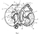
- FIG. 1 shows a component according to the invention, a spiral housing 1 of a radial fan in a semi-assembled state, consisting of a metal stamping element 2, designed as a sheet metal jacket, and two serving as side panels Plastic elements 4, in which there are air inlet openings 6.
- a metal stamping element 2 designed as a sheet metal jacket
- plastic elements 4 in which there are air inlet openings 6.
- Not one Electric motor fan unit shown is in a motor mount 8 at the connection point three struts 10 each, which are approximately centric in the air inlet openings 6 are interconnected, can be used.
- the sheet metal jacket is by inserting it mutually opposite boundary edges 12, in particular its Longitudinal edges, can be connected to these in guides 14 of the side parts (cf. also the Figures 2 and 3).
- Such a guide 14 is preferably as one on the outer edge of the side parts circumferentially arranged guide groove, which by an outer web 18th and an inner web 20 is included.
- the height of the outer web 18 exceeds the height of the inner web 20, whereby on the one hand the housing is stabilized overall and on the other hand the insertion of the Sheet metal jacket in the respective side part is facilitated.
- Figures 2 and 3 show a section of an insertable in the guide groove or boundary edge 12 of the sheet metal jacket connected to the guide groove.
- a burr which is the joining of the Sheet metal jacket with the side parts so hampered that a previous deburring of the Sheet metal jacket is necessary.
- the sheet metal jacket of the spiral housing 1 according to the invention along its two boundary edges 12 several, for example dome-shaped, Elevations 16 spaced apart from one another in the direction of the punch burr are pronounced and the height of which exceeds the height of the punch burr. in the The raised portions are the assembled state of the sheet metal jacket with the side part 16 arranged within the guide groove.
- the width of the invention corresponds approximately to the material thickness of the sheet metal jacket plus the height of the elevations 16, whereby on the one hand the introduction of the non-deburred Sheet metal jacket significantly facilitated and on the other hand a play-free connection of the Sheet metal jacket is made possible with the side part.
- the sheet metal jacket is easy without to get caught, can be used in the guide groove, because of the elevations 16 Avoid contact of the boundary edge 12 with the inside of the inner web 20 becomes.
- the sheet metal jacket according to the invention has opposite the snap hooks 22 in the direction of the elevations 16 rising inclined surface 30.
- This inclined surface 30 meets as an insertion or Assembly aid when joining the two components first onto the nose of the Snap hook 22 and lifts it slightly in the opposite of the elevations 16 Direction.
- the elevations 16 enter the guide groove, which brings the outside of the sheet metal jacket to the inside surface of the outer web 18 is pressed.
- the snap hook 22 is moved along the inclined surface 30 and further raised to finally snap into the locking window 24 of the sheet metal jacket.
- the guide groove Scope distributed guide webs 32 arranged. These guide webs 32 run on the groove base and connect the outer web 18 to the inner web 20.
- the Sheet metal jacket has notches 34 lying opposite the guide webs 32, in which the guide webs 32 in the assembled state of the sheet metal jacket Extend side panels 4.
- the guide webs 32 and the notches 34 are essentially wedge-shaped, the width of the guide webs 32 starting from the groove base 26 in the direction of Sheet metal sheath decreases.
Landscapes
- Engineering & Computer Science (AREA)
- Mechanical Engineering (AREA)
- General Engineering & Computer Science (AREA)
- Connection Of Plates (AREA)
- Structures Of Non-Positive Displacement Pumps (AREA)
- Control Of Motors That Do Not Use Commutators (AREA)
- Structure And Mechanism Of Cameras (AREA)
- Casings For Electric Apparatus (AREA)
- Accessory Devices And Overall Control Thereof (AREA)
Description
- Figur 1
- ein erfindungsgemäßes Spiralgehäuse für ein Radialgebläse mit demontierter Seitenwand;
- Figur 2
- eine Ausschnittvergrößerung der in Figur 1 dargestellten Bereiche I;
- Figur 3
- eine Ausschnittvergrößerung der in Figur 1 dargestellten Bereiche I in zusammengefügtem Zustand;
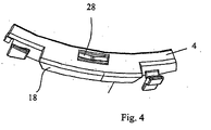
- Figur 4
- eine Ausschnittvergrößerung des in Figur 1 eingezeichneten Bereiches II.
Claims (11)
- Bauteil aus mindestens einem Kunststoffelement (4) und mindestens einem metallischen Stanzelement (2) mit mindestens einer Begrenzungskante (12), die in einer Führung (14) des Kunststoffelementes (4) geführt ist,
dadurch gekennzeichnet, dass das Stanzelement (2) mehrere zueinander beabstandete, in Richtung eines beim Stanzvorgang entstehenden Stanzgrates weisende Erhöhungen (16) aufweist, deren Abstand zur Begrenzungskante (12) geringer als die Tiefe der Führung (14) ist und deren Höhe mindestens der Höhe der Stanzgrates entspricht, wobei die Breite der Führung (14) etwa der Materialstärke des Stanzelementes (2) zuzüglich der Höhe der Erhöhungen (16) entspricht. - Bauteil nach Anspruch 1,
dadurch gekennzeichnet, dass die Erhöhungen (16) als kuppelförmige Ausprägungen ausgeführt sind. - Bauteil nach Anspruch 1 oder 2,
dadurch gekennzeichnet, dass die Führung (14) als Führungsnut ausgebildet ist, die von einem äußeren Steg (18) und einem inneren Steg (20) eingeschlossen ist. - Bauteil nach einem der Ansprüche 1 bis 3,
dadurch gekennzeichnet, dass mindestens ein Steg (18, 20) der Führung (14) mindestens einen in die Führung (14) hineinragenden Schnapphaken (22) aufweist, der in ein in dem metallischen Stanzelement (2) ausgebildetes Rastfenster (24) eingreift. - Bauteil nach einem der Ansprüche 1 bis 4,
dadurch gekennzeichnet, dass die Führungsnut auf ihrem Nutgrund mindestens einen dachförmig in Richtung des geführten metallischen Stanzelementes (2) ausgeformten Federbügel (28) aufweist. - Bauteil nach einem der Ansprüche 1 bis 5,
dadurch gekennzeichnet, dass das metallische Stanzelement (2) .zwischen dem Rastfenster (24) und der Begrenzungskante (12) eine in Richtung des beim Stanzvorgang entstehenden Stanzgrates und von der Öffnung zur Begrenzungskante (12) ansteigende Schrägfläche (30) aufweist. - Bauteil nach einem der Ansprüche 1 bis 6,
dadurch gekennzeichnet, dass die Führungsnut mindestens einen keilförmigen Führungssteg (32) aufweist, der in eine Auskerbung (34) des metallischen Stanzelementes (2) hineinragt, wobei die Breite des Führungsstegs (32) und der Auskerbung (34) in Richtung des Nutgrundes zunimmt. - Bauteil nach einem der Ansprüche 1 bis 7,
dadurch gekennzeichnet, dass das Kunststoffelement (4) als Seitenteil und das metallische Stanzelement (2) als Blechmantel eines Gebläsegehäuses, insbesondere eines Spiralgehäuses (1) eines Radialgebläses ausgeführt ist. - Bauteil nach Anspruch 8,
dadurch gekennzeichnet, dass die Führungsnut umlaufend am Rand des Seitenteils angeordnet ist, wobei die Stege (18, 20) rechtwinklig zur Fläche des Seitenteils angeordnet sind. - Bauteil nach Anspruch 8 oder 9,
dadurch gekennzeichnet, dass das Gebläsegehäuse einen Blechmantel und zwei Seitenteile aufweist, wobei sich die Stege (18, 20) der Seitenteile einander gegenüberliegen und der Blechmantel mit seinen beiden einander gegenüberliegenden Begrenzungskanten (12) jeweils in der Führungsnut des Seitenteils geführt ist. - Bauteil nach einem der Ansprüche 3 bis 10,
dadurch gekennzeichnet, dass die Höhe des äußeren Steges (18) die Höhe des inneren Steges (20) übersteigt.
Applications Claiming Priority (2)
| Application Number | Priority Date | Filing Date | Title |
|---|---|---|---|
| DE20009326U DE20009326U1 (de) | 2000-05-24 | 2000-05-24 | Rastverbindung für ein Spiralgehäuse |
| DE20009326U | 2000-05-24 |
Publications (2)
| Publication Number | Publication Date |
|---|---|
| EP1158176A1 EP1158176A1 (de) | 2001-11-28 |
| EP1158176B1 true EP1158176B1 (de) | 2002-11-20 |
Family
ID=7941958
Family Applications (1)
| Application Number | Title | Priority Date | Filing Date |
|---|---|---|---|
| EP01108818A Expired - Lifetime EP1158176B1 (de) | 2000-05-24 | 2001-04-07 | Rastverbindung für ein Spiralgehäuse |
Country Status (5)
| Country | Link |
|---|---|
| EP (1) | EP1158176B1 (de) |
| AT (1) | ATE228212T1 (de) |
| DE (2) | DE20009326U1 (de) |
| ES (1) | ES2185607T3 (de) |
| PT (1) | PT1158176E (de) |
Families Citing this family (1)
| Publication number | Priority date | Publication date | Assignee | Title |
|---|---|---|---|---|
| DE10346187A1 (de) * | 2003-10-02 | 2005-04-21 | Behr Gmbh & Co Kg | Gebläse |
Family Cites Families (4)
| Publication number | Priority date | Publication date | Assignee | Title |
|---|---|---|---|---|
| DE2950060A1 (de) * | 1979-12-13 | 1981-06-19 | Robert Bosch Gmbh, 7000 Stuttgart | Radialgeblaese |
| EP0195149B1 (de) * | 1985-03-20 | 1990-01-24 | Curver Packaging Ltd. | Behälter mit Deckel |
| US5183301A (en) * | 1991-10-30 | 1993-02-02 | E. J. Brooks Co. | Locking or security seal |
| AU2659795A (en) * | 1994-05-25 | 1995-12-18 | Tec Air, Inc. | Blower housing |
-
2000
- 2000-05-24 DE DE20009326U patent/DE20009326U1/de not_active Expired - Lifetime
-
2001
- 2001-04-07 ES ES01108818T patent/ES2185607T3/es not_active Expired - Lifetime
- 2001-04-07 AT AT01108818T patent/ATE228212T1/de not_active IP Right Cessation
- 2001-04-07 DE DE50100057T patent/DE50100057D1/de not_active Expired - Lifetime
- 2001-04-07 EP EP01108818A patent/EP1158176B1/de not_active Expired - Lifetime
- 2001-04-07 PT PT01108818T patent/PT1158176E/pt unknown
Also Published As
| Publication number | Publication date |
|---|---|
| ATE228212T1 (de) | 2002-12-15 |
| PT1158176E (pt) | 2003-03-31 |
| ES2185607T3 (es) | 2003-05-01 |
| DE20009326U1 (de) | 2001-09-27 |
| HK1038391A1 (en) | 2002-03-15 |
| EP1158176A1 (de) | 2001-11-28 |
| DE50100057D1 (de) | 2003-01-02 |
Similar Documents
| Publication | Publication Date | Title |
|---|---|---|
| EP3957211A1 (de) | Frontblende für eine schublade | |
| DE19506365A1 (de) | Verbinderbefestigungsanordnung | |
| DE19544344A1 (de) | Vorrichtung zum Befestigen einer gedruckten Schaltungskarte in einem Monitorgehäuse | |
| WO2008077858A1 (de) | Halterung | |
| EP0984524A2 (de) | Zweiteiliger elektrischer Steckverbinder | |
| EP0822337B1 (de) | Haltevorrichtung für elektrische Lüfter, insbesondere Kleinstlüfter | |
| DE3210164C2 (de) | Vorrichtung zum Befestigen eines Lüfters in einer Gehäusewand eines elektrischen Gerätes | |
| EP1072179B1 (de) | Baugruppenträger | |
| DE102016220022B4 (de) | Kombination eines Steckers mit einem Deckel | |
| EP1158176A1 (de) | Rastverbindung für ein Spiralgehäuse | |
| EP1375275B1 (de) | Getriebe-Antriebseinheit mit Rastelement | |
| EP3392551B1 (de) | Beleuchtungsmodul | |
| EP1559951B1 (de) | Fahrzeugleuchte und Verfahren zur Montage der Fahrzeugleuchte | |
| EP0648382B1 (de) | Filter-steckverbinder mit schirmgehäuse | |
| EP0562157B1 (de) | Steckverbindung | |
| DE3220456C2 (de) | Lampenträger für Glühlampen einer Kraftfahrzeugleuchte | |
| EP0926348B1 (de) | Abdeckung für einen Lüfter | |
| WO2009092467A1 (de) | Getriebegehäuse einer wischeranlage mit einem steckpunkt als befestigungspunkt | |
| DE202004013917U1 (de) | Gargerätemuffel | |
| DE3416677C2 (de) | ||
| EP1459938B1 (de) | Befestigungsvorrichtung zur lösbaren Festlegung eines Bauteils an einem Trägerteil | |
| DE102010039454A1 (de) | Verschluss einer Befestigungsvorrichtung für ein Flächenelement einer Dunstabzugshaube und Dunstabzugshaube | |
| EP1043544B1 (de) | Kfz-Scheinwerfer | |
| EP0133299A1 (de) | Leuchtengehäuse mit aufgesteckten Stirnwänden | |
| DE102005055169A1 (de) | Kabelbaumschutz |
Legal Events
| Date | Code | Title | Description |
|---|---|---|---|
| PUAI | Public reference made under article 153(3) epc to a published international application that has entered the european phase |
Free format text: ORIGINAL CODE: 0009012 |
|
| AK | Designated contracting states |
Kind code of ref document: A1 Designated state(s): AT BE CH CY DE DK ES FI FR GB GR IE IT LI LU MC NL PT SE TR |
|
| AX | Request for extension of the european patent |
Free format text: AL;LT;LV;MK;RO;SI |
|
| 17P | Request for examination filed |
Effective date: 20011009 |
|
| GRAG | Despatch of communication of intention to grant |
Free format text: ORIGINAL CODE: EPIDOS AGRA |
|
| 17Q | First examination report despatched |
Effective date: 20020405 |
|
| GRAG | Despatch of communication of intention to grant |
Free format text: ORIGINAL CODE: EPIDOS AGRA |
|
| GRAH | Despatch of communication of intention to grant a patent |
Free format text: ORIGINAL CODE: EPIDOS IGRA |
|
| AKX | Designation fees paid |
Free format text: AT BE CH CY DE DK ES FI FR GB GR IE IT LI LU MC NL PT SE TR |
|
| GRAH | Despatch of communication of intention to grant a patent |
Free format text: ORIGINAL CODE: EPIDOS IGRA |
|
| GRAA | (expected) grant |
Free format text: ORIGINAL CODE: 0009210 |
|
| AK | Designated contracting states |
Kind code of ref document: B1 Designated state(s): AT BE CH CY DE DK ES FI FR GB GR IE IT LI LU MC NL PT SE TR |
|
| PG25 | Lapsed in a contracting state [announced via postgrant information from national office to epo] |
Ref country code: NL Free format text: LAPSE BECAUSE OF FAILURE TO SUBMIT A TRANSLATION OF THE DESCRIPTION OR TO PAY THE FEE WITHIN THE PRESCRIBED TIME-LIMIT Effective date: 20021120 Ref country code: TR Free format text: LAPSE BECAUSE OF FAILURE TO SUBMIT A TRANSLATION OF THE DESCRIPTION OR TO PAY THE FEE WITHIN THE PRESCRIBED TIME-LIMIT Effective date: 20021120 Ref country code: FI Free format text: LAPSE BECAUSE OF FAILURE TO SUBMIT A TRANSLATION OF THE DESCRIPTION OR TO PAY THE FEE WITHIN THE PRESCRIBED TIME-LIMIT Effective date: 20021120 Ref country code: IE Free format text: LAPSE BECAUSE OF FAILURE TO SUBMIT A TRANSLATION OF THE DESCRIPTION OR TO PAY THE FEE WITHIN THE PRESCRIBED TIME-LIMIT Effective date: 20021120 Ref country code: GR Free format text: LAPSE BECAUSE OF FAILURE TO SUBMIT A TRANSLATION OF THE DESCRIPTION OR TO PAY THE FEE WITHIN THE PRESCRIBED TIME-LIMIT Effective date: 20021120 |
|
| REF | Corresponds to: |
Ref document number: 228212 Country of ref document: AT Date of ref document: 20021215 Kind code of ref document: T |
|
| REG | Reference to a national code |
Ref country code: GB Ref legal event code: FG4D Free format text: NOT ENGLISH |
|
| REG | Reference to a national code |
Ref country code: CH Ref legal event code: NV Representative=s name: BRAUN & PARTNER PATENT-, MARKEN-, RECHTSANWAELTE Ref country code: CH Ref legal event code: EP |
|
| GBT | Gb: translation of ep patent filed (gb section 77(6)(a)/1977) |
Effective date: 20021120 |
|
| REG | Reference to a national code |
Ref country code: IE Ref legal event code: FG4D Free format text: GERMAN |
|
| REF | Corresponds to: |
Ref document number: 50100057 Country of ref document: DE Date of ref document: 20030102 |
|
| PG25 | Lapsed in a contracting state [announced via postgrant information from national office to epo] |
Ref country code: DK Free format text: LAPSE BECAUSE OF FAILURE TO SUBMIT A TRANSLATION OF THE DESCRIPTION OR TO PAY THE FEE WITHIN THE PRESCRIBED TIME-LIMIT Effective date: 20030220 Ref country code: SE Free format text: LAPSE BECAUSE OF FAILURE TO SUBMIT A TRANSLATION OF THE DESCRIPTION OR TO PAY THE FEE WITHIN THE PRESCRIBED TIME-LIMIT Effective date: 20030220 |
|
| REG | Reference to a national code |
Ref country code: PT Ref legal event code: SC4A Free format text: AVAILABILITY OF NATIONAL TRANSLATION Effective date: 20030212 |
|
| ET | Fr: translation filed | ||
| PG25 | Lapsed in a contracting state [announced via postgrant information from national office to epo] |
Ref country code: CY Free format text: LAPSE BECAUSE OF FAILURE TO SUBMIT A TRANSLATION OF THE DESCRIPTION OR TO PAY THE FEE WITHIN THE PRESCRIBED TIME-LIMIT Effective date: 20030407 Ref country code: AT Free format text: LAPSE BECAUSE OF NON-PAYMENT OF DUE FEES Effective date: 20030407 Ref country code: LU Free format text: LAPSE BECAUSE OF NON-PAYMENT OF DUE FEES Effective date: 20030407 |
|
| PG25 | Lapsed in a contracting state [announced via postgrant information from national office to epo] |
Ref country code: MC Free format text: LAPSE BECAUSE OF NON-PAYMENT OF DUE FEES Effective date: 20030430 Ref country code: BE Free format text: LAPSE BECAUSE OF NON-PAYMENT OF DUE FEES Effective date: 20030430 |
|
| NLV1 | Nl: lapsed or annulled due to failure to fulfill the requirements of art. 29p and 29m of the patents act | ||
| REG | Reference to a national code |
Ref country code: ES Ref legal event code: FG2A Ref document number: 2185607 Country of ref document: ES Kind code of ref document: T3 |
|
| REG | Reference to a national code |
Ref country code: IE Ref legal event code: FD4D Ref document number: 1158176E Country of ref document: IE |
|
| PLBE | No opposition filed within time limit |
Free format text: ORIGINAL CODE: 0009261 |
|
| STAA | Information on the status of an ep patent application or granted ep patent |
Free format text: STATUS: NO OPPOSITION FILED WITHIN TIME LIMIT |
|
| BERE | Be: lapsed |
Owner name: *EBM WERKE G.M.B.H. & CO. K.G. Effective date: 20030430 |
|
| 26N | No opposition filed |
Effective date: 20030821 |
|
| REG | Reference to a national code |
Ref country code: FR Ref legal event code: PLFP Year of fee payment: 16 |
|
| REG | Reference to a national code |
Ref country code: FR Ref legal event code: PLFP Year of fee payment: 17 |
|
| PGFP | Annual fee paid to national office [announced via postgrant information from national office to epo] |
Ref country code: PT Payment date: 20170327 Year of fee payment: 17 |
|
| PGFP | Annual fee paid to national office [announced via postgrant information from national office to epo] |
Ref country code: DE Payment date: 20170425 Year of fee payment: 17 Ref country code: GB Payment date: 20170425 Year of fee payment: 17 Ref country code: CH Payment date: 20170425 Year of fee payment: 17 Ref country code: FR Payment date: 20170424 Year of fee payment: 17 |
|
| PGFP | Annual fee paid to national office [announced via postgrant information from national office to epo] |
Ref country code: IT Payment date: 20170420 Year of fee payment: 17 Ref country code: ES Payment date: 20170503 Year of fee payment: 17 |
|
| REG | Reference to a national code |
Ref country code: CH Ref legal event code: PCAR Free format text: NEW ADDRESS: HOLEESTRASSE 87, 4054 BASEL (CH) Ref country code: DE Ref legal event code: R082 Ref document number: 50100057 Country of ref document: DE Representative=s name: PATENTANWAELTE STAEGER & SPERLING PARTNERSCHAF, DE |
|
| REG | Reference to a national code |
Ref country code: DE Ref legal event code: R119 Ref document number: 50100057 Country of ref document: DE |
|
| REG | Reference to a national code |
Ref country code: CH Ref legal event code: PL |
|
| GBPC | Gb: european patent ceased through non-payment of renewal fee |
Effective date: 20180407 |
|
| PG25 | Lapsed in a contracting state [announced via postgrant information from national office to epo] |
Ref country code: DE Free format text: LAPSE BECAUSE OF NON-PAYMENT OF DUE FEES Effective date: 20181101 Ref country code: PT Free format text: LAPSE BECAUSE OF NON-PAYMENT OF DUE FEES Effective date: 20181008 |
|
| PG25 | Lapsed in a contracting state [announced via postgrant information from national office to epo] |
Ref country code: LI Free format text: LAPSE BECAUSE OF NON-PAYMENT OF DUE FEES Effective date: 20180430 Ref country code: CH Free format text: LAPSE BECAUSE OF NON-PAYMENT OF DUE FEES Effective date: 20180430 Ref country code: GB Free format text: LAPSE BECAUSE OF NON-PAYMENT OF DUE FEES Effective date: 20180407 |
|
| PG25 | Lapsed in a contracting state [announced via postgrant information from national office to epo] |
Ref country code: IT Free format text: LAPSE BECAUSE OF NON-PAYMENT OF DUE FEES Effective date: 20180407 Ref country code: FR Free format text: LAPSE BECAUSE OF NON-PAYMENT OF DUE FEES Effective date: 20180430 |
|
| REG | Reference to a national code |
Ref country code: ES Ref legal event code: FD2A Effective date: 20190911 |
|
| PG25 | Lapsed in a contracting state [announced via postgrant information from national office to epo] |
Ref country code: ES Free format text: LAPSE BECAUSE OF NON-PAYMENT OF DUE FEES Effective date: 20180408 |