EP1157671A1 - Zahnärztliches Handstück mit einem drehbar gelagerten Rotor - Google Patents
Zahnärztliches Handstück mit einem drehbar gelagerten Rotor Download PDFInfo
- Publication number
- EP1157671A1 EP1157671A1 EP01112528A EP01112528A EP1157671A1 EP 1157671 A1 EP1157671 A1 EP 1157671A1 EP 01112528 A EP01112528 A EP 01112528A EP 01112528 A EP01112528 A EP 01112528A EP 1157671 A1 EP1157671 A1 EP 1157671A1
- Authority
- EP
- European Patent Office
- Prior art keywords
- bearing
- spring
- dental handpiece
- spring element
- handpiece according
- Prior art date
- Legal status (The legal status is an assumption and is not a legal conclusion. Google has not performed a legal analysis and makes no representation as to the accuracy of the status listed.)
- Granted
Links
- 230000036316 preload Effects 0.000 claims description 9
- 230000000284 resting effect Effects 0.000 claims 1
- 238000006073 displacement reaction Methods 0.000 description 4
- 238000010586 diagram Methods 0.000 description 2
- 239000000463 material Substances 0.000 description 2
- 239000000725 suspension Substances 0.000 description 2
- 230000015572 biosynthetic process Effects 0.000 description 1
- 230000005574 cross-species transmission Effects 0.000 description 1
- 238000013016 damping Methods 0.000 description 1
- 238000004049 embossing Methods 0.000 description 1
- 238000009434 installation Methods 0.000 description 1
- 239000000314 lubricant Substances 0.000 description 1
- 238000003754 machining Methods 0.000 description 1
- 239000007769 metal material Substances 0.000 description 1
- 230000000717 retained effect Effects 0.000 description 1
- 230000008961 swelling Effects 0.000 description 1
Images

Classifications
-
- A—HUMAN NECESSITIES
- A61—MEDICAL OR VETERINARY SCIENCE; HYGIENE
- A61C—DENTISTRY; APPARATUS OR METHODS FOR ORAL OR DENTAL HYGIENE
- A61C1/00—Dental machines for boring or cutting ; General features of dental machines or apparatus, e.g. hand-piece design
- A61C1/08—Machine parts specially adapted for dentistry
- A61C1/18—Flexible shafts; Clutches or the like; Bearings or lubricating arrangements; Drives or transmissions
- A61C1/181—Bearings or lubricating arrangements, e.g. air-cushion bearings
-
- F—MECHANICAL ENGINEERING; LIGHTING; HEATING; WEAPONS; BLASTING
- F16—ENGINEERING ELEMENTS AND UNITS; GENERAL MEASURES FOR PRODUCING AND MAINTAINING EFFECTIVE FUNCTIONING OF MACHINES OR INSTALLATIONS; THERMAL INSULATION IN GENERAL
- F16C—SHAFTS; FLEXIBLE SHAFTS; ELEMENTS OR CRANKSHAFT MECHANISMS; ROTARY BODIES OTHER THAN GEARING ELEMENTS; BEARINGS
- F16C25/00—Bearings for exclusively rotary movement adjustable for wear or play
- F16C25/06—Ball or roller bearings
- F16C25/08—Ball or roller bearings self-adjusting
- F16C25/083—Ball or roller bearings self-adjusting with resilient means acting axially on a race ring to preload the bearing
-
- F—MECHANICAL ENGINEERING; LIGHTING; HEATING; WEAPONS; BLASTING
- F16—ENGINEERING ELEMENTS AND UNITS; GENERAL MEASURES FOR PRODUCING AND MAINTAINING EFFECTIVE FUNCTIONING OF MACHINES OR INSTALLATIONS; THERMAL INSULATION IN GENERAL
- F16C—SHAFTS; FLEXIBLE SHAFTS; ELEMENTS OR CRANKSHAFT MECHANISMS; ROTARY BODIES OTHER THAN GEARING ELEMENTS; BEARINGS
- F16C19/00—Bearings with rolling contact, for exclusively rotary movement
- F16C19/54—Systems consisting of a plurality of bearings with rolling friction
- F16C19/546—Systems with spaced apart rolling bearings including at least one angular contact bearing
- F16C19/547—Systems with spaced apart rolling bearings including at least one angular contact bearing with two angular contact rolling bearings
-
- F—MECHANICAL ENGINEERING; LIGHTING; HEATING; WEAPONS; BLASTING
- F16—ENGINEERING ELEMENTS AND UNITS; GENERAL MEASURES FOR PRODUCING AND MAINTAINING EFFECTIVE FUNCTIONING OF MACHINES OR INSTALLATIONS; THERMAL INSULATION IN GENERAL
- F16C—SHAFTS; FLEXIBLE SHAFTS; ELEMENTS OR CRANKSHAFT MECHANISMS; ROTARY BODIES OTHER THAN GEARING ELEMENTS; BEARINGS
- F16C2316/00—Apparatus in health or amusement
- F16C2316/10—Apparatus in health or amusement in medical appliances, e.g. in diagnosis, dentistry, instruments, prostheses, medical imaging appliances
- F16C2316/13—Dental machines
Definitions
- the invention relates to a dental handpiece, which has a head part with a by means of a bearing arrangement rotatably mounted rotor includes.
- Dental handpieces are from the prior art known in which the rotor packs of the turbines in one Headboard are rotatably mounted.
- the required Preload for the bearing arrangement is by means of elastic O-rings applied.
- the object of the invention is the bearing arrangement to improve a dental handpiece that the spring characteristic of the elastic bearing is preserved and that in the area of optimal Bearing preload can be worked.
- the bearing arrangement comprises an outer one Bearing ring, which has an axial stop surface, wherein the bearing ring is arranged in a bearing seat is.
- the bearing holder has a contact surface on which a spring element rests, the spring element with an axial stop surface of the outer Bearing rings cooperates.
- the stop surface opposite the contact surface has a height that is at least the smallest permissible thickness of the spring element corresponds. The smallest allowable thickness is the thickness to which the spring element may be squeezed without permanently cause a change in the spring line.
- the spring element is not flattened, which is a Overloading the corrugated spring would mean.
- the Stop is a controlled deformation of the wave spring set within an allowable travel.
- the spring characteristic of the spring means remains due avoid overload for a long time.
- the work area of the spring means optimally according to the spring characteristic can be set.
- There is a soft suspension of the rotor is desired, to that of the machining tool vibrations transmitted to the rotor decouple.
- the bearing arrangement is in the area the optimal bearing preload operated, so as long as the bearing does not run against the stop, whereby the relatively low because of the required precision Adjustment path is used.
- the spring element can be by direct or indirect axial positive locking with the housing his.
- An indirect axial form fit is for example specified if an additional circlip is used, then there is an immediate positive connection before if in the warehouse itself constructive designs are provided without the additional security means be used.
- the spring element with play in the bearing lies are advantageously in the area of storage Securing means arranged for the spring element, that prevent the spring element from falling out.
- These securing means advantageously have radial projections on which the spring element at least one Spread over a bit.
- the radial projections can advantageously be made by area-by-area reshaping of the one arranged in the bearing Be formed stop. This will make an immediate Positive locking of the spring element with the bearing holder manufactured.
- the height of the stop of the bearing holder is advantageous determined such that the spring element in Range of the optimal bearing preload is operated, the axial mobility of the bearing ring accordingly is limited. With the height of the stop leaves thus the available travel for the Set the spring element.
- the bearing arrangement consists of two shoulder bearings, which in one X-arrangement are arranged, the shoulder bearings are designed as ball bearings.
- the outer bearing ring can a ring element resilient in the radial direction stored and preferably in the axial direction against the Spring force of the ring element to be displaceable, so that overall with the bearing arrangement in a simple manner floating storage is reached.
- the axial Displacement of the bearing ring must be due to the spring elastic Resulting friction forces overcome ring element be, which results in a damping characteristic for vibrations, especially when idling.
- the ring element prevents one Twisting the outer bearing ring.
- the spring element is advantageously a corrugated spring preferably formed with at least three troughs, whereby an axial fixing of the spring element is favored in a simple manner and the advantageous Spring characteristic of the corrugated spring to maintain the optimal Bearing preload can be used. It can the wave spring must be secured in the wave valleys.
- the Use of a corrugated spring has the advantage that the overall height is very small compared to an O-ring. This Advantage is high because of the reduction of the installation space to reduce the external dimensions of the headboard.
- Corrugated spring made of metallic material is not a danger of swelling.
- a corrugated spring with at least three troughs has the advantage that the corrugated spring on three Defined points on the support surface and on the outer bearing ring over the wave crests.
- the corrugated spring tilts without the application of force in one direction.
- the securing means Have radial projections that correspond to the the bearing surface of the bearing support lying on the troughs the corrugated spring is distributed over the circumference are.
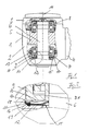
- the head part 1 shown in Fig. 1 of a dental Handpiece comprises a head housing 2 and a cover 3 and a not shown Connection piece to a handle part 4.
- a rotor 5 is attached to a rotor shaft 6, the rotor shaft 6 in a bearing arrangement is rotatably mounted, which consists of two shoulder bearings 7, 8 exists, which are arranged in an X arrangement.
- the bearing 7, 8 comprises an outer bearing ring 9, the has an axial stop surface 10.
- the camp 7 is arranged in a bearing seat 11 of the head housing 2, in which also a corrugated spring 12 as an embodiment is inserted for a spring element.
- resilient ones can also be used O-rings, quad-rings, disc springs or other elastic Rings are used if their spring characteristic the required forces at the given Provides way. The height of the stop judges then after the maximum permissible crushing of the O-ring, without permanent changes in the spring characteristic are to be feared.
- the bearing arrangement described here can be found in the area of the bearing 8 in the lid 3 again accordingly.
- the outer bearing ring is made of an elastically deformable O-ring 13 supported radially against the head housing 2, the outer bearing ring 9 in the direction of the axis of rotation 14 of the rotor is displaceable.
- a bearing surface 15 is present in the bearing receptacle 11, on which the corrugated spring 12 rests.
- On the outside The circumference of the contact surface 15 is a stop 16 arranged, the stop surface 17 opposite the Support surface 15 has a height that is at least the Corresponds to the thickness of the corrugated spring 12 and here approximately is twice the thickness. It is under the thickness the corrugated spring understood the thickness of the material and not the greatest distance between the troughs the wave crests.
- FIG. 2 is an enlargement of the bearing receptacle 11 shown in Fig. 1, in which the outer bearing ring 9 with its axial stop surface 10 is.
- an inner ring 9.1 of the Bearing shown, which sits on the rotor axis 6.
- the corrugated spring 12 is arranged, in this representation just a wave trough rests on the support surface 15. It can still be seen the stop 16 with the stop surface 17 which the bearing ring 10 rests during an axial displacement.
- the stop 16 is shown in the cut Area with an embossing 18 and one formed from displaced material of the impression 18 Provided projection 19, the projection 19 over the top of the wave spring 12 in the trough a piece extends far.
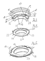
- Fig. 3 and Fig. 4 is a corrugated spring 12 with three Wave valleys 20, 21, 22 and three wave crests 23, 24, 25 shown that captive in a bearing 11 is captured.
- the bearing receptacle 11 points in brought the stop surface 17 of the stop 16 Impressions 18 in the area of the troughs 20, 22, which is a little bit under formation of the radial projection 19 extend over the top of the wave spring 12.
- FIG. 5 is another securing means for the captive Definition of the wave spring 12 in the bearing holder 11 in the form of a retaining ring 26, which in turn has projections 27 which overlap the wave troughs of the wave spring 12 to a certain extent.
- the locking ring 26 can be in the bearing 11 may be trapped.
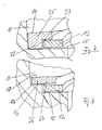
- Embodiments of the locking ring 27 are shown in FIGS. 6 and 7 reproduced.
- the circlip shown in Fig. 6 is in the area of a projection 27 in Section shown. It can be seen that the locking ring 26 on the one in the bearing seat 11 Stop surface 17 of the stop 16 rests, the corrugated spring 12 over the projection 27 a piece is far exceeded.
- the height of the stop surface 17 above the bearing surface 15 corresponds at least to the thickness the corrugated spring and surpasses in the embodiment this thickness, so the corrugated spring with a certain Game is held.
- the stop surface 17 of the stop 16 does not come with the outer bearing ring in contact because this is on the top 17 'of the locking ring 27 rests.
- the retaining ring 26 'shown in FIG. 7 is like this trained that on a stop in the warehouse 11 can be dispensed with. To do this, the locking ring points 26 stroke the corrugated spring 12 on the circumference enclosing over the entire thickness of the corrugated spring Bund 28 on the bearing surface 15 of the bearing 11 rests directly. Above the alliance 28 projections 27 are provided, which the wave spring spill over a bit in the wave valleys.
- FIG. 1 a force-displacement diagram is shown in FIG the spring characteristic of the corrugated spring shown, with the Area I the area of the optimal preload is specified.
- the corrugated spring itself is due to the Stop not flattened, what for the wave spring would constitute a case of overuse. This means the spring characteristic for a long time is retained, which means a long service life. It is essential that for vibration decoupling between Rotor shaft and housing have a soft suspension what is advantageous by the teaching of the invention can be realized.
Landscapes
- Health & Medical Sciences (AREA)
- Oral & Maxillofacial Surgery (AREA)
- General Engineering & Computer Science (AREA)
- Engineering & Computer Science (AREA)
- Epidemiology (AREA)
- Dentistry (AREA)
- Mechanical Engineering (AREA)
- Life Sciences & Earth Sciences (AREA)
- Animal Behavior & Ethology (AREA)
- General Health & Medical Sciences (AREA)
- Public Health (AREA)
- Veterinary Medicine (AREA)
- Support Of The Bearing (AREA)
- Dental Tools And Instruments Or Auxiliary Dental Instruments (AREA)
- Brushes (AREA)
Abstract
Description
- Fig. 1
- ein Kopfteil eines zahnärztlichen Handstücks mit einem mittels einer Lageranordnung drehbar gelagerten Rotor, die
- Fig. 2
- eine Detailansicht einer ersten Ausführungsform für die Erzeugung der Vorspannung mittels einer Wellfeder, die
- Fig. 3
- eine perspektivische Teilansicht auf die Wellfeder gem. Fig. 2, die
- Fig. 4
- eine perspektivische Teilansicht gem. Fig. 3 mit einer vollständigen Wellfeder, die
- Fig. 5
- ein weiteres Ausführungsbeispiel mit einer durch einen Sicherungsring gehaltenen Wellfeder, die
- Fig. 6
- der Teilansicht einer Ausgestaltung des Sicherungsrings gemäß Fig. 5, die
- Fig. 7
- eine weitere Ausgestaltung des Sicherungsrings gemäß Fig. 5 und die
- Fig. 8
- ein Diagramm über den Kraft-Wegverlauf mit einem optimalen Arbeitsbereich für die Wellfeder.
Claims (12)
- Zahnärztliches Handstück, aufweisend ein Kopfteil (1) mit einem mittels einer Lageranordnung drehbar gelagerten Rotor (5), dadurch gekennzeichnet, daß die Lageranordnung einen äußeren Lagerring (9) umfaßt, der eine axiale Anschlagfläche (10) aufweist, daß eine Lageraufnahme (11) des äußeren Lagerrings (9) eine Auflagefläche (15) aufweist, auf der ein Federelement, vorzugsweise eine Wellfeder (12) aufliegt, wobei das Federelement (12) mit der axialen Anschlagfläche (10) des äußeren Lagerrings (9) zusammenwirkt, und daß im Bereich der Auflagefläche (15) am äußeren Umfang ein Anschlag (16) angeordnet ist, dessen Anschlagsfläche (17) gegenüber der Auflagefläche (15) eine Höhe aufweist, die mindestens der kleinsten zulässigen Dicke des Federelements (12) entspricht.
- Zahnärztliches Handstück nach Anspruch 1, dadurch gekennzeichnet, daß im Bereich der Lageraufnahme (11) Sicherungsmittel für das Federelement (12) angeordnet sind, die ein Herausfallen des Federelements (12) verhindern.
- Zahnärztliches Handstück nach Anspruch 1 oder 2, dadurch gekennzeichnet, daß das Federelement (12) durch unmittelbaren oder mittelbaren axialen Formschluss mit dem Gehäuse gesichert ist.
- Zahnärztliches Handstück nach Anspruch 3, dadurch gekennzeichnet, daß die Sicherungsmittel Radialvorsprünge (19; 27) aufweisen, die das Federelement (12) zumindest ein Stück weit übergreifen.
- Zahnärztliches Handstück nach einem der Ansprüche 1 bis 4, dadurch gekennzeichnet, daß die Radialvorsprünge (19) durch bereichsweises Umformen eines in der Lageraufnahme angeordneten Anschlags (16) gebildet ist.
- Zahnärztliches Handstück nach einem der Ansprüche 1 bis 5, dadurch gekennzeichnet, daß die Höhe des Anschlags der Lageraufnahme derart bestimmt ist, daß das Federelement (12) im Bereich der optimalen Lagervorspannung betrieben wird, wobei die axiale Beweglichkeit des Lagerrings entsprechend begrenzt ist.
- Zahnärztliches Handstück nach einem der Ansprüche 1 bis 6, dadurch gekennzeichnet, daß sowohl im Kopfteil (1) als auch in einem Deckel (3) des Kopfteils ein Federelement (12) angeordnet ist.
- Zahnärztliches Handstück nach einem der Ansprüche 1 bis 7, dadurch gekennzeichnet, daß die Lageranordnung aus zwei Schulterlagern besteht, welche in einer X-Anordnung angeordnet sind, insbesondere aus Kugellagern.
- Zahnärztliches Handstück nach einem der Ansprüche 1 bis 8, dadurch gekennzeichnet, daß der äußere Lagerring (9) über ein Ringelement (13) in radialer Richtung federelastisch gelagert und in axialer Richtung gegen die Federkraft des Federelements (12) verschiebbar ist.
- Zahnärztliches Handstück nach einem der Ansprüche 1 bis 9, dadurch gekennzeichnet, daß das Federelement als Wellfeder ausgebildet ist, die vorzugsweise mindestens drei Wellentäler (20, 21, 22) aufweist.
- Zahnärztliches Handstück nach Anspruch 10, dadurch gekennzeichnet, dass die Wellfeder (12) in den Wellentälern (20, 21, 22) gesichert ist.
- Zahnärztliches Handstück nach Anspruch 10 oder 11, dadurch gekennzeichnet, dass die Sicherungsmittel Radialvorsprünge (19; 27) aufweisen, die entsprechend der auf der Auflagefläche der Lageraufnahme (11) aufliegenden Wellentäler der Wellfeder (12) über den Umfang verteilt angeordnet sind.
Applications Claiming Priority (2)
| Application Number | Priority Date | Filing Date | Title |
|---|---|---|---|
| DE10025416 | 2000-05-24 | ||
| DE10025416A DE10025416A1 (de) | 2000-05-24 | 2000-05-24 | Zahnärztliches Handstück mit einem drehbar gelagerten Rotor |
Publications (2)
| Publication Number | Publication Date |
|---|---|
| EP1157671A1 true EP1157671A1 (de) | 2001-11-28 |
| EP1157671B1 EP1157671B1 (de) | 2006-11-22 |
Family
ID=7643185
Family Applications (1)
| Application Number | Title | Priority Date | Filing Date |
|---|---|---|---|
| EP01112528A Expired - Lifetime EP1157671B1 (de) | 2000-05-24 | 2001-05-23 | Zahnärztliches Handstück mit einem drehbar gelagerten Rotor |
Country Status (3)
| Country | Link |
|---|---|
| EP (1) | EP1157671B1 (de) |
| AT (1) | ATE345745T1 (de) |
| DE (2) | DE10025416A1 (de) |
Cited By (1)
| Publication number | Priority date | Publication date | Assignee | Title |
|---|---|---|---|---|
| EP1985245A1 (de) * | 2007-04-23 | 2008-10-29 | W & H Dentlwerk Bürmoos GmbH | Medizinisches Handgriffelement |
Families Citing this family (1)
| Publication number | Priority date | Publication date | Assignee | Title |
|---|---|---|---|---|
| DE102012205275A1 (de) | 2012-03-30 | 2013-10-02 | Sirona Dental Systems Gmbh | Zahnärztliches Handstück mit Wälzlager |
Citations (4)
| Publication number | Priority date | Publication date | Assignee | Title |
|---|---|---|---|---|
| US3376084A (en) * | 1965-01-07 | 1968-04-02 | Barden Corp | Dental handpiece |
| US4219330A (en) * | 1978-09-20 | 1980-08-26 | American Hospital Supply Corporation | Dental handpiece and rotor cartridge replacement assembly therefor |
| US4249896A (en) * | 1978-09-29 | 1981-02-10 | Syntex (U.S.A.) Inc. | Compliantly mountable turbine cartridge assembly for gas-driven dental handpiece |
| US5676542A (en) * | 1994-07-01 | 1997-10-14 | Kaltenbach & Voigt Gmbh & Co. | Medical or dental treatment instrument |
-
2000
- 2000-05-24 DE DE10025416A patent/DE10025416A1/de not_active Withdrawn
-
2001
- 2001-05-23 DE DE50111483T patent/DE50111483D1/de not_active Expired - Lifetime
- 2001-05-23 AT AT01112528T patent/ATE345745T1/de active
- 2001-05-23 EP EP01112528A patent/EP1157671B1/de not_active Expired - Lifetime
Patent Citations (4)
| Publication number | Priority date | Publication date | Assignee | Title |
|---|---|---|---|---|
| US3376084A (en) * | 1965-01-07 | 1968-04-02 | Barden Corp | Dental handpiece |
| US4219330A (en) * | 1978-09-20 | 1980-08-26 | American Hospital Supply Corporation | Dental handpiece and rotor cartridge replacement assembly therefor |
| US4249896A (en) * | 1978-09-29 | 1981-02-10 | Syntex (U.S.A.) Inc. | Compliantly mountable turbine cartridge assembly for gas-driven dental handpiece |
| US5676542A (en) * | 1994-07-01 | 1997-10-14 | Kaltenbach & Voigt Gmbh & Co. | Medical or dental treatment instrument |
Cited By (1)
| Publication number | Priority date | Publication date | Assignee | Title |
|---|---|---|---|---|
| EP1985245A1 (de) * | 2007-04-23 | 2008-10-29 | W & H Dentlwerk Bürmoos GmbH | Medizinisches Handgriffelement |
Also Published As
| Publication number | Publication date |
|---|---|
| EP1157671B1 (de) | 2006-11-22 |
| DE50111483D1 (de) | 2007-01-04 |
| ATE345745T1 (de) | 2006-12-15 |
| DE10025416A1 (de) | 2001-12-06 |
Similar Documents
| Publication | Publication Date | Title |
|---|---|---|
| EP0840024B1 (de) | Gedämpftes Wälzlager | |
| DE2312395C2 (de) | Vorrichtung zum Auffangen des Axialspiels in einem Schneckengetriebe | |
| DE69202351T2 (de) | Schwingungsdämpfende Lagervorrichtung. | |
| DE2456571C3 (de) | Kugelgelenk | |
| DE102008056024A1 (de) | Lageranordnung | |
| DE10007437B4 (de) | Verfahren zur Fixierung wenigstens eines Lagers in einer Lageraufnahme und damit hergestellte Lageranordnung | |
| DE4126317A1 (de) | Lageranordnung mit variabler vorspannung | |
| DE947126C (de) | Schwingungsgedaempftes elastisches Lager | |
| DE2417068C3 (de) | Schwenkvorrichtung fur die Welle eines Uhrteiles | |
| DE102007023456A1 (de) | Lageranordnung | |
| DE102004048720A1 (de) | Kugellager, insbesondere zur Lagerung der Hauptspindel einer Werkzeugmaschine | |
| DE102021206865A1 (de) | Flüssigkeitspumpe | |
| DE3309792C2 (de) | Lager für die Kurbelwelle der Brennkraftmaschine eines Kraftfahrzeuges | |
| DE1775668C3 (de) | Winkelbewegliche Steckkupplung | |
| DE3832543A1 (de) | Lager fuer die elastische lagerung einer welle, insbesondere mittellager fuer die gelenkwelle eines fahrzeugantriebs | |
| EP1157671A1 (de) | Zahnärztliches Handstück mit einem drehbar gelagerten Rotor | |
| DE2718659A1 (de) | Wellendichtring | |
| DE19942840A1 (de) | Entkopplungsvorrichtung für Aktuatoren | |
| DE3716098A1 (de) | Antriebsvorrichtung fuer pumpen oder dgl. | |
| DE4330367B4 (de) | Vorrichtung zum motorischen Längsverstellen eines Sitzes in einem Kraftfahrzeug | |
| DE102017209613A1 (de) | Dentales Hand- oder Winkelstück mit einem rotierenden Werkzeug | |
| EP1136346B1 (de) | Verbindungselement für eine elastische Verbindung zweier Bauteile | |
| DE1264306B (de) | Spinn- oder Zwirnspindel | |
| DE3721757C2 (de) | ||
| DE102006055220B4 (de) | Kraftübertragungsaggregat mit zwei drehbaren Bauteilen |
Legal Events
| Date | Code | Title | Description |
|---|---|---|---|
| PUAI | Public reference made under article 153(3) epc to a published international application that has entered the european phase |
Free format text: ORIGINAL CODE: 0009012 |
|
| AK | Designated contracting states |
Kind code of ref document: A1 Designated state(s): AT BE CH CY DE DK ES FI FR GB GR IE IT LI LU MC NL PT SE TR |
|
| AX | Request for extension of the european patent |
Free format text: AL;LT;LV;MK;RO;SI |
|
| 17P | Request for examination filed |
Effective date: 20020503 |
|
| AKX | Designation fees paid |
Free format text: AT BE CH CY DE DK ES FI FR GB GR IE IT LI LU MC NL PT SE TR |
|
| 17Q | First examination report despatched |
Effective date: 20050606 |
|
| GRAP | Despatch of communication of intention to grant a patent |
Free format text: ORIGINAL CODE: EPIDOSNIGR1 |
|
| GRAS | Grant fee paid |
Free format text: ORIGINAL CODE: EPIDOSNIGR3 |
|
| GRAA | (expected) grant |
Free format text: ORIGINAL CODE: 0009210 |
|
| AK | Designated contracting states |
Kind code of ref document: B1 Designated state(s): AT BE CH CY DE DK ES FI FR GB GR IE IT LI LU MC NL PT SE TR |
|
| PG25 | Lapsed in a contracting state [announced via postgrant information from national office to epo] |
Ref country code: IE Free format text: LAPSE BECAUSE OF FAILURE TO SUBMIT A TRANSLATION OF THE DESCRIPTION OR TO PAY THE FEE WITHIN THE PRESCRIBED TIME-LIMIT Effective date: 20061122 Ref country code: FI Free format text: LAPSE BECAUSE OF FAILURE TO SUBMIT A TRANSLATION OF THE DESCRIPTION OR TO PAY THE FEE WITHIN THE PRESCRIBED TIME-LIMIT Effective date: 20061122 Ref country code: NL Free format text: LAPSE BECAUSE OF FAILURE TO SUBMIT A TRANSLATION OF THE DESCRIPTION OR TO PAY THE FEE WITHIN THE PRESCRIBED TIME-LIMIT Effective date: 20061122 |
|
| REG | Reference to a national code |
Ref country code: GB Ref legal event code: FG4D Free format text: NOT ENGLISH |
|
| REG | Reference to a national code |
Ref country code: CH Ref legal event code: EP |
|
| REG | Reference to a national code |
Ref country code: IE Ref legal event code: FG4D Free format text: LANGUAGE OF EP DOCUMENT: GERMAN Ref country code: CH Ref legal event code: NV Representative=s name: WILLIAM BLANC & CIE CONSEILS EN PROPRIETE INDUSTRI |
|
| REF | Corresponds to: |
Ref document number: 50111483 Country of ref document: DE Date of ref document: 20070104 Kind code of ref document: P |
|
| PG25 | Lapsed in a contracting state [announced via postgrant information from national office to epo] |
Ref country code: SE Free format text: LAPSE BECAUSE OF FAILURE TO SUBMIT A TRANSLATION OF THE DESCRIPTION OR TO PAY THE FEE WITHIN THE PRESCRIBED TIME-LIMIT Effective date: 20070222 Ref country code: DK Free format text: LAPSE BECAUSE OF FAILURE TO SUBMIT A TRANSLATION OF THE DESCRIPTION OR TO PAY THE FEE WITHIN THE PRESCRIBED TIME-LIMIT Effective date: 20070222 |
|
| PG25 | Lapsed in a contracting state [announced via postgrant information from national office to epo] |
Ref country code: ES Free format text: LAPSE BECAUSE OF FAILURE TO SUBMIT A TRANSLATION OF THE DESCRIPTION OR TO PAY THE FEE WITHIN THE PRESCRIBED TIME-LIMIT Effective date: 20070305 |
|
| PG25 | Lapsed in a contracting state [announced via postgrant information from national office to epo] |
Ref country code: PT Free format text: LAPSE BECAUSE OF FAILURE TO SUBMIT A TRANSLATION OF THE DESCRIPTION OR TO PAY THE FEE WITHIN THE PRESCRIBED TIME-LIMIT Effective date: 20070423 |
|
| NLV1 | Nl: lapsed or annulled due to failure to fulfill the requirements of art. 29p and 29m of the patents act | ||
| GBV | Gb: ep patent (uk) treated as always having been void in accordance with gb section 77(7)/1977 [no translation filed] |
Effective date: 20061122 |
|
| REG | Reference to a national code |
Ref country code: IE Ref legal event code: FD4D |
|
| EN | Fr: translation not filed | ||
| PLBE | No opposition filed within time limit |
Free format text: ORIGINAL CODE: 0009261 |
|
| STAA | Information on the status of an ep patent application or granted ep patent |
Free format text: STATUS: NO OPPOSITION FILED WITHIN TIME LIMIT |
|
| 26N | No opposition filed |
Effective date: 20070823 |
|
| PG25 | Lapsed in a contracting state [announced via postgrant information from national office to epo] |
Ref country code: GB Free format text: LAPSE BECAUSE OF FAILURE TO SUBMIT A TRANSLATION OF THE DESCRIPTION OR TO PAY THE FEE WITHIN THE PRESCRIBED TIME-LIMIT Effective date: 20061122 |
|
| BERE | Be: lapsed |
Owner name: SIRONA DENTAL SYSTEMS G.M.B.H. Effective date: 20070531 |
|
| PG25 | Lapsed in a contracting state [announced via postgrant information from national office to epo] |
Ref country code: MC Free format text: LAPSE BECAUSE OF NON-PAYMENT OF DUE FEES Effective date: 20070531 |
|
| PG25 | Lapsed in a contracting state [announced via postgrant information from national office to epo] |
Ref country code: BE Free format text: LAPSE BECAUSE OF NON-PAYMENT OF DUE FEES Effective date: 20070531 |
|
| PG25 | Lapsed in a contracting state [announced via postgrant information from national office to epo] |
Ref country code: FR Free format text: LAPSE BECAUSE OF FAILURE TO SUBMIT A TRANSLATION OF THE DESCRIPTION OR TO PAY THE FEE WITHIN THE PRESCRIBED TIME-LIMIT Effective date: 20070713 Ref country code: GR Free format text: LAPSE BECAUSE OF FAILURE TO SUBMIT A TRANSLATION OF THE DESCRIPTION OR TO PAY THE FEE WITHIN THE PRESCRIBED TIME-LIMIT Effective date: 20070223 |
|
| PG25 | Lapsed in a contracting state [announced via postgrant information from national office to epo] |
Ref country code: FR Free format text: LAPSE BECAUSE OF FAILURE TO SUBMIT A TRANSLATION OF THE DESCRIPTION OR TO PAY THE FEE WITHIN THE PRESCRIBED TIME-LIMIT Effective date: 20061122 |
|
| PG25 | Lapsed in a contracting state [announced via postgrant information from national office to epo] |
Ref country code: CY Free format text: LAPSE BECAUSE OF FAILURE TO SUBMIT A TRANSLATION OF THE DESCRIPTION OR TO PAY THE FEE WITHIN THE PRESCRIBED TIME-LIMIT Effective date: 20061122 Ref country code: LU Free format text: LAPSE BECAUSE OF NON-PAYMENT OF DUE FEES Effective date: 20070523 |
|
| PG25 | Lapsed in a contracting state [announced via postgrant information from national office to epo] |
Ref country code: TR Free format text: LAPSE BECAUSE OF FAILURE TO SUBMIT A TRANSLATION OF THE DESCRIPTION OR TO PAY THE FEE WITHIN THE PRESCRIBED TIME-LIMIT Effective date: 20061122 |
|
| REG | Reference to a national code |
Ref country code: CH Ref legal event code: PFA Owner name: SIRONA DENTAL SYSTEMS GMBH Free format text: SIRONA DENTAL SYSTEMS GMBH#FABRIKSTRASSE 31#64625 BENSHEIM (DE) -TRANSFER TO- SIRONA DENTAL SYSTEMS GMBH#FABRIKSTRASSE 31#64625 BENSHEIM (DE) |
|
| REG | Reference to a national code |
Ref country code: CH Ref legal event code: PCAR Free format text: NOVAGRAAF SWITZERLAND SA;CHEMIN DE L'ECHO 3;1213 ONEX (CH) |
|
| PGFP | Annual fee paid to national office [announced via postgrant information from national office to epo] |
Ref country code: CH Payment date: 20200515 Year of fee payment: 20 |
|
| REG | Reference to a national code |
Ref country code: DE Ref legal event code: R082 Ref document number: 50111483 Country of ref document: DE |
|
| PGFP | Annual fee paid to national office [announced via postgrant information from national office to epo] |
Ref country code: IT Payment date: 20200414 Year of fee payment: 20 |
|
| PGFP | Annual fee paid to national office [announced via postgrant information from national office to epo] |
Ref country code: AT Payment date: 20200428 Year of fee payment: 20 |
|
| PGFP | Annual fee paid to national office [announced via postgrant information from national office to epo] |
Ref country code: DE Payment date: 20200512 Year of fee payment: 20 |
|
| REG | Reference to a national code |
Ref country code: DE Ref legal event code: R071 Ref document number: 50111483 Country of ref document: DE |
|
| REG | Reference to a national code |
Ref country code: CH Ref legal event code: PL |
|
| REG | Reference to a national code |
Ref country code: AT Ref legal event code: MK07 Ref document number: 345745 Country of ref document: AT Kind code of ref document: T Effective date: 20210523 |