EP1156586B1 - Analog-Digital-Wandler nach dem Fliessbandverfahren mit Rauschformung - Google Patents
Analog-Digital-Wandler nach dem Fliessbandverfahren mit Rauschformung Download PDFInfo
- Publication number
- EP1156586B1 EP1156586B1 EP01401228A EP01401228A EP1156586B1 EP 1156586 B1 EP1156586 B1 EP 1156586B1 EP 01401228 A EP01401228 A EP 01401228A EP 01401228 A EP01401228 A EP 01401228A EP 1156586 B1 EP1156586 B1 EP 1156586B1
- Authority
- EP
- European Patent Office
- Prior art keywords
- signal
- digital
- delta
- analogue
- digitized
- Prior art date
- Legal status (The legal status is an assumption and is not a legal conclusion. Google has not performed a legal analysis and makes no representation as to the accuracy of the status listed.)
- Expired - Lifetime
Links
Images
Classifications
-
- H—ELECTRICITY
- H03—ELECTRONIC CIRCUITRY
- H03M—CODING; DECODING; CODE CONVERSION IN GENERAL
- H03M3/00—Conversion of analogue values to or from differential modulation
- H03M3/30—Delta-sigma modulation
- H03M3/458—Analogue/digital converters using delta-sigma modulation as an intermediate step
- H03M3/46—Analogue/digital converters using delta-sigma modulation as an intermediate step using a combination of at least one delta-sigma modulator in series with at least one analogue/digital converter of a different type
-
- H—ELECTRICITY
- H03—ELECTRONIC CIRCUITRY
- H03M—CODING; DECODING; CODE CONVERSION IN GENERAL
- H03M1/00—Analogue/digital conversion; Digital/analogue conversion
- H03M1/12—Analogue/digital converters
- H03M1/14—Conversion in steps with each step involving the same or a different conversion means and delivering more than one bit
- H03M1/16—Conversion in steps with each step involving the same or a different conversion means and delivering more than one bit with scale factor modification, i.e. by changing the amplification between the steps
- H03M1/164—Conversion in steps with each step involving the same or a different conversion means and delivering more than one bit with scale factor modification, i.e. by changing the amplification between the steps the steps being performed sequentially in series-connected stages
Definitions
- the invention relates to analog-to-digital converters.
- the analog-to-digital converters are divided into two large families: broadband ADCs (some MHz) with a resolution average (up to 10 effective bits), and NAC narrowband (a few kHz) and high resolution (up to 16 bits and more).
- Pipeline analog-to-digital conversion and ⁇ modulation are part of the many techniques known in the field of analog-to-digital conversion.
- CAN pipeline generally has a bandwidth (a few MHz) and an average resolution: the order of 8 to 10 effective bits.
- ⁇ modulators are used to convert signals with high resolution (up to 16 bits and more), but on a generally narrow frequency band (some kHz).
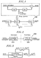
- the pipeline converter consists of conversion stages analog-digital elementary which are arranged in pipeline. Each pipeline stage provides a number of bits that contributes to coding digital signal.
- the operating principle of the pipeline stage involves digitizing the input signal on a small number of bits at means of a flash type converter. Then this numeric code is reconstructed into an analog signal before subtracting it from the input signal (see Figure 1). The resulting signal is called the residue.
- Each floor pipeline treats the residue from the previous stage (except the first floor that receives the input signal) and delivers a new residue to the next stage.
- the delta-sigma analog-to-digital converter consists of a delta-sigma modulator followed by a decimator.
- the delta-sigma modulator oversamples the input signal and rejects the quantization noise outside the useful band.
- the decimator filters in the digital domain the quantization noise formatted and brings back the output rate of the output signal at the frequency of Nyquist.
- delta-sigma modulation makes it possible to reach high performance.
- the conversion band is usually limited to a few kilohertz.
- WO 00/08765 discloses a delta-sigma modulator suitable for analog / digital converters with large bandwidth and high resolution.
- the object of the present invention is to propose a converter analog / digital which has a significant resolution on a band of chosen frequency while leaving an acceptable performance outside of this chosen band.
- a converter analog / digital including a first module of the type having a series stages of treatment, these treatment stages each carrying two first analog / digital and then digital / analog conversions from the output signal from the previous stage and then a signal subtraction as well obtained at the output signal of the previous stage to thereby provide the signal analog output of said stage, said first module further comprising means for assembling the digitized signals by each stage so to form a digital signal that represents in numerical form the input signal of the converter, characterized in that the converter further includes a modulator that digitizes the output signal of a said stages as well as means for subtracting the signal as well digitized to said assembled digital signal.
- the invention also proposes for this purpose a method for producing an analog / digital conversion of an input signal into a signal of output in which a series of processing steps is performed in which we realize, in each, two conversions first analog / digital then digital / analog of a signal-result of the previous step and then a subtraction of the analog signal thus obtained to the result signal of the previous step to thus provide the result signal of the considered step, in which process the signals are assembled.
- digitized at each step to form a digital signal that represents in digital form the input signal, characterized in that that the result signal of one of said steps is further digitized by means of of a delta-sigma modulator and subtract this digitized signal from said signal assembled digital.
- the proposed system uses a delta-sigma modulator 210.
- This modulator 210 increases the performance of the pipeline 100 to a portion of its conversion band.
- the characteristics of the delta-sigma 210 modulator used are condition both the performance gain, the width of the band of increased performance conversion, and the total complexity of the system offers.
- the signal b N (nT) delivered by the delta-sigma modulator 210 consists of the digitized signal b (nT) multiplied by a transfer function of the signal STF (nT) and a new quantization noise q (nT) multiplied by an NTF formatting function (nT) specific to the delta-sigma modulator 210 used.
- a ⁇ modulator includes two functions of transfer, one which is seen by the input signal of the modulator, the other which is seen by the quantization noise (noise shaping function NTF (nT)).
- a module 150 applies a transfer function that is the same as the function seen by the input signal of modulator ⁇ 210.
- the module 150 Before subtracting the signal b N (nT) to s N (nT), the module 150 thus multiplies the latter by the transfer function STF (nT) specific to the delta-sigma modulator.
- the new digital signal obtained with the proposed system consists of the image of the input signal on which is superimposed a noise of power quantization which is lower in a frequency band data.
- the performances of the CAN are then increased, but on a reduced conversion band by the use of delta-sigma modulation (formatting the quantization noise).
- a digital decimation filter 220 is then necessary to suppress the quantization noise rejected in outside the conversion band.
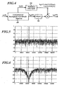
- the proposed system was modeled and simulated on a processing tool of the signal. To validate the original idea, an analog-digital converter 8-bit pipeline 100 and a delta-sigma 210 bandpass modulator 1 bit of order 4 were chosen. The working frequency is 40 MHz. The proposed system is tested by applying a sinusoidal signal of 6.7 MHz frequency.
- Figure 5 shows the output signal of the 8-bit CAN pipeline 100 (conventional operation) on a 20 MHz conversion band.
- the performance of the CAN 100 in terms of signal-to-noise ratio (SNR) are 50 dB (8 bits) on a 20 MHz band and 70 dB (almost 12 bits) effective) on a 200 kHz band around the signal (6.58 - 6.78 MHz).
- Figure 6 shows the output signal of the proposed system (optimized operation) on a 20 MHz band.
- the signal-to-noise ratio is 109 dB (about 18 effective bits).
- the proposed system therefore makes it possible to increase the performance of a pipeline analog-to-digital converter on a frequency band given through the use of a delta-sigma modulator (and a function digital signal processing). This last digitizes the residue of the last Pipeline stage with high accuracy to reduce the noise power quantization in a given frequency band.
- a wide conversion band is required, shown in the figures are provided to disable the delta-sigma modulator 210 (such means are for example a simple switch), the CAN then operating classically in its pipeline mode.
- the proposed system allows more generally to optimize the performance of the CAN around a useful band chosen, by connecting on the CAN pipeline a delta-sigma modulator adapted, for example by connecting using connection means conventional, a low-pass delta-sigma modulator or bandpass according to the need.
- Such a possibility of choice of the delta sigma modulator exists not only at the stage of manufacture of the device but also in use in the case of such a device provided with several modulators and switching means to choose which of these modulators that is associated with CAN pipeline.
- Such a system is particularly suitable for multi-mode communication where the components used in the chain of reception must be reconfigured according to the chosen application in order to share material resources.
- Such terminals are in particular used in telecommunications by radio waves, particularly in the field of the telephone.
Claims (9)
- Analog/Digital-Wandler, der ein erstes Modul (100) der Bauart umfaßt, die eine Reihe von Verarbeitungsstufen aufweist, wobei jede dieser Verarbeitungsstufen folgendes durchführt: zwei Umwandlungen, zuerst analog/digital, dann digital/analog des Ausgangssignals der vorhergehenden Stufe, anschließend eine Subtraktion des so erhaltenen Signals vom Ausgangssignal der vorhergehenden Stufe, um damit das analoge Ausgangssignal der Stufe bereitzustellen, wobei das erste Modul (100) außerdem Mittel zum Zusammensetzen der von allen Stufen (S1 ..., Si) digitalisierten Signale umfaßt, um ein digitales Signal (sN(nT)) zu bilden, das in digitaler Form das Eingangssignal (e(nT)) des Wandlers repräsentiert, dadurch gekennzeichnet, daß der Wandler außerdem einen Delta-Sigma-Modulator (210), der das Ausgangssignal (b(nT)) einer der Stufen digitalisiert, sowie Mittel zur Subtraktion des so digitalisierten Signals vom zusammengesetzten digitalen Signal (sN(nT)) umfaßt.
- Wandler nach Anspruch 1, dadurch gekennzeichnet, daß die Mittel zum Subtrahieren des so digitalisierten Signals vom zusammengesetzten digitalen Signal (SN(nT)) Mittel (150) umfassen, die auf das zusammengesetzte Signal eine Verarbeitung anwenden, die der Übertragungsfunktion (STF(nT)) des ΔΣ-Modulators (210), die auf das Eingangssignal dieses ΔΣ-Modulators angewendet wird, entspricht.
- Wandler nach Anspruch 1 oder Anspruch 2, dadurch gekennzeichnet, daß der Delta-Sigma-Modulator (200) am Ausgang der letzten Stufe des ersten Moduls (100) angeordnet ist.
- Wandler nach einem der vorhergehenden Ansprüche, dadurch gekennzeichnet, daß er Mittel zum Abschalten des Delta-Sigma-Modulators (210) umfaßt.
- Wandler nach einem der vorhergehenden Ansprüche, dadurch gekennzeichnet, daß er folgendes umfaßt: mehrere Delta-Sigma-Modulatoren (210), von denen jeder dafür geeignet ist, das Ausgangssignal einer der Stufen zu digitalisieren, und Schaltmittel zum Einschalten eines Delta-Sigma-Modulators, der unter diesen Delta-Sigma-Modulatoren (210) ausgewählt ist.
- Wandler nach einem der vorhergehenden Ansprüche, dadurch gekennzeichnet, daß er einen Dezimationsfilter (220) umfaßt, der nach den Mitteln zum Zusammensetzen der von jeder Stufe digitalisierten Signale angeordnet ist.
- Kommunikationseinrichtung, die Mittel zur Auswahl eines Frequenzbands zum Senden oder Empfangen von Signalen umfaßt, dadurch gekennzeichnet, daß sie einen Wandler nach einem der vorhergehenden Ansprüche umfaßt.
- Verfahren zur Durchführung einer Analog/Digital-Wandlung eines Eingangssignals (e(nT)) in ein Ausgangssignal (yN(nT)), in dem eine Folge von Verarbeitungsschritten ausgeführt wird, wobei in jedem folgendes ausgeführt wird: zwei Umwandlungen, zuerst analog/digital, dann digital/analog eines Ausgangssignals des vorhergehenden Schrittes, anschließend eine Subtraktion des so erhaltenen analogen Signals vom Ausgangssignal des vorhergehenden Schrittes, um damit das Signalergebnis des betrachteten Schrittes bereitzustellen, wobei in diesem Verfahren die in allen Schritten (S1 ..., Si) digitalisierten Signale zusammengesetzt werden, um ein digitales Signal (sN(nT)) zu bilden, das in digitaler Form das Eingangssignal (e(nT)) repräsentiert, dadurch gekennzeichnet, daß außerdem das Signalergebnis eines der Schritte (b(nT)) mittels eines Delta-Sigma-Modulators (210) digitalisiert und dieses digitalisierte Signal (bN(nT)) vom zusammengesetzten digitalen Signal (sN(nT)) subtrahiert wird.
- Verfahren nach Anspruch 8, dadurch gekennzeichnet, daß auf das zusammengesetzte Signal (SN(nT)) eine Verarbeitung angewendet wird (150), die der Übertragungsfunktion (STF(nT)) des Delta-Sigma-Modulators (210), die auf das Eingangssignal dieses ΔΣ-Modulators (210) angewendet wird, entspricht.
Applications Claiming Priority (2)
| Application Number | Priority Date | Filing Date | Title |
|---|---|---|---|
| FR0006198 | 2000-05-16 | ||
| FR0006198A FR2809247A1 (fr) | 2000-05-16 | 2000-05-16 | Convertisseur analogique-numerique pipeline avec mise en forme de bruit |
Publications (2)
| Publication Number | Publication Date |
|---|---|
| EP1156586A1 EP1156586A1 (de) | 2001-11-21 |
| EP1156586B1 true EP1156586B1 (de) | 2005-09-07 |
Family
ID=8850256
Family Applications (1)
| Application Number | Title | Priority Date | Filing Date |
|---|---|---|---|
| EP01401228A Expired - Lifetime EP1156586B1 (de) | 2000-05-16 | 2001-05-14 | Analog-Digital-Wandler nach dem Fliessbandverfahren mit Rauschformung |
Country Status (4)
| Country | Link |
|---|---|
| US (1) | US6507305B2 (de) |
| EP (1) | EP1156586B1 (de) |
| DE (1) | DE60113183D1 (de) |
| FR (1) | FR2809247A1 (de) |
Families Citing this family (5)
| Publication number | Priority date | Publication date | Assignee | Title |
|---|---|---|---|---|
| US7034730B2 (en) * | 2003-10-03 | 2006-04-25 | Wright State University | Pipelined delta sigma modulator analog to digital converter |
| EP1560337A1 (de) * | 2004-01-27 | 2005-08-03 | Infineon Technologies AG | Analog-digital Wandler mit einem Sigma-Delta-Modulator |
| TWI227071B (en) * | 2004-04-13 | 2005-01-21 | Realtek Semiconductor Corp | Pipeline ADC calibrating method utilizing extra ADC module and apparatus thereof |
| US10536161B1 (en) | 2018-10-08 | 2020-01-14 | Analog Devices, Inc. | Noise shaping pipeline analog to digital converters |
| US11038515B2 (en) | 2019-05-13 | 2021-06-15 | Analog Devices, Inc. | Noise shaping algorithmic analog-to-digital converter |
Family Cites Families (13)
| Publication number | Priority date | Publication date | Assignee | Title |
|---|---|---|---|---|
| US4684924A (en) * | 1982-09-30 | 1987-08-04 | Wood Lawson A | Analog/digital converter using remainder signals |
| JP2543095B2 (ja) * | 1987-09-14 | 1996-10-16 | 松下電器産業株式会社 | オ―バ―サンプリング型d/a変換器 |
| US4894657A (en) * | 1988-11-25 | 1990-01-16 | General Electric Company | Pipelined analog-to-digital architecture with parallel-autozero analog signal processing |
| US5043732A (en) * | 1989-09-26 | 1991-08-27 | Analog Devices, Inc. | Analog-to-digital converter employing a pipeline multi-stage architecture |
| NL9001440A (nl) * | 1990-06-22 | 1992-01-16 | Philips Nv | Analoog/digitaal signaal-omvormer met meervoudige sigma-delta modulator. |
| US5181032A (en) * | 1991-09-09 | 1993-01-19 | General Electric Company | High-order, plural-bit-quantization sigma-delta modulators using single-bit digital-to-analog conversion feedback |
| US5742246A (en) * | 1996-03-22 | 1998-04-21 | National Science Council | Stabilizing mechanism for sigma-delta modulator |
| SE516675C2 (sv) * | 1996-05-07 | 2002-02-12 | Ericsson Telefon Ab L M | Förfarande och anordning för att omvandla en analog ström till en digital signal |
| US5771012A (en) * | 1996-09-11 | 1998-06-23 | Harris Corporation | Integrated circuit analog-to-digital converter and associated calibration method and apparatus |
| US5838272A (en) * | 1997-04-17 | 1998-11-17 | President And Fellows Of Harvard College | Error correcting sigma-delta modulation decoding |
| US6166675A (en) * | 1997-09-03 | 2000-12-26 | Texas Instruments Incorporated | Pipeline analog-to-digital conversion system using double sampling and method of operation |
| WO2000008765A2 (en) * | 1998-08-06 | 2000-02-17 | Steensgaard Madsen Jesper | Delta-sigma a/d converter |
| US6285309B1 (en) * | 1999-09-14 | 2001-09-04 | Texas Instruments Incorporated | Nested pipelined analog-to-digital converter |
-
2000
- 2000-05-16 FR FR0006198A patent/FR2809247A1/fr active Pending
-
2001
- 2001-05-14 EP EP01401228A patent/EP1156586B1/de not_active Expired - Lifetime
- 2001-05-14 DE DE60113183T patent/DE60113183D1/de not_active Expired - Lifetime
- 2001-05-16 US US09/855,746 patent/US6507305B2/en not_active Expired - Lifetime
Also Published As
| Publication number | Publication date |
|---|---|
| US6507305B2 (en) | 2003-01-14 |
| FR2809247A1 (fr) | 2001-11-23 |
| EP1156586A1 (de) | 2001-11-21 |
| DE60113183D1 (de) | 2005-10-13 |
| US20020024459A1 (en) | 2002-02-28 |
Similar Documents
| Publication | Publication Date | Title |
|---|---|---|
| US7576671B2 (en) | Mismatch-shaping dynamic element matching systems and methods for multi-bit sigma-delta data converters | |
| JP3100105B2 (ja) | 中間周波数デジタル受信器及び該受信器で実施されるベースバンド濾波方法 | |
| JP4261585B2 (ja) | デルタシグマ・アナログデジタル変換器 | |
| US7304592B2 (en) | Method of adding a dither signal in output to the last integrator of a sigma-delta converter and relative sigma-delta converter | |
| US6922161B2 (en) | Delta-Sigma modulator for reducing quantization noise and oversampling ratio (OSR) | |
| US6326911B1 (en) | Method and apparatus for dithering idle channel tones in delta-sigma analog-to-digital converters | |
| JPH0797749B2 (ja) | アナログ・デイジタル変換器のデルタ・シグマ変調回路 | |
| EP2360839A1 (de) | Zeitkontinuierlicher Analog-Digital-Wandler | |
| FR2765419A1 (fr) | Dispositif de generation de signaux analogiques a partir de convertisseurs analogique-numerique, notamment pour la synthese numerique directe | |
| US6940438B2 (en) | Method and circuit for reducing quantizer input/output swing in a sigma-delta modulator | |
| EP1156586B1 (de) | Analog-Digital-Wandler nach dem Fliessbandverfahren mit Rauschformung | |
| FR3105897A1 (fr) | Dispositif de conversion analogique-numérique comprenant deux étages cascadés de conversion analogique-numérique avec registre à approximations successives et mise en forme du bruit, et capteur électronique associé | |
| CA2450702A1 (fr) | Convertisseur analogique-numerique sigma-delta passe-bande et convertisseur sigma-delta mash l'incorporant | |
| EP3276833A1 (de) | Sigma-delta-wandler mit hoher linearität | |
| WO2001001578A1 (fr) | Procede et systeme de compensation de la non-linearite d'un convertisseur analogique-numerique sigma-delta | |
| FR2911455A1 (fr) | Procede de traitement d'un signal numerique au sein d'un modulateur delta-sigma numerique, et modulateur delta-sigma correspondant | |
| EP1678832B1 (de) | Delta-sigma-modulator mit integraldezimierung | |
| FI103745B (fi) | Signaalinkäsittelymenetelmä ja -laite | |
| FR2730590A1 (fr) | Procede et appareil pour reduire et bruit de quantification | |
| FR2797725A1 (fr) | Procede et dispositif de conversion d'un signal analogique en un signal numerique avec controle automatique de gain | |
| EP4333313A1 (de) | Mehrkanalsende- und/oder empfangssystem mit mindestens n parallelen verarbeitungspfaden und verfahren zur dekorrelation von quantisierungsrauschen in einem solchen system | |
| EP2342828A1 (de) | Verfahren zur verbesserung der auflösung und korrektur von verzerrungen in einem sigma-delta-modulator und das verfahren implementierender sigma-delta-modulator | |
| EP4333312A1 (de) | Sendervorrichtung, vorverzerrungsverfahren und rauschkorrelation in einer solchen sendervorrichtung | |
| FR3060913A1 (fr) | Encodeur numerique pour signaux modules, et dispositif de generation d'un signal analogique associe | |
| EP3276834A1 (de) | Sigma-delta-modulator mit mehrfachstufen für die rauschformung |
Legal Events
| Date | Code | Title | Description |
|---|---|---|---|
| PUAI | Public reference made under article 153(3) epc to a published international application that has entered the european phase |
Free format text: ORIGINAL CODE: 0009012 |
|
| AK | Designated contracting states |
Kind code of ref document: A1 Designated state(s): AT BE CH CY DE DK ES FI FR GB GR IE IT LI LU MC NL PT SE TR Kind code of ref document: A1 Designated state(s): DE FR GB |
|
| AX | Request for extension of the european patent |
Free format text: AL;LT;LV;MK;RO;SI |
|
| 17P | Request for examination filed |
Effective date: 20020408 |
|
| AKX | Designation fees paid |
Free format text: DE FR GB |
|
| 17Q | First examination report despatched |
Effective date: 20040423 |
|
| GRAP | Despatch of communication of intention to grant a patent |
Free format text: ORIGINAL CODE: EPIDOSNIGR1 |
|
| RIN1 | Information on inventor provided before grant (corrected) |
Inventor name: PAILLARDET, FREDERIC Inventor name: ANDRE, ERIC |
|
| GRAS | Grant fee paid |
Free format text: ORIGINAL CODE: EPIDOSNIGR3 |
|
| GRAA | (expected) grant |
Free format text: ORIGINAL CODE: 0009210 |
|
| AK | Designated contracting states |
Kind code of ref document: B1 Designated state(s): DE FR GB |
|
| REG | Reference to a national code |
Ref country code: GB Ref legal event code: FG4D Free format text: NOT ENGLISH |
|
| REF | Corresponds to: |
Ref document number: 60113183 Country of ref document: DE Date of ref document: 20051013 Kind code of ref document: P |
|
| PG25 | Lapsed in a contracting state [announced via postgrant information from national office to epo] |
Ref country code: DE Free format text: LAPSE BECAUSE OF FAILURE TO SUBMIT A TRANSLATION OF THE DESCRIPTION OR TO PAY THE FEE WITHIN THE PRESCRIBED TIME-LIMIT Effective date: 20051208 |
|
| GBT | Gb: translation of ep patent filed (gb section 77(6)(a)/1977) |
Effective date: 20060109 |
|
| PLBE | No opposition filed within time limit |
Free format text: ORIGINAL CODE: 0009261 |
|
| STAA | Information on the status of an ep patent application or granted ep patent |
Free format text: STATUS: NO OPPOSITION FILED WITHIN TIME LIMIT |
|
| 26N | No opposition filed |
Effective date: 20060608 |
|
| PGFP | Annual fee paid to national office [announced via postgrant information from national office to epo] |
Ref country code: GB Payment date: 20070427 Year of fee payment: 7 |
|
| PGFP | Annual fee paid to national office [announced via postgrant information from national office to epo] |
Ref country code: FR Payment date: 20070529 Year of fee payment: 7 |
|
| GBPC | Gb: european patent ceased through non-payment of renewal fee |
Effective date: 20080514 |
|
| REG | Reference to a national code |
Ref country code: FR Ref legal event code: ST Effective date: 20090119 |
|
| PG25 | Lapsed in a contracting state [announced via postgrant information from national office to epo] |
Ref country code: FR Free format text: LAPSE BECAUSE OF NON-PAYMENT OF DUE FEES Effective date: 20080602 |
|
| PG25 | Lapsed in a contracting state [announced via postgrant information from national office to epo] |
Ref country code: GB Free format text: LAPSE BECAUSE OF NON-PAYMENT OF DUE FEES Effective date: 20080514 |