EP1156586B1 - Pipelined analogue-to-digital converter with noise-shaping - Google Patents
Pipelined analogue-to-digital converter with noise-shaping Download PDFInfo
- Publication number
- EP1156586B1 EP1156586B1 EP01401228A EP01401228A EP1156586B1 EP 1156586 B1 EP1156586 B1 EP 1156586B1 EP 01401228 A EP01401228 A EP 01401228A EP 01401228 A EP01401228 A EP 01401228A EP 1156586 B1 EP1156586 B1 EP 1156586B1
- Authority
- EP
- European Patent Office
- Prior art keywords
- signal
- digital
- delta
- analogue
- digitized
- Prior art date
- Legal status (The legal status is an assumption and is not a legal conclusion. Google has not performed a legal analysis and makes no representation as to the accuracy of the status listed.)
- Expired - Lifetime
Links
Images
Classifications
-
- H—ELECTRICITY
- H03—ELECTRONIC CIRCUITRY
- H03M—CODING; DECODING; CODE CONVERSION IN GENERAL
- H03M3/00—Conversion of analogue values to or from differential modulation
- H03M3/30—Delta-sigma modulation
- H03M3/458—Analogue/digital converters using delta-sigma modulation as an intermediate step
- H03M3/46—Analogue/digital converters using delta-sigma modulation as an intermediate step using a combination of at least one delta-sigma modulator in series with at least one analogue/digital converter of a different type
-
- H—ELECTRICITY
- H03—ELECTRONIC CIRCUITRY
- H03M—CODING; DECODING; CODE CONVERSION IN GENERAL
- H03M1/00—Analogue/digital conversion; Digital/analogue conversion
- H03M1/12—Analogue/digital converters
- H03M1/14—Conversion in steps with each step involving the same or a different conversion means and delivering more than one bit
- H03M1/16—Conversion in steps with each step involving the same or a different conversion means and delivering more than one bit with scale factor modification, i.e. by changing the amplification between the steps
- H03M1/164—Conversion in steps with each step involving the same or a different conversion means and delivering more than one bit with scale factor modification, i.e. by changing the amplification between the steps the steps being performed sequentially in series-connected stages
Definitions
- the invention relates to analog-to-digital converters.
- the analog-to-digital converters are divided into two large families: broadband ADCs (some MHz) with a resolution average (up to 10 effective bits), and NAC narrowband (a few kHz) and high resolution (up to 16 bits and more).
- Pipeline analog-to-digital conversion and ⁇ modulation are part of the many techniques known in the field of analog-to-digital conversion.
- CAN pipeline generally has a bandwidth (a few MHz) and an average resolution: the order of 8 to 10 effective bits.
- ⁇ modulators are used to convert signals with high resolution (up to 16 bits and more), but on a generally narrow frequency band (some kHz).
- the pipeline converter consists of conversion stages analog-digital elementary which are arranged in pipeline. Each pipeline stage provides a number of bits that contributes to coding digital signal.
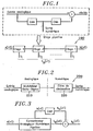
- the operating principle of the pipeline stage involves digitizing the input signal on a small number of bits at means of a flash type converter. Then this numeric code is reconstructed into an analog signal before subtracting it from the input signal (see Figure 1). The resulting signal is called the residue.
- Each floor pipeline treats the residue from the previous stage (except the first floor that receives the input signal) and delivers a new residue to the next stage.
- the delta-sigma analog-to-digital converter consists of a delta-sigma modulator followed by a decimator.
- the delta-sigma modulator oversamples the input signal and rejects the quantization noise outside the useful band.
- the decimator filters in the digital domain the quantization noise formatted and brings back the output rate of the output signal at the frequency of Nyquist.
- delta-sigma modulation makes it possible to reach high performance.
- the conversion band is usually limited to a few kilohertz.
- WO 00/08765 discloses a delta-sigma modulator suitable for analog / digital converters with large bandwidth and high resolution.
- the object of the present invention is to propose a converter analog / digital which has a significant resolution on a band of chosen frequency while leaving an acceptable performance outside of this chosen band.
- a converter analog / digital including a first module of the type having a series stages of treatment, these treatment stages each carrying two first analog / digital and then digital / analog conversions from the output signal from the previous stage and then a signal subtraction as well obtained at the output signal of the previous stage to thereby provide the signal analog output of said stage, said first module further comprising means for assembling the digitized signals by each stage so to form a digital signal that represents in numerical form the input signal of the converter, characterized in that the converter further includes a modulator that digitizes the output signal of a said stages as well as means for subtracting the signal as well digitized to said assembled digital signal.
- the invention also proposes for this purpose a method for producing an analog / digital conversion of an input signal into a signal of output in which a series of processing steps is performed in which we realize, in each, two conversions first analog / digital then digital / analog of a signal-result of the previous step and then a subtraction of the analog signal thus obtained to the result signal of the previous step to thus provide the result signal of the considered step, in which process the signals are assembled.
- digitized at each step to form a digital signal that represents in digital form the input signal, characterized in that that the result signal of one of said steps is further digitized by means of of a delta-sigma modulator and subtract this digitized signal from said signal assembled digital.
- the proposed system uses a delta-sigma modulator 210.
- This modulator 210 increases the performance of the pipeline 100 to a portion of its conversion band.
- the characteristics of the delta-sigma 210 modulator used are condition both the performance gain, the width of the band of increased performance conversion, and the total complexity of the system offers.
- the signal b N (nT) delivered by the delta-sigma modulator 210 consists of the digitized signal b (nT) multiplied by a transfer function of the signal STF (nT) and a new quantization noise q (nT) multiplied by an NTF formatting function (nT) specific to the delta-sigma modulator 210 used.
- a ⁇ modulator includes two functions of transfer, one which is seen by the input signal of the modulator, the other which is seen by the quantization noise (noise shaping function NTF (nT)).
- a module 150 applies a transfer function that is the same as the function seen by the input signal of modulator ⁇ 210.
- the module 150 Before subtracting the signal b N (nT) to s N (nT), the module 150 thus multiplies the latter by the transfer function STF (nT) specific to the delta-sigma modulator.
- the new digital signal obtained with the proposed system consists of the image of the input signal on which is superimposed a noise of power quantization which is lower in a frequency band data.
- the performances of the CAN are then increased, but on a reduced conversion band by the use of delta-sigma modulation (formatting the quantization noise).
- a digital decimation filter 220 is then necessary to suppress the quantization noise rejected in outside the conversion band.
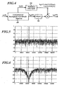
- the proposed system was modeled and simulated on a processing tool of the signal. To validate the original idea, an analog-digital converter 8-bit pipeline 100 and a delta-sigma 210 bandpass modulator 1 bit of order 4 were chosen. The working frequency is 40 MHz. The proposed system is tested by applying a sinusoidal signal of 6.7 MHz frequency.
- Figure 5 shows the output signal of the 8-bit CAN pipeline 100 (conventional operation) on a 20 MHz conversion band.
- the performance of the CAN 100 in terms of signal-to-noise ratio (SNR) are 50 dB (8 bits) on a 20 MHz band and 70 dB (almost 12 bits) effective) on a 200 kHz band around the signal (6.58 - 6.78 MHz).
- Figure 6 shows the output signal of the proposed system (optimized operation) on a 20 MHz band.
- the signal-to-noise ratio is 109 dB (about 18 effective bits).
- the proposed system therefore makes it possible to increase the performance of a pipeline analog-to-digital converter on a frequency band given through the use of a delta-sigma modulator (and a function digital signal processing). This last digitizes the residue of the last Pipeline stage with high accuracy to reduce the noise power quantization in a given frequency band.
- a wide conversion band is required, shown in the figures are provided to disable the delta-sigma modulator 210 (such means are for example a simple switch), the CAN then operating classically in its pipeline mode.
- the proposed system allows more generally to optimize the performance of the CAN around a useful band chosen, by connecting on the CAN pipeline a delta-sigma modulator adapted, for example by connecting using connection means conventional, a low-pass delta-sigma modulator or bandpass according to the need.
- Such a possibility of choice of the delta sigma modulator exists not only at the stage of manufacture of the device but also in use in the case of such a device provided with several modulators and switching means to choose which of these modulators that is associated with CAN pipeline.
- Such a system is particularly suitable for multi-mode communication where the components used in the chain of reception must be reconfigured according to the chosen application in order to share material resources.
- Such terminals are in particular used in telecommunications by radio waves, particularly in the field of the telephone.
Description
L'invention concerne les convertisseurs analogique-numérique.The invention relates to analog-to-digital converters.
Les convertisseurs analogique-numérique se classent en deux grandes familles : les CAN large bande (quelques MHz) avec une résolution moyenne (jusqu'à 10 bits effectifs), et les CAN bande étroite (quelques kHz) et une résolution élevée (jusqu'à 16 bits et plus).The analog-to-digital converters are divided into two large families: broadband ADCs (some MHz) with a resolution average (up to 10 effective bits), and NAC narrowband (a few kHz) and high resolution (up to 16 bits and more).
La conversion analogique-numérique pipeline et la modulation ΔΣ font parties des nombreuses techniques connues dans le domaine de la conversion analogique-numérique. Les CAN pipeline ont généralement une large bande passante (quelques MHz) et une résolution moyenne : de l'ordre de 8 à 10 bits effectifs. Au contraire, les modulateurs ΔΣ sont utilisés pour convertir des signaux avec une résolution élevée (jusqu'à 16 bits et plus), mais sur une bande de fréquences généralement étroite (quelques kHz).Pipeline analog-to-digital conversion and ΔΣ modulation are part of the many techniques known in the field of analog-to-digital conversion. CAN pipeline generally has a bandwidth (a few MHz) and an average resolution: the order of 8 to 10 effective bits. In contrast, ΔΣ modulators are used to convert signals with high resolution (up to 16 bits and more), but on a generally narrow frequency band (some kHz).
Le convertisseur pipeline se compose d'étages de conversion analogique-numérique élémentaires qui sont disposés en pipeline. Chaque étage du pipeline fournit un nombre de bits qui contribue au codage numérique du signal. Le principe de fonctionnement de l'étage pipeline consiste à numériser le signal d'entrée sur un faible nombre de bits au moyen d'un convertisseur de type flash. Ensuite, ce code numérique est reconstruit en un signal analogique avant de le soustraire au signal d'entrée (voir Figure 1). Le signal résultant est appelé le résidu. Chaque étage pipeline traite le résidu de l'étage précédent (sauf le premier étage qui reçoit le signal d'entrée) et délivre un nouveau résidu à l'étage suivant.The pipeline converter consists of conversion stages analog-digital elementary which are arranged in pipeline. Each pipeline stage provides a number of bits that contributes to coding digital signal. The operating principle of the pipeline stage involves digitizing the input signal on a small number of bits at means of a flash type converter. Then this numeric code is reconstructed into an analog signal before subtracting it from the input signal (see Figure 1). The resulting signal is called the residue. Each floor pipeline treats the residue from the previous stage (except the first floor that receives the input signal) and delivers a new residue to the next stage.
De par la précision des composants, le nombre d'étages et la résolution d'un convertisseur analogique-numérique pipeline sont limités. Par contre, cette technique présente l'avantage d'avoir une bande de conversion pouvant atteindre plusieurs MHz.Due to the precision of the components, the number of floors and the resolution of a pipeline analog-to-digital converter are limited. However, this technique has the advantage of having a band of conversion up to several MHz.
Le convertisseur analogique-numérique delta-sigma se compose d'un modulateur delta-sigma suivi d'un décimateur. Le modulateur delta-sigma suréchantillone le signal d'entrée et rejette le bruit de quantification en dehors de la bande utile. Le décimateur filtre dans le domaine numérique le bruit de quantification mis en forme et ramène le débit du signal de sortie à la fréquence de Nyquist.The delta-sigma analog-to-digital converter consists of a delta-sigma modulator followed by a decimator. The delta-sigma modulator oversamples the input signal and rejects the quantization noise outside the useful band. The decimator filters in the digital domain the quantization noise formatted and brings back the output rate of the output signal at the frequency of Nyquist.
Grâce au suréchantillonage et la mise en forme du bruit de quantification, la modulation delta-sigma permet d'atteindre des performances élevées. Toutefois, la bande de conversion est généralement limitée à quelques kilohertz.Thanks to oversampling and noise shaping quantization, delta-sigma modulation makes it possible to reach high performance. However, the conversion band is usually limited to a few kilohertz.
Le document WO 00/08765 divulgue un modulateur delta-sigma approprié pour les convertisseurs analogiques/numériques à grande largeur de bande et à haute résolution.WO 00/08765 discloses a delta-sigma modulator suitable for analog / digital converters with large bandwidth and high resolution.
Le but de la présente invention est de proposer un convertisseur analogique/numérique qui ait une résolution importante sur une bande de fréquence choisie tout en laissant une performance acceptable en dehors de cette bande choisie.The object of the present invention is to propose a converter analog / digital which has a significant resolution on a band of chosen frequency while leaving an acceptable performance outside of this chosen band.
Ce but est atteint selon l'invention grâce à un convertisseur analogique/numérique incluant un premier module du type ayant une série d'étages de traitement, ces étages de traitement réalisant chacun deux conversions d'abord analogique/numérique puis numérique/analogique du signal de sortie de l'étage précédent, puis une soustraction du signal ainsi obtenu au signal de sortie de l'étage précédent pour fournir ainsi le signal de sortie analogique dudit étage, ledit premier module comportant en outre des moyens pour assembler les signaux numérisés par chaque étage afin de former un signal numérique qui représente sous une forme numérique le signal d'entrée du convertisseur, caractérisé en ce que le convertisseur inclut en outre un modulateur qui numérise le signal de sortie d'un desdits étages ainsi que des moyens pour soustraire le signal ainsi numérisé audit signal numérique assemblé.This object is achieved according to the invention by means of a converter analog / digital including a first module of the type having a series stages of treatment, these treatment stages each carrying two first analog / digital and then digital / analog conversions from the output signal from the previous stage and then a signal subtraction as well obtained at the output signal of the previous stage to thereby provide the signal analog output of said stage, said first module further comprising means for assembling the digitized signals by each stage so to form a digital signal that represents in numerical form the input signal of the converter, characterized in that the converter further includes a modulator that digitizes the output signal of a said stages as well as means for subtracting the signal as well digitized to said assembled digital signal.
L'invention propose également pour cela un procédé pour réaliser une conversion analogique/numérique d'un signal d'entrée en un signal de sortie dans lequel on réalise, une série d'étapes de traitement dans lesquelles on réalise, dans chacune, deux conversions d'abord analogique/numérique puis numérique/analogique d'un signal-résultat de l'étape précédente puis une soustraction du signal analogique ainsi obtenu au signal-résultat de l'étape précédente pour fournir ainsi le signal-résultat de l'étape considérée, dans lequel procédé on assemble les signaux numérisés à chaque étape afin de former un signal numérique qui représente sous une forme numérique le signal d'entrée, caractérisé en ce que l'on numérise en outre le signal-résultat d'une desdites étapes à l'aide d'un modulateur delta-sigma et on soustrait ce signal numérisé audit signal numérique assemblé.The invention also proposes for this purpose a method for producing an analog / digital conversion of an input signal into a signal of output in which a series of processing steps is performed in which we realize, in each, two conversions first analog / digital then digital / analog of a signal-result of the previous step and then a subtraction of the analog signal thus obtained to the result signal of the previous step to thus provide the result signal of the considered step, in which process the signals are assembled. digitized at each step to form a digital signal that represents in digital form the input signal, characterized in that that the result signal of one of said steps is further digitized by means of of a delta-sigma modulator and subtract this digitized signal from said signal assembled digital.
D'autres buts, avantages et caractéristiques de l'invention apparaítront à la lecture détaillée de la description qui va suivre, faite en référence aux dessins annexés sur lesquels :
- la figure 1 représente un convertisseur analogique/numérique de type pipeline selon l'art antérieur ;
- la figure 2 représente un convertisseur delta sigma selon l'art antérieur ;
- la figure 3 représente un convertisseur analogique/numérique dans lequel un convertisseur pipeline est associé à un convertisseur analogique/numérique supplémentaire placé à sa sortie ;
- la figure 4 représente un convertisseur analogique/numérique selon l'invention ;
- la figure 5 est un tracé représentant le signal de sortie d'un convertisseur analogique/numérique pipeline selon l'art antérieur ;
- la figure 6 représente est un tracé représentant le signal de sortie d'un convertisseur analogique/numérique pipeline selon l'invention.
- FIG. 1 represents a pipeline analog / digital converter according to the prior art;
- FIG. 2 represents a sigma delta converter according to the prior art;
- FIG. 3 represents an analog / digital converter in which a pipeline converter is associated with an additional analog / digital converter placed at its output;
- FIG. 4 represents an analog / digital converter according to the invention;
- Figure 5 is a plot showing the output signal of a pipeline analog / digital converter according to the prior art;
- FIG. 6 represents a plot representing the output signal of a pipeline analog / digital converter according to the invention.
Le résidu fourni par le dernier étage d'un convertisseur analogique-numérique
pipeline 100 correspond au bruit de quantification du
convertisseur pipeline, tel que :
Dans le présent dispositif décrit représenté aux figures 3 et 4, on numérise le signal d'erreur b(nT) afin de pouvoir le soustraire au signal de sortie numérique s N (nT) de sorte que s N (nT) = e(nT)+b(nT)-b N (nT) où b N (nT) est la représentation de b(nT) dans le domaine numérique. Plus cette représentation sera fidèle, meilleures seront les performances du convertisseur analogique-numérique selon le système proposé. L'idéal étant d'avoir b N (nT) = b(nT). In the present device described in FIGS. 3 and 4, the error signal b (nT) is digitized in order to be able to subtract it from the digital output signal s N (nT) so that s N (nT) = e (nT) ) + b (nT) -b N (nT) where b N (nT) is the representation of b (nT) in the digital domain. The more faithful this representation, the better the performance of the analog-digital converter according to the proposed system. The ideal is to have b N (nT) = b (nT) .
Afin d'avoir une grande précision sur b N (nT), le système proposé
utilise un modulateur delta-sigma 210. Ce modulateur 210 augmente les
performances du convertisseur analogique-numérique pipeline 100 sur une
partie de sa bande de conversion.In order to have a high accuracy on b N (nT) , the proposed system uses a delta-
Les caractéristiques du modulateur delta-sigma 210 utilisé vont
conditionner à la fois le gain en performances, la largeur de la bande de
conversion à performance accrue, et la complexité totale du système
proposé.The characteristics of the delta-
Le signal b N (nT) délivré par le modulateur delta-sigma 210 se
compose du signal numérisé b(nT) multiplié par une fonction de transfert du
signal STF(nT) et d'un nouveau bruit de quantification q(nT) multiplié par une
fonction de mise en forme NTF(nT) propre au modulateur delta-sigma 210
utilisé.The signal b N (nT) delivered by the delta-
De manière connue, un modulateur ΔΣ inclut deux fonctions de transfert, une qui est vue par le signal d'entrée du modulateur, l'autre qui est vue par le bruit de quantification (fonction de mise en forme du bruit NTF(nT)).In known manner, a ΔΣ modulator includes two functions of transfer, one which is seen by the input signal of the modulator, the other which is seen by the quantization noise (noise shaping function NTF (nT)).
Un module 150 applique une fonction de transfert qui est la même que
la fonction vue par le signal d'entrée du modulateur ΔΣ 210.A
Avant de soustraire le signal b N (nT) à s N (nT), on multiplie donc à l'aide
du module 150 ce dernier par la fonction de transfert STF(nT) propre au
modulateur delta-sigma. Ainsi, on obtient le signal y N (nT) tel que :
Il faut en effet que l'autre des deux signaux qui sont soustraits ait également été traité par cette fonction de transfert pour obtenir une efficacité optimale.It is necessary that the other of the two signals which are subtracted also been processed by this transfer function to achieve efficiency optimal.
Généralement, la fonction de transfert de signal est composée
uniquement d'un ou plusieurs retards et on considère STF(nT) = 1 (au retard
près) afin de simplifier le calcul :
Ainsi, le nouveau signal numérique obtenu avec le système proposé se compose de l'image du signal d'entrée sur lequel se superpose un bruit de quantification de puissance qui est plus faible dans une bande de fréquences données.Thus, the new digital signal obtained with the proposed system consists of the image of the input signal on which is superimposed a noise of power quantization which is lower in a frequency band data.
Les performances du CAN sont alors augmentées, mais sur une
bande de conversion réduite par l'utilisation de la modulation delta-sigma
(mise en forme du bruit de quantification). Un filtre numérique de décimation
220 est alors nécessaire pour supprimer le bruit de quantification rejeté en
dehors de la bande de conversion.The performances of the CAN are then increased, but on a
reduced conversion band by the use of delta-sigma modulation
(formatting the quantization noise). A
Le système proposé a été modélisé et simulé sur un outil de traitement
du signal. Pour valider l'idée originale, un convertisseur analogique-numérique
pipeline 100 de 8 bits et un modulateur delta-sigma 210 passe-bande
1 bit d'ordre 4 ont été choisis. La fréquence de travail est de 40 MHz.
Le système proposé est testé en appliquant un signal sinusoïdal de
fréquence 6.7 MHz.The proposed system was modeled and simulated on a processing tool
of the signal. To validate the original idea, an analog-digital converter
8-
La Figure 5 montre le signal de sortie du CAN pipeline 100 à 8 bits
(fonctionnement classique) sur une bande de conversion de 20 MHz. Les
performances du CAN 100 en terme de rapport signal à bruit (SNR) sont de
50 dB (8 bits) sur une bande de 20 MHz et de 70 dB (presque 12 bits
effectifs) sur une bande de 200 kHz autour du signal (6,58 - 6,78 MHz).Figure 5 shows the output signal of the 8-bit CAN pipeline 100
(conventional operation) on a 20 MHz conversion band. The
performance of the
La Figure 6 montre le signal de sortie du système proposé (fonctionnement optimisé) sur une bande de 20 MHz. Sur une bande de 200 kHz autour du signal (6,58 - 6,78 MHz), le rapport signal à bruit est de 109 dB (environ 18 bits effectifs).Figure 6 shows the output signal of the proposed system (optimized operation) on a 20 MHz band. On a strip of 200 kHz around the signal (6.58 - 6.78 MHz), the signal-to-noise ratio is 109 dB (about 18 effective bits).
Le système proposé permet donc d'augmenter les performances d'un convertisseur analogique-numérique pipeline sur une bande de fréquences donnée grâce à l'utilisation d'un modulateur delta-sigma (et d'une fonction numérique de traitement du signal). Ce dernier numérise le résidu du dernier étage pipeline avec une grande précision afin de réduire la puissance du bruit de quantification dans une bande de fréquence donnée.The proposed system therefore makes it possible to increase the performance of a pipeline analog-to-digital converter on a frequency band given through the use of a delta-sigma modulator (and a function digital signal processing). This last digitizes the residue of the last Pipeline stage with high accuracy to reduce the noise power quantization in a given frequency band.
On a donc décrit ici également un procédé de conversion analogique-numérique (CAN) de type pipeline sur lequel le bruit de quantification résiduel est traité par un modulateur ΔΣ afin d'optimiser ses performances sur une bande de fréquences données. We have described here also a conversion process analogue-digital (CAN) pipeline type on which the noise of Residual quantization is processed by a ΔΣ modulator in order to optimize its performance on a given frequency band.
Grâce au dispositif décrit ici, on a en outre la possibilité d'adapter les performances du convertisseur analogique-numérique sur une bande de conversion utile que l'on choisit.Thanks to the device described here, it is also possible to adapt the performance of the analog-to-digital converter on a band of useful conversion that one chooses.
Si une large bande de conversion est nécessaire, des moyens non représentés sur les figures sont prévus pour désactiver le modulateur delta-sigma 210 (de tels moyens sont par exemple un simple interrupteur), le CAN fonctionnant alors classiquement dans son mode pipeline.If a wide conversion band is required, shown in the figures are provided to disable the delta-sigma modulator 210 (such means are for example a simple switch), the CAN then operating classically in its pipeline mode.
Si des performances plus élevées sont nécessaires sur une largeur de
bande réduite, on active le modulateur delta-sigma 210. Le système proposé
permet plus généralement d'optimiser les performances du CAN autour d'une
bande utile choisie, en connectant sur le CAN pipeline un modulateur delta-sigma
adapté, par exemple en connectant à l'aide de moyens de connexion
classiques, un modulateur delta-sigma passe-bas ou passe-bande selon le
besoin.If higher performance is needed over a width of
reduced band, activate the delta-
Une telle possibilité de choix du modulateur delta sigma existe donc non seulement au stade de fabrication du dispositif mais également en utilisation dans le cas d'un tel dispositif muni de plusieurs modulateurs et de moyens de commutation pour choisir celui de ces modulateurs qui est associé au CAN pipeline.Such a possibility of choice of the delta sigma modulator exists not only at the stage of manufacture of the device but also in use in the case of such a device provided with several modulators and switching means to choose which of these modulators that is associated with CAN pipeline.
Un tel système est particulièrement adapté aux terminaux de communication multi-modes où les composants utilisés dans la chaíne de réception doivent se reconfigurer en fonction de l'application choisie afin de partager les ressources matérielles. De tels terminaux sont en particulier utilisés dans les télécommunications par ondes hertziennes, notamment dans le domaine du téléphone.Such a system is particularly suitable for multi-mode communication where the components used in the chain of reception must be reconfigured according to the chosen application in order to share material resources. Such terminals are in particular used in telecommunications by radio waves, particularly in the field of the telephone.
Claims (9)
- Analogue/digital converter including a first module (100) of the type having a series of processing stages, these processing stages each carrying out two conversions, firstly analogue/digital followed by digital/analogue, of the output signal of the previous stage, followed by a subtraction of the signal thus obtained from the output signal of the previous stage so as to thus provide the analogue output signal of the said stage, the said first module (100) furthermore comprising means for assembling the signals digitized by each stage (S1 ..., Si) so as to form a digital signal (SN(nT)) which represents in a digital form the input signal (e(nT)) of the converter, characterized in that the converter furthermore includes a delta-sigma modulator (210) which digitizes the output signal (b(nT)) of one of the said stages as well as means for subtracting the signal thus digitized from the said assembled digital signal (SN(nT)).
- Converter according to Claim 1, characterized in that the means for subtracting the said signal thus digitized from the said assembled digital signal (SN(nT)) include means (150) implementing on the assembled signal a processing corresponding to the transfer function (STF(nT)) of the ΔΣ modulator (210), which function is applied to the input signal of this ΔΣ modulator.
- Converter according to Claim 1 or Claim 2, characterized in that the delta-sigma modulator (200) is placed at the output of the last stage of the first module (100).
- Converter according to any one of the preceding claims, characterized in that it comprises means for deactivating the delta-sigma modulator (210).
- Converter according to any one of the preceding claims, characterized in that it comprises several delta-sigma modulators (210) each able to digitize the output signal from one of the said stages, and switching means for activating a delta-sigma modulator chosen from among these delta-sigma modulators (210).
- Converter according to any one of the preceding claims, characterized in that it includes a decimation filter (220) placed downstream of the said means for assembling the signals digitized by each stage.
- Communications terminal comprising means for choosing a signals emission or reception frequency band, characterized in that it includes a converter according to any one of the preceding claims.
- Method for carrying out an analogue/digital conversion of an input signal (e(nT)) into an output signal (yN(nT)) in which a series of processing steps is carried out in which, in each step, two conversions, firstly analogue/digital and then digital/analogue, of a result signal from the previous step are carried out followed by a subtraction of the analogue signal thus obtained from the result signal of the previous step so as to thus provide the result signal of the step considered, in which method the signals digitized at each step (S1 ..., Si) are assembled so as to form a digital signal (SN(nT)) which represents in a digital form the input signal (e(nT)), characterized in that the result signal of one of the said steps (b(nT)) is furthermore digitized with the aid of a delta-sigma modulator (210) and this digitized signal (bN(nT)) is subtracted from the said assembled digital signal (SN(nT)).
- Method according to Claim 8, characterized in that a processing corresponding to the transfer function (STF(nT)) of the delta-sigma modulator (210) is implemented (150) on the assembled signal (SN(nT)), which function is applied to the input signal of this ΔΣ modulator (210).
Applications Claiming Priority (2)
| Application Number | Priority Date | Filing Date | Title |
|---|---|---|---|
| FR0006198A FR2809247A1 (en) | 2000-05-16 | 2000-05-16 | PIPELINE ANALOG-TO-DIGITAL CONVERTER WITH NOISE SHAPING |
| FR0006198 | 2000-05-16 |
Publications (2)
| Publication Number | Publication Date |
|---|---|
| EP1156586A1 EP1156586A1 (en) | 2001-11-21 |
| EP1156586B1 true EP1156586B1 (en) | 2005-09-07 |
Family
ID=8850256
Family Applications (1)
| Application Number | Title | Priority Date | Filing Date |
|---|---|---|---|
| EP01401228A Expired - Lifetime EP1156586B1 (en) | 2000-05-16 | 2001-05-14 | Pipelined analogue-to-digital converter with noise-shaping |
Country Status (4)
| Country | Link |
|---|---|
| US (1) | US6507305B2 (en) |
| EP (1) | EP1156586B1 (en) |
| DE (1) | DE60113183D1 (en) |
| FR (1) | FR2809247A1 (en) |
Families Citing this family (5)
| Publication number | Priority date | Publication date | Assignee | Title |
|---|---|---|---|---|
| US7034730B2 (en) * | 2003-10-03 | 2006-04-25 | Wright State University | Pipelined delta sigma modulator analog to digital converter |
| US20050162295A1 (en) * | 2004-01-27 | 2005-07-28 | Victor Dias | Analog-to-digital converter comprising a sigma-delta modulator |
| TWI227071B (en) * | 2004-04-13 | 2005-01-21 | Realtek Semiconductor Corp | Pipeline ADC calibrating method utilizing extra ADC module and apparatus thereof |
| US10536161B1 (en) | 2018-10-08 | 2020-01-14 | Analog Devices, Inc. | Noise shaping pipeline analog to digital converters |
| US11038515B2 (en) | 2019-05-13 | 2021-06-15 | Analog Devices, Inc. | Noise shaping algorithmic analog-to-digital converter |
Family Cites Families (13)
| Publication number | Priority date | Publication date | Assignee | Title |
|---|---|---|---|---|
| US4684924A (en) * | 1982-09-30 | 1987-08-04 | Wood Lawson A | Analog/digital converter using remainder signals |
| JP2543095B2 (en) * | 1987-09-14 | 1996-10-16 | 松下電器産業株式会社 | Oversampling type D / A converter |
| US4894657A (en) * | 1988-11-25 | 1990-01-16 | General Electric Company | Pipelined analog-to-digital architecture with parallel-autozero analog signal processing |
| US5043732A (en) * | 1989-09-26 | 1991-08-27 | Analog Devices, Inc. | Analog-to-digital converter employing a pipeline multi-stage architecture |
| NL9001440A (en) * | 1990-06-22 | 1992-01-16 | Philips Nv | ANALOG / DIGITAL SIGNAL INVERTER WITH MULTIPLE SIGMA DELTA MODULATOR. |
| US5181032A (en) * | 1991-09-09 | 1993-01-19 | General Electric Company | High-order, plural-bit-quantization sigma-delta modulators using single-bit digital-to-analog conversion feedback |
| US5742246A (en) * | 1996-03-22 | 1998-04-21 | National Science Council | Stabilizing mechanism for sigma-delta modulator |
| SE516675C2 (en) * | 1996-05-07 | 2002-02-12 | Ericsson Telefon Ab L M | Method and apparatus for converting an analog current to a digital signal |
| US5771012A (en) * | 1996-09-11 | 1998-06-23 | Harris Corporation | Integrated circuit analog-to-digital converter and associated calibration method and apparatus |
| US5838272A (en) * | 1997-04-17 | 1998-11-17 | President And Fellows Of Harvard College | Error correcting sigma-delta modulation decoding |
| US6166675A (en) * | 1997-09-03 | 2000-12-26 | Texas Instruments Incorporated | Pipeline analog-to-digital conversion system using double sampling and method of operation |
| WO2000008765A2 (en) * | 1998-08-06 | 2000-02-17 | Steensgaard Madsen Jesper | Delta-sigma a/d converter |
| US6285309B1 (en) * | 1999-09-14 | 2001-09-04 | Texas Instruments Incorporated | Nested pipelined analog-to-digital converter |
-
2000
- 2000-05-16 FR FR0006198A patent/FR2809247A1/en active Pending
-
2001
- 2001-05-14 EP EP01401228A patent/EP1156586B1/en not_active Expired - Lifetime
- 2001-05-14 DE DE60113183T patent/DE60113183D1/en not_active Expired - Lifetime
- 2001-05-16 US US09/855,746 patent/US6507305B2/en not_active Expired - Lifetime
Also Published As
| Publication number | Publication date |
|---|---|
| US6507305B2 (en) | 2003-01-14 |
| US20020024459A1 (en) | 2002-02-28 |
| FR2809247A1 (en) | 2001-11-23 |
| DE60113183D1 (en) | 2005-10-13 |
| EP1156586A1 (en) | 2001-11-21 |
Similar Documents
| Publication | Publication Date | Title |
|---|---|---|
| US7576671B2 (en) | Mismatch-shaping dynamic element matching systems and methods for multi-bit sigma-delta data converters | |
| JP3100105B2 (en) | Intermediate frequency digital receiver and baseband filtering method implemented in the receiver | |
| JP4261585B2 (en) | Delta-sigma analog-digital converter | |
| US7304592B2 (en) | Method of adding a dither signal in output to the last integrator of a sigma-delta converter and relative sigma-delta converter | |
| US6922161B2 (en) | Delta-Sigma modulator for reducing quantization noise and oversampling ratio (OSR) | |
| US6326911B1 (en) | Method and apparatus for dithering idle channel tones in delta-sigma analog-to-digital converters | |
| JPH0797749B2 (en) | Delta-sigma modulation circuit of analog digital converter | |
| US20050088327A1 (en) | Delta sigma modulating apparatus | |
| EP2360839A1 (en) | Continuous-time analogue-to-digital converter | |
| FR2765419A1 (en) | DEVICE FOR GENERATING ANALOG SIGNALS FROM ANALOG-TO-DIGITAL CONVERTERS, PARTICULARLY FOR DIRECT DIGITAL SYNTHESIS | |
| US6940438B2 (en) | Method and circuit for reducing quantizer input/output swing in a sigma-delta modulator | |
| EP1156586B1 (en) | Pipelined analogue-to-digital converter with noise-shaping | |
| CA2450702A1 (en) | Bandpass sigma-delta analog-to-digital converter and mash sigma-delta converter incorporating same | |
| EP3276833A1 (en) | Sigma-delta converter with high linearity | |
| FR3105897A1 (en) | Analog-to-digital conversion device comprising two cascaded analog-to-digital conversion stages with successive approximation register and noise shaping, and associated electronic sensor | |
| WO2001001578A1 (en) | Method for compensating non-linearity of a sigma-delta analog-to-digital converter | |
| EP1678832B1 (en) | Delta sigma modulator with integral decimation | |
| EP1077530B1 (en) | Method and arrangement for the conversion of an analogue signal into a digital signal with automatic gain control | |
| WO2008102091A2 (en) | Method for processing a digital signal in a digital delta-sigma modulator, and digital delta-sigma modulator therefor | |
| FI103745B (en) | Signal processing method and device | |
| FR2730590A1 (en) | METHOD AND APPARATUS FOR REDUCING AND QUANTIFYING NOISE | |
| EP4333313A1 (en) | Multi-channel transmission and/or reception system comprising at least n parallel processing channels and method for de-correlation of quantization noise in such a system | |
| EP2342828A1 (en) | Method for improving the resolution and the correction of distortions in a sigma-delta modulator, and sigma-delta modulator implementing said method | |
| FR3060913A1 (en) | DIGITAL ENCODER FOR MODULATED SIGNALS, AND DEVICE FOR GENERATING AN ANALOGUE SIGNAL | |
| FR3139255A1 (en) | Transmitter device, noise predistortion and decorrelation methods in such a transmitter device |
Legal Events
| Date | Code | Title | Description |
|---|---|---|---|
| PUAI | Public reference made under article 153(3) epc to a published international application that has entered the european phase |
Free format text: ORIGINAL CODE: 0009012 |
|
| AK | Designated contracting states |
Kind code of ref document: A1 Designated state(s): AT BE CH CY DE DK ES FI FR GB GR IE IT LI LU MC NL PT SE TR Kind code of ref document: A1 Designated state(s): DE FR GB |
|
| AX | Request for extension of the european patent |
Free format text: AL;LT;LV;MK;RO;SI |
|
| 17P | Request for examination filed |
Effective date: 20020408 |
|
| AKX | Designation fees paid |
Free format text: DE FR GB |
|
| 17Q | First examination report despatched |
Effective date: 20040423 |
|
| GRAP | Despatch of communication of intention to grant a patent |
Free format text: ORIGINAL CODE: EPIDOSNIGR1 |
|
| RIN1 | Information on inventor provided before grant (corrected) |
Inventor name: PAILLARDET, FREDERIC Inventor name: ANDRE, ERIC |
|
| GRAS | Grant fee paid |
Free format text: ORIGINAL CODE: EPIDOSNIGR3 |
|
| GRAA | (expected) grant |
Free format text: ORIGINAL CODE: 0009210 |
|
| AK | Designated contracting states |
Kind code of ref document: B1 Designated state(s): DE FR GB |
|
| REG | Reference to a national code |
Ref country code: GB Ref legal event code: FG4D Free format text: NOT ENGLISH |
|
| REF | Corresponds to: |
Ref document number: 60113183 Country of ref document: DE Date of ref document: 20051013 Kind code of ref document: P |
|
| PG25 | Lapsed in a contracting state [announced via postgrant information from national office to epo] |
Ref country code: DE Free format text: LAPSE BECAUSE OF FAILURE TO SUBMIT A TRANSLATION OF THE DESCRIPTION OR TO PAY THE FEE WITHIN THE PRESCRIBED TIME-LIMIT Effective date: 20051208 |
|
| GBT | Gb: translation of ep patent filed (gb section 77(6)(a)/1977) |
Effective date: 20060109 |
|
| PLBE | No opposition filed within time limit |
Free format text: ORIGINAL CODE: 0009261 |
|
| STAA | Information on the status of an ep patent application or granted ep patent |
Free format text: STATUS: NO OPPOSITION FILED WITHIN TIME LIMIT |
|
| 26N | No opposition filed |
Effective date: 20060608 |
|
| PGFP | Annual fee paid to national office [announced via postgrant information from national office to epo] |
Ref country code: GB Payment date: 20070427 Year of fee payment: 7 |
|
| PGFP | Annual fee paid to national office [announced via postgrant information from national office to epo] |
Ref country code: FR Payment date: 20070529 Year of fee payment: 7 |
|
| GBPC | Gb: european patent ceased through non-payment of renewal fee |
Effective date: 20080514 |
|
| REG | Reference to a national code |
Ref country code: FR Ref legal event code: ST Effective date: 20090119 |
|
| PG25 | Lapsed in a contracting state [announced via postgrant information from national office to epo] |
Ref country code: FR Free format text: LAPSE BECAUSE OF NON-PAYMENT OF DUE FEES Effective date: 20080602 |
|
| PG25 | Lapsed in a contracting state [announced via postgrant information from national office to epo] |
Ref country code: GB Free format text: LAPSE BECAUSE OF NON-PAYMENT OF DUE FEES Effective date: 20080514 |