EP1156579B1 - Spuleanordnung für linearmotoren und verfahren zur herstellung - Google Patents
Spuleanordnung für linearmotoren und verfahren zur herstellung Download PDFInfo
- Publication number
- EP1156579B1 EP1156579B1 EP00970243A EP00970243A EP1156579B1 EP 1156579 B1 EP1156579 B1 EP 1156579B1 EP 00970243 A EP00970243 A EP 00970243A EP 00970243 A EP00970243 A EP 00970243A EP 1156579 B1 EP1156579 B1 EP 1156579B1
- Authority
- EP
- European Patent Office
- Prior art keywords
- coils
- cooling tube
- linear motor
- cores
- coil assembly
- Prior art date
- Legal status (The legal status is an assumption and is not a legal conclusion. Google has not performed a legal analysis and makes no representation as to the accuracy of the status listed.)
- Expired - Lifetime
Links
Images




Classifications
-
- H—ELECTRICITY
- H02—GENERATION; CONVERSION OR DISTRIBUTION OF ELECTRIC POWER
- H02K—DYNAMO-ELECTRIC MACHINES
- H02K41/00—Propulsion systems in which a rigid body is moved along a path due to dynamo-electric interaction between the body and a magnetic field travelling along the path
- H02K41/02—Linear motors; Sectional motors
- H02K41/03—Synchronous motors; Motors moving step by step; Reluctance motors
- H02K41/031—Synchronous motors; Motors moving step by step; Reluctance motors of the permanent magnet type
-
- H—ELECTRICITY
- H02—GENERATION; CONVERSION OR DISTRIBUTION OF ELECTRIC POWER
- H02K—DYNAMO-ELECTRIC MACHINES
- H02K3/00—Details of windings
- H02K3/04—Windings characterised by the conductor shape, form or construction, e.g. with bar conductors
- H02K3/24—Windings characterised by the conductor shape, form or construction, e.g. with bar conductors with channels or ducts for cooling medium between the conductors
-
- H—ELECTRICITY
- H02—GENERATION; CONVERSION OR DISTRIBUTION OF ELECTRIC POWER
- H02K—DYNAMO-ELECTRIC MACHINES
- H02K41/00—Propulsion systems in which a rigid body is moved along a path due to dynamo-electric interaction between the body and a magnetic field travelling along the path
- H02K41/02—Linear motors; Sectional motors
-
- Y—GENERAL TAGGING OF NEW TECHNOLOGICAL DEVELOPMENTS; GENERAL TAGGING OF CROSS-SECTIONAL TECHNOLOGIES SPANNING OVER SEVERAL SECTIONS OF THE IPC; TECHNICAL SUBJECTS COVERED BY FORMER USPC CROSS-REFERENCE ART COLLECTIONS [XRACs] AND DIGESTS
- Y10—TECHNICAL SUBJECTS COVERED BY FORMER USPC
- Y10T—TECHNICAL SUBJECTS COVERED BY FORMER US CLASSIFICATION
- Y10T29/00—Metal working
- Y10T29/49—Method of mechanical manufacture
- Y10T29/49002—Electrical device making
- Y10T29/49009—Dynamoelectric machine
-
- Y—GENERAL TAGGING OF NEW TECHNOLOGICAL DEVELOPMENTS; GENERAL TAGGING OF CROSS-SECTIONAL TECHNOLOGIES SPANNING OVER SEVERAL SECTIONS OF THE IPC; TECHNICAL SUBJECTS COVERED BY FORMER USPC CROSS-REFERENCE ART COLLECTIONS [XRACs] AND DIGESTS
- Y10—TECHNICAL SUBJECTS COVERED BY FORMER USPC
- Y10T—TECHNICAL SUBJECTS COVERED BY FORMER US CLASSIFICATION
- Y10T29/00—Metal working
- Y10T29/49—Method of mechanical manufacture
- Y10T29/49002—Electrical device making
- Y10T29/4902—Electromagnet, transformer or inductor
- Y10T29/49071—Electromagnet, transformer or inductor by winding or coiling
-
- Y—GENERAL TAGGING OF NEW TECHNOLOGICAL DEVELOPMENTS; GENERAL TAGGING OF CROSS-SECTIONAL TECHNOLOGIES SPANNING OVER SEVERAL SECTIONS OF THE IPC; TECHNICAL SUBJECTS COVERED BY FORMER USPC CROSS-REFERENCE ART COLLECTIONS [XRACs] AND DIGESTS
- Y10—TECHNICAL SUBJECTS COVERED BY FORMER USPC
- Y10T—TECHNICAL SUBJECTS COVERED BY FORMER US CLASSIFICATION
- Y10T29/00—Metal working
- Y10T29/49—Method of mechanical manufacture
- Y10T29/49002—Electrical device making
- Y10T29/4902—Electromagnet, transformer or inductor
- Y10T29/49073—Electromagnet, transformer or inductor by assembling coil and core
Definitions
- the present invention relates to a linear motor for generating linear movement. More particularly, the present invention relates to a linear motor coil assembly having a plurality of coils arranged in a line in the direction of linear motion.
- Linear motors are known that use a linear motor to cause a table to move linearly at high speed and to position the table with high precision.
- linear motors have become more widely used. Such motors do not a require conveying means such as a feed screw.
- a linear motor may be used in a machine tool when it is needed to generate a large thrust, and where more compact structures are needed.
- linear motors generate more heat than rotary motors.
- the temperature rise associated with a linear motor may limit its rated thrust, and lower its mechanical positioning accuracy.
- linear motors are encapsulated in a cover in order to prevent magnetic dust from infiltrating into the linear motor. Because of this encapsulation, insufficient natural cooling of the linear motor may result, making effective cooling of the linear motor an important consideration.
- Japanese Laid-Open Patent Application 63-18956 discloses a cooling apparatus for a linear motor.
- the motor is equipped with a cooling tube at the bottom of a groove formed between adjoining pole teeth.
- This linear motor cooling tube will now be described in detail below with reference to Fig. 9, Fig. 10 and Fig. 11 .
- a plurality of permanent magnets 3 having alternating magnetic poles are fixed in a line on the lower surface of a carrier 2 in the direction of movement.
- a fixed armature is made up of a plurality of T-shaped pole teeth 4, a base 5 connecting the pole teeth, and a coil 7 wound around the teeth 4.
- cooling tubes 8 are provided, one each at the bottom of grooves 6 formed by adjoining pole teeth 4.
- the cooling tubes 8 are, for example, a tube 8A meandering around the grooves 6, as shown in Fig. 10 .
- a coolant in gas or liquid form circulates in the pipe 8A.
- the cooling tubes 8, as shown in Fig. 11 can be stair-shaped pipes 8B.
- the pipes 8B are equipped with headers 8a and 8b extending parallel to a moving direction opposite with respect to the base 5, and a bridging section 8c bridging the headers 8a and 8b.
- the coolant is introduced from one end of the header 8a, passes through the bridging section 8c and is discharged from one end of the header 8b.
- An object of the present invention is to provide a linear motor coil assembly that efficiently cools heat generated in the coil.
- Another object of the present invention is to provide a compact linear motor coil assembly.
- Still another object of the present invention is to provide a method of simply manufacturing a linear motor coil assembly, having high cooling efficiency.
- a linear motor coil assembly for developing linear motion, comprising a plurality of coils arranged in a line in a direction of movement, each coil having an associated coil axis, said coil axes being perpendicular to the direction of motion, and a cooling tube; characterized in that said cooling tube is flat and has a cross section elongated in a direction parallel to the coil axes and folds into which said coils are adapted to engage, said cooling tube meandering around the plurality of coils.
- the flat cooling pipe preferably has a plurality of clearance holes for passing coolant, formed in a direction parallel to the coil axes.
- the flat cooling pipe may be formed by aligning and attaching a plurality of round pipes for passing coolant in a direction parallel to the coil axes.
- the flat cooling tube preferably has interleaved folds at least equal in number to the number of coils.
- the linear motor coil assembly may also include cores, divided for each coil, around which the coils are wound.
- a method of manufacturing a linear motor assembly for developing linear motion characterized by: providing a plurality of divided cores, each one for a magnetic pole; winding coils around the respective cores; providing a flat cooling tube elongated in a direction parallel to the coil cores and having a number of folds being at least equal to the number of coils, into which folds said coils are engageable, said cooling tube meandering around the coils; fitting the cores into the folds; and arranging the cores in a line.
- a linear motor coil assembly according to an embodiment of the present invention will now be described with reference to Fig. 1 , Fig. 2 , Fig. 3 and Fig. 4 .
- a linear motor coil assembly 12 for developing motion in the direction of a horizontal linear axis X has a base plate 11 , cores 13 having coils 14 mounted thereon.
- the coil assembly 12 may constitute either a mover or a stator.
- Reference numeral G1 in Fig. 1 represents a gap formed between a stator and a mover.
- the base plate 11 has a horizontal upper surface.
- the cores 13 divided for each magnetic pole and aligned in a line in the direction of the linear axis X are attached to the upper surface of the base plate 11 using screws 19 .
- a plurality of holes 18 for the screws 19 are formed in the base plate.
- the cores 13 are preferably formed by laminating silicon-steel plates and welding or gluing them together. As illustrated in Fig.
- the cores 13 extend parallel to each other in a horizontal direction Y perpendicular to the linear axis X.
- a gap G2 is formed between pole faces 13a of adjoining cores 13 .
- the pole faces 13a of the cores 13 protrude in the direction of the linear axis X.
- the size of the gap G2 is preferably maintained at a value about double the gap G1 .
- a small gap G2 reduces undesirable torque ripple.
- a yoke section 13b is formed connecting adjoining cores 13 , and holes 13c for screws 19 are formed in the yoke section 13b .
- a set of insulators 15 for insulating the coils 14 , are inserted into the cores 13 .
- the coils 14 are wound around respective cores 13 via insulators 15 , preferably without overlapping.
- the coil axes Z are parallel to each other, and perpendicular to the linear axis X.
- the insulators 15 may, for example, be made of compact liquid crystal polymer resin capable of being thinly formed and having high thermal conductivity.
- the insulators 15 have a generally U-shaped horizontal cross section, and a set of insulators are fit onto each core 13 .
- Tapered insulators 16 for preventing damage to the finish, e.g., enamel paint, of the coils 14 are preferably wrapped around the outside of the coils 14 .
- a flat cooling tube 20 arranged so as to meander around the inside of the coils 14 , is arranged in the direction of the linear axis X.
- the cooling tube 20 is preferably made of extruded aluminum.
- the cooling tube 20 is preferably glued to the coils 14 , and the insulators 16 improve adherence between the coils 14 and the cooling tube 20 .
- the cooling tube 20 has a cross section elongated parallel to the coil axes Z, and is arranged higher than the height H1 of the yoke section 13b .
- the length of the elongated cross section is preferably the same as, or slightly larger than, the length L of the coils 14 in the axial direction.
- the cooling tube 20 is glued to almost the entire outer surface of the coils 14 , which are a source of heat.
- a plurality of holes 25 are formed in the cooling tube 20 in a direction parallel to the coil axes.
- the cooling tube 20 does not have any branches, which means that no stagnation occurs in the flow of coolant.
- heat generated in the coils 14 which is conducted to an outer side is directly cooled by coolant inside the cooling tube 20 . Heat conducted from the coils 14 to the cores 13 is transferred through pole surfaces 13a close to the cooling tube 20 and the yoke section 13b to the cooling tube 20 .
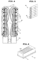
- Fig. 5 illustrates another example of the cooling tube 20 .
- the cooling tube 20 of Fig. 5 has a plurality of round copper pipes arranged parallel to the coil axes Z. Adjoining copper pipes 26 are preferably joined by brazing.
- the two ends 20a and 20b of the cooling tube 20 are connected to respective manifolds 21 and 22 , preferably by welding.
- a row of cores is made up of nine cores 13 .
- the coils 14 are wound around the cores 13 using a coil winding machine. Since the cores are divided for each coil 14 , winding of the coils 14 is simple.
- a flat cooling tube 20 having interleaved folds at least equal in number to the number of coils 14 is provided in the illustrated embodiment a flat cooling tube 20 having nine interleaved folds is provided.
- the folds of the cooling tube 20 are formed to correspond to the outline of the coils 14 , so that the coils 14 fit into the folds.
- the two ends of the cooling tube 20 are fixed preferably by welding, to elongated holes formed in manifolds 21 and 22 .
- the cooling tube 20 is moved horizontally, and the folds of the cooling tube 20 fit into two coils 14 on the base plate 11 .
- three cores 13 are then moved horizontally, and inserted into folds of the cooling tube 20 .
- an odd number, in this case five, cores of the row of cores are arranged on the upper plane of the base plate.
- the coil assembly 12 may be covered with a box-shaped frame.
- the frame is filled with insulating resin until the pole faces 13a of the cores 13 are covered.
- the fixed resin compact may then be finished to the specified dimensions so as to expose the pole faces 13a .
- Fig. 8 depicts the coil assembly covered with the insulating resin as described above. Where the insulating resin sufficiently permeates into the coil assembly 12 , there is no need for the insulators 16 .
Landscapes
- Engineering & Computer Science (AREA)
- Power Engineering (AREA)
- Physics & Mathematics (AREA)
- Chemical & Material Sciences (AREA)
- Combustion & Propulsion (AREA)
- Electromagnetism (AREA)
- Linear Motors (AREA)
- Motor Or Generator Cooling System (AREA)
Claims (8)
- Spulenanordnung für Linearmotor (12) zur Entwicklung von Linearbewegung, die eine Mehrheit von Spulen (14) umfasst, die in einer Linie in der Bewegungsrichtung angeordnet sind, wobei jede Spule eine zugehörige Spulenachse (Z) hat, besagte Spulenachsen senkrecht zur Bewegungsachse (X) sind und ein Kühlrohr (20) aufweist;
dadurch gekennzeichnet, dass besagtes Kühlrohr (20) flach ist und einen Querschnitt aufweist, der in einer Richtung parallel zu den Spulenachsen und Falten verlängert ist, in die besagte Spulen (14) einzugreifen adaptiert sind, wobei besagtes Kühlrohr (20) um die Mehrheit von Spulen (14) mäandert. - Spulenanordnung für Linearmotor nach Anspruch 1, wobei das flache Kühlrohr eine Mehrheit von Durchgangslöchern (25) zum Durchtreten von Kühlmittel aufweist, wobei besagte Durchgangslöcher in einer zu den Spulenachsen parallelen Richtung gebildet sind.
- Spulenanordnung für Linearmotor nach Anspruch 1, wobei das flache Kühlrohr eine Mehrheit runder Rohre (26) zum Durchtreten von Kühlmittel aufweist, wobei besagte Rohre in einer zu den Spulenachsen parallelen Richtung ausgerichtet und befestigt sind.
- Spulenanordnung für Linearmotor nach Anspruch 1, wobei das flache Kühlrohr verzahnte Falten aufweist, die der Zahl nach mindestens der Zahl von Spulen entsprechen.
- Spulenanordnung für Linearmotor nach Anspruch 1, wobei der verlängerte Querschnitt des flachen Kühlrohrs gleich der oder geringfügig größer als die Länge der Spulen in einer axialen Richtung ist.
- Spulenanordnung für Linearmotor nach Anspruch 1, die weiter Kerne (13) - geteilt für jede Spule - umfasst, um welche die Spulen gewickelt sind.
- Spulenanordnung für Linearmotor nach Anspruch 6, die weiter eine Bodenplatte (11) umfasst, wobei die Kerne an der Bodenplatte in einer Linie befestigt sind, die generell parallel zur Bewegungsrichtung verläuft.
- Verfahren zur Herstellung einer Linearmotoranordnung zum Entwickeln von Linearbewegung, gekennzeichnet durch:Bereitstellen einer Mehrheit geteilter Kerne (13), jeder für einen magnetischen Pol;
Wickeln von Spulen (14) um jeweilige Kerne (13);Bereitstellen eines flachen Kühlrohrs (20), das in einer Richtung parallel zu den Spulenkernen (13) verlängert ist und eine Zahl von Falten aufweist, die mindestens gleich der Zahl von Spulen (14) ist, in welche Falten besagte Spulen (14) in Eingriff bringbar sind, wobei besagtes Kühlrohr (20) um die Spulen (14) mäandert;Montieren der Kerne (13) in die Falten; undAnordnen der Kerne (13) in einer Linie.
Applications Claiming Priority (3)
| Application Number | Priority Date | Filing Date | Title |
|---|---|---|---|
| JP30719999A JP3643273B2 (ja) | 1999-10-28 | 1999-10-28 | リニアモータのコイル装置およびその製造方法 |
| JP30719999 | 1999-10-28 | ||
| PCT/JP2000/007669 WO2001031768A1 (en) | 1999-10-28 | 2000-10-30 | Linear motor coil assembly and method for manufacturing the same |
Publications (3)
| Publication Number | Publication Date |
|---|---|
| EP1156579A1 EP1156579A1 (de) | 2001-11-21 |
| EP1156579A4 EP1156579A4 (de) | 2005-08-17 |
| EP1156579B1 true EP1156579B1 (de) | 2008-10-29 |
Family
ID=17966242
Family Applications (1)
| Application Number | Title | Priority Date | Filing Date |
|---|---|---|---|
| EP00970243A Expired - Lifetime EP1156579B1 (de) | 1999-10-28 | 2000-10-30 | Spuleanordnung für linearmotoren und verfahren zur herstellung |
Country Status (8)
| Country | Link |
|---|---|
| US (2) | US6661124B1 (de) |
| EP (1) | EP1156579B1 (de) |
| JP (1) | JP3643273B2 (de) |
| KR (1) | KR100702821B1 (de) |
| CN (1) | CN100488006C (de) |
| DE (1) | DE60040650D1 (de) |
| TW (1) | TW550872B (de) |
| WO (1) | WO2001031768A1 (de) |
Cited By (1)
| Publication number | Priority date | Publication date | Assignee | Title |
|---|---|---|---|---|
| US11496035B2 (en) | 2018-09-19 | 2022-11-08 | Motorola Solutions, Inc. | Homopolar linear synchronous machine |
Families Citing this family (71)
| Publication number | Priority date | Publication date | Assignee | Title |
|---|---|---|---|---|
| JP3643273B2 (ja) | 1999-10-28 | 2005-04-27 | 株式会社ソディック | リニアモータのコイル装置およびその製造方法 |
| JP3907912B2 (ja) * | 2000-03-30 | 2007-04-18 | 株式会社ソディック | リニア直流モータ用1次側部材およびリニア直流モータ |
| DE60230947D1 (de) * | 2001-04-20 | 2009-03-12 | Converteam Ltd | Kühlung von Luftspaltelektrischermaschinewicklungen |
| DE10131119A1 (de) * | 2001-06-28 | 2003-01-23 | Siemens Linear Motor Systems G | Elektromotor mit Kühlschlange |
| KR100432243B1 (ko) | 2001-07-06 | 2004-05-22 | 삼익Lms주식회사 | 방열구조를 가진 리니어모터 |
| KR100441227B1 (ko) * | 2001-12-15 | 2004-07-21 | 미래산업 주식회사 | 리니어 모터의 냉각장치 |
| CN100342627C (zh) * | 2002-09-18 | 2007-10-10 | 思考电机(上海)有限公司 | 用于线圈可动型移动子的制造方法 |
| JP4216046B2 (ja) * | 2002-11-05 | 2009-01-28 | 株式会社ソディック | コアレス交流リニアモータ |
| US6946761B2 (en) * | 2003-04-18 | 2005-09-20 | Asml Holding, N.V. | Actuator coil cooling system |
| CN1319255C (zh) * | 2003-10-15 | 2007-05-30 | 哈尔滨工业大学 | 具有复合运动平台的直线电机 |
| CN100369368C (zh) * | 2003-10-31 | 2008-02-13 | 哈尔滨工业大学 | 具有双动子绕组单元的直线电机 |
| CN100334796C (zh) * | 2003-10-31 | 2007-08-29 | 哈尔滨工业大学 | 具有双动子绕组单元和复合运动平台的直线电机 |
| JP4492118B2 (ja) * | 2003-12-16 | 2010-06-30 | 株式会社安川電機 | リニアモータおよび吸引力相殺形リニアモータ |
| JP2005184984A (ja) * | 2003-12-19 | 2005-07-07 | Yaskawa Electric Corp | ムービングマグネット形リニアアクチュエータ |
| JP4574224B2 (ja) * | 2004-05-12 | 2010-11-04 | 山洋電気株式会社 | リニアモータ |
| US8030818B2 (en) * | 2004-06-15 | 2011-10-04 | Siemens Energy, Inc. | Stator coil with improved heat dissipation |
| JP2006032490A (ja) * | 2004-07-13 | 2006-02-02 | Hitachi Ltd | エンジン制御回路装置 |
| US7732950B2 (en) * | 2004-07-25 | 2010-06-08 | Ts Heatronics Co., Ltd. | Linear or curved mobile motor and its radiator |
| EP1655824B1 (de) * | 2004-11-08 | 2008-04-09 | Etel S.A. | Linearmotor mit Segmentstator |
| US7242117B2 (en) * | 2004-11-25 | 2007-07-10 | Sanyo Denki Co., Ltd. | Linear motor |
| CN101009453B (zh) * | 2006-01-26 | 2011-04-06 | 深圳市大族电机科技有限公司 | 动圈式直线电机 |
| DE102006012736A1 (de) * | 2006-03-17 | 2007-09-20 | Siemens Ag | Elektrische Maschine |
| FR2900287B1 (fr) * | 2006-04-20 | 2008-11-07 | Sidel Participations | Support pour un moteur electrique lineaire comportant des moyens de compensation thermique |
| JP2007143398A (ja) * | 2007-02-26 | 2007-06-07 | Nsk Ltd | リニアモータ |
| JP5292707B2 (ja) * | 2007-03-06 | 2013-09-18 | 株式会社ジェイテクト | 可動磁石型リニアモータ |
| DE102007038848A1 (de) * | 2007-08-16 | 2009-02-19 | Dorma Gmbh + Co. Kg | Spulenkörper für einen Linearmotor-Stator für eine automatische Tür |
| CN101939897B (zh) * | 2008-02-14 | 2014-03-12 | Thk株式会社 | 线性电动机 |
| NL1035273C2 (nl) * | 2008-04-09 | 2009-10-12 | P3W Invest B V | Stator-element en schuifdeur voorzien daarvan, en een werkwijze voor het verschuiven van een element zoals een deur. |
| US7934307B2 (en) * | 2008-08-22 | 2011-05-03 | Baldor Electric Company | Method of constructing a linear drive motor assembly with a core |
| US8664808B2 (en) | 2008-10-23 | 2014-03-04 | Sodick Co., Ltd. | Linear motor coil assembly with cooling device |
| EP2182570A1 (de) | 2008-10-28 | 2010-05-05 | Siemens Aktiengesellschaft | Anordnung zur Kühlung einer elektrischen Maschine |
| JP5426180B2 (ja) * | 2009-01-20 | 2014-02-26 | 富士機械製造株式会社 | リニアモータ |
| JP5355105B2 (ja) * | 2009-01-20 | 2013-11-27 | 富士機械製造株式会社 | 直線駆動装置および電子回路部品装着機 |
| JP5399470B2 (ja) * | 2009-03-05 | 2014-01-29 | 山洋電気株式会社 | リニアモータ用電機子 |
| US20120062866A1 (en) * | 2010-09-03 | 2012-03-15 | Nikon Corporation | Microchannel-cooled coils of electromagnetic actuators exhibiting reduced eddy-current drag |
| EP2498380A1 (de) * | 2011-03-09 | 2012-09-12 | Siemens Aktiengesellschaft | Statoranordnung |
| US9729020B2 (en) * | 2011-03-22 | 2017-08-08 | Hamilton Sundstrand Corporation | Motor stator having channels used for cooling and method of providing the channels |
| JP4980475B1 (ja) * | 2011-03-31 | 2012-07-18 | 三井造船株式会社 | 誘導加熱装置 |
| EP2523312B1 (de) | 2011-05-12 | 2018-11-28 | Siemens Aktiengesellschaft | Statoranordnung |
| JP6095263B2 (ja) * | 2011-11-10 | 2017-03-15 | 信越化学工業株式会社 | 埋込磁石型モータおよび圧縮機 |
| CN103178687A (zh) * | 2011-12-26 | 2013-06-26 | 上海磁浮交通发展有限公司 | 一种双边混合励磁型高推力直线同步电机 |
| US9397538B2 (en) * | 2012-01-10 | 2016-07-19 | Fuji Machine Mfg. Co., Ltd. | Linear motor |
| JP5859360B2 (ja) * | 2012-03-27 | 2016-02-10 | 住友重機械工業株式会社 | リニアモータ冷却構造 |
| JP5859361B2 (ja) * | 2012-03-27 | 2016-02-10 | 住友重機械工業株式会社 | リニアモータ冷却構造 |
| US10115841B2 (en) | 2012-06-04 | 2018-10-30 | Solaredge Technologies Ltd. | Integrated photovoltaic panel circuitry |
| US9246373B2 (en) * | 2012-10-31 | 2016-01-26 | General Electric Company | Cooling assembly for electrical machines and methods of assembling the same |
| EP2733833B1 (de) * | 2012-11-15 | 2017-07-19 | Etel S. A.. | Primärteil eines eisenlosen Linearmotors |
| WO2015110240A1 (en) * | 2014-01-22 | 2015-07-30 | Asml Netherlands B.V. | Coil assembly, electromagnetic actuator, stage positioning device, lithographic apparatus and device manufacturing method |
| EP3125414B1 (de) * | 2014-03-28 | 2017-11-08 | Fuji Machine Mfg. Co., Ltd. | Linearmotorwärmefreisetzungsstruktur |
| KR20150128454A (ko) * | 2014-05-09 | 2015-11-18 | 주식회사 만도 | 모터의 냉각구조 |
| CN105450087A (zh) * | 2014-08-26 | 2016-03-30 | 付真强 | 一种永磁磁组转子及悬浮永磁电机 |
| CN104333193B (zh) * | 2014-09-28 | 2017-07-07 | 大族激光科技产业集团股份有限公司 | 带冷却的动磁式直线电机 |
| CN105591514A (zh) * | 2014-10-24 | 2016-05-18 | 鸿富锦精密工业(深圳)有限公司 | 线性马达 |
| CN105763015B (zh) * | 2014-12-15 | 2018-06-29 | 大银微系统股份有限公司 | 线性马达的组合式定子构造 |
| CN105827094A (zh) * | 2015-01-08 | 2016-08-03 | 鸿富锦精密工业(深圳)有限公司 | 线性马达 |
| CN105071574B (zh) * | 2015-08-17 | 2017-07-11 | 成都茂源科技有限公司 | 一种高速多相电励磁同步直线电机 |
| US10003246B2 (en) * | 2016-03-10 | 2018-06-19 | Laitram, L.L.C. | Linear-motor stator with integral line reactor |
| CA2940735C (en) * | 2016-08-30 | 2017-04-11 | Peter Timan | Liquid cooled linear induction motor |
| CN106487199A (zh) * | 2016-12-23 | 2017-03-08 | 广州市昊志机电股份有限公司 | 直线电机动子 |
| DE102017221805A1 (de) | 2017-12-04 | 2019-06-06 | Mahle International Gmbh | Elektrische Maschine, insbesondere für ein Fahrzeug |
| DE102017221835A1 (de) | 2017-12-04 | 2019-06-06 | Mahle International Gmbh | Elektrische Maschine, insbesondere für ein Fahrzeug |
| CN108777226B (zh) * | 2018-08-17 | 2024-01-02 | 中山市三乐电子有限公司 | 高频电感线圈安装设备 |
| CN109274244B (zh) * | 2018-10-30 | 2024-04-05 | 珠海格力电器股份有限公司 | 直线电机单元、直线电机动子和直线电机 |
| CN109256880B (zh) * | 2018-11-20 | 2025-01-10 | 珠海格力电器股份有限公司 | 直线电机动子和直线电机 |
| CN109951024B (zh) * | 2019-04-16 | 2020-07-10 | 浙江大学 | 定子及包括其的电机 |
| US11380480B2 (en) | 2019-07-10 | 2022-07-05 | Lear Corporation | Strip induction coil for wireless charging of a vehicle battery |
| US11007887B2 (en) | 2019-07-11 | 2021-05-18 | Lear Corporation | Tubular induction coil for wireless charging of a vehicle battery |
| CN110365185B (zh) * | 2019-07-24 | 2020-09-01 | 珠海格力电器股份有限公司 | 动子拼块组件、直线电机动子、直线电机、机床及直线电机动子的生产方法 |
| JP7405559B2 (ja) * | 2019-10-25 | 2023-12-26 | ファナック株式会社 | 冷却管を備えた電動機のステータ |
| EP4228131B1 (de) * | 2022-02-14 | 2025-01-29 | Etel S.A. | Statorkühlanordnung für einen linearmotor |
| CN117895676B (zh) * | 2023-12-29 | 2024-12-10 | 比亚迪股份有限公司 | 定子铁芯组件、定子组件、直线电机、悬架装置及车辆 |
Family Cites Families (22)
| Publication number | Priority date | Publication date | Assignee | Title |
|---|---|---|---|---|
| US3488532A (en) * | 1968-03-05 | 1970-01-06 | James W Endress | Squirrel cage motor structure and method of forming same |
| FR2229858B3 (de) | 1973-05-17 | 1977-03-18 | Pollution Control Inc | |
| DE2339318C3 (de) * | 1973-08-03 | 1978-09-28 | Aeg-Elotherm Gmbh, 5630 Remscheid | Linearer Wanderfeldinduktor für den Transport geschmolzener Metalle |
| JPS5044406U (de) * | 1973-08-20 | 1975-05-06 | ||
| JPS5052416U (de) | 1973-09-10 | 1975-05-20 | ||
| JPS5339844B2 (de) | 1973-12-21 | 1978-10-24 | ||
| JPS5093204U (de) | 1973-12-27 | 1975-08-06 | ||
| DE2721905C2 (de) * | 1977-05-14 | 1986-02-20 | Thyssen Industrie Ag, 4300 Essen | Verfahren zur Herstellung einer dreiphasigen Wechselstrom-Wicklung für einen Linearmotor |
| DE3068646D1 (en) * | 1979-03-13 | 1984-08-30 | Ciba Geigy Ag | Substituted n-(p-aminophenyl)-n'-benzoyl ureas, process for their preparation, compositions containing them and their use as pesticides; alkenyl-substituted p-amino aniline derivatives |
| JPS6318956A (ja) | 1986-05-05 | 1988-01-26 | アンワ− チタヤト | リニアモ−タ用冷却装置 |
| US4749921A (en) * | 1986-07-21 | 1988-06-07 | Anwar Chitayat | Linear motor with non-magnetic armature |
| US4906878A (en) * | 1986-10-08 | 1990-03-06 | Fanamation, Inc. | Fluid circulated linear motor for robotic systems |
| JPH0265005A (ja) | 1988-08-30 | 1990-03-05 | Showa Electric Wire & Cable Co Ltd | レントゲン用ケーブル |
| JPH0265005U (de) * | 1988-11-01 | 1990-05-16 | ||
| JPH0583923A (ja) | 1991-09-17 | 1993-04-02 | Hitachi Kiden Kogyo Ltd | 単層巻リニア誘導モータ |
| US5323079A (en) * | 1992-04-15 | 1994-06-21 | Westinghouse Electric Corp. | Half-coil configuration for stator |
| US5519266A (en) * | 1993-06-01 | 1996-05-21 | Anorad Corporation | High efficiency linear motor |
| US5910691A (en) * | 1995-03-20 | 1999-06-08 | Wavre; Nicolas | Permanent-magnet linear synchronous motor |
| US5783877A (en) * | 1996-04-12 | 1998-07-21 | Anorad Corporation | Linear motor with improved cooling |
| US5920164A (en) * | 1996-10-31 | 1999-07-06 | Mfm Technology, Inc. | Brushless linear motor |
| US6313556B1 (en) * | 1999-09-30 | 2001-11-06 | Reliance Electric Technologies, Llc | Superconducting electromechanical rotating device having a liquid-cooled, potted, one layer stator winding |
| JP3643273B2 (ja) | 1999-10-28 | 2005-04-27 | 株式会社ソディック | リニアモータのコイル装置およびその製造方法 |
-
1999
- 1999-10-28 JP JP30719999A patent/JP3643273B2/ja not_active Expired - Lifetime
-
2000
- 2000-10-27 TW TW089122610A patent/TW550872B/zh not_active IP Right Cessation
- 2000-10-30 KR KR1020017008200A patent/KR100702821B1/ko not_active Expired - Lifetime
- 2000-10-30 DE DE60040650T patent/DE60040650D1/de not_active Expired - Lifetime
- 2000-10-30 EP EP00970243A patent/EP1156579B1/de not_active Expired - Lifetime
- 2000-10-30 WO PCT/JP2000/007669 patent/WO2001031768A1/ja not_active Ceased
- 2000-10-30 US US09/830,409 patent/US6661124B1/en not_active Expired - Lifetime
- 2000-10-30 CN CNB008023433A patent/CN100488006C/zh not_active Expired - Lifetime
-
2003
- 2003-10-08 US US10/680,131 patent/US6789305B2/en not_active Expired - Lifetime
Cited By (2)
| Publication number | Priority date | Publication date | Assignee | Title |
|---|---|---|---|---|
| US11496035B2 (en) | 2018-09-19 | 2022-11-08 | Motorola Solutions, Inc. | Homopolar linear synchronous machine |
| US11870318B2 (en) | 2018-09-19 | 2024-01-09 | Hyperloop Technologies, Inc. | Homopolar linear synchronous machine |
Also Published As
| Publication number | Publication date |
|---|---|
| EP1156579A1 (de) | 2001-11-21 |
| CN1327627A (zh) | 2001-12-19 |
| JP3643273B2 (ja) | 2005-04-27 |
| US6661124B1 (en) | 2003-12-09 |
| DE60040650D1 (de) | 2008-12-11 |
| JP2001128438A (ja) | 2001-05-11 |
| US20040070288A1 (en) | 2004-04-15 |
| KR100702821B1 (ko) | 2007-04-06 |
| KR20010092763A (ko) | 2001-10-26 |
| CN100488006C (zh) | 2009-05-13 |
| TW550872B (en) | 2003-09-01 |
| WO2001031768A1 (en) | 2001-05-03 |
| EP1156579A4 (de) | 2005-08-17 |
| US6789305B2 (en) | 2004-09-14 |
Similar Documents
| Publication | Publication Date | Title |
|---|---|---|
| US6661124B1 (en) | Linear motor coils assembly and method for manufacturing the same | |
| CN109478808B (zh) | 用于轴向磁通机器的定子及其生产方法 | |
| US6140734A (en) | Armature with regular windings and having a high conductor density | |
| US6856063B1 (en) | Electromotive devices using notched ribbon windings | |
| US6977451B2 (en) | Ironless AC linear motor | |
| KR970707624A (ko) | 영구자석 동기모터(permanent magnet synchronous motor) | |
| JPH0614522A (ja) | 電磁ポンプ用の内側固定子を作る方法 | |
| US6608407B2 (en) | Linear motor armature | |
| KR101897637B1 (ko) | 직선형 모터 | |
| EP2352221B1 (de) | Lineare motorspulenanordnung mit kühlelement | |
| KR20110103955A (ko) | 전기 기계 및 이의 고정자부의 제조 방법 | |
| CN112673548A (zh) | 轴向磁通电机和辅助组件 | |
| US20140125188A1 (en) | Concentrated winding stator construction for high efficiency machine | |
| US6657327B2 (en) | Linear direct current motor | |
| JP4277337B2 (ja) | リニアモータおよびそれを用いたテーブル送り装置 | |
| US7312540B2 (en) | Linear motor armature and linear motor | |
| JP2002218730A (ja) | コア付きリニアモータ及びその製造方法、並びにその生産に使用する冷却部材及びその製作方法 | |
| US8154157B2 (en) | Primary part of a linear motor and linear motor therewith | |
| JP4372319B2 (ja) | リニアモータとその製造方法 | |
| JP2007159286A5 (de) | ||
| JP2007159286A (ja) | リニアモータ | |
| JPH11113238A (ja) | リニアモータ | |
| JP3856196B2 (ja) | リニアモータの電機子コイル接続装置 | |
| JP3786150B2 (ja) | リニアモータ | |
| KR101619969B1 (ko) | 병렬 코일과 매입형 영구자석을 활용한 코어리스 리니어 모터 |
Legal Events
| Date | Code | Title | Description |
|---|---|---|---|
| PUAI | Public reference made under article 153(3) epc to a published international application that has entered the european phase |
Free format text: ORIGINAL CODE: 0009012 |
|
| 17P | Request for examination filed |
Effective date: 20010423 |
|
| AK | Designated contracting states |
Kind code of ref document: A1 Designated state(s): AT BE CH CY DE DK ES FI FR GB GR IE IT LI LU MC NL PT SE |
|
| AX | Request for extension of the european patent |
Free format text: AL;LT;LV;MK;RO;SI |
|
| RBV | Designated contracting states (corrected) |
Designated state(s): DE FR GB IT |
|
| A4 | Supplementary search report drawn up and despatched |
Effective date: 20050706 |
|
| 17Q | First examination report despatched |
Effective date: 20060127 |
|
| 17Q | First examination report despatched |
Effective date: 20060127 |
|
| GRAP | Despatch of communication of intention to grant a patent |
Free format text: ORIGINAL CODE: EPIDOSNIGR1 |
|
| GRAS | Grant fee paid |
Free format text: ORIGINAL CODE: EPIDOSNIGR3 |
|
| GRAA | (expected) grant |
Free format text: ORIGINAL CODE: 0009210 |
|
| AK | Designated contracting states |
Kind code of ref document: B1 Designated state(s): DE FR GB IT |
|
| REG | Reference to a national code |
Ref country code: GB Ref legal event code: FG4D |
|
| REF | Corresponds to: |
Ref document number: 60040650 Country of ref document: DE Date of ref document: 20081211 Kind code of ref document: P |
|
| PLBE | No opposition filed within time limit |
Free format text: ORIGINAL CODE: 0009261 |
|
| STAA | Information on the status of an ep patent application or granted ep patent |
Free format text: STATUS: NO OPPOSITION FILED WITHIN TIME LIMIT |
|
| 26N | No opposition filed |
Effective date: 20090730 |
|
| REG | Reference to a national code |
Ref country code: FR Ref legal event code: PLFP Year of fee payment: 16 |
|
| REG | Reference to a national code |
Ref country code: FR Ref legal event code: PLFP Year of fee payment: 17 |
|
| REG | Reference to a national code |
Ref country code: FR Ref legal event code: PLFP Year of fee payment: 18 |
|
| REG | Reference to a national code |
Ref country code: FR Ref legal event code: PLFP Year of fee payment: 19 |
|
| PGFP | Annual fee paid to national office [announced via postgrant information from national office to epo] |
Ref country code: DE Payment date: 20191021 Year of fee payment: 20 |
|
| PGFP | Annual fee paid to national office [announced via postgrant information from national office to epo] |
Ref country code: FR Payment date: 20191028 Year of fee payment: 20 Ref country code: IT Payment date: 20191028 Year of fee payment: 20 |
|
| PGFP | Annual fee paid to national office [announced via postgrant information from national office to epo] |
Ref country code: GB Payment date: 20191021 Year of fee payment: 20 |
|
| REG | Reference to a national code |
Ref country code: DE Ref legal event code: R071 Ref document number: 60040650 Country of ref document: DE |
|
| REG | Reference to a national code |
Ref country code: GB Ref legal event code: PE20 Expiry date: 20201029 |
|
| PG25 | Lapsed in a contracting state [announced via postgrant information from national office to epo] |
Ref country code: GB Free format text: LAPSE BECAUSE OF EXPIRATION OF PROTECTION Effective date: 20201029 |