EP1156292A2 - Vorrichtung zur Behandlung von biologischen Abfällen - Google Patents
Vorrichtung zur Behandlung von biologischen Abfällen Download PDFInfo
- Publication number
- EP1156292A2 EP1156292A2 EP01111828A EP01111828A EP1156292A2 EP 1156292 A2 EP1156292 A2 EP 1156292A2 EP 01111828 A EP01111828 A EP 01111828A EP 01111828 A EP01111828 A EP 01111828A EP 1156292 A2 EP1156292 A2 EP 1156292A2
- Authority
- EP
- European Patent Office
- Prior art keywords
- waste
- chamber
- air
- drying
- radiation
- Prior art date
- Legal status (The legal status is an assumption and is not a legal conclusion. Google has not performed a legal analysis and makes no representation as to the accuracy of the status listed.)
- Withdrawn
Links
Images


Classifications
-
- F—MECHANICAL ENGINEERING; LIGHTING; HEATING; WEAPONS; BLASTING
- F26—DRYING
- F26B—DRYING SOLID MATERIALS OR OBJECTS BY REMOVING LIQUID THEREFROM
- F26B11/00—Machines or apparatus for drying solid materials or objects with movement which is non-progressive
- F26B11/12—Machines or apparatus for drying solid materials or objects with movement which is non-progressive in stationary drums or other mainly-closed receptacles with moving stirring devices
- F26B11/14—Machines or apparatus for drying solid materials or objects with movement which is non-progressive in stationary drums or other mainly-closed receptacles with moving stirring devices the stirring device moving in a horizontal or slightly-inclined plane
-
- F—MECHANICAL ENGINEERING; LIGHTING; HEATING; WEAPONS; BLASTING
- F26—DRYING
- F26B—DRYING SOLID MATERIALS OR OBJECTS BY REMOVING LIQUID THEREFROM
- F26B21/00—Arrangements or duct systems, e.g. in combination with pallet boxes, for supplying and controlling air or gases for drying solid materials or objects
- F26B21/06—Controlling, e.g. regulating, parameters of gas supply
- F26B21/08—Humidity
- F26B21/086—Humidity by condensing the moisture in the drying medium, which may be recycled, e.g. using a heat pump cycle
-
- F—MECHANICAL ENGINEERING; LIGHTING; HEATING; WEAPONS; BLASTING
- F26—DRYING
- F26B—DRYING SOLID MATERIALS OR OBJECTS BY REMOVING LIQUID THEREFROM
- F26B3/00—Drying solid materials or objects by processes involving the application of heat
- F26B3/32—Drying solid materials or objects by processes involving the application of heat by development of heat within the materials or objects to be dried, e.g. by fermentation or other microbiological action
- F26B3/34—Drying solid materials or objects by processes involving the application of heat by development of heat within the materials or objects to be dried, e.g. by fermentation or other microbiological action by using electrical effects
- F26B3/343—Drying solid materials or objects by processes involving the application of heat by development of heat within the materials or objects to be dried, e.g. by fermentation or other microbiological action by using electrical effects in combination with convection
Definitions
- This invention relates to a device for drying biological waste, in particular food waste.
- the device comprises a chamber for receiving the waste and at least one radiation-generating source which is adapted to radiate the waste in said chamber.
- the invention concerns a method for drying biological waste and a system for treating and drying biological waste.
- microwave drying of the waste There are presently a number of different devices of this type. However they suffer from several problems. For instance, there is a risk of fire owing to the risk of overheating in radiation of the waste with high-energy microwaves. Furthermore, unpleasant smells may form and undesirable substances, such as mould spores, can be spread in connection with the drying of the waste, and these can spread in the building, and it is also difficult to achieve efficient drying.
- the object of the invention is thus to provide a device and a method for drying biological waste consisting of e.g. fruit, vegetables, meat and fish, which obviate the above problems of prior-art technique.
- One more object of the invention is to provide a device and a method/system for drying the waste and thus making it stable in storage so that existing transport and handling systems can be used without additional investments.
- a further object of the invention is to provide a method in connection with the treatment of the biological waste which is advantageous in terms of economy and handling, while at the same time the goal of society as regards recycling can be reached.
- the above-mentioned objects are achieved by a device which is characterised in that the device comprises a closed circuit which extends through said chamber and through which air is adapted to circulate.
- the device comprises a closed circuit which extends through said chamber and through which air is adapted to circulate.
- a dehumidifying unit is also suitably arranged in the closed circuit for the purpose of dehumidifying the air which leaves the chamber.
- the air is dehumidified in the closed system and can thus be recirculated into the chamber for new absorption of moisture.
- the air can thus be reused and need not be exchanged in the closed system.
- a closed container is sealingly connected to said dehumidifying unit for receiving and storing of emitted liquid.
- the emitted liquid does not come into direct contact with the atmosphere and thus does not emit any nasty smell, bacteria or the like to the atmosphere.
- a heating unit is suitably arranged in said circuit for the purpose of heating the gas before its entering the chamber, to obtain more efficient liquid absorption. This allows in turn the waste in the chamber to be heated to an appropriate temperature.
- a stirring means is arranged in the chamber for stirring of the waste. This allows more uniform heating and drying of the waste, which prevents hot zones from forming in the waste, thereby reducing the risk of overheating.
- a sensor is suitably arranged in the closed circuit before the dehumidifying unit in the direction of flow, the sensor being connected with a control unit for controlling the radiation power of said radiation-generating source in relation to the moisture content of the air flow in that position, for the purpose of achieving equilibrium between the moisture released in radiation and the moisture which the flow of air can remove.
- the device can thus be optimised in such manner that exactly the amount of moisture is generated in the chamber which the air in the closed circuit is capable of removing.
- the radiation such as by means of microwaves, can be interrupted on a suitable occasion, as a function of the sensor output signal.
- a method for drying biological waste comprising the steps of placing the waste in a sealed chamber, injecting hot air into the chamber for heating of the waste, radiating the waste in the chamber for drying of the waste, removing emitted moisture from the chamber by way of an outgoing flow of air, and recirculating the air via a closed circuit in order to reinject the air into the chamber.
- This method causes drying of the waste while at the same time the moisture which is generated is removed from the chamber.
- the closed circuit also prevents evil-smelling and contaminated gases from diffusing to the atmosphere.
- the method suitably also comprises the step of conveying via the closed circuit the outgoing flow of air to a dehumidifying unit for cooling and dehumidifying the air, and subsequently to a heating unit, to obtain hot air, and subsequently reinjecting the hot air into the chamber, the air being circulated in the closed circuit.
- the heating of the air before the chamber results in the air having an increased tendency to removing moisture, thus increasing the efficiency of the device.
- the air is dehumidified in the dehumidifying unit in conventional manner and can thus be recirculated to the chamber to absorb additional moisture.
- the emitted liquid forming in the dehumidifying unit is via a closed system passed on to a closed storage chamber. This means that also the liquid does not come into direct contact with the atmosphere and consequently does not emit any nasty smell or bacteria to the atmosphere.
- the step of radiating the waste in the chamber for drying the waste further comprises the step of radiating the waste by uniform radiation power until the moisture content of the outgoing flow of air falls below a predetermined value. This results in rapid and efficient drying until the waste has reached a predetermined degree of dryness.
- the step of radiating the waste in the chamber for drying the waste suitably also comprises the step of reducing, after said uniform radiation the radiation, the radiation power gradually/continuously and, below a certain degree of power, pulsating the source of radiation to a predetermined moisture content of the outgoing flow of air and subsequently ceasing the radiation. This pulsation allows the waste to cool somewhat between the pulses, which helps to prevent overheating of the material and thus also reduces the risk of fire breaking out in the material.
- the step of radiating the waste in the chamber preferably using microwaves for drying the waste also comprises the step of initially increasing the radiation power gradually, while monitoring the temperature in the chamber so that this does not exceed a predetermined value. This results in a smooth temperature gradient at the beginning of the heating process.
- a system for treating and drying of biological waste which system comprises a device of the type described above.
- the system also comprises a dividing device for finely dividing the waste before drying, which contributes to a more uniform drying result.
- the system suitably comprises an exhausting device for exhausting dried waste from the chamber in the drying device to a storage unit.
- a packing device can be included in the system, in which case the dried waste is conveyed thereto for direct packing in bags or the like. This results in a fully automatic method of handling biological waste, in the vicinity of the place where the waste is produced.
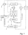
- Fig. 1 is a schematic view of a device according to the invention.
- Fig. 2 is a perspective view of a drying device according to an embodiment of the invention.
- Fig. 3 is a schematic view of a system comprising a drying device according to the invention.
- the drying device 1 comprises a cylindrical drying chamber 2, which is made of a material that does not absorb microwaves, such as plastic.
- the drying chamber 2 is surrounded, except at its top face, by a radiation-shielding metal cover (not shown).
- a number of, in this case two, air nozzles lead into the bottom of the chamber 2, and three microwave applicators/waveguides 17 lead into the side wall of the metal cover, said microwave applicators being connected to radiation-generating sources, in this case microwave-generating magnetrons 14 which are cooled by a cooling fan 15.
- the microwave applicators are uniformly distributed in the vertical direction of the chamber.
- the air nozzles 5 eject air at an angle, preferably about 30°, to the horizontal plane in mutually different directions, to cause cyclic rotation of the air. This results in a large contact surface between waste and air.
- the nozzles consist of plates covering the openings and have inclined (about 30°) through openings.
- a stirring means 4 is also arranged, which comprises a centrally rotationally arranged arm.
- the stirring means is connected to a motor and can be caused to rotate in the chamber at a speed of e.g. 10-20 revolutions per minute.
- the chamber is upwardly open but is closed with a lid 3, which also comprises a metal plate, to supplement the shielding metal cover.
- This plate together with the above-mentioned metal cover, surrounds the drying chamber 2 completely when the lid is closed, to provide complete shielding.
- an opening 6 which is covered with a perforated sheet 7 round the upper part of the drying chamber and through which the air leaves. From this top opening 6 extends a duct 16 leading to a condenser 9. After that the duct 16 extends via a fan 8 to an electric heater battery 12 and then finally leads to the above-described air nozzle 5 to form a closed circuit.
- the condenser 9 is further sealingly connected to a container 10 for condensate. This container can be emptied via a valve 11.
- a number of sensors S1, S2 are also arranged in the device.
- a first moisture sensor S1 is arranged before the condenser for the purpose of checking the moisture content of the outgoing flow of air.
- a second condenser is positioned before the nozzles at the chamber, for measuring the air temperature in the chamber.
- the sensors are connected to a control unit 18.
- the above-described units jointly form a closed circuit, or circulating system, in which the air can be circulated without coming into contact with the atmosphere during drying.
- the air in the system can have a speed of circulation of about 100 m 3 /h during drying.
- the waste When drying biological waste, such as remainders of fruit, fish, vegetables and meat, the waste is placed in the chamber 2, after which the lid 3 is closed and the chamber 2 is sealed. Conveniently the waste has been finely divided into pieces of uniform size before it was placed in the chamber 2. This can take place by means of a dividing device I which is located in connection with the drying device. This is schematically illustrated in Fig. 3.
- the dividing device also comprises an integrated screening table for screening the waste.
- a dividing device can be arranged for this purpose in the chamber. Subsequently the fan 16 is set into operation, and air begins to circulate in the system.
- the electric heater battery 12 is set into operation, which heats the air to a selected temperature, and later the air emits this heat to the waste in the chamber.
- the air is heated by the battery to a temperature of between about 50° and 150°C, preferably between 75° and 100°C, suitably about 80°C.
- the heating of the air results in an increase in its capacity of absorbing moisture. Thanks to the injection of hot air, waste in the chamber is thus heated.
- the magnetrons 14 are started at a relatively low effect, which gradually increases as the evaporation of moisture from the waste increases.
- the magnetron effect is kept at an even level until the moisture sensor S1 which is located before the condenser 9 indicates that the moisture content of the outgoing air decreases, after which the magnetron effect is gradually lowered until it reaches below a predetermined value, below which the magnetrons 14 are pulsed for 10-20 s/min until the moisture content of the flow of air reaches a preset value. Then the microwave radiation is interrupted while the fan 8 is allowed to operate for a further period of time, for the purpose of causing afterdrying of the waste.
- the above-mentioned sensors S1, S2 check the moisture content and the temperature in the different parts of the system, for the purpose of controlling the magnetron radiation and the electric heating and, thus, optimising the drying process while at the same time overheating of the system as well as the forming of liquid in the chamber are prevented.
- the air removes exactly all the moisture that is generated in microwave drying of the waste. If too large an amount of moisture is removed, there is a risk of the waste overheating, with the ensuing risk of fire. Therefore the device can also, as an additional measure of precaution, be provided with means for fire protection. If too small an amount of moisture is removed, liquid forms in the drying chamber 2, which results in an impaired drying result and greater time expenditure.
- the moist air forming in the chamber is exhausted through the perforated sheet 7 and into the duct and on to the condenser.
- the air is dehumidified in conventional manner. Before the condenser, the air can have a relative humidity of 20-100%. When the air is cooled in the condenser, the relative humidity increases to 100% and water is precipitated.
- the condensate is conveyed to the above-described condensate container 11 to be stored. After the condenser, the air is conveyed to the electric heater battery where the air is again heated and the relative humidity decreases to 15-25%, so as to be injected once more into the drying chamber.
- hot air is circulated through the chamber 2 in such manner that the waste in the chamber is rapidly heated and thus begins to emit vapour.
- the moisture content of the outgoing flow of air is monitored by means of the sensor S1 and/or S2.
- the sensor sends a signal to the stirring means 4, and stirring of the waste takes place for a predetermined period of time, after which the circulation of hot air continues.
- the circulation of air may also occur during the stirring. Owing to the stirring, the emitted amount of vapour from the waste probably increases after stirring. After stirring, the circulation of air continues until the moisture content of the outgoing flow of air once more falls below said predetermined value, and then stirring is started again.
- the units described above are arranged in a closed system, which means that there is no risk of smell or the like escaping, which makes the device suitable for use in, for instance, food shops and restaurants.
- the waste product from the above device forms flakes, so-called bioflakes.
- the bioflakes Owing to the drying process, in contrast to, for instance, pressing, the bioflakes retain the entire nutritional value that was present in the waste.
- the bioflakes are usable, for instance, as additives in e.g. fodder.
- the bioflakes can be used as additives in, for example, composting, digestion or combustion.
- the biological waste has been converted from waste into a useful product.
- a further advantage of the drying is that the volume and weight of the waste decrease to a considerable extent. In connection with animal waste, the volume after drying will be about 50% of the original and, in connection with vegetable waste, the volume amounts to about 10-20% of the original. The decreases in weight in each case are equivalent.
- the maximum moisture content is 10% in both cases. This also results in decreased transport charges.
- the waste is sanitised by being heated to min. 75° for at least one hour, during which pathogenic bacteria are killed.
- the bioflakes will have a storage life at room temperature of at least 6 months and are essentially odourless.
- This dried waste can be stored in an ordinary room. Conveniently the waste can be stored in vessels which are intended for transport.
- An exhausting device is suitably used to empty the chamber of dried waste into a storage container before new waste for drying can be supplied to the chamber. Thanks to the fact that the dried waste has a long storage life and is essentially odourless and sanitised, the dried waste can be collected using the same vehicle as delivers e.g. food, which results in changed and less expensive treatment of waste.
- a conventional packing machine can be arranged in connection with the drying device for direct packing of the bioflakes in bags or the like.
- the above-mentioned fan can be located in different positions in the system since its only purpose is to circulate the air in the closed circuit.
- the location of the sensors can be varied, and the sensors can be, for instance, temperature or moisture measuring means, depending on the design of the control box.
- the flow of air from the air nozzles makes an angle to the horizontal plane of about 30°. It goes without saying that this angle can be varied as regards the geometry of the chamber etc.
- the embodiment described above has also air nozzles for injection of air at the bottom of the chamber and air outlets at the top of the chamber.
- nozzles and outlets can be located in different positions in the chamber but are suitably, like in the above example, arranged on opposite sides of the chamber to produce a flow of air through essentially the entire chamber.
- the radiation sources described in the embodiments are microwave sources, more specifically magnetrons, but it is also possible to use radiation sources in certain other wavelength ranges, for instance in the infrared radiation range or the HF and VHF or EHF frequency bands, to provide a drying device with the desired properties in different situations.
- a condenser as the humidifying unit is described above, but this can be replaced by, for example, a compressor.
Landscapes
- Engineering & Computer Science (AREA)
- Chemical & Material Sciences (AREA)
- Mechanical Engineering (AREA)
- General Engineering & Computer Science (AREA)
- Microbiology (AREA)
- Ceramic Engineering (AREA)
- Life Sciences & Earth Sciences (AREA)
- Molecular Biology (AREA)
- Biotechnology (AREA)
- Biomedical Technology (AREA)
- Health & Medical Sciences (AREA)
- Materials Engineering (AREA)
- Structural Engineering (AREA)
- Organic Chemistry (AREA)
- Processing Of Solid Wastes (AREA)
- Dispersion Chemistry (AREA)
- Drying Of Solid Materials (AREA)
- Physics & Mathematics (AREA)
- Plasma & Fusion (AREA)
Applications Claiming Priority (2)
| Application Number | Priority Date | Filing Date | Title |
|---|---|---|---|
| SE0001806A SE520713C2 (sv) | 2000-05-17 | 2000-05-17 | Anordning, förfarande och system för torkning av biologiskt avfall |
| SE0001806 | 2000-05-17 |
Publications (2)
| Publication Number | Publication Date |
|---|---|
| EP1156292A2 true EP1156292A2 (de) | 2001-11-21 |
| EP1156292A3 EP1156292A3 (de) | 2002-04-17 |
Family
ID=20279691
Family Applications (1)
| Application Number | Title | Priority Date | Filing Date |
|---|---|---|---|
| EP01111828A Withdrawn EP1156292A3 (de) | 2000-05-17 | 2001-05-16 | Vorrichtung zur Behandlung von biologischen Abfällen |
Country Status (2)
| Country | Link |
|---|---|
| EP (1) | EP1156292A3 (de) |
| SE (1) | SE520713C2 (de) |
Cited By (3)
| Publication number | Priority date | Publication date | Assignee | Title |
|---|---|---|---|---|
| EP1528341A2 (de) * | 2003-10-27 | 2005-05-04 | Egbert Nensel | Verfahrensweise zum Trocknen mittels Infrarotstrahlen |
| WO2006130072A1 (en) * | 2005-05-30 | 2006-12-07 | Gisip Innovations Ab | Method and means for drying using microwaves |
| EP1847791A1 (de) * | 2006-04-21 | 2007-10-24 | Bearn Innovation | Verfahren zur Trocknung von Schlämmen und Vorrichtung zur Durchführung dieses Verfahrens |
Citations (9)
| Publication number | Priority date | Publication date | Assignee | Title |
|---|---|---|---|---|
| EP0312741A2 (de) * | 1987-08-29 | 1989-04-26 | Nissui Kako Co., Ltd. | Verfahren und Vorrichtung zur Mikrowellentrocknung von Kunststoff |
| DE4119149A1 (de) * | 1991-03-22 | 1992-11-05 | Hak Anlagenbau Gmbh Fuer Verfa | Verfahren zur entfernung verdampfungsfaehiger stoffe und anlage zur durchfuehrung des verfahrens |
| EP0619149A1 (de) * | 1993-04-09 | 1994-10-12 | Matsushita Electric Industrial Co., Ltd. | Müllbehandlungsvorrichtung |
| EP0620054A1 (de) * | 1993-04-12 | 1994-10-19 | Matsushita Electric Industrial Co., Ltd. | Müllbehandlungsvorrichtung |
| JPH08178522A (ja) * | 1994-12-19 | 1996-07-12 | Hitachi Ltd | 乾燥装置 |
| JPH08299943A (ja) * | 1995-04-30 | 1996-11-19 | Bridgestone Corp | 生ごみ処理機 |
| EP0814311A1 (de) * | 1996-06-20 | 1997-12-29 | Colortronic GmbH | Verfahren und Vorrichtung zum Trocknen |
| WO1998053711A1 (en) * | 1997-05-28 | 1998-12-03 | Australian Rural Dehydration Enterprise Pty. Ltd. | Dehydration plant |
| EP0924488A1 (de) * | 1997-12-16 | 1999-06-23 | Paloma Industries, Ltd. | Abfallbeseitiger |
-
2000
- 2000-05-17 SE SE0001806A patent/SE520713C2/sv not_active IP Right Cessation
-
2001
- 2001-05-16 EP EP01111828A patent/EP1156292A3/de not_active Withdrawn
Patent Citations (9)
| Publication number | Priority date | Publication date | Assignee | Title |
|---|---|---|---|---|
| EP0312741A2 (de) * | 1987-08-29 | 1989-04-26 | Nissui Kako Co., Ltd. | Verfahren und Vorrichtung zur Mikrowellentrocknung von Kunststoff |
| DE4119149A1 (de) * | 1991-03-22 | 1992-11-05 | Hak Anlagenbau Gmbh Fuer Verfa | Verfahren zur entfernung verdampfungsfaehiger stoffe und anlage zur durchfuehrung des verfahrens |
| EP0619149A1 (de) * | 1993-04-09 | 1994-10-12 | Matsushita Electric Industrial Co., Ltd. | Müllbehandlungsvorrichtung |
| EP0620054A1 (de) * | 1993-04-12 | 1994-10-19 | Matsushita Electric Industrial Co., Ltd. | Müllbehandlungsvorrichtung |
| JPH08178522A (ja) * | 1994-12-19 | 1996-07-12 | Hitachi Ltd | 乾燥装置 |
| JPH08299943A (ja) * | 1995-04-30 | 1996-11-19 | Bridgestone Corp | 生ごみ処理機 |
| EP0814311A1 (de) * | 1996-06-20 | 1997-12-29 | Colortronic GmbH | Verfahren und Vorrichtung zum Trocknen |
| WO1998053711A1 (en) * | 1997-05-28 | 1998-12-03 | Australian Rural Dehydration Enterprise Pty. Ltd. | Dehydration plant |
| EP0924488A1 (de) * | 1997-12-16 | 1999-06-23 | Paloma Industries, Ltd. | Abfallbeseitiger |
Non-Patent Citations (2)
| Title |
|---|
| PATENT ABSTRACTS OF JAPAN vol. 1996, no. 11, 29 November 1996 (1996-11-29) & JP 08 178522 A (HITACHI LTD), 12 July 1996 (1996-07-12) * |
| PATENT ABSTRACTS OF JAPAN vol. 1997, no. 03, 31 March 1997 (1997-03-31) & JP 08 299943 A (BRIDGESTONE CORP), 19 November 1996 (1996-11-19) * |
Cited By (7)
| Publication number | Priority date | Publication date | Assignee | Title |
|---|---|---|---|---|
| EP1528341A2 (de) * | 2003-10-27 | 2005-05-04 | Egbert Nensel | Verfahrensweise zum Trocknen mittels Infrarotstrahlen |
| EP1528341A3 (de) * | 2003-10-27 | 2008-06-18 | Egbert Nensel | Verfahrensweise zum Trocknen mittels Infrarotstrahlen |
| WO2006130072A1 (en) * | 2005-05-30 | 2006-12-07 | Gisip Innovations Ab | Method and means for drying using microwaves |
| EP1847791A1 (de) * | 2006-04-21 | 2007-10-24 | Bearn Innovation | Verfahren zur Trocknung von Schlämmen und Vorrichtung zur Durchführung dieses Verfahrens |
| FR2900224A1 (fr) * | 2006-04-21 | 2007-10-26 | Bearn Innovation Bernard Dedie | Procede de sechage des boues et dispositif permettant la mise en oeuvre du procede |
| WO2007122328A1 (fr) * | 2006-04-21 | 2007-11-01 | Bearn Innovation - Dedieu Bernard | Procédé de séchage des boues et dispositif permettant la mise en oeuvre du procédé |
| AU2007242682B2 (en) * | 2006-04-21 | 2011-12-22 | INNOTHERM-E Technologies | Method of drying sludge and device for implementing the method |
Also Published As
| Publication number | Publication date |
|---|---|
| EP1156292A3 (de) | 2002-04-17 |
| SE520713C2 (sv) | 2003-08-12 |
| SE0001806L (sv) | 2001-11-18 |
| SE0001806D0 (sv) | 2000-05-17 |
Similar Documents
| Publication | Publication Date | Title |
|---|---|---|
| US7966744B2 (en) | Food waste treatment apparatus using microwave | |
| EP3216777B1 (de) | Verfahren zum betreiben einer kompostervorrichtung und kompostervorrichtung | |
| JPH04500765A (ja) | 危険性医療廃棄物を処理する装置および方法 | |
| CA2994390C (en) | Organic waste digester system | |
| EP3287417B1 (de) | Verfahren und vorrichtung zur verhinderung von schimmelwuchs im behälter eines lebensmittelabfallrecyclinggeräts | |
| KR101322303B1 (ko) | 음식물류폐기물의 종량제 수거 및 자원화 장치 | |
| CA3219355A1 (en) | Microwave waste heating system and related features | |
| JP2001082873A (ja) | 乾燥装置及びその乾燥方法 | |
| US3626838A (en) | Continuous microwave grain cooker | |
| EP0545520A1 (de) | Sterilisiergerät für medizinischen Abfall | |
| EP1156292A2 (de) | Vorrichtung zur Behandlung von biologischen Abfällen | |
| KR101455028B1 (ko) | 이동식 축분 펠릿 제조시스템 | |
| US20080083749A1 (en) | Method and apparatus for the dehydration and/or sterilization of organic materials | |
| EP2059264A1 (de) | Verfahren und gerät zur dehydration und/oder sterilisation von organischen stoffen | |
| TWI693114B (zh) | 用於處理混合廢料的裝置及其方法 | |
| JP2001293452A (ja) | 生ゴミ乾燥処理方法、生ゴミ乾燥処理装置及び生ゴミの肥料化方法 | |
| EP1157250A1 (de) | Verfahren und anlage zur hygienisierung und trocknung von organischen abfällen | |
| KR101826973B1 (ko) | 음식물쓰레기 처리장치 | |
| KR200158821Y1 (ko) | 음식물쓰레기 처리장치 | |
| KR101850402B1 (ko) | 음식물쓰레기 처리기용 열풍공급장치 | |
| KR20100100313A (ko) | 음식물 쓰레기 처리장치 | |
| EP1874491A1 (de) | Mikrowellen verwendende vorrichtung zur behandlung von lebensmittelabfällen | |
| JP2002096049A (ja) | 生ごみ処理方法および装置 | |
| KR20110037215A (ko) | 고주파 및 열매체유를 이용한 건조장치 | |
| GB2320247A (en) | Treating materials, especially medical wastes |
Legal Events
| Date | Code | Title | Description |
|---|---|---|---|
| PUAI | Public reference made under article 153(3) epc to a published international application that has entered the european phase |
Free format text: ORIGINAL CODE: 0009012 |
|
| AK | Designated contracting states |
Kind code of ref document: A2 Designated state(s): AT BE CH CY DE DK ES FI FR GB GR IE IT LI LU MC NL PT SE TR |
|
| AX | Request for extension of the european patent |
Free format text: AL;LT;LV;MK;RO;SI |
|
| PUAL | Search report despatched |
Free format text: ORIGINAL CODE: 0009013 |
|
| AK | Designated contracting states |
Kind code of ref document: A3 Designated state(s): AT BE CH CY DE DK ES FI FR GB GR IE IT LI LU MC NL PT SE TR |
|
| AX | Request for extension of the european patent |
Free format text: AL;LT;LV;MK;RO;SI |
|
| 17P | Request for examination filed |
Effective date: 20021016 |
|
| AKX | Designation fees paid |
Free format text: AT BE CH CY DE DK ES FI FR GB GR IE IT LI LU MC NL PT SE TR |
|
| 17Q | First examination report despatched |
Effective date: 20040413 |
|
| STAA | Information on the status of an ep patent application or granted ep patent |
Free format text: STATUS: THE APPLICATION IS DEEMED TO BE WITHDRAWN |
|
| 18D | Application deemed to be withdrawn |
Effective date: 20041026 |