EP1156005A2 - Falztasche - Google Patents
Falztasche Download PDFInfo
- Publication number
- EP1156005A2 EP1156005A2 EP01107771A EP01107771A EP1156005A2 EP 1156005 A2 EP1156005 A2 EP 1156005A2 EP 01107771 A EP01107771 A EP 01107771A EP 01107771 A EP01107771 A EP 01107771A EP 1156005 A2 EP1156005 A2 EP 1156005A2
- Authority
- EP
- European Patent Office
- Prior art keywords
- stop
- threaded spindle
- folding
- folding pocket
- Prior art date
- Legal status (The legal status is an assumption and is not a legal conclusion. Google has not performed a legal analysis and makes no representation as to the accuracy of the status listed.)
- Withdrawn
Links
- 230000033001 locomotion Effects 0.000 claims abstract description 20
- 230000005540 biological transmission Effects 0.000 description 7
- 230000008878 coupling Effects 0.000 description 5
- 238000010168 coupling process Methods 0.000 description 5
- 238000005859 coupling reaction Methods 0.000 description 5
- 230000002441 reversible effect Effects 0.000 description 2
- 238000011161 development Methods 0.000 description 1
- 230000018109 developmental process Effects 0.000 description 1
- 238000005259 measurement Methods 0.000 description 1
- 238000000034 method Methods 0.000 description 1
- 230000002035 prolonged effect Effects 0.000 description 1
Images

Classifications
-
- B—PERFORMING OPERATIONS; TRANSPORTING
- B65—CONVEYING; PACKING; STORING; HANDLING THIN OR FILAMENTARY MATERIAL
- B65H—HANDLING THIN OR FILAMENTARY MATERIAL, e.g. SHEETS, WEBS, CABLES
- B65H45/00—Folding thin material
- B65H45/12—Folding articles or webs with application of pressure to define or form crease lines
- B65H45/14—Buckling folders
- B65H45/142—Pocket-type folders
- B65H45/144—Pockets or stops therefor
Definitions
- the invention relates to a folding pocket according to the preamble of claim 1.
- DD 287012 A5 is already a folding pocket with a device for setting the position of the pocket stop known. It is proposed on both sides provide a rope and an associated cable shaft of the pocket stop, the can be moved independently so that each side of the pocket stop can be positioned independently of the other. The rotation of each of the Cable shafts are carried out with the help of an actuator, which is an incremental encoder assigned.
- an actuator which is an incremental encoder assigned.
- the object of the present invention is therefore to provide a folding pocket with an improved Propose device for adjusting the position of the pocket stop with the a defined inclination of the stop can be achieved and also with a longer one Use a rigid guidance of the pocket stop is guaranteed.
- Two threaded spindles that face each other relative to the center of the stop are each preferably connected to the respective ends of the pocket stop, ensure a rigid guidance of the pocket stop on both sides, so that one unwanted inclination and inaccurate positioning of the pocket stop is avoided.
- the additionally provided coupling of the two threaded spindles ensures the possibility of a simultaneous and coordinated Movement of both sides of the pocket stop.
- the Coupling of the two threaded spindles can be carried out mechanically, the motor the first threaded spindle via a drive element with the second threaded spindle is connected so that the motor of the first threaded spindle is both the first Screws as well as the second screw drives.
- both threaded spindles to couple electrically with each other and individually to each of the threaded spindles Motor, in particular to provide a servo motor.
- the two motors are over an electrical or electronic control unit coupled so that a simultaneous coordinated movement of both spindles and thus both ends of the pocket stop is made possible.
- both motors can be controlled in such a way that a simultaneous movement of the pocket stop in or against the paper running direction can be done.
- the motors can also be controlled via the control unit that both cause the spindles to move in opposite directions, so that one defined inclination of the pocket stop is reached.
- the control unit also stops a motor while moving the other motor too.
- the inclination of the pocket stop can also by moving the spindles in the same direction but differently Speed can be achieved.
- This movement is also coupled by a reached two motors via the control unit, the control unit Relative movement of the motors controls each other.
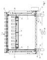
- FIG. 1 shows a folding pocket 10 according to the invention with a pocket stop 12
- Fold length of a folded sheet entering direction A is determined by the position of the Fold pocket stop 12 determined within the pocket. Accordingly, the To adjust the fold length, the fold pocket stop 12 is positioned within the fold pocket.
- 14 threaded spindles 16, 17 are arranged symmetrically to its center and coupled to the folding pocket. Although this coupling is made by connecting the Threaded spindles 16, 17 would be possible per se by the folding pocket stop 12 this will limit the width of the foldable sheet. Therefore, as in Figure 1 shown, the threaded spindle 16, 17 on an outer edge 20, 21 of the Pocket stop 12 coupled.
- the threaded spindles 16, 17 connected to the pocket stop 12 via spindle nuts 22, 23.
- the connections the threaded spindles for the pocket stop are advantageously articulated and executed without play, so that the pocket stop 12 when the Threaded spindles 16, 17 are guided rigidly and without play via the threaded nuts 22, 23.
- the movement of the threaded spindles 16, 17 is generated by drive units 31, 32, which can be started up independently of each other.
- drive units 31, 32 can each have a stepper motor 24, 26 have.
- the stepper motors 24, 26 are with their drive shafts directly to the Threaded spindles 16, 17 coupled.
- the drive units 31, 32 can each have one Servo motor 24, 26, one transmission gear 25, 27 each between the motor output shaft and threaded spindle 16, 17 and a rotary encoder 39, 40, z. B. one Have incremental encoders. Via the respective measurement signal of the rotary encoder 39, 40 respective actual position of the spindle nuts 22, 23 and thus of the pocket stop 12 determined and transmitted to the controller 28. To move to a new target position of the Pocket stop 12, the controller 28 determines the required direction of rotation Servomotors 24, 26 and controls them until the signals from the encoders Report back when the respective setpoint is reached.
- the encoder 39, 40 preferably as a hollow shaft encoder on the output shaft of the Transmission gear 25, 27 arranged. This advantageous arrangement allows that the transmission output shaft continues directly to the respective end of the threaded spindle 16, 17 can be coupled.
- the measured value of the rotary encoder 39, 40 thus always represents exactly the rotational position of the threaded spindle 16, 17 and thus the position of the Pocket stop 12.
- the direction of rotation of both motors 24, 26 is reversible, so that the threaded spindles 16, 17 can be set clockwise and counterclockwise and corresponding to the stop 12 in the paper feed direction, d. H. in the direction of arrow A, or can be moved against the paper feed direction.
- the first threaded spindle 16 is via the first motor 24 with the second threaded spindle 17 via the second motor 26 connected, the connection between the motors 24, 26 via a control unit 28 he follows.
- the control unit 28 is able to match both motors in this way control a coordinated movement of the first 21 and second 22 sides the pocket stop via a coordinated movement of the first Threaded spindle 16 and the second threaded spindle 17 is made possible.
- the control unit 28 can simultaneously move the motor 24, 26 in the same direction, d. H. to be caused on both sides in or on both sides against the paper inlet direction A. So that the paper stopper 12 on both sides in or against the The paper feed direction is set so that the desired fold length is set. This assumes, however, that the control unit 28 also the rotational speed of the two Motors 24, 26 are adjusted so that one another on both sides of the stop 12 Movement takes place by the same amount.
- the control device 28 can, for example control the motors 24, 26 so that the two motors with different Rotation speed act on the threaded spindles 16, 17, so that, for example Threaded spindle 16 is rotated less times per unit of time than the threaded spindle 17.
- both threaded spindles 16, 17 are rotated in the same direction, this has to Consequence that the spindle nut 22 is moved more slowly than the spindle nut 23 and the Correspondingly, spindle nut 23 travels a larger distance in the same time unit. This procedure ensures that the pocket stop 12 is inclined is, which again proves to be particularly advantageous if the threaded spindles 22, 23 articulated and free of play with the outer edges 20, 21 of the folding pocket stop 12 are connected.
- An inclined position of the pocket stop 12 is also possible in that the Control unit 28 acts on the motors 24, 26 in a manner which is the same Rotational speed an opposite rotation of the spindles 16, 17 causes, so that the pocket stop 12 rotated about a virtual center 14 becomes.
- This in turn has the advantage of changing the length setting can be dispensed with if an additional slight inclination of the Pocket stop to compensate for an inclined edge of the incoming folding product must be set.
- the pocket stop 12 is inclined the control device 28 a rotational movement of the pocket stop 12 in that first both motors 24, 26 are controlled so that the spindles 16, 17 turn evenly in the same direction to achieve a parallel basic setting in the to achieve the correct fold length.
- a possible oblique edge of the incoming sheet of paper can now be corrected by following it the control unit 28 controls one of the motors 24, 26 and in or against Paper direction rotates while the other motor sends a control signal from the control unit 28 receives that causes no rotation of the motor.
- an additional processing unit 30 are provided, which with the Control unit 28 is connected.
- this processing unit 30 enables Preset the pocket stop depending on the desired location or desired Angle as well as the processing of sensor signals, which allow an exact positioning of the Allow pocket stop 12.
- the processing unit 30 can be used to after entering a standardized fold type and the sheet format on a control panel Setting values of several pocket stops in one or more folding units calculate and transmit to the control unit 28.
- the can continue Processing unit 30 can be used to store setting values. These values can be called up again if necessary and transmitted to the control unit 28.
- Control unit 28 can also be integrated there.
- FIG. 2 Another embodiment of the folding pocket according to the invention is shown in FIG. 2.
- a pocket stop 12 is arranged for a in the arrow direction A incoming folding sheet and the position of the folding length certainly.
- the pocket stop 12 is at its two lateral ends 21, 22, respectively via a spindle nut 22, 23 also arranged in the folding pocket Threaded spindles 16, 17 connected.
- this connection is preferably articulated and free of play so that a exact positioning of the pocket stop is possible.
- the spindle nuts 22, 23 move the pocket stop 12 when the threaded spindles 16, 17 rotate according to the respective direction of rotation of the threaded spindle in or against the Paper feed direction A.
- the first threaded spindle is 16 coupled to the second threaded spindle 17 via a toothed belt 34 which is on the first Side, i.e. on the side of the first threaded spindle 16, with a drive unit 32 connected is.
- the drive unit 32 can, as in the first embodiment described, either consist of a stepper motor 33 or from an arrangement Servo motor, transmission gear and hollow shaft encoder.
- the functions of Drive unit 32 in the mentioned embodiments is in the embodiment according to the figure 2 in principle identical to that already described for embodiment 1 in FIG. 1.
- the second side of the toothed belt 34 with a second drive element 36 is the second Threaded spindle 17 connected.
- the second drive element 36 has none own engine on.
- the second threaded spindle 17 is driven via the on the first drive element 32 driven toothed belt 34, which thus also Rotary motion to the second drive element 36 transmits.
- this mechanical Coupling the two threaded spindles it is now possible to create a coordinated one Perform movement of the threaded spindles, because the threaded spindles are so together are mechanically coupled that the motor 33 of the first drive element 32 both the first threaded spindle 16 as well as the second threaded spindle 17 can drive.
- the two Threaded spindles 16, 17 are decoupled from one another for the time of the inclination. This can happen, for example, in that one in the drive unit 36 second threaded spindle 17 existing clamping screw 38 is loosened. By the On the one hand, opening the clamping screw 38 causes the first threaded spindle 16 is mechanically decoupled from the second threaded spindle 17 and that continues to one the second drive unit 36 attached outer ring can be rotated.
- This outer ring is connected directly to the spindle axis of the second spindle 17, so that a Rotation of the outer ring is transmitted directly to the spindle. So that can Rotation of the outer ring reaches an inclined position of the pocket stop 12 become. After setting the desired inclination, the clamping screw 38 tightened again so that the pocket stop 12 is not during the folding operation can be adjusted further. With this fixation, the pocket stop 12 can be over the Maintain the exact position of both threaded spindles.
- the proposed folding pocket improves precise guidance and enables an exact one Setting a predetermined position and a desired inclination of the Pocket stop 12.
- operational safety against wear is clear improved because the threaded spindles are running in at high speed Folded sheets can offer more resistance than, for example, those previously timing belt used.
Landscapes
- Folding Of Thin Sheet-Like Materials, Special Discharging Devices, And Others (AREA)
Abstract
Description
- Fig. 1
- eine erfindungsgemäße Einstellvorrichtung des Taschenanschlages mit zwei Gewindespindeln und je einem Motor,
- Fig. 2
- eine erfindungsgemäße Einstellvorrichtung des Taschenanschlages mit zwei Gewindespindeln, einem Motor und einem mechanischen Antriebsglied
- 10
- Falztasche
- 12
- Taschenanschlag
- 14
- Mitte des Taschenanschlages
- 16
- Gewindespindel
- 17
- Gewindespindel
- 20
- Außenkante des Taschenanschlages
- 21
- Außenkante des Taschenanschlages
- 22
- Spindelmutter
- 23
- Spindelmutter
- 24
- erster Motor
- 25
- Übersetzungsgetriebe
- 26
- zweiter Motor
- 27
- Übersetzungsgetriebe
- 28
- Steuereinheit
- 30
- Verarbeitungseinheit
- 31
- Antriebseinheit
- 32
- Antriebseinheit
- 33
- Motor
- 34
- Zahnriemen
- 36
- Antriebselement
- 38
- Klemmschraube
- 39
- Drehgeber
- 40
- Drehgeber
Claims (18)
- Falztasche (10) mit einem in ihr liegenden Taschenanschlag (12), der im wesentlichen quer zur Papierlaufrichtung (7) angeordnet ist, und einer Antriebseinheit (32) zum Verstellen der Position des Taschenanschlages (12) innerhalb der Falztasche (10),
gekennzeichnet durch
eine erste Gewindespindel (16), die mit einer ersten Seite (21) des Taschenanschlages (12) verbunden ist und diese starr führt und eine zweite Gewindespindel (17), die mit einer zweiten Seite (22) des Taschenanschlages verbunden ist und diese starr führt, wobei die erste Gewindespindel (16) mit der Antriebseinheit (32) verbunden ist, die eine Drehbewegung der Gewindespindel (16) erzeugen kann und die erste (16) und die zweite (17) Gewindespindel so miteinander gekoppelt sind, dass eine abgestimmte Bewegung der ersten (21) und zweiten (22) Seite des Taschenanschlages (12) möglich ist. - Falztasche nach Anspruch 1,
dadurch gekennzeichnet, dass die zweite Gewindespindel (17) eine zweite Antriebeinheit (31) aufweist und die beiden Spindeln (16, 17) über eine elektrische Steuereinheit miteinander gekoppelt sind, so dass die Abstimmung der Bewegung der ersten (21) und zweiten (22) Seite des Taschenanschlages über eine elektrische Steuerung der motorischen Verstelleinrichtungen (24, 26) erfolgt. - Falztasche nach Anspruch 2,
dadurch gekennzeichnet, dass wenigstens eine der Antriebseinheiten (31, 32) eine motorische Verstelleinrichtungen (24, 26, 33) aufweist. - Falztasche nach Anspruch 3,
dadurch gekennzeichnet, dass die motorische Verstelleinrichtung (24, 26, 33) ein Servomotor ist. - Falztasche nach Anspruch 3,
dadurch gekennzeichnet, dass die motorische Verstelleinrichtung (24, 26, 33) ein Schrittmotor ist. - Falztasche nach Anspruch 4,
dadurch gekennzeichnet, dass wenigstens eine der Antriebseinheiten (31, 32) einen Drehgeber aufweist. - Falztasche nach Anspruch 6,
dadurch gekennzeichnet, dass der Drehgeber als Hohlwellendrehgeber ausgeführt ist. - Falztasche nach einem der Ansprüche 2 bis 7,
dadurch gekennzeichnet, dass die Motoren (24, 26) mit der Steuereinheit (28) so gekoppelt sind, dass sie gegenläufig ansteuerbar sind, so dass der Taschenanschlag (12) um einen Punkt (14) drehbar ist, der in der Mitte zwischen den Verbindungspunkten der ersten (16) und zweiten (17) Gewindespindel entlang des Taschenanschlages (12) liegt. - Falztasche nach einem der Ansprüche 2 bis 7,
dadurch gekennzeichnet, dass die motorischen Verstelleinrichtungen (24, 26) mit der Steuereinheit (28) so gekoppelt sind, dass eine Schrägstellung des Taschenanschlages (12) dadurch erreicht werden kann, dass einer der Motoren (24) so angesteuert wird, dass er still steht, während der andere Motor (26) so angesteuert wird, dass er sich bewegt. - Falztasche nach Anspruch 8 oder 9,
dadurch gekennzeichnet, dass die Verbindung zwischen jeder der Gewindespindeln (16, 17) und dem Taschenanschlag (12) gelenkig und spielfrei ausgeführt ist. - Falztasche nach einem der Ansprüche 1 bis 10,
dadurch gekennzeichnet, dass jede der Gewindespindeln (16, 17) oder jeder der Motoren (24, 26) ein Meßelement aufweist, das die genaue Position des Taschenanschlages (12) erfassen kann. - Falztasche nach Anspruch 11,
dadurch gekennzeichnet, dass weiterhin eine Verarbeitungseinrichtung (30), insbesondere ein Mikrokontroller oder SPS vorgesehen ist, an den die Meßsignale der Meßelemente weitergegeben und dort angezeigt oder verarbeitet werden können. - Falztasche nach Anspruch 12,
dadurch gekennzeichnet, dass die Verarbeitungseinrichtung (30) so ausgeführt ist, dass sie ihrerseits Signale an die elektrische Steuereinheit (28) weitergeben kann um eine Voreinstellung des Taschenanschlages (12) nach Lage und Winkel zu ermöglichen. - Falztasche nach einem der Ansprüche 1 bis 13,
dadurch gekennzeichnet, dass die elektrische Steuereinheit (28) so ausgerührt ist, dass sie zur Positionierung des Taschenanschlages (12) einen oder beide der Motoren (24, 26) ansteuern kann. - Falztasche nach Anspruch 1,
dadurch gekennzeichnet, dass die erste Gewindespindel (16) mit der zweiten Gewindespindel (17) über ein Antriebselement (34) verbunden ist, das von dem Motor der ersten Gewindespindel angetrieben wird. - Falztasche nach Anspruch 15,
dadurch gekennzeichnet, dass das Antriebselement (34) ein Zahnriemen ist. - Falztasche nach Anspruch 15 oder 16,
dadurch gekennzeichnet, dass die zweite Gewindespindel (17) eine Vorrichtung zum Entkoppeln (38) der Gewindespindel (17) von dem Antriebselement (34) aufweist. - Falztasche nach Anspruch 17,
dadurch gekennzeichnet, dass die zweite Gewindespindel (17) manuell drehbar ist, so dass im entkoppelten Zustand eine einseitige Bewegung des Taschenanschlages (12) und damit eine Schrägstellung des Taschenanschlages (12) relativ zur Papierlaufrichtung (7) eingestellt werden kann.
Applications Claiming Priority (2)
| Application Number | Priority Date | Filing Date | Title |
|---|---|---|---|
| DE10023933 | 2000-05-17 | ||
| DE10023933A DE10023933A1 (de) | 2000-05-17 | 2000-05-17 | Falztasche |
Publications (2)
| Publication Number | Publication Date |
|---|---|
| EP1156005A2 true EP1156005A2 (de) | 2001-11-21 |
| EP1156005A3 EP1156005A3 (de) | 2004-01-21 |
Family
ID=7642233
Family Applications (1)
| Application Number | Title | Priority Date | Filing Date |
|---|---|---|---|
| EP01107771A Withdrawn EP1156005A3 (de) | 2000-05-17 | 2001-04-04 | Falztasche |
Country Status (4)
| Country | Link |
|---|---|
| US (1) | US20010044367A1 (de) |
| EP (1) | EP1156005A3 (de) |
| JP (1) | JP2002020032A (de) |
| DE (1) | DE10023933A1 (de) |
Families Citing this family (6)
| Publication number | Priority date | Publication date | Assignee | Title |
|---|---|---|---|---|
| DE10132910A1 (de) * | 2001-06-28 | 2003-01-16 | Baeuerle Gmbh Mathias | Falzvorrichtung für Bogen aus Papier, Kunststoff und dergleichen |
| DE102004058647A1 (de) | 2004-12-06 | 2006-06-14 | Heidelberger Druckmaschinen Ag | Vorrichtung zum Falzen flacher Werkstücke |
| JP5742284B2 (ja) * | 2011-02-21 | 2015-07-01 | 株式会社リコー | 折り装置及び画像形成システム |
| DE102012207038B4 (de) * | 2012-04-27 | 2014-07-10 | Maschinenbau Oppenweiler Binder Gmbh & Co. Kg | Falztaschenvorrichtung für eine Taschenfalzmaschine |
| CN110216921A (zh) * | 2019-06-26 | 2019-09-10 | 安徽文博纸品印刷有限公司 | 一种纸品加工用压缩装置 |
| DE102023102431A1 (de) * | 2023-02-01 | 2024-08-01 | Multivac Sepp Haggenmüller Se & Co. Kg | Lebensmittelverarbeitungsmaschine mit Diagnosesystem und Verfahren |
Family Cites Families (7)
| Publication number | Priority date | Publication date | Assignee | Title |
|---|---|---|---|---|
| GB248383A (en) * | 1925-03-02 | 1926-07-15 | Georg Spiess | Improvements in sheet-folding machines |
| DE2427850A1 (de) * | 1974-06-10 | 1975-12-18 | Oppenweiler Gmbh Maschinenbau | Falztasche |
| DE2738689C3 (de) * | 1977-08-27 | 1981-05-21 | Mathias Bäuerle GmbH, 7742 ST. Georgen | Stauchfalzmaschine mit Falztaschen |
| DE3544495A1 (de) * | 1985-12-17 | 1987-06-25 | Fritz Steffen | Falzmaschine mit automatischer anschlaganpassung |
| DD248344B1 (de) * | 1986-04-21 | 1989-08-09 | Polygraph Leipzig | Einstellvorrichtung fuer falztaschen |
| DD287012A5 (de) * | 1989-08-14 | 1991-02-14 | Veb Kombinat Polygraph "Werner Lamberz",De | Einrichtung zum verstellen von falztaschenanschlaegen |
| DE9402214U1 (de) * | 1994-02-10 | 1994-03-31 | Kodak Ag, 70327 Stuttgart | Vorrichtung zum Falzen von Blättern |
-
2000
- 2000-05-17 DE DE10023933A patent/DE10023933A1/de not_active Withdrawn
-
2001
- 2001-04-04 EP EP01107771A patent/EP1156005A3/de not_active Withdrawn
- 2001-05-17 JP JP2001147907A patent/JP2002020032A/ja active Pending
- 2001-05-17 US US09/859,796 patent/US20010044367A1/en not_active Abandoned
Also Published As
| Publication number | Publication date |
|---|---|
| DE10023933A1 (de) | 2001-11-22 |
| JP2002020032A (ja) | 2002-01-23 |
| EP1156005A3 (de) | 2004-01-21 |
| US20010044367A1 (en) | 2001-11-22 |
Similar Documents
| Publication | Publication Date | Title |
|---|---|---|
| DE3542923C2 (de) | ||
| EP0181593A1 (de) | Gelenkantrieb, insbesondere für Industrieroboter | |
| CH639308A5 (de) | Verfahren und einrichtung zur orientierung der drahtfuehrungskoepfe an funkenerosiven schneidanlagen zum erodieren mit grosser schraeglage des drahtes. | |
| DE4103160A1 (de) | Falzapparat mit einer vorrichtung zum verstellen von verstellbaren elementen eines falzwerkzylinders | |
| DE19747997A1 (de) | Taschenfalzwerk und Verfahren zur Registerregelung eines Taschenfalzwerks | |
| DE3309249A1 (de) | Vorrichtung zum verschieben eines schlittens od.dgl. an einem bett od.dgl. | |
| EP0864524A1 (de) | Kabeltransporteinheit | |
| DE3030432A1 (de) | Programmierte schweissmaschine mit geschwindigkeitsuebersetzung fuer den schweisskopf | |
| EP0193749B1 (de) | Mechanische Linearantriebseinheit | |
| DE3689352T2 (de) | Umdrehungssteuerung für ein Differentialstellglied. | |
| WO2008037734A1 (de) | Antriebssystem mit hohlwellenmotor und getriebe | |
| EP0263947B1 (de) | Maschine zum Läppen von zwei bogenverzahnten Kegelrädern | |
| DE10023933A1 (de) | Falztasche | |
| EP0302489A2 (de) | Falzapparat | |
| DE1605363C3 (de) | Vorrichtung an einem zur Messung, Registrierung und/oder Korrektur der Lage von Gleisen dienenden Fahrzeug, insbesondere Gleisrichtmaschine | |
| EP0585563B1 (de) | Vorrichtung zur Erzeugung von synchronen Schub-/Drehbewegungen | |
| EP2475497B1 (de) | Rundschalttisch | |
| EP0742061B1 (de) | Electronisch geregelte Windeeinrichtung für Matratzen- und Polsterfedern | |
| DE3441364C2 (de) | ||
| WO2009030210A1 (de) | Werkzeugkopf | |
| DE2920701C2 (de) | Halterung für eine Wendestange in einer Druckmaschine | |
| EP1436449A1 (de) | Antrieb für streckwerke einer spinnereimaschine | |
| DE102006032443B4 (de) | Vorrichtung zum Positionieren und Adapter zum Anschließen eines Werkzeugs oder eines Werkstücks | |
| DE19843575B4 (de) | Mehrspindelige Werkzeugmaschine, insbesondere Mehrspindeldrehautomat | |
| DE69801881T2 (de) | Vorrichtung zum Schneiden von geschmolzene Glastropfen aus dem Speiser einer Glasfertigungsmaschine |
Legal Events
| Date | Code | Title | Description |
|---|---|---|---|
| PUAI | Public reference made under article 153(3) epc to a published international application that has entered the european phase |
Free format text: ORIGINAL CODE: 0009012 |
|
| AK | Designated contracting states |
Kind code of ref document: A2 Designated state(s): AT BE CH CY DE DK ES FI FR GB GR IE IT LI LU MC NL PT SE TR |
|
| AX | Request for extension of the european patent |
Free format text: AL;LT;LV;MK;RO;SI |
|
| PUAL | Search report despatched |
Free format text: ORIGINAL CODE: 0009013 |
|
| AK | Designated contracting states |
Kind code of ref document: A3 Designated state(s): AT BE CH CY DE DK ES FI FR GB GR IE IT LI LU MC NL PT SE TR |
|
| AX | Request for extension of the european patent |
Extension state: AL LT LV MK RO SI |
|
| AKX | Designation fees paid | ||
| REG | Reference to a national code |
Ref country code: DE Ref legal event code: 8566 |
|
| STAA | Information on the status of an ep patent application or granted ep patent |
Free format text: STATUS: THE APPLICATION IS DEEMED TO BE WITHDRAWN |
|
| 18D | Application deemed to be withdrawn |
Effective date: 20040722 |