EP1155927A1 - Gasgenerator - Google Patents
Gasgenerator Download PDFInfo
- Publication number
- EP1155927A1 EP1155927A1 EP00902851A EP00902851A EP1155927A1 EP 1155927 A1 EP1155927 A1 EP 1155927A1 EP 00902851 A EP00902851 A EP 00902851A EP 00902851 A EP00902851 A EP 00902851A EP 1155927 A1 EP1155927 A1 EP 1155927A1
- Authority
- EP
- European Patent Office
- Prior art keywords
- gas
- housing
- igniters
- firing
- combustion
- Prior art date
- Legal status (The legal status is an assumption and is not a legal conclusion. Google has not performed a legal analysis and makes no representation as to the accuracy of the status listed.)
- Granted
Links
Images


Classifications
-
- B—PERFORMING OPERATIONS; TRANSPORTING
- B60—VEHICLES IN GENERAL
- B60R—VEHICLES, VEHICLE FITTINGS, OR VEHICLE PARTS, NOT OTHERWISE PROVIDED FOR
- B60R21/00—Arrangements or fittings on vehicles for protecting or preventing injuries to occupants or pedestrians in case of accidents or other traffic risks
- B60R21/02—Occupant safety arrangements or fittings, e.g. crash pads
- B60R21/16—Inflatable occupant restraints or confinements designed to inflate upon impact or impending impact, e.g. air bags
- B60R21/26—Inflatable occupant restraints or confinements designed to inflate upon impact or impending impact, e.g. air bags characterised by the inflation fluid source or means to control inflation fluid flow
- B60R21/264—Inflatable occupant restraints or confinements designed to inflate upon impact or impending impact, e.g. air bags characterised by the inflation fluid source or means to control inflation fluid flow using instantaneous generation of gas, e.g. pyrotechnic
- B60R21/2644—Inflatable occupant restraints or confinements designed to inflate upon impact or impending impact, e.g. air bags characterised by the inflation fluid source or means to control inflation fluid flow using instantaneous generation of gas, e.g. pyrotechnic using only solid reacting substances, e.g. pellets, powder
-
- B—PERFORMING OPERATIONS; TRANSPORTING
- B60—VEHICLES IN GENERAL
- B60R—VEHICLES, VEHICLE FITTINGS, OR VEHICLE PARTS, NOT OTHERWISE PROVIDED FOR
- B60R21/00—Arrangements or fittings on vehicles for protecting or preventing injuries to occupants or pedestrians in case of accidents or other traffic risks
- B60R21/02—Occupant safety arrangements or fittings, e.g. crash pads
- B60R21/16—Inflatable occupant restraints or confinements designed to inflate upon impact or impending impact, e.g. air bags
- B60R21/26—Inflatable occupant restraints or confinements designed to inflate upon impact or impending impact, e.g. air bags characterised by the inflation fluid source or means to control inflation fluid flow
- B60R21/268—Inflatable occupant restraints or confinements designed to inflate upon impact or impending impact, e.g. air bags characterised by the inflation fluid source or means to control inflation fluid flow using instantaneous release of stored pressurised gas
- B60R21/272—Inflatable occupant restraints or confinements designed to inflate upon impact or impending impact, e.g. air bags characterised by the inflation fluid source or means to control inflation fluid flow using instantaneous release of stored pressurised gas with means for increasing the pressure of the gas just before or during liberation, e.g. hybrid inflators
-
- B—PERFORMING OPERATIONS; TRANSPORTING
- B60—VEHICLES IN GENERAL
- B60R—VEHICLES, VEHICLE FITTINGS, OR VEHICLE PARTS, NOT OTHERWISE PROVIDED FOR
- B60R21/00—Arrangements or fittings on vehicles for protecting or preventing injuries to occupants or pedestrians in case of accidents or other traffic risks
- B60R21/02—Occupant safety arrangements or fittings, e.g. crash pads
- B60R21/16—Inflatable occupant restraints or confinements designed to inflate upon impact or impending impact, e.g. air bags
- B60R21/26—Inflatable occupant restraints or confinements designed to inflate upon impact or impending impact, e.g. air bags characterised by the inflation fluid source or means to control inflation fluid flow
- B60R21/263—Inflatable occupant restraints or confinements designed to inflate upon impact or impending impact, e.g. air bags characterised by the inflation fluid source or means to control inflation fluid flow using a variable source, e.g. plural stage or controlled output
- B60R2021/2633—Inflatable occupant restraints or confinements designed to inflate upon impact or impending impact, e.g. air bags characterised by the inflation fluid source or means to control inflation fluid flow using a variable source, e.g. plural stage or controlled output with a plurality of inflation levels
-
- B—PERFORMING OPERATIONS; TRANSPORTING
- B60—VEHICLES IN GENERAL
- B60R—VEHICLES, VEHICLE FITTINGS, OR VEHICLE PARTS, NOT OTHERWISE PROVIDED FOR
- B60R21/00—Arrangements or fittings on vehicles for protecting or preventing injuries to occupants or pedestrians in case of accidents or other traffic risks
- B60R21/02—Occupant safety arrangements or fittings, e.g. crash pads
- B60R21/16—Inflatable occupant restraints or confinements designed to inflate upon impact or impending impact, e.g. air bags
- B60R21/26—Inflatable occupant restraints or confinements designed to inflate upon impact or impending impact, e.g. air bags characterised by the inflation fluid source or means to control inflation fluid flow
- B60R21/264—Inflatable occupant restraints or confinements designed to inflate upon impact or impending impact, e.g. air bags characterised by the inflation fluid source or means to control inflation fluid flow using instantaneous generation of gas, e.g. pyrotechnic
- B60R21/2644—Inflatable occupant restraints or confinements designed to inflate upon impact or impending impact, e.g. air bags characterised by the inflation fluid source or means to control inflation fluid flow using instantaneous generation of gas, e.g. pyrotechnic using only solid reacting substances, e.g. pellets, powder
- B60R2021/2648—Inflatable occupant restraints or confinements designed to inflate upon impact or impending impact, e.g. air bags characterised by the inflation fluid source or means to control inflation fluid flow using instantaneous generation of gas, e.g. pyrotechnic using only solid reacting substances, e.g. pellets, powder comprising a plurality of combustion chambers or sub-chambers
Definitions
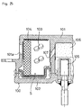
- the present invention relates to a device for inflating an air bag for an automobile and particularly to a gas generator for controlling a deployment process of the air bag.
- a gas generator for rapidly inflating an air bag so as to protect a driver and etc, from an impact caused in a collision of the automobile is incorporated into an air bag module mounted in a steering wheel.
- This gas generator instantaneously generates a large amount of high-temperature gas in response to a collision detection signal of a collision sensor in the event of collision.
- This gas generator includes a housing 100, formed by an upper case 101 and a lower case 102 of a double cylindrical structure of having lids.
- the housing 100 has a structure in which an annular airtight space S is formed in the inside, by abutting and friction-welding at inner cylindrical portions of the upper case 101 and a lower case 102 and outer cylindrical portions thereof.
- gas generating agents 103 and a cylindrical filter member 104 are successively housed from the inner cylindrical portion toward the outer cylindrical portion.
- an igniter 105 ignited in response to a collision detection signal from a collision sensor and an inflammation agent 106 fired by ignition of the igniter 105 are disposed.
- the igniter 105 is ignited in response to the collision detection signal from the collision sensor to fire the inflammation agent 106.
- a flame of the inflammation agent 106 spouts through an igniter hole 107 of the inner cylindrical portion into the airtight space S, and the gas generating agents 103 fires and burns, so that a large amount of high-temperature gas is instantaneously generated.
- the large amount of high-temperature gas flows into the filter member 104, is subjected to slag collection process and cooling process, and flows into an air bag from a plurality of gas discharge ports 101a of the upper case 101 from now on.
- the air bag is rapidly inflated by the large amount of clean gas discharged from the respective gas discharge ports 101a.
- the igniter ignites in response to the collision detection signal from the collision sensor, the large amount of clean gas is instantaneously generated, and then the air bag is rapidly inflated regardless of a form of the collision of the automobile or of a seated posture of the driver. Therefore, in the case the driver is seated near a steering wheel, or even the case the automobile collides at a low speed, the driver receives an impact from the air bag inflating rapidly. As a result, there is a problem that the air bag cannot show a inherent function of protecting the driver.
- a first invention is a gas generator for mainly inflating an air bag for a driver's seat, wherein a gas generating agent is loaded in a combustion chamber in a housing and one or more igniters for firing and burning the gas generating agent in the combustion chamber are mounted in the housing.
- a gas generating agent is loaded in a combustion chamber in a housing and one or more igniters for firing and burning the gas generating agent in the combustion chamber are mounted in the housing.
- one or more of the igniters are disposed eccentrically to an axis of the housing.
- permeability of the high-temperature gas generated in the combustion chamber by combustion of the gas generating agent by the eccentric igniters is lower through a part closest to the respective igniters than through the other part.
- the gas generating agent is fired and burned by the eccentric igniters as described above, combustion is locally generated in the combustion chamber. Therefore, in the first invention, by varying the permeability of the high-temperature gas, it is possible to distribute the gas throughout the combustion chamber and to evenly discharge the clean gas around the housing even if combustion is locally generated in the combustion chamber. As a result, the air bag is uniformly and smoothly inflated. Therefore, in the first invention, the passenger in the driver's seat does not receive an impact caused by uneven deployment of the air bag even if the passenger is seated near the steering wheel. As a result of this, in the first invention, an inherent function of the air bag is performed in safety.
- a second invention is a gas generator for inflating an air bag mainly for a driver's seat, wherein a gas generating agent and a filter member are loaded and disposed in each of a plurality of combustion chambers in a housing and a plurality of igniters for firing and burning the gas generating agents in the respective combustion chambers are disposed in the housing.
- a gas generating agent and a filter member are loaded and disposed in each of a plurality of combustion chambers in a housing and a plurality of igniters for firing and burning the gas generating agents in the respective combustion chambers are disposed in the housing.
- one or more igniters are disposed eccentrically to an axis of the housing.
- permeability of a high-temperature gas generated in the combustion chambers by combustion of the gas generating agents by the eccentric igniters is lower through a part closest to the respective igniters than through the other part.
- the gas generating agents are fired and burned by the eccentric igniters as described above, combustion is locally generated in the respective combustion chambers. Therefore, in the second invention, by varying the permeability of the high-temperature gas, it is possible to distribute the gas throughout the respective combustion chambers and to evenly discharge the clean gas from respective gas discharge ports around the housing even if combustion is locally generated in the respective combustion chambers.
- the second invention by actuating the respective igniters at intervals, it is possible to carry out multistage control of inflation in which the air bag is slowly inflated with a small amount of gas generated in only one combustion chamber in an initial stage of inflation of the air bag and then the air bag is rapidly inflated by adding gas generated in other combustion chambers.
- the passenger in the driver's seat does not receive an impact caused by rapid deployment and inflation of the air bag in the initial stage of inflation and by uneven deployment of the air bag, even if the passenger is seated near the steering wheel.
- an inherent function of the air bag is performed in safety.
- the second invention as a structure for evenly discharge the clean gas around the housing, one or more of structures of the gas passing holes of the inner cylindrical member, the gas discharge ports of the housing, and the filter member are employed. In any of the structures, it is possible to reliably discharge the clean gas from the gas discharge ports around the housing with a simple structure.
- a third invention is a gas generator for mainly inflating an air bag for a driver's seat, wherein a gas generating agent is loaded in a combustion chamber in a housing and one or more igniters for firing and burning the gas generating agent in the combustion chamber are disposed in the housing.
- a gas generating agent is loaded in a combustion chamber in a housing and one or more igniters for firing and burning the gas generating agent in the combustion chamber are disposed in the housing.
- one or more of the igniters are disposed eccentrically to an axis of the housing.
- firing flames of the eccentric igniters are controlled to spout around the axis of the housing.
- the third invention it is possible to start combustion to the gas generating agent in the vicinity of the eccentric igniters and in a large area around the axis of the housing at a distance from the igniters, so that it is possible to instantaneously shift the combustion to overall combustion. Therefore, it is possible to evenly generate the high-temperature gas by the eccentric igniters around the axis of the housing and to evenly discharge the clean gas around the housing.
- the passenger in the driver's seat does not receive an impact caused by uneven deployment of the air bag even if the passenger is seated near the steering wheel, as a result of this the inherent function of the air bag can be performed in safety.
- a fourth invention is a gas generator for mainly inflating an air bag for a driver's seat, wherein gas generating agents and a filter member are loaded and disposed in a plurality of combustion chambers in a housing and a plurality of igniters for firing and burning the gas generating agents in the respective combustion chambers are disposed in the housing.
- gas generator one or more igniters are disposed eccentrically to an axis of the housing. In the gas generator, firing flames of the eccentric igniters are controlled to spout around axis of the housing.
- the fourth invention it is possible to start combustion to the gas generating agent in the vicinity of the eccentric igniters and in a large area around the axis of the housing at a distance from the igniters, so that it is possible to instantaneously shift the combustion to overall combustion. Therefore, it is possible to evenly generate the high-temperature gas by the eccentric igniters around the axis of the housing and to evenly discharge the clean gas around the housing.
- the fourth invention by actuating the respective igniters at intervals, it is possible to carry out multistage control of development in which the air bag is slowly inflated with a small amount of gas generated in only one combustion chamber in an initial stage of development of the air bag and then the air bag is rapidly inflated by adding gas generated in other combustion chambers.
- the fourth invention by actuating the respective igniters at intervals, it is possible to carry out multistage control of inflation in which the air bag is slowly inflated with a small amount of gas generated in only one combustion chamber in an initial stage of inflation of the air bag and then the air bag is rapidly inflated by adding gas generated in other combustion chambers.
- the passenger in the driver's seat does not receive an impact caused by rapid deployment and inflation of the air bag in the initial stage of inflation and by uneven deployment of the air bag, even if the passenger is seated near the steering wheel, as a result of this the inherent function of the air bag can be performed in safety.
- any one of a plurality of firing holes of the igniters, firing holes of firing lids for covering the igniters, and a plurality of firing holes of the igniters opened by the firing flames is employed.
- a fifth invention is a gas generator for mainly inflating an air bag for a driver's seat, wherein a gas generating agent is loaded in a combustion chamber in a housing and one or more igniters for firing and burning the gas generating agent in the combustion chamber are disposed in the housing.
- a gas generating agent is loaded in a combustion chamber in a housing and one or more igniters for firing and burning the gas generating agent in the combustion chamber are disposed in the housing.
- one or more of the igniters are disposed eccentrically to an axis of the housing.
- permeability of a high-temperature gas generated in the combustion chamber by combustion of the gas generating agent by the eccentric igniters is lower through a part closest to the respective igniters than through the other part and firing flames of the eccentric igniters are controlled to spout around the axis of the housing.
- the gas generating agents are fired and burned by the eccentric igniters as described above, combustion is locally generated in the combustion chamber. Therefore, in the fifth invention, by varying the permeability of the high-temperature gas, it is possible to distribute the gas throughout the combustion chamber and to evenly discharge the clean gas around the housing even if combustion is locally generated in the combustion chamber. In the fifth invention, it is possible to start combustion to the gas generating agent in the vicinity of the eccentric igniters and in a large area around the axis of the housing at a distance from the igniters, so that it is possible to instantaneously shift the combustion to overall combustion. Therefore, it is possible to evenly generate the high-temperature gas by the eccentric igniters around the axis of the housing and to evenly discharge the clean gas around the housing.
- the passenger in the driver's seat does not receive an impact caused by uneven deployment of the air bag, even if the passenger is seated near the steering wheel, as a result of this the inherent function of the air bag can be performed in safety.
- a sixth invention is a gas generator for mainly inflating an air bag for a driver's seat, wherein gas generating agents and a filter member are loaded and disposed in a plurality of combustion chambers in a housing and a plurality of igniters for firing and burning the gas generating agents in the respective combustion chambers are disposed in the housing.
- one or more igniters are disposed eccentrically to an axis of the housing.
- permeability of a high-temperature gas generated in the combustion chambers by combustion of the gas generating agents by the eccentric igniters is lower through a part closest to the respective igniters than through the other part and firing flames of the eccentric igniters are controlled to spout around the axis of the housing.
- the gas generating agents are fired and burned by the eccentric igniters as described above, the combustion is locally generated in the respective combustion chambers. Therefore, in the sixth invention, by varying the permeability of the high-temperature gas, it is possible to distribute the gas throughout the respective combustion chambers and to evenly discharge the clean gas from respective gas discharge ports around the housing even if combustion is locally generated in the respective combustion chambers. In the sixth invention, it is possible to start combustion to the gas generating agent in the vicinity of the eccentric igniters and in a large area around the axis of the housing at a distance from the igniters, so that it is possible to instantaneously shift the combustion to overall combustion. Therefore, it is possible to evenly generate the high-temperature gas by the eccentric igniters around the axis of the housing and to evenly discharge the clean gas around the housing.
- the sixth invention it is possible to actuate the respective igniters at short intervals.
- By actuating the respective igniters at intervals it is possible to carry out multistage control of inflation in which the air bag is slowly inflated with a small amount of gas generated in only one combustion chamber in an initial stage of inflation of the air bag and then the air bag is rapidly inflated by adding gas generated in other combustion chambers.
- the passenger in the driver's seat does not receive an impact caused by rapid deployment and inflation of the air bag in the initial stage of inflation and by uneven deployment of the air bag even if the passenger is seated near the steering wheel.
- the inherent function of the air bag can be performed in safety.
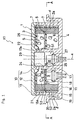
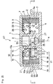
- FIG. 1 is a sectional view of a gas generator used for an air bag for a driver's seat according to the present invention.
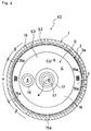
- FIG. 2 is a sectional view taken along a line A-A in FIG. 1.
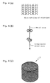
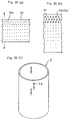
- FIG. 3 is an enlarged perspective view showing a structure of an inner cylindrical member.
- FIGS. 4(a) to 4(c) are drawings showing wire netting of stockinet and crimp-woven metal wire of which a filter member is molded.
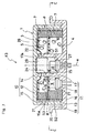
- FIG. 5 is a sectional view showing a gas generator used for the air bag for the driver's seat according to a first modification.
- FIG. 6 is a sectional view taken along a line B-B in FIG. 5.FIG.
- FIG. 7 is a sectional view of a gas generator used for the air bag for the driver's seat according to a second modification.
- FIG. 8 is a sectional view taken along a line C-C in FIG. 7.
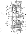
- FIG. 9 is a sectional view of a gas generator used for the air bag for the driver's seat according to a third modification.
- FIG. 10 is a sectional view of a gas generator used for the air bag for the driver's seat according to a fourth modification.
- FIG. 11 is a sectional view taken along a line D-D in FIG. 10.
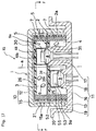
- FIG. 12 is a sectional view of a gas generator used for the air bag for the driver's seat according to a fifth modification.
- FIG. 13 is a sectional view taken along a line E-E in FIG. 12.
- FIG. 14 is an enlarged sectional view of a structure of an eccentric igniter.
- FIG. 15 is an enlarged perspective view of the igniter in FIG. 14.
- FIG. 16 is a sectional view of a gas generator used for the air bag for the driver's seat according to a sixth modification.
- FIG. 17 is a sectional view of a gas generator used for the air bag for the driver's seat according to a seventh modification.
- FIG. 18 is a sectional view taken along a line F-F in FIG. 17.
- FIG. 19 is an enlarged sectional view of a modification of the eccentric igniter.
- FIG. 20 is an enlarged perspective view of the igniter in FIG. 19.
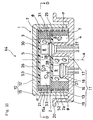
- FIG. 21 is a sectional view of a gas generator used for the air bag for the driver's seat according to an eighth modification.
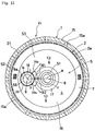
- FIG. 22 is a sectional view taken along a line G-G in FIG. 21.
- FIGS. 23(a) to 23(c) are drawings showing expanded metal of which an inner cylindrical member is molded.
- FIG. 24 is a drawing showing an expanded state of the expanded metal in FIG. 23.
- FIG. 25 is a sectional view of a prior-art gas generator used for the air bag for the driver's seat.
- a gas generator of the invention is mainly used for inflating an air bag for a driver's seat.
- an inside of a housing is partitioned into a plurality of combustion chambers and gas generating agents in each of the combustion chambers are burned by a plurality of igniters, so that a deployment process of the air bag is controllable.
- a clean gas generated by combustion caused by the eccentric igniter is able to evenly discharge from respective gas discharge ports by adopting a structure in which one or more of the respective igniters are disposed eccentrically to an axis of the housing.
- the gas generator used for the air bag for the driver's seat will be described below based on FIGS. 1 to 24.
- the gas generator X1 shown in FIGS. 1 and 2 can control a deployment process of an air bag and can discharge a clean gas evenly around an outer cylindrical portion 15 from respective gas discharge ports 15a by a structure of an inner cylindrical member 2.
- the gas generator X1 includes a housing 1 of short cylindrical shape, the inner cylindrical member 2 mounted in the housing 1, a partition member 5 for partitioning an inside of the inner cylindrical member 2 into upper and lower two combustion chambers 3 and 4, gas generating agents 6 and a filter member 7 loaded and disposed in each of the combustion chambers 3 and 4, and two igniters 8 and 9 for independently burning the gas generating agents 6 in the respective combustion chambers 3 and 4.
- the housing 1 is a double cylindrical structure in which an annular airtight space S is formed inside by using an upper case 10 and a lower case 11.
- the upper case 10 has a disc-shaped upper lid portion 12, an outer cylindrical projecting portion 13 projecting from an outer circumferential edge of the upper lid portion 12, and an inner cylindrical projecting portion 14 projecting from a central portion of the upper lid portion 12 into the airtight space S, and these portions 12, 13, and 14 are integrally molded by an aluminum alloy or the like.
- the lower case 11 has outer cylindrical portion 15 of the short cylindrical shape, a disc-shaped lower lid portion 16 for closing a lower end portion of the outer cylindrical portion 15, and a long inner cylindrical portion 17 extending from a central portion of the lower lid portion 16 into the airtight space S, and these portions 15, 16, and 17 are integrally formed by an aluminum alloy or the like.
- a plurality of gas discharge ports opened into the airtight space S are formed in an upper end portion of the outer cylindrical portion 15.
- the respective gas discharge ports 15a are disposed at predetermined intervals in a circumferential direction of the housing 1 as shown also in FIG. 2.
- the respective gas discharge ports 15a are closed with a burst plate 21 stuck on an inner surface of the outer cylindrical portion 15.
- the burst plate 21 is formed by foil of a metal such as aluminum, for example, and has functions of preventing moisture from entering the housing 1 and adjusting an internal pressure at the time of combustion.
- a plurality of igniter holes 17a opening into the airtight space S are formed in an upper end portion of the long inner cylindrical portion 17.
- the respective igniter holes 17a are disposed at predetermined intervals in the circumferential direction of the housing 1.
- the lower lid portion 16 is integrally formed with a short inner cylindrical portion 18 eccentrically located radially outward from an axis of the housing 1.
- the short inner cylindrical portion 18 projects from between the outer cylindrical portion 15 and the long inner cylindrical portion 17 into inside of the housing 1.
- a projecting length of the short inner cylindrical portion 18 is shorter than the length of the outer cylindrical portion 15, while a projecting length of the long inner cylindrical portion 17 is the same length as the outer cylindrical portion 15.
- a flange cylindrical portion 19 extending along a radial outside of the outer cylindrical portion 15 is formed at an outer circumferential edge of the lower lid portion 16.
- the flange cylindrical portion 19 has a side flange 20 at an upper end portion, and the side flange 20 is bent horizontally to a radially outward direction of the outer cylindrical portion 15.
- the side flange 20 is mounted to a retainer of an air bag module.
- the housing 1 is a double cylindrical structure in which upper and lower end of the outer cylindrical portion 15 and the long inner cylindrical portion 17 are closed with the respective lid portions 12, 16. Specifically, a lower end of the outer cylindrical projecting portion 13 of the upper case 10 is butted against an upper end of the outer cylindrical portion 15 and a lower end of the inner cylindrical projecting portion 14 is butted against an upper end of the long inner cylindrical portion 17 and then the respective lower ends and the upper ends to each other are joined by welding (e.g., friction welding). As a result, the inside of the housing 1 is partitioned into the annular airtight space S and a housing space S1. The annular airtight space S is located between the outer cylindrical projecting portion 13, the outer cylindrical portion 15 and the inner cylindrical projecting portion 14, the long inner cylindrical portion 17, and the housing space S1 is located to inside of the inner cylindrical projecting portion 14 and the long inner cylindrical portion 17.
- the airtight space S in the housing 1 is partitioned into the upper and lower two combustion chambers 3, 4 in an axial direction of the housing 1 by the inner cylindrical member 2 and the partition member 5.
- the inner cylindrical member 2 is formed in a cylindrical shape and is mounted in between the outer cylindrical portion 15 and the short inner cylindrical portion 18, and concentrically located to the inner cylindrical projecting portion 14 and the long inner cylindrical portion 17.
- the inner cylindrical member 2 is extended from the lower lid portion 16 to a vicinity of the upper lid portion 12.
- An upper end of the inner cylindrical member 2 is closed with a lid member 22 press-fitted to an outer periphery of the long inner cylindrical portion 17.
- the inner cylindrical member 2 partitions the airtight space S in the housing 1 into an annular gas passing space S2 between the outer cylindrical portion 15 and the inner cylindrical member 2 and an annular combustion space S3 between the long inner cylindrical portion 17 and the inner cylindrical member 2.
- the inner cylindrical member 2 has a plurality of gas passing holes 2a for connecting the gas passing space S2 and the combustion space S3.
- the respective gas passing holes 2a are disposed axially and circumferentially in the inner cylindrical member 2, as shown also in FIG. 2.
- the number of gas passing holes 2a of a circumferential part area ⁇ in the inner cylindrical member 2 closest to the short inner cylindrical portion 18 is smaller than that in a circumferential part area ⁇ at a distance from the short inner cylindrical portion 18.
- the inner cylindrical member 2 has a structure of which a permeability of gas at the circumferential part area ⁇ closed to the short inner cylindrical portion 18 in the side of the lower combustion chamber 4 is lower than that of the other circumferential part area ⁇ .
- the inner cylindrical member 2 is made of porous sheet steel (e.g., punching metal) formed such that the number of the gas passing holes 2a at the circumferential part area ⁇ in the inner cylindrical member 2 is smaller than that at the other circumferential part area ⁇ , as shown in FIG. 3.
- the inner cylindrical member 2 is formed by molding a cylindrical shape by the porous sheet steel and then joining opposite ends to each other by a joining method such as spot welding.
- the partition member 5 is mounted in between the upper lid portion 12 and the lower lid portion 16, and is mounted in the inner cylindrical member 2, approximately parallel to the upper lid portion 12 and the lower lid portion 16. And partition member 5 partitions the combustion space S3 in inner cylindrical member 2 into the upper and lower two combustion chambers 3, 4 in the axial direction of the housing 1.
- a through hole 24 of a center of the partition member 5 is fitted in an outer periphery of the long inner cylindrical portion 17, and the partition member 5 is positioned at upper side of short inner cylindrical portion 18 and to state of facing the short inner cylindrical portion 18.
- the long inner cylindrical portion 17 is placed to the state of passing through the lower combustion chamber 4 and the partition member 5 and projecting into the upper combustion chamber 3.
- the short inner cylindrical portion 18 is placed to the state of projecting into the lower combustion chamber 4.
- the gas generating agents 6 are loaded into the chambers 3, 4, and the filter member 7 is disposed at surround the gas generating agents 6.
- the filter members 7 of the respective combustion chambers 3, 4 are formed to cylindrical shapes which is freely mounted into the inner cylindrical member 2.
- the filter member 7 of the upper combustion chamber 3 is mounted in the inner cylindrical member 2, and is formed to state of contacting with the lid member 22 from the partition member 5.
- the filter member 7 of the lower combustion chamber 4 is mounted in the inner cylindrical member 2, and is formed to state of contacting with the partition member 5 from the lower lid portion 16.
- Each the filter member 7 is preferably produced at a low cost by press-forming wire netting of stockinet as shown in FIG. 4(a) or an assembly of crimp-woven metal wire as shown in FIG. 4(b) into the cylindrical shape as shown in FIG. 4(c).
- a cushion member 25 in contact with the partition member 5 is disposed in between the gas generating agents 6 and the partition member 5 in the lower combustion chamber 4.
- the cushion member 25 has a function of preventing the gas generating agents 6 from powdering by vibration and a function of a heat insulator for suppressing heat transfer between the combustion chambers 3, 4. Therefore, as the cushion member 25, it is preferable to use elastic material such as ceramic fibers having a function of heat insulation.
- a cushion member 26 in contact with the lid member 22 is disposed in between the gas generating agents 6 and the lid member 22 in the upper combustion chamber 3.
- the cushion member 26 has a function of preventing the gas generating agents 6 from powdering of by vibration.
- elastic material such as silicon rubber and silicon foam as the cushion member 26. It is also possible to use material such as ceramic fibers having the function of heat insulation as the cushion member 26.
- the respective igniters 8, 9 are individually mounted in the housing space S1 and the short inner cylindrical portion 18.
- the respective igniters 8, 9 are joined airtight on a tapered step portions 27 formed in the respective inner cylindrical portions 17, 18 by a sealing members.
- the respective igniters 8, 9 are fixed caulking by bending to inward at a caulked portion 28, a tip end of the respective inner cylindrical portions 17,18.
- the igniter 8 faces to an enhancer 29 in the housing space S1.
- the enhancer 29 is positioned in the upper lid portion 12 side of the upper case 10, and is housed at state of closing the respective igniter holes 17a.
- the respective igniters 8, 9 are ignited based on a collision detection signal from a collision sensor.
- the igniter 8 in the long inner cylindrical portion 17 is positioned on the axis a of the housing 1, and ignites the enhancer 29, and causes the firing flame of the enhancer 29 to spout into the upper combustion chamber 3 through the respective igniter holes 17a.
- the igniter 9 in the short inner cylindrical portion 18 projects into the lower combustion chamber 4 in a position eccentric to the axis a of the housing 1 and is close to the circumferential part ⁇ of the inner cylindrical member 2.
- the enhancer 29 is fired by actuating the igniter 8 only.
- the firing flame of the enhancer 29 spouts in radial directions in the upper combustion chamber 3 from the respective igniter holes 17a throughout the circumferential direction of the housing 1.
- a high-temperature gas is generated.
- transfer of heat of combustion generated in the upper combustion chamber 3 is suppressed (slowed) by the heat insulating function of the cushion member 25 and simultaneous firing of the gas generating agents 6 in the lower combustion chamber 4 is prevented.
- the high-temperature gas generated in the upper combustion chamber 3 flows throughout the circumferential direction of the housing 1 and into the filter member 7, is subjected to slag collection and cooling, and flows through the respective gas passing holes 2a of the inner cylindrical member 2 out into the gas passing space S2.
- the burst plate 21 bursts and a clean gas which is made uniform in the gas passing space S2 is discharged from the respective gas discharge ports 15a into an air bag.
- the air bag starts slow deployment and inflation with a small amount of clean gas generated in only the upper combustion chamber 3.
- the igniter 9 is actuated after a short interval from a start of combustion in the upper combustion chamber 3, the gas generating agents 6 in the lower combustion chamber 4 are forcibly fired, a combustion is started, and a high-temperature gas is generated.
- the combustion in the combustion chamber 4 is started with a state that the gas generating agents 6 around the igniter 9 are burned locally.
- the combustion moves to the circumferential direction of the housing 1, and shifts to overall combustion as the time is passed. Therefore, in an initial stage of combustion in the lower combustion chamber 4, the high-temperature gas generated around the igniter 9 flows into the filter member 7 from a near portion of the igniter 9.
- the clean gas that generated in the lower combustion chamber 4 and that is flowed into the gas passing space S2 is evenly discharged around the outer cylindrical portion 15 from the respective gas discharge ports 15a.
- the air bag shifts to rapid deployment and inflation by a large amount of clean gas discharged from both the combustion chambers 3, 4.
- the air bag starts slow deployment and inflation by the small amount of gas generated in only the upper combustion chamber 3.
- the air bag shifts to rapid-moving deployment and inflation by the large amount of gas that generated in both the combustion chambers 3, 4.
- the airbag is inflated evenly and smoothly with the clean gas that evenly discharged from the respective gas discharge ports 15a around the outer cylindrical portion 15.
- Actuation of the respective igniters 8, 9 is not necessarily required to be carried out at the short interval and actuation of the respective igniters 8, 9 may be properly selected according to a form of the collision of the automobile.
- the respective igniters 8, 9 are actuated simultaneously to rapidly expand and inflate the air bag with the large amount of gas generated in both the combustion chambers 3, 4.
- the respective igniters 8, 9 are actuated at the short interval to slowly expand and inflate the air bag with the small amount of gas in the initial stage of inflation and then to rapidly expand and inflate the air bag with the large amount of gas after the short interval.
- the gas generating agents 6 in the upper combustion chamber 3 are fired forcibly.
- the air bag takes relatively much time to slowly expand and inflate with the small amount of gas.
- the gas generator X1 by actuating the respective igniters 8, 9 at the short interval, it is possible to carry out inflation control such that the air bag is slowly inflated with the small amount of gas generated in only the upper combustion chamber 3 in the initial stage of inflation of the air bag and then is rapidly inflated with the large amount of gas generated in both the combustion chambers 3, 4 (the amount of gas discharged into the air bag can be controlled in two steps).
- the gas generator X1 because the gas discharged from the respective gas discharge ports 15a around the outer cylindrical portion 15 can be made uniform, it is possible to uniformly and smoothly expand and inflate the air bag even if the respective igniters 8, 9 are disposed eccentrically to the axis a of the housing 1 so as to control inflation of the air bag.
- the gas generator X1 has function that the gas is evenly discharged from the respective gas discharge ports 15a around the outer cylindrical portion 15 by adjusting the number of gas passing holes 2a formed in the inner cylindrical member 2, it is also possible to obtain the same function by adjusting opening areas of the respective gas passing holes 2a. If the number or the opening areas of the gas passing holes 2a formed in the circumferential part ⁇ of the inner cylindrical member 2 is (are) increased as a distance from the igniter 9 increases, it is possible to reliably distribute the gas in the combustion initial stage throughout the circumferential direction of the housing 1.
- the deployment process of the air bag can be controlled and the clean gas can be evenly discharged from the respective gas discharge ports 15a around the outer cylindrical portion 15 by structures of the respective gas discharge ports 15a in the outer cylindrical portion 15.
- the same members as those in FIGS. 1 and 2 are provided with the same reference numerals to avoid repetition of description.
- the number of respective gas discharge ports 15a formed in a circumferential part ⁇ of the outer cylindrical portion 15 closest to the igniter 9 in the short inner cylindrical portion 18 is smaller than that in a circumferential part ⁇ of the outer cylindrical portion 15 at a distance from the igniter 9.
- the number of gas discharge ports 15a formed in the circumferential part ⁇ of the outer cylindrical portion 15 is increased as a distance from the igniter 9 increases and the number of gas discharge ports 15a is the largest in the part facing the short inner cylindrical portion 18 through the long inner cylindrical portion 17.
- permeability of gas through the respective gas discharge ports 15a in the outer cylindrical portion 15 is lower in the circumferential part ⁇ close to the igniter 9 in the short inner cylindrical portion 18 than that in the other circumferential part ⁇ .
- the inner cylindrical member 2 uniformly formed with the gas passing holes 2a at predetermined intervals in its axial and circumferential directions is used.
- the collision sensor detects a collision of the automobile and only the igniter 8 is actuated, the high-temperature gas generated in the upper combustion chamber 3 is subjected to slag collection and cooling in the filter member 7 and made uniform in the gas passing space S2 and then starts to be discharged into the air bag similarly to FIG. 1.
- the air bag starts slow deployment and inflation with the small amount of clean gas generated in only the upper combustion chamber 3.
- the high-temperature gas generated around the igniter 9 in the lower combustion chamber 4 passes through the filter member 7 and the inner cylindrical member 2 from the portion close to the igniter 9, is subjected to slag collection and cooling in the filter member 7 and the inner cylindrical member 2, and flows out into the gas passing space S2.
- the clean gas which has flowed out into the gas passing space S2 is once collided with the inner periphery of the outer cylindrical portion 15, a flowing direction of the gas is changed to the axial or circumferential direction of the gas passing space S2, and the gas is flowed toward the respective gas discharge ports 15a in the outer cylindrical portion 15.
- the number of gas discharge ports 15a formed in the circumferential part ⁇ of the outer cylindrical portion 15 is small, the amount of gas discharged from the circumferential part ⁇ into the air bag is restricted and distributed to the circumferential direction of the gas passing space S2. As a result, even if the combustion is locally generated around the igniter 9 in the initial stage of the combustion in the lower combustion chamber 4, it is possible to make the gas discharged from the respective gas discharge ports 15a around the outer cylindrical portion 15 uniform by the number of gas discharge ports 15a formed in the outer cylindrical portion 15.
- the air bag can be inflated according to the form of the collision of the automobile by properly selecting the short interval between actuation of the respective igniters 8, 9. It is also possible that the permeability of the gas through the circumferential part ⁇ is lower than that through the other circumferential part ⁇ by adjusting open areas of the respective gas discharge ports 15a without depending on the number of the formed holes 15a.
- the gas generator X2 because control of inflation of the air bag can be easily carried out and the air bag can be inflated uniformly and smoothly similarly to FIG. 1, the inherent function of the air bag can be performed in safety.
- the deployment process of the air bag can be controlled and the clean gas can be evenly discharged from the respective gas discharge ports 15a around the outer cylindrical portion 15 by a structure of the filter member 7.
- the same members as those in FIGS. 1 and 2 are provided with the same reference numerals to avoid repetition of description.
- the filter member 7 has a structure of which permeability of the gas in the lower combustion chamber 4 is varied in the circumferential direction of the housing 1.
- the filter member 7 has a structure of which the passing of gas through the circumferential part ⁇ closest to the igniter 9 in the short inner cylindrical portion 18 is harder than passing through the circumferential part ⁇ at a distance from the igniter 9.
- the circumferential part ⁇ in the filter member 7 has structures of which the permeability of the gas increases as a distance from the igniter 9 increases, and that the permeability is the highest in the part facing the short inner cylindrical portion 18 through the long inner cylindrical portion 17.
- a rate of voids (hereafter referred to as a void rate) formed by wire netting of stockinet or crimp-woven metal wire (see FIG. 4) is made uniform and the number of layers of the wire netting or the metal wire is increased such that a radial thickness of the circumferential part ⁇ is larger than that of the part ⁇ and that an inside diameter at the circumferential part ⁇ is smaller
- a structure in which the radial thickness of the filter member 7 is made uniform and the wire netting or the metal wire is gathered densely such that the void rate in the circumferential part ⁇ is smaller than that in the part ⁇ , or the like is employed.
- the permeability of the gas through the circumferential part ⁇ close to the igniter 9 in the short inner cylindrical portion 18 on the lower combustion chamber 4 side is lower than that through the other part ⁇ .
- the housing 1 is formed by integrally molding the outer cylindrical portion 15 with the upper lid portion 12 of the upper case 10 concentrically with the inner cylindrical projecting portion 14 and is formed into the structure of double cylindrical portions in which upper and lower end portions of the outer cylindrical portion 15 and the long inner cylindrical portion 17 are closed with the respective lids 12 and 16 by butting an upper end of the outer cylindrical portion 15 of the upper case 10 against an upper end of the outer cylindrical projecting portion 13 of the lower lid portion 17, butting a lower end of the inner cylindrical projecting portion 14 against an upper end of the long inner cylindrical portion 17, and joining the respective lower ends and the upper ends to each other by welding (e.g., friction welding).
- the inner cylindrical member 2 evenly formed with the gas passing holes 2a at predetermined intervals in its axial and circumferential directions is used.
- the collision sensor detects a collision of the automobile and only the igniter 8 is actuated, the high-temperature gas generated in the upper combustion chamber 3 is subjected to slag collection and cooling in the filter member 7 and made uniform in the gas passing space S2 and then starts to be discharged into the air bag similarly to FIG. 1.
- the air bag starts slow deployment and inflation by the small amount of clean gas generated in only upper combustion chamber 3.
- the high-temperature gas generated around the igniter 9 in the lower combustion chamber 4 flows into the filter member 7 from the circumferential part ⁇ close to the igniter 9.
- the filter member 7 has a structure of which the passing of gas through the circumferential part ⁇ is harder than passing through the part ⁇ , a greater part of the high-temperature gas which cannot flow in from the circumferential part ⁇ of the filter member 7 flows in the circumferential direction away from the igniter 9. Then, the high-temperature gas successively flows in from the circumferential part ⁇ of the filter member 7 while flowing away from the igniter 9. A surplus of high-temperature gas which cannot flow in flows in from the circumferential part ⁇ at a greater distance from the igniter 9.
- the air bag can be inflated according to the form of the collision of the automobile by properly selecting the short interval between actuation of the respective igniters 8, 9.
- the gas generator X3 because control of inflation of the air bag can be easily carried out and the air bag can be inflated uniformly and smoothly similarly to FIG. 1, the inherent function of the air bag can be performed in safety.
- the filter member 7 is mounted in the inner cylindrical member 2 to extend from the lower lid portion 16 to the lid member 21 and has a step 7a projecting inward in a radial direction above the igniter 9 on the side of the circumferential part ⁇ of the filter member 7.
- the filter member 7 and the inner cylindrical member 2 partition the airtight space S into the gas passing space S2 and the combustion space S3.
- the combustion space S3 is partitioned into the upper and lower two combustion chambers 3, 4 by the partition member 5 mounted in the filter member 7.
- the partition member 5 is positioned to face the igniter 9 at an upper portion of the igniter 9 in the short inner cylindrical portion 18 by bringing an outer circumferential edge of the partition member 5 into contact with the step 7a of the filter member 7.
- the gas generating agents 6 are loaded.
- the filter member 7 in the respective combustion chambers 3, 4 is integrally molded, it is possible to reduce the number of parts and manufacturing costs as compared with the filter members 7 respectively disposed in the respective combustion chambers 3 and 4. Even if a combustion generated locally around the igniter 9 in the initial stage of the combustion in the lower combustion chamber 4, it is possible to distribute the high-temperature gas in the circumferential direction of the housing 1 by the structure of the filter member 7. Therefore, it is possible to make the gas passing through the gas passing space S2 and discharged from the respective gas discharge ports 15a around the outer cylindrical portion 15 uniform.
- the housing 1 is formed into a structure of a single cylindrical portion and the respective igniters 8, 9 are disposed eccentrically to the axis a of the housing 1.
- the deployment process of the air bag can be controlled and the clean gas can be evenly discharged from the respective gas discharge ports 15a around the outer cylindrical portion 15 by a structure of the filter member 7.
- the same members as those in FIGS. 1 and 2 are provided with the same reference numerals to avoid repetition of description.
- the housing 1 is a single cylindrical structure in which the airtight space S is formed inside by the upper case 10 and the lower case 11.
- the upper case 10 has the outer cylindrical portion 15 and the upper lid portion 12 for closing the upper end portion of the outer cylindrical portion 15, and the outer cylindrical portion 15 and the upper lid portion 12 are integrally molded with an aluminum alloy or the like.
- the lower case 11 has a lower lid portion 16, a outer cylindrical projecting portion 13 projected from the outer circumferential side of the lower lid portion 16, and a flange cylindrical portion 19 extended along an radial outside of the outer cylindrical projecting portion 13 from a periphery of the outer circumferential edge of the lower lid portion 16.
- the lower lid portion 16, the outer cylindrical projecting portion 13, and the flange cylindrical portion 19 are integrally molded with the aluminum alloy or the like.
- the long inner cylindrical portion 17 and the short inner cylindrical portion 18 are integrally molded to the lower lid portion 16 so as to be projected toward the outer cylindrical portion 15, and are disposed eccentrically outward in the radial direction to the axis a of the housing 1.
- the inner cylindrical portions 17 and 18 are symmetrical with the axis a of the housing 1.
- the long inner cylindrical portion 17 is projected to be slightly shorter than the outer cylindrical portion 15.
- the short inner cylindrical portion 18 is projected to be shorter than the long inner cylindrical portion 17.
- the housing 1 is a single cylindrical structure in which the upper and lower end portions of the outer cylindrical portion 15 are closed with the respective lids 12, 16 by butting the lower end of the outer cylindrical portion 15 of the upper case 10 against the upper end of the outer cylindrical projecting portion 13 and joining the lower end and the upper end to each other by welding (e.g., friction welding). As a result, the airtight space S is formed in the housing 1.
- the airtight space S in the housing 1 is partitioned into the annular gas passing space S2 and the combustion chamber S3 by the inner cylindrical member 2 that is located between the respective inner cylindrical portions 17, 18 and the outer cylindrical portion 15.
- the annular gas passing space S2 is located between an outer periphery of the inner cylindrical member 2 and an inner periphery of the outer cylindrical portion 15, and the combustion chamber S3 is located inside the inner cylindrical member 2.
- the inner cylindrical member 2 is extended from the lower lid portion 16 to the vicinity of the upper lid portion 12 and an upper end portion of the inner cylindrical member 2 is closed with a lid member 30.
- the combustion space S3 in the inner cylindrical member 2 is partitioned into the upper and lower two combustion chambers 3, 4 by the partition member 5.
- the partition member 5 is mounted with substantially parallel to the upper lid portion 12 and the lower lid portion 16 in the inner cylindrical member 2 between these lid portions 12 and 16.
- the partition member 5 has a through hole 31 formed eccentrically to a central portion, and is positioned facing the short inner cylindrical portion 18 at an upper side thereof by fitting a through hole 31e on the long inner cylindrical portion 17.
- the long inner cylindrical portion 17 is passing through the lower combustion chamber 4 and the partition member 5 and projecting into the upper combustion chamber 3.
- the short inner cylindrical portion 18 is projecting into the lower combustion chamber 4.
- the gas generating agents 6 are loaded and the filter member 7 is mounted surrounding the gas generating agents 6.
- the filter member 7 has a structure of which permeability of the gas in the lower combustion chamber 4 is varied in the circumferential direction of the housing 1. Specifically, the filter member 7 has a structure of which the passing of gas through the circumferential part ⁇ closest to each inner cylindrical portion 17, 18 is harder than passing through the circumferential part ⁇ at a distance from each inner cylindrical portion 17, 18.
- each filter member 7 is formed so that the permeability of the gas is increased as a distance from each inner cylindrical portion 17, 18 gets longer.
- the filter member 7 is made to inside diameter smaller at the circumferential part ⁇ by a structure member that the number of layers of the wire netting or the metal wire in the circumferential part ⁇ is increased so that a radial thickness of the circumferential part ⁇ is larger than that of the part ⁇ .
- the filter member 7 may be made by a structure material that the wire netting or the metal wire is gathered densely at the circumferential part ⁇ such that the void rate of the circumferential part ⁇ is smaller than that of the part ⁇ .
- the respective igniters 8, 9 are individually mounted and fixed by caulking in the respective inner cylindrical portions 17, 18.
- the igniter 8 in the long inner cylindrical portion 17 is projected into the upper combustion chamber 3 and is located near the circumferential part ⁇ of the filter member 7.
- the igniter 9 in the short inner cylindrical portion 18 is projected into the lower combustion chamber 4 and is in contact with the cushion member 25 and is located near the circumferential part ⁇ of the filter member 7.
- the collision sensor detects a collision of the automobile and only the igniter 8 is actuated, the high-temperature gas generated in the upper combustion chamber 3 is subjected to slag collection and cooling in the filter member 7 and made uniform in the gas passing space S2 and then starts to be discharged into the air bag similarly to FIG. 1.
- the air bag starts slow deployment and inflation with the small amount of clean gas generated in only the upper combustion chamber 3.
- the combustion in the upper combustion chamber 3 starts when the gas generating agents 6 around the igniter 8 are burned locally.
- the combustion moves to the circumferential direction of the housing 1, and shifts to overall combustion as the time is passed. Therefore, the high-temperature gas generated around the igniter 8 in an initial stage of combustion in the upper combustion chamber 3 flows into the filter member 7 from the circumferential part ⁇ located near the igniter 8.
- the passing of gas through the circumferential part ⁇ is harder than the passing of the part ⁇ , a great amount of the high-temperature gas which cannot flow in from the circumferential part ⁇ of the filter member 7 flows in the circumferential direction away from the igniter 8.
- the high-temperature gas successively flows into through the circumferential part ⁇ of the filter member 7 while flowing away from the igniter 8.
- a surplus of the high-temperature gas which cannot flow flows into through the circumferential part ⁇ with a great distance from the igniter 8.
- the high-temperature gas generated around the igniter 9 in the lower combustion chamber 4 is distributed in the circumferential direction of the housing 1 and flows into the filter member 7 by the structure of the filter member 7 similarly to the upper combustion chamber 3.
- the combustion is locally generated around the igniter 9 in the initial stage of the combustion in the lower combustion chamber 4, it can discharge uniformly the gas passed through the gas passing space S2 around the outer cylindrical portion 15 from the respective gas discharge ports 15a.
- the air bag can be inflated according to the form of the collision of the automobile by properly selecting the short interval between actuation of the respective igniters 8, 9.
- the gas generator X4 because control of inflation of the air bag can be easily carried out and the air bag can be inflated uniformly and smoothly similarly to FIG. 1, the inherent function of the air bag can be performed in safety.
- the housing 1 is a single cylindrical structure by using the upper case 10 and lower case 11, and these cases 10, 11 are formed by pressing a stainless steel.
- the upper case 10 is made of forming integrally the upper lid portion 16 and the outer cylindrical portion 15 by pressing the stainless steel.
- the lower case 11 is made of forming integrally the lower lid portion 16 and the flange cylindrical portion 19 by pressing the stainless steel.
- the housing 1 has a structure with excellent property of heat resistance and pressure resistance as compared with the housing molded of the aluminum alloy or the like.
- the respective inner cylindrical portions 17, 18 are provided separately onto the lower lid portion 16 and are projected respectively into the respective combustion chambers 3, 4.
- the housing 1 made of stainless steel as described above has a excellent property of heat resistance and pressure resistance and it is possible to use a non-azide gas generating agent instead of an azide gas generating agent which has been used conventionally.
- the non-azide gas generating agent has a property that is generated easily a high-temperature and high-pressure gas as compared with the azide gas generating agent. Therefore, although the gas generator is required to have the housing 1 with the excellent property of heat resistance and pressure resistance if the non-azide gas generating agent is used, it can use easily the non-azide gas generating agent by employing the housing 1 of the single cylindrical structure made of the stainless sheet steel.
- the deployment process of the air bag can be controlled and the clean gas can be evenly discharged from the respective gas discharge ports 15a by controlling a firing flame of the eccentric igniter 9.
- the gas generator X5 has the housing 1 of the double cylindrical structure similar to that in FIGS. 1 and 2. And the same members as those in FIGS. 1 and 2 are provided with the same reference numerals to avoid repetition of description.
- the eccentric igniter 9 is mounted in the short inner cylindrical portion 18, and its projected portion 9a is projected into the lower combustion chamber 4.
- the projected portion 9a of the igniter 9 has a firing agent fired in response to the collision detection signal (electrical energy) from the collision sensor, and is covered with a cup-shaped firing lid 38 for controlling a spouting direction of the firing flame.
- the firing lid 38 is fitted in the short inner cylindrical portion 18 and has two firing holes 38a for allowing the firing flame of the igniter 9 to spout into the lower combustion chamber 4.
- a flame space S5 is formed between the firing lid 38 and the projected portion 9a.
- the respective firing holes 38a open into the flame space S5 above the projected portion 9a of the igniter 9, and allow the firing flame or the like which collided with a cup bottom 38b of the firing lid 38 to spout into the lower combustion chamber 4 from the flame space S5 (see FIG. 14).
- the respective firing holes 38a are formed in two positions L and M on a side (the axis a side of the housing 1) facing the long inner cylindrical portion 17 on opposite sides of a straight line connecting axes a and b of the respective inner cylindrical portions 17, 18 as a boundary as shown in FIGS. 13 and 15.
- the firing holes 38a in the respective positions L and M open at angles q1 and q2 in opposite directions from the straight line c with respect to the axis b of the short inner cylindrical portion 18 such that the firing flame can spout between the long inner cylindrical portion 17 and the filter member 7 and around the long inner cylindrical portion 17 (the axis a of the housing 1) at a distance from the igniter 9.
- the angles q1 and q2 are preferably equal to each other such that the firing flame of the igniter 9 spouts evenly around the long inner cylindrical portion 17 (the axis a of the housing 1), the angles q1 and q2 are adjustable so as to uniformly burn all the gas generating agents 6.
- the igniter 9 causes its firing flame to intensively spout around the axis a of the housing 1 away from the igniter 9 with the respective firing holes 38a in the firing lid 38 to fire and burn the gas generating agents 6 in the lower combustion chamber 4.
- the inner cylindrical member 2 formed with the gas passing holes 2a at predetermined intervals in axial direction and circumferential direction is used.
- the collision sensor detects a collision of the automobile and only the igniter 8 is actuated, the high-temperature gas generated in the upper combustion chamber 3 is subjected to slag collection and cooling in the filter member 7 and made uniform in the gas passing space S2 and then starts to be discharged into the air bag similarly as FIG. 1.
- the air bag starts slow deployment and inflation with the small amount of clean gas generated in only the upper combustion chamber 3.
- the igniter 9 is actuated after a short interval from a start of combustion in the upper combustion chamber 3, the firing flame of the igniter 9 intensively spouts around the long inner cylindrical portion 17 away from the igniter 9 through the respective firing holes 38a and burns the gas generating agents 6 to thereby generate the high-temperature gas.
- combustion in the combustion chamber 4 starts with the gas generating agents 6 in a large area in the vicinity of the igniter 9 and around the long inner cylindrical portion 17 at a distance from the igniter 9 and then instantaneously moves to the circumferential direction of the housing 1 to shift to overall combustion. Therefore, it is possible to avoid the uneven and local combustion in the vicinity of the igniter 9 and to instantaneously shift the combustion to the overall combustion. As a result, it is possible to generate the high-temperature gas in the combustion chamber 4 evenly around the axis a of the housing 1.
- the high-temperature gas generated in the lower combustion chamber 4 flows throughout the circumferential direction of the housing 1 and into the filter member 7, is subjected to slag collection and cooling in the filter member 7, and uniformly flows into the gas passing space S2 from the respective gas passing holes 2a in the inner cylindrical member 2. Because the clean gas which has flowed into the gas passing space S2 evenly flows into the air bag from the respective gas discharge ports 15a in the outer cylindrical portion 15, the air bag shifts to rapid deployment and inflation with the large amount of clean gas discharged from both the combustion chambers 3, 4.
- the air bag can be inflated according to the form of the collision of the automobile by properly selecting the short interval between actuation of the respective igniters 8 and 9.
- control of inflation of the air bag can be easily carried out similarly as FIG. 1.
- the gas generator X5 by controlling the firing flame of the eccentric igniter 9 to instantaneously shift the combustion to the overall combustion around the axis a of the housing 1, it is possible to make the clean gas discharged from the respective gas discharge ports 15a into the air bag uniform. Therefore, it is possible to uniformly and smoothly expand and inflate the air bag.
- firing lid 38 formed with the two firing holes 38a has been described in the gas generator X5, three or more firing holes 38a may be formed.
- the respective firing holes 38a are disposed such that all the gas generating agents 6 are burned uniformly.
- the gas generator X5 has a structure of which the inside of the inner cylindrical member 2 is partitioned into the upper and lower two combustion chambers 3, 4 with the partition member 5. And the gas generator X5 has a structure of which the gas generating agents 6 and the filter members 7 are disposed in the respective combustion chambers 3, 4.
- FIG. 16 a structure shown in FIG. 16 can be adopted furthermore.
- the combustion space S3 in the filter member 7 obtained by integrally molding the filter member 7 in the respective combustion chambers 3 and 4 and mounting the member 7 in the inner cylindrical member 2 is partitioned into the upper and lower two combustion chambers 3, 4 with the partition member 5.
- the gas generating agents 6 are loaded in the respective combustion chambers 3, 4. If the filter member 7 in the respective combustion chambers 3, 4 is integrally molded, it is possible to reduce the number of parts and manufacturing costs, as compared with the filter members 7 respectively disposed in the respective combustion chambers 3, 4.
- the deployment process of the air bag can be controlled and the clean gas can be evenly discharged from the respective gas discharge ports 15a by controlling firing flames of the respective eccentric igniters 8, 9.
- the gas generator X6 has the housing 1 of the double cylindrical structure similar to that in FIGS. 10 and 11 and the same members as those in FIGS. 10, 11 are provided with the same reference numerals.
- the structure of the igniter 9 similar to that in FIGS. 12 and 13 is employed.
- the eccentric igniter 8 is mounted in the long inner cylindrical portion 17, and its projected portion 8a is projected into the combustion chamber 3.
- the projected portion 8a of the igniter 8 has a firing agent for being fired in response to the collision detection signal (electrical energy) from the collision sensor and is covered with a cup-shaped firing lid 48 for controlling a spouting direction of the firing flame.
- the firing lid 48 is fitted in the long inner cylindrical portion 17.
- a flame space S5 is formed between the firing lid 48 and the projected portion 8a of the igniter 8 similarly as FIG. 14.
- the firing lid 48 has two firing holes 48a for allowing the firing flame of the igniter 8 to spout into the upper combustion chamber 3.
- the respective firing holes 48a open into the flame space 55 above the projected portion 8a of the igniter 8 and allow the firing flame or the like which collides with a cup bottom 48b of the firing lid 48 to spout into the upper combustion chamber 3 from the flame space S5 (see FIG. 14).
- the respective firing holes 48a are formed in two positions N and P on a side facing the axis a of the housing 1 on opposite sides of a straight line e connecting the axis a of the housing 1 and the axis d of the long inner cylindrical portion 17 as a boundary as shown in FIG. 18.
- the firing holes 48a in the respective positions N and P open at angles q3 and q4 in opposite directions from the straight line c with respect to the axis d of the long inner cylindrical portion 17 such that the firing flame can spout between the filter member 7 and around the axis a of the housing 1 at a distance from the igniter 8.
- the angles q3 and q4 are preferably equal to each other such that the firing flame of the igniter 8 spouts evenly around the axis a of the housing 1, the angles q3 and q4 are adjustable so as to uniformly burn all the gas generating agents 6.
- the igniter 8 is located at the position eccentric to the axis a of the housing 1.
- the igniter 8 fires and burns the gas generating agents 6 in the upper combustion chamber 3 by firing flame that intensively spout around the axis a of the housing 1 away from the igniter 8 through the respective firing holes 48a in the firing lid 48.
- the projected portion 9a of the igniter 9 is covered with the firing lid 38 similarly as FIGS. 12 and 13.
- the igniter 9 is located at the position eccentric to the axis a of the housing 1.
- the igniter 9 fires and burns the gas generating agents 6 in the lower combustion chamber 4 by firing flame that spout around the axis a of the housing 1 away from the igniter 9 through the respective firing holes 38a in the firing lid 38.
- the collision sensor detects a collision of the automobile, only the igniter 8 is actuated.
- the firing flame of the igniter 8 is caused to intensively spout around the axis a of the housing 1 away from the igniter 8 through the respective firing holes 48a and the firing flame burns the gas generating agents 6 to thereby generate the high-temperature gas.
- combustion in the combustion chamber 3 starts with the gas generating agents 6 in a large area in the vicinity of the igniter 8 and around the axis a of the housing 1 at a distance from the igniter 8 and then instantaneously moves to the circumferential direction of the housing 1 to shift to overall combustion.
- the high-temperature gas generated in the upper combustion chamber 3 flows throughout the circumferential direction of the housing 1 and into the filter member 7, is subjected to slag collection and cooling in the filter member 7, and flows into the gas passing space S2 from the respective gas passing holes 2a in the inner cylindrical member 2.
- the burst plate 21 bursts and clean gas which has flowed evenly into the gas passing space S2 is discharged from the respective gas discharge ports 15a into the air bag.
- the air bag slowly expands and inflates with a small amount of clean gas generated in the upper combustion chamber 3 only and discharged evenly from the respective gas discharge ports 15a.
- the igniter 9 is actuated after a short interval from a start of combustion in the upper combustion chamber 3, the firing flame of the igniter 9 intensively spouts around the axis a of the housing 1 away from the igniter 9 through the respective firing holes 48a and burns the gas generating agents 6 to thereby generate the high-temperature gas.
- combustion in the combustion chamber 4 instantaneously shifts to overall combustion similarly to the combustion in the upper combustion chamber 3.
- the high-temperature gas generated in the combustion chamber 4 flows throughout the circumferential direction of the housing 1 and into the filter member 7, is subjected to slag collection and cooling in the filter member 7, and uniformly flows into the gas passing space S2. Because the clean gas which has flowed into the gas passing space S2 evenly flows into the air bag from the respective gas discharge ports 15a in the outer cylindrical portion 15, the air bag shifts to rapid deployment and inflation with the large amount of clean gas discharged from both the combustion chambers 3, 4.
- the gas generator X6 because control of inflation of the air bag can be easily carried out and the air bag can be inflated uniformly and smoothly similarly as FIGS. 12 and 13, the inherent function of the air bag can be performed in safety.
- the air bag similarly to the gas generator X1 in FIGS. 1 and 2, the air bag can be inflated according to the form of the collision of the automobile by properly selecting the short interval between actuation of the respective igniters 8, 9.
- FIG. 19 the projected portion 9a (8a) of the eccentric igniter 9 (8) has a cup-shaped firing lid 58 formed with two firing holes 58a and the respective firing holes 58a are closed with a resin seal 59 molded in an inner periphery of the firing lid 58. Inside the resin seal 59, a firing agent for being fired in response to the collision detection signal (electrical energy) from the collision sensor is loaded.
- the collision detection signal electrical energy
- the respective firing holes 58a open in respective positions L, M (N, P) of the igniter 9 (8) at angles q1, q2 (q3, q4) as shown in FIG. 20.
- the firing holes 58a open into the combustion chamber 4 (3) to allow the firing flame to spout around the axis a of the housing 1.
- the number of the firing holes 58a is not limited to two and may be three or more.
- the igniter 9 (8) it is also possible to form the projected portion 9a (8a) of the igniter 9 (8) of a covered body in which the firing agent is loaded and to form a plurality of firing grooves from an inside (or an outside) of the covered body.
- the respective firing grooves are formed in the respective positions L, M (N, P) of the igniter 9 (8) to be thinner than the other part and are opened into the combustion chamber 4 (3) as the firing holes by the firing flame in the igniter 9 (8).
- the firing flame of the igniter 9 (8) can be controlled to spout around the axis a of the housing 1.
- the deployment process of the air bag can be controlled and the clean gas can be evenly discharged from the respective gas discharge ports 15a by the structure of the filter member 7 and by controlling the firing flame of the eccentric igniter 9.
- the gas generator X7 has the housing 1 having the double cylindrical structure and the filter member 7 similar to those in FIGS. 7 and 8 and the same members as those in FIGS. 7 and 8 are provided with the same reference numerals.
- the structure of the igniter 9 similar to that in FIGS. 12 and 13 is employed.
- the filter member 7 in the lower combustion chamber 4 in FIGS. 21 and 22, similarly as FIGS. 7 and 8, has a structure of which the passing of gas through the circumferential part ⁇ closest to the igniter 9 in the short inner cylindrical portion 18 is harder than passing through the circumferential part ⁇ at a distance from the igniter 9.
- the projected portion 9a of the igniter 9 is covered with the firing lid 38 similarly as FIGS. 12 and 13.
- the igniter 9 is disposed in the position eccentric to the axis a of the housing 1 and causes its firing flame to spout around the axis a of the housing 1 away from the igniter 9 through the respective firing holes 38a in the firing lid 38 to fire and burn the gas generating agents 6 in the lower combustion chamber 4.
- the collision sensor detects a collision of the automobile and only the igniter 8 is actuated, the high-temperature gas generated in the upper combustion chamber 3 is subjected to slag collection and cooling in the filter member 7 and made uniformly in the gas passing space S2 and then starts to be discharged into the air bag similarly as FIG. 1.
- the air bag 3 starts slow deployment and inflation with the small amount of clean gas generated in only the upper combustion chamber 3.
- the igniter 9 is actuated after a short interval from a start of combustion in the upper combustion chamber 3, the firing flame of the igniter 9 intensively spouts around the axis a of the housing 1 away from the igniter 9 through the respective firing holes 38a of the igniter 9 and burns the gas generating agents 6 to thereby generate the high-temperature gas. Because combustion in the combustion chamber 4 instantaneously shifts to overall combustion similarly as FIG. 12, it is possible to generate the high-temperature gas in the combustion chamber 4 evenly around the axis a of the housing 1.
- the high-temperature gas generated in the lower combustion chamber 4 flows into the filter member 7 from the circumferential part ⁇ close to the igniter 9.
- the high-temperature gas which has flowed into the filter member 7 is distributed in the circumferential direction of the housing 1 and is evenly discharged around the outer cylindrical portion 15 through the gas passing space S2 from the respective gas discharge ports 15a similarly as FIG. 7.
- the air bag can be inflated according to the form of the collision of the automobile by properly selecting the short interval between actuation of the respective igniters 8, 9.
- control of inflation of the air bag can be easily carried out.
- the gas generator X7 because all the gas generating agents 6 are burned by controlling the firing flame of the igniter 9 and the high-temperature gas is distributed in the circumferential direction of the housing 1 by the structure of the filter member 7, it is possible to reliably and evenly discharge the clean gas from the respective gas discharge ports 15a.
- any structures of the gas passing holes 2a of the inner cylindrical member 2, the gas discharge ports 15a of the housing 1, the filter member 7, and control of the firing flames of the eccentric igniters 8, 9 are employed. By combining these structures, it is possible to evenly discharge the clean gas from the respective gas discharge ports 15a around the outer cylindrical portion 15.
- the upper and lower two combustion chambers 3, 4 are defined by the inner cylindrical member 2 and the partition member 5, it is also possible to dispose the filter member 7 in the respective combustion chambers 3, 4 and to partition the inside of the filter member 7 into the upper and lower combustion chambers 3, 4 with the partition member 5 without mounting the inner cylindrical member 2.
- gas generators X1 to X7 it is also possible to define a plurality of combustion chambers by a plurality of partition members 5 and to dispose the igniter in each the combustion chamber to thereby carry out multistage control of inflation of the air bag.
- gas generators X1 to X7 each having two or more combustion chambers 3, 4 and two or more igniters 8, 9 have been described, the invention is not limited to such gas generators and the following structures can be also employed.
- One of such structures is a structure in which one combustion chamber is formed in the housing, and in which the gas generating agents in the combustion chamber are burned by one igniter, and in which the igniter is disposed eccentrically to the axis of the housing.
- Another structure is a structure in which one combustion chamber is formed in the housing, and in which the gas generating agents in the combustion chamber are burned by the plural igniter, and in which one or more of the igniters are disposed eccentrically to the axis of the housing.
- the invention can be also applied to a gas generator for inflating an air bag for a passenger seat or for a side collision.
- the gas generator for inflating the air bag for the passenger seat or for the side collision includes a long cylindrical housing.
- the inner cylindrical member 2 may be made of expanded metal shown in FIGS. 23(a) to 23(c).
- a plurality of gas passing holes 2a as shown in FIG. 23(b) are formed by uniformly stretching a base metal 63 formed with the large number of slits 63a at predetermined intervals as shown in FIG. 23(a).
- the inner cylindrical member 2 is formed by forming the expanded metal having predetermined length and width into a cylindrical shape and by securing opposite ends to each other by a joining method such as spot welding as shown in FIG. 23(c).
- the base metal 63 is made of a stainless steel sheet that had excellent heat resistance and pressure resistance or made of other sheet steel.
- each slit 63a is formed in such a shape as to be bent toward an inner or outer circumferential side by height h from a plane portion K of the base metal 63 as shown in FIG. 24 in stretch processing in a direction of arrows in FIG. 23(a).
- the plural gas passing hole 2a projecting to the height h at portions of the respective slits 63a in the outer periphery of the inner cylindrical member 2, opening in the circumferential direction, and extending in the axial direction are formed.
- the respective gas passing holes 2a are connected to each other in the circumferential direction.
- the inner cylindrical member 2 made of expanded metal is mounted in the housing 1, even if the inner cylindrical member 2 is expanded and deformed by high-pressure and high-temperature gas caused by combustion of the gas generating agents 6 in the respective combustion chambers 3 and 4, the gas can pass toward the respective gas discharge ports 15a from the plurality of gas passing holes 2a projecting by the height h toward the inner and outer peripheries. Therefore, if the inner cylindrical member 2 is formed of expanded metal, even if the inner cylindrical member 2 is disposed to be in contact with an inner circumferential face of the outer cylindrical portion 15, a successive annular space can be formed on an inner circumferential side of the outer cylindrical portion 15 and can be used as the gas passing space S2.
- the gas generator according to the present invention is suitable for inflating the air bag for the driver's seat.
Landscapes
- Physics & Mathematics (AREA)
- Fluid Mechanics (AREA)
- Engineering & Computer Science (AREA)
- Mechanical Engineering (AREA)
- Air Bags (AREA)
Applications Claiming Priority (5)
| Application Number | Priority Date | Filing Date | Title |
|---|---|---|---|
| JP2876399 | 1999-02-05 | ||
| JP2876399 | 1999-02-05 | ||
| JP3136499 | 1999-02-09 | ||
| JP3136499 | 1999-02-09 | ||
| PCT/JP2000/000613 WO2000046078A1 (fr) | 1999-02-05 | 2000-02-04 | Generateur de gaz |
Publications (3)
| Publication Number | Publication Date |
|---|---|
| EP1155927A1 true EP1155927A1 (de) | 2001-11-21 |
| EP1155927A4 EP1155927A4 (de) | 2004-12-01 |
| EP1155927B1 EP1155927B1 (de) | 2006-03-29 |
Family
ID=26366905
Family Applications (1)
| Application Number | Title | Priority Date | Filing Date |
|---|---|---|---|
| EP00902851A Expired - Lifetime EP1155927B1 (de) | 1999-02-05 | 2000-02-04 | Gasgenerator |
Country Status (6)
| Country | Link |
|---|---|
| US (1) | US6929284B1 (de) |
| EP (1) | EP1155927B1 (de) |
| KR (1) | KR100459589B1 (de) |
| CZ (1) | CZ298910B6 (de) |
| DE (1) | DE60026969T2 (de) |
| WO (1) | WO2000046078A1 (de) |
Cited By (6)
| Publication number | Priority date | Publication date | Assignee | Title |
|---|---|---|---|---|
| EP1090817A1 (de) * | 1999-04-28 | 2001-04-11 | Nippon Kayaku Kabushiki Kaisha | Gasgenerator |
| EP1361971A1 (de) * | 2001-01-26 | 2003-11-19 | Automotive Systems Laboratory Inc. | Doppelkammer-aufblasvorrichtung |
| EP1477375A1 (de) * | 2002-02-22 | 2004-11-17 | Nippon Kayaku Kabushiki Kaisha | Gasgenerator |
| GB2379970B (en) * | 2000-06-12 | 2005-03-16 | Daicel Chem | Multistage type gas generator for air bag |
| US7651128B2 (en) | 2006-04-28 | 2010-01-26 | Daicel Chemical Industries, Ltd. | Inflator |
| WO2012062262A3 (de) * | 2010-10-15 | 2012-07-26 | Trw Airbag Systems Gmbh | Gasgenerator und gassackmodul |
Families Citing this family (24)
| Publication number | Priority date | Publication date | Assignee | Title |
|---|---|---|---|---|
| AU2002212694A1 (en) * | 2000-10-31 | 2002-05-15 | Daicel Chemical Industries Ltd. | Gas generator for air bag and air bag device |
| JP4631189B2 (ja) * | 2001-03-21 | 2011-02-16 | タカタ株式会社 | ガス発生器 |
| KR100621132B1 (ko) * | 2002-02-06 | 2006-09-13 | 니폰 가야꾸 가부시끼가이샤 | 가스 발생기 |
| DE112005000325B4 (de) * | 2004-02-10 | 2013-04-18 | Chuo Hatsujo K.K. | Filterelement und Herstellungsverfahren für dasselbe |
| US7267365B2 (en) * | 2004-03-10 | 2007-09-11 | Automotive Systems Laboratory, Inc. | Inflator |
| US7367584B2 (en) * | 2004-04-19 | 2008-05-06 | Automotive Systems Laboratory, Inc. | Gas generating system |
| US7343862B2 (en) * | 2004-05-27 | 2008-03-18 | Automotive Systems Laboratory, Inc. | Gas generating system |
| US7438315B2 (en) * | 2004-05-28 | 2008-10-21 | Automotive Systems Laboratory, Inc. | Inflator and method of assembly |
| US7814838B2 (en) * | 2004-06-28 | 2010-10-19 | Automotive Systems, Laboratory, Inc. | Gas generating system |
| US7237801B2 (en) * | 2004-08-31 | 2007-07-03 | Automotive Systems Laboratory, Inc. | Gas generating system |
| US7537240B2 (en) * | 2005-02-22 | 2009-05-26 | Automotive Systems Laboratory, Inc. | Gas generating system |
| US7654565B2 (en) * | 2005-06-02 | 2010-02-02 | Automotive Systems Laboratory, Inc. | Gas generating system |
| JP2009500223A (ja) | 2005-06-30 | 2009-01-08 | オートモーティブ システムズ ラボラトリィ、 インク. | ガス生成装置 |
| JP4907931B2 (ja) * | 2005-09-15 | 2012-04-04 | 日本化薬株式会社 | ガス発生器 |
| JP5101923B2 (ja) * | 2007-04-18 | 2012-12-19 | 株式会社ダイセル | 車両の人員拘束用ガス発生器 |
| US7950691B1 (en) | 2007-10-31 | 2011-05-31 | Tk Holdings, Inc. | Inflator body with adapter form end |
| JP5324931B2 (ja) * | 2009-01-15 | 2013-10-23 | 株式会社ダイセル | 車両の人員拘束装置用ガス発生器 |
| CN103124658B (zh) * | 2011-05-12 | 2017-02-22 | 丰田自动车株式会社 | 充气装置及安全气囊装置 |
| JP5912853B2 (ja) * | 2012-05-23 | 2016-04-27 | 株式会社ダイセル | ガス発生器 |
| JP6563825B2 (ja) * | 2015-02-09 | 2019-08-21 | 株式会社ダイセル | ガス発生器 |
| JP6543560B2 (ja) * | 2015-11-26 | 2019-07-10 | 株式会社ダイセル | ガス発生器 |
| CN109641567B (zh) * | 2016-08-29 | 2021-10-08 | 株式会社大赛璐 | 气体发生器 |
| JP6888228B2 (ja) | 2017-07-20 | 2021-06-16 | 株式会社ダイセル | ガス発生器 |
| US11485313B2 (en) * | 2020-06-23 | 2022-11-01 | Autoliv Asp, Inc. | Inflator for a passive vehicle safety device |
Citations (1)
| Publication number | Priority date | Publication date | Assignee | Title |
|---|---|---|---|---|
| EP0844147A1 (de) * | 1996-11-22 | 1998-05-27 | Autoliv ASP, Inc. | Pyrotechnische Aufblaseinrichtung mit reduzierten Filter- Abmessungen und Kartuschen- Aufladungen |
Family Cites Families (18)
| Publication number | Priority date | Publication date | Assignee | Title |
|---|---|---|---|---|
| JPH05286405A (ja) * | 1992-04-15 | 1993-11-02 | Daicel Chem Ind Ltd | エアバッグ用ガス発生器 |
| JP2559669Y2 (ja) * | 1992-09-09 | 1998-01-19 | センサー・テクノロジー株式会社 | ガス発生器 |
| US5711546A (en) * | 1994-03-18 | 1998-01-27 | Oea, Inc. | Hybrid inflator with coaxial chamber |
| US5788275A (en) * | 1994-03-18 | 1998-08-04 | Oea, Inc. | Hybrid inflator |
| US5613705A (en) * | 1995-03-24 | 1997-03-25 | Morton International, Inc. | Airbag inflator having a housing protected from high-temperature reactive generated gases |
| JP3040049U (ja) * | 1996-01-30 | 1997-08-05 | モートン インターナショナル,インコーポレイティド | 適応性のあるエアバッグ膨張装置 |
| US6234521B1 (en) * | 1996-04-08 | 2001-05-22 | Daicel Chemical Industries, Ltd. | Airbag inflator and an airbag apparatus |
| US6283505B1 (en) * | 1996-11-14 | 2001-09-04 | Nippon Kayaku Kabushiki-Kaisha | Gas generator for air bag |
| JP3702074B2 (ja) * | 1997-08-25 | 2005-10-05 | 日本化薬株式会社 | ガス発生器 |
| FR2768501B1 (fr) * | 1997-09-12 | 1999-10-22 | Livbag Snc | Generateur pyrotechnique adaptatif de gaz pour coussin de protection avec dispositif de neutralisation |
| US6189924B1 (en) * | 1997-11-21 | 2001-02-20 | Autoliv Asp, Inc. | Plural stage inflator |
| JPH11222094A (ja) * | 1998-02-06 | 1999-08-17 | Toyota Motor Corp | エアバック用インフレータ |
| US6032979C1 (en) * | 1998-02-18 | 2001-10-16 | Autoliv Asp Inc | Adaptive output inflator |
| JP2000016226A (ja) * | 1998-06-26 | 2000-01-18 | Daicel Chem Ind Ltd | エアバッグ用ガス発生器及びエアバッグ装置 |
| CN1192923C (zh) * | 1998-09-28 | 2005-03-16 | 大赛璐化学工业株式会社 | 用于气囊的气体发生器以及气囊装置 |
| ATE267727T1 (de) * | 1999-02-16 | 2004-06-15 | Daicel Chem | Gasgenerator für einen mehrstufigen airbag und airbagvorrichtung |
| KR100417766B1 (ko) * | 1999-04-28 | 2004-02-05 | 니뽄 가야쿠 가부시키가이샤 | 가스발생기 |
| US6488310B1 (en) * | 2000-03-28 | 2002-12-03 | Daicel Chemical Industries, Ltd. | Hybrid inflator |
-
2000
- 2000-02-04 CZ CZ20012838A patent/CZ298910B6/cs not_active IP Right Cessation
- 2000-02-04 US US09/890,765 patent/US6929284B1/en not_active Expired - Fee Related
- 2000-02-04 DE DE60026969T patent/DE60026969T2/de not_active Expired - Lifetime
- 2000-02-04 KR KR10-2001-7008633A patent/KR100459589B1/ko not_active IP Right Cessation
- 2000-02-04 EP EP00902851A patent/EP1155927B1/de not_active Expired - Lifetime
- 2000-02-04 WO PCT/JP2000/000613 patent/WO2000046078A1/ja active IP Right Grant
Patent Citations (1)
| Publication number | Priority date | Publication date | Assignee | Title |
|---|---|---|---|---|
| EP0844147A1 (de) * | 1996-11-22 | 1998-05-27 | Autoliv ASP, Inc. | Pyrotechnische Aufblaseinrichtung mit reduzierten Filter- Abmessungen und Kartuschen- Aufladungen |
Non-Patent Citations (1)
| Title |
|---|
| See also references of WO0046078A1 * |
Cited By (17)
| Publication number | Priority date | Publication date | Assignee | Title |
|---|---|---|---|---|
| EP1090817A1 (de) * | 1999-04-28 | 2001-04-11 | Nippon Kayaku Kabushiki Kaisha | Gasgenerator |
| EP1090817A4 (de) * | 1999-04-28 | 2005-03-30 | Nippon Kayaku Kk | Gasgenerator |
| US7055855B2 (en) | 2000-06-12 | 2006-06-06 | Diacel Chemical Industries, Ltd. | Gas generator for multi-stage air bag |
| GB2379970B (en) * | 2000-06-12 | 2005-03-16 | Daicel Chem | Multistage type gas generator for air bag |
| EP1361971A1 (de) * | 2001-01-26 | 2003-11-19 | Automotive Systems Laboratory Inc. | Doppelkammer-aufblasvorrichtung |
| EP1361971A4 (de) * | 2001-01-26 | 2005-02-09 | Automotive Systems Lab | Doppelkammer-aufblasvorrichtung |
| US7404573B2 (en) | 2002-02-22 | 2008-07-29 | Nippon Kayaku Kabushiki-Kaisha | Gas generator |
| EP1477375A4 (de) * | 2002-02-22 | 2005-04-06 | Nippon Kayaku Kk | Gasgenerator |
| EP1477375A1 (de) * | 2002-02-22 | 2004-11-17 | Nippon Kayaku Kabushiki Kaisha | Gasgenerator |
| US7651128B2 (en) | 2006-04-28 | 2010-01-26 | Daicel Chemical Industries, Ltd. | Inflator |
| WO2012062262A3 (de) * | 2010-10-15 | 2012-07-26 | Trw Airbag Systems Gmbh | Gasgenerator und gassackmodul |
| US9452729B2 (en) | 2010-10-15 | 2016-09-27 | Trw Airbag Systems Gmbh | Gas generator and airbag module |
| US9511738B2 (en) | 2010-10-15 | 2016-12-06 | Trw Airbag Systems Gmbh | Inflator and airbag module |
| US9643564B2 (en) | 2010-10-15 | 2017-05-09 | Trw Airbag Systems Gmbh | Inflator and airbag module |
| US9815431B2 (en) | 2010-10-15 | 2017-11-14 | Trw Airbag Systems Gmbh | Inflator and airbag module |
| US9840224B2 (en) | 2010-10-15 | 2017-12-12 | Trw Airbag Systems Gmbh | Inflator and airbag module |
| EP3446933A1 (de) * | 2010-10-15 | 2019-02-27 | TRW Airbag Systems GmbH | Gasgenerator und gassackmodul |
Also Published As
| Publication number | Publication date |
|---|---|
| EP1155927A4 (de) | 2004-12-01 |
| CZ298910B6 (cs) | 2008-03-12 |
| US6929284B1 (en) | 2005-08-16 |
| KR100459589B1 (ko) | 2004-12-04 |
| KR20010101424A (ko) | 2001-11-14 |
| WO2000046078A1 (fr) | 2000-08-10 |
| EP1155927B1 (de) | 2006-03-29 |
| DE60026969T2 (de) | 2006-12-21 |
| DE60026969D1 (de) | 2006-05-18 |
| CZ20012838A3 (cs) | 2001-12-12 |
Similar Documents
| Publication | Publication Date | Title |
|---|---|---|
| EP1155927B1 (de) | Gasgenerator | |
| US6659500B2 (en) | Multi-chamber inflator | |
| JP3808100B2 (ja) | 複数の推進剤室を有する可変性非アジド系気体発生器 | |
| JP3781603B2 (ja) | ガス発生器 | |
| JP2732560B2 (ja) | 乗物搭乗者用拘束具の膨張装置 | |
| KR100589993B1 (ko) | 팽창기 | |
| US6485051B1 (en) | Gas generator | |
| US6543805B2 (en) | Dual stage air bag inflator | |
| JP5189083B2 (ja) | モジュール構造および径方向の膨張ガスの流れを有するインフレータ装置 | |
| US5624133A (en) | Prefilter for gas generating air bag inflator | |
| US6701849B2 (en) | Dual stage air bag inflator with secondary propellant cap | |
| EP1056624A1 (de) | Aufblasvorrichtung mit adaptativem gassfluss | |
| JP3285336B2 (ja) | 膨張流体を提供する装置 | |
| US7055855B2 (en) | Gas generator for multi-stage air bag | |
| US6948737B2 (en) | Gas generator for air bag | |
| JPH0818527B2 (ja) | 車輌乗員拘束器の膨張装置 | |
| US7404573B2 (en) | Gas generator | |
| EP1459946A1 (de) | Gaserzeuger für airbag | |
| JPH1191495A (ja) | ガス発生器 | |
| KR100190888B1 (ko) | 차량탑승자 구속기구 팽창장치 및 그 조립방법 | |
| JPH11157412A (ja) | ガス発生器 | |
| WO2001074632A1 (fr) | Generateur de gaz | |
| JP3857892B2 (ja) | 二重チャンバー式インフレータ | |
| JP2004196116A (ja) | ガス発生器 | |
| WO2000044594A1 (fr) | Générateur de gaz |
Legal Events
| Date | Code | Title | Description |
|---|---|---|---|
| PUAI | Public reference made under article 153(3) epc to a published international application that has entered the european phase |
Free format text: ORIGINAL CODE: 0009012 |
|
| 17P | Request for examination filed |
Effective date: 20010830 |
|
| AK | Designated contracting states |
Kind code of ref document: A1 Designated state(s): AT BE CH CY DE DK ES FI FR GB GR IE IT LI LU MC NL PT SE |
|
| RBV | Designated contracting states (corrected) |
Designated state(s): DE FR GB |
|
| A4 | Supplementary search report drawn up and despatched |
Effective date: 20041020 |
|
| 17Q | First examination report despatched |
Effective date: 20050420 |
|
| GRAP | Despatch of communication of intention to grant a patent |
Free format text: ORIGINAL CODE: EPIDOSNIGR1 |
|
| GRAS | Grant fee paid |
Free format text: ORIGINAL CODE: EPIDOSNIGR3 |
|
| GRAA | (expected) grant |
Free format text: ORIGINAL CODE: 0009210 |
|
| AK | Designated contracting states |
Kind code of ref document: B1 Designated state(s): DE FR GB |
|
| REG | Reference to a national code |
Ref country code: GB Ref legal event code: FG4D |
|
| REF | Corresponds to: |
Ref document number: 60026969 Country of ref document: DE Date of ref document: 20060518 Kind code of ref document: P |
|
| ET | Fr: translation filed | ||
| PLBE | No opposition filed within time limit |
Free format text: ORIGINAL CODE: 0009261 |
|
| STAA | Information on the status of an ep patent application or granted ep patent |
Free format text: STATUS: NO OPPOSITION FILED WITHIN TIME LIMIT |
|
| 26N | No opposition filed |
Effective date: 20070102 |
|
| GBPC | Gb: european patent ceased through non-payment of renewal fee |
Effective date: 20070204 |
|
| PG25 | Lapsed in a contracting state [announced via postgrant information from national office to epo] |
Ref country code: GB Free format text: LAPSE BECAUSE OF NON-PAYMENT OF DUE FEES Effective date: 20070204 |
|
| PGFP | Annual fee paid to national office [announced via postgrant information from national office to epo] |
Ref country code: FR Payment date: 20130301 Year of fee payment: 14 Ref country code: DE Payment date: 20130131 Year of fee payment: 14 |
|
| REG | Reference to a national code |
Ref country code: DE Ref legal event code: R119 Ref document number: 60026969 Country of ref document: DE |
|
| REG | Reference to a national code |
Ref country code: FR Ref legal event code: ST Effective date: 20141031 |
|
| REG | Reference to a national code |
Ref country code: DE Ref legal event code: R119 Ref document number: 60026969 Country of ref document: DE Effective date: 20140902 |
|
| PG25 | Lapsed in a contracting state [announced via postgrant information from national office to epo] |
Ref country code: FR Free format text: LAPSE BECAUSE OF NON-PAYMENT OF DUE FEES Effective date: 20140228 Ref country code: DE Free format text: LAPSE BECAUSE OF NON-PAYMENT OF DUE FEES Effective date: 20140902 |